Article

Printing Information Modeling (PIM) for Additive Manufacturing of Concrete Structures

by
Patricia Peralta Abadia
*,
Muhammad E. Ahmad
and
Kay Smarsly
Institute of Digital and Autonomous Construction, Hamburg University of Technology, 21079 Hamburg, Germany
*
Author to whom correspondence should be addressed.
Appl. Sci. 2023, 13(23), 12664; https://doi.org/10.3390/app132312664
Submission received: 20 October 2023 / Revised: 20 November 2023 / Accepted: 23 November 2023 / Published: 25 November 2023
(This article belongs to the Section Civil Engineering)

Abstract

:
In the context of Industry 4.0, construction processes are shifting towards automation by implementing additive manufacturing (AM) of concrete structures, also referred to as concrete printing. Adapting concrete as a printing material entails complex material–process interactions between concrete and manufacturing processes that require specialized data modeling. However, data modeling for the AM of concrete structures has not kept up with concrete printing research and development. Aiming to enhance data modeling for the AM of concrete structures, this paper proposes a semantic modeling approach, referred to as “printing information modeling” (PIM). The PIM approach defines input parameters and material–process interaction in a generic printing information model for designing and planning concrete printing projects. Exchange requirements for concrete printing are identified and evaluated, serving as the basis for the printing information model. The printing information model, as a semantic (or meta) model, is conceptualized using object-oriented modeling concepts, formalized as an ontology, verified as an instantiable semantic model, and validated with a software tool developed as a plug-in for BIM platforms. As a result, a printing information model is developed to serve as a generally valid semantic model for the AM of concrete structures and has the potential to improve data modeling concepts currently deployed for concrete printing.

1. Introduction

Digital manufacturing technologies, such as additive manufacturing (AM), have been at the foreground of efforts to automate and digitalize the architecture, engineering, and construction (AEC) industry in the context of Industry 4.0. AM is defined using the ISO/ASTM standards as a process of producing objects from 3D model data by joining materials layer upon layer [1]. With the application of AM in construction, customization and freeforming may be obtained, and challenges in construction related to performance, productivity, and sustainability may be solved [2]. By deploying printable construction materials, such as concrete, AM methods have been adapted to print large-scale components and structures, resulting in a reduction in construction time, cost, and environmental impact.
The AM of concrete structures, also known as concrete printing, is the most common application of AM in construction. AM methods for concrete printing can be classified into material extrusion, particle-bed binding, and material jetting [3], where extrusion-based and particle-bed-binding-based methods are more mature in terms of technological development. The combination of AM methods and cementitious materials has led to innovative AM systems for fabricating concrete elements and structures without using formwork. Paolini et al. [4] present a review of the application of AM in construction, where AM systems developed for concrete printing are discussed. Established AM systems, such as contour crafting [5] and D-Shape [6], have paved the way for further developments in the AM of concrete structures.
Recent research has focused on developing AM systems [7,8], on advancing printing strategies and optimizing process parameters [9], on material development and characterization [10,11], on optimizing topologies to minimize material waste [12], on numerical modeling and simulations [13], and on including reinforcement to improve ductility [14]. Buswell et al. [15] have reviewed technological issues that affect extrusion-based concrete printing, drawing attention to open research points. To increase the understanding of the underlying physics governing extrusion-based concrete printing, Mechtcherine et al. [16] have given an overview of the material behavior of fresh concrete during the manufacturing process. Furthermore, Perrot et al. [13] have implemented analytical and numerical tools to assess processes in concrete printing as a function of the material properties, the geometry of the components, and the process parameters (e.g., machine settings). However, data modeling for the AM of concrete structures has not kept pace with concrete printing research and development.
Current AM data modeling approaches are based on standardized data exchange considerations described in ISO/ASTM 52950. The digital workflow, described as a dataflow from 3D digital models to physical components, is specified together with the most common data exchange formats, such as the standard tessellation language (STL), the additive manufacturing format (AMF), and the 3D manufacturing format (3MF) [17]. Additional data exchange formats are used for numerical control of AM systems based on G-code (ISO 6983-1) and on the standard for the exchange of product model data compliant numerical control (STEP-NC), which extends ISO 10303 standards in ISO 14649 [18]. The standard data modeling approaches for AM may cause information breaks along the modeling process by decomposing digital computer models into several data formats, resulting in information loss and inconsistencies. Efforts to advance AM data modeling approaches have been carried out by developing AM-related formal descriptions, such as ontologies and semantic models, that encompass the current knowledge in the field (or subfields) of AM. In [18], a data model for AM technologies has been defined to improve the adoption of STEP-NC in AM systems by unifying the dataflow, from design to manufacturing, in a single file. Similarly, ontologies have been developed to support manufacturability analysis [19], interoperability for data management [20], lifecycle data management [21], and data provenance in metal-based AM [22]. Furthermore, efforts to advance and couple data modeling in AM with digitalization approaches in the AEC industry, such as building information modeling (BIM), have started to gain attention. In [23], a framework based on fabrication information modeling is developed to integrate AM planning into BIM workflows, considering material, machine, and process parameters. In [24], a methodology for knowledge-driven decision support systems based on BIM concepts is developed and represented as an application ontology. Integrating lean production principles into the concrete printing process has also been discussed as an approach to address needs regarding bidirectional information flows and databases for design-to-construction workflows in the AM of concrete structures [25].
Current AM data models, however, assume materials that can be controlled by assuring constant process settings (e.g., print speed), well-defined material properties (e.g., grain size), and controlled environmental conditions (e.g., temperature), which differs from the reality of extrusion-based concrete printing [26]. When considering cementitious materials, which present time-dependent rheological behavior, material–process interactions are crucial when defining process settings and toolpaths, as discussed in [15]. Furthermore, the material properties of concrete change over time, having a detrimental effect on the quality of the printed components when material property variations are unaccounted for during manufacturing. Material–process interactions affecting the overall structural properties of printed components are still to be seamlessly integrated into the data modeling approaches used in the digital workflow in the AM of concrete structures to ensure the success of the concrete printing project. Current data modeling approaches limit the AM of concrete structures to a process with a long trial-and-error learning curve to determine the ideal process and material parameters. Therefore, semantic descriptions are necessary to advance data modeling approaches for the AM of concrete structures, formalizing material–process interactions. Also, new data models are required, enabling smoother digital workflows, describing AM input parameters, and allowing the monitoring of material–process interactions in real time.
This study aims at formally describing the digital workflow, the input parameters, as well as interactions between the parameters in concrete printing, following a semantic modeling approach referred to as “printing information modeling” (PIM). The PIM approach represents a step necessary to standardize process information, material information, and geometry information into a unified data model. In this regard, a “printing information model”, i.e., a semantic model, for extrusion-based AM of concrete structures is proposed, building on previous studies from the authors [27,28]. A software tool that deploys building information modeling (BIM) concepts is developed to test the printing information model as a formal basis for BIM-based concrete printing.
This paper is structured as follows. Section 2 gives an overview of the system and process analysis and requirements, integrating the results of a survey conducted in this study among practitioners and researchers. In Section 3, the proposed printing information model is presented, describing parameters and fundamental material–process interactions for AM of concrete structures. The semantic model is validated via a software tool and an example case. In Section 4, the results are discussed in the context of BIM-based concrete printing. The paper concludes with a summary of this study and an outlook on potential future work.

2. System and Process Analysis

An analysis of the concrete printing process is conducted to trace the information along the digital workflow as well as to identify interactions between tasks, actors, and system elements, serving as the basis for the printing information modeling. The analysis is carried out in the context of the AEC industry, using BIM concepts to identify information exchange requirements and preserve semantic information, improving interoperability in the digital workflow. The concrete printing system and process analysis follow the methodology developed for BIM information delivery manuals [29], in which processes are discretized into tasks and the information exchanged between the tasks (i.e., inputs and outputs) is identified as information exchange requirements. In addition, a survey is conducted among concrete printing practitioners and researchers, whose results are integrated into the system and process analysis. The survey aims to address the following research points:
  • Common types of printing systems and software applications currently used for concrete printing;
  • Work areas, actors, and tasks along the digital workflow of concrete printing;
  • Information exchanged among the actors (e.g., inputs and outputs) and material–process interactions observed or relevant for each work area.
The survey is designed as a questionnaire and shared online among 20 practitioners and researchers that have experience and publications in the domains of concrete printing, including design/architecture, civil engineering, mechanical engineering, material science, and robotics. The questions are formulated as a set of multiple-choice and open-ended questions regarding (i) printing systems and software applications employed for concrete printing; (ii) an overview of digital workflows, roles, and areas relevant to the work of practitioners and researchers; and (iii) information required and generated in their work areas. The open-ended questions are intended for practitioners and researchers to elaborate further on the multiple-choice answers. The results of the survey have been collected and processed to complement the system and process analysis with practical knowledge.
From the survey, it is observed that the most common AM method is material extrusion and that robotic systems are favored for conducting research in concrete printing. Three main areas are identified, including AM design and planning, material science, and process control and optimization. The main inputs and outputs regarding slicing, toolpath planning, material design, and process simulation are collected. Material–process interactions are reported, including issues during pumping and extrusion due to variations in the material consistency and issues during the build-up of printed components due to insufficient green strength and setting time.
Overall, the system and process analysis provide insight into the information exchanged along the digital workflow of concrete printing. Hence, the information exchange requirements provide the basis for translating concrete printing parameters and concepts into a general, valid semantic model. In the following subsections, the concrete printing system and the concrete printing process are described and analyzed. Then, the information exchange requirements are identified.

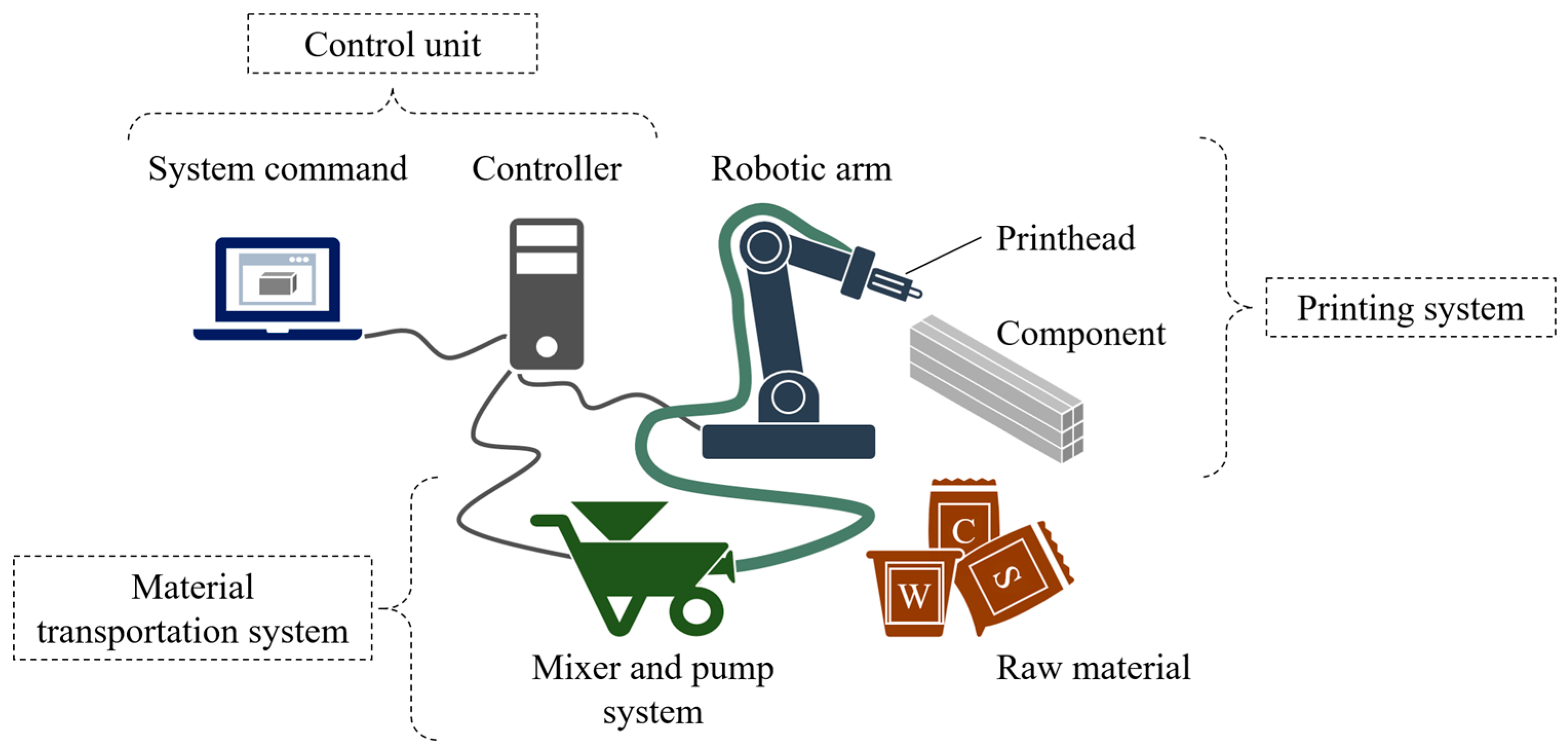
2.1. Concrete Printing System

In extrusion-based concrete printing, concrete is mixed and transported to a printhead, which is attached to a printing system (e.g., gantry and robot). Concrete is extruded through a nozzle located at the tip of the printhead, and it is deposited in place to build a component from a digital 3D model. The elements in concrete printing systems are identified, using a robot concrete printer as an illustrative example. As shown in Figure 1, the robot concrete printer comprises (i) a system command and a controller (control unit), (ii) a robotic arm and a printhead (printing system), and (iii) a mixer and pump system (material transportation system). The components are detailed as follows:
  • Control unit: In the control unit, the system command prepares the data necessary for printing, such as user-defined inputs and generating machine instructions. The system command communicates with the controller via human–machine interfaces. The controller handles the kinematics and electromechanical aspects of the robotic arm and printhead. The controller also processes the machine instructions that define toolpaths and process parameters, controls the multiple axes executing motions of the robotic arm and the printhead, and monitors the performance of the concrete printer using sensing technologies. Depending on the complexity of the printing system, the controller may also handle the material transportation system.
  • Printing system: In the printing system, the robotic arm facilitates the deposition of concrete at desired locations with desired speeds under desired angles. The printhead, as the end effector of the robotic arm, is an element used to extrude concrete, and it consists of an extruding mechanism and a nozzle. The extruding mechanism is a series of parts of the printhead that pushes the concrete through the nozzle. The nozzle, the end part of the printhead, is a hollow element that gives shape to the concrete layer as it is deposited in place to build up a component.
  • Material transportation system: In the material transportation system, the mixer mixes the raw materials to obtain concrete, and the pump transports the concrete from the mixing unit to the printhead, avoiding segregation and bleeding.
The system elements, as shown in Figure 1, have a direct effect on the manufacturing process, the printing material, and the quality of the printed component. Concrete should be extrudable and buildable, where each concrete layer, once in place, is capable of retaining shape and adhering to and carrying the load of subsequent layers. Key rheological properties provide the characteristics necessary for concrete to be printable, defining the evolution of viscosity and yield stress of the material over time. A detailed review of the manufacturing process in extrusion-based concrete printing is presented in [16], including the effects of material parameters (e.g., yield stress) and machine settings (e.g., nozzle height and material flow) in pumping, extrusion, and deposition of concrete layers. In the following subsection, the concrete printing process is described and analyzed.

2.2. Concrete Printing Process

To describe and analyze the concrete printing process, a process map is developed where tasks, actors, and information exchange requirements are identified along the digital workflow for concrete printing. Synergies with the standardized requirements and process chain described in DIN SPEC 17071:2019-12 [30] and with data models developed for metal-based additive manufacturing [22], as well as the results of the survey, are used as the basis for developing the process map. Due to the material–process interactions within concrete printing, material-related tasks are considered part of the concrete printing process.
Following the business process modeling notation [31], the process map is defined as focusing on the design and planning of concrete printing projects, as shown in Figure 2 in terms of an activity diagram. The actors in the activity diagram, defined as designer, engineer, material scientist, and machine operator, develop specific tasks or subprocesses and exchange information, following a sequence that translates digital models into printed components. The concrete printing process starts with design concepts and design specifications to generate geometric models and to specify the printing systems (i.e., machines) required to execute the concrete printing project. On the one hand, machine settings are initially defined and used to design the printing material (i.e., concrete) in an iterative process, which may include material testing, until the design specifications are satisfied and material specifications are derived. On the other hand, with respect to designing the geometry, the geometric models are sliced into layers considering machine specifications (e.g., nozzle sizes). For each layer, toolpaths are planned, and process parameters are assigned to the toolpath profiles according to the process data and the material specifications. Within toolpath planning, simulations are carried out to evaluate the manufacturing process, including the material behavior, to ensure a successful build. As an output of the toolpath planning, AM models are created and, if accepted, used as the basis to generate machine instructions (e.g., CNC code).

2.3. Information Exchange Requirements

The information exchange requirements are described according to information units and attributes, which are collected from the literature—the interested reader is referred to [28]—and from the survey, i.e., from experienced practitioners and researchers in the domains of design/architecture, civil engineering, mechanical engineering, material science, and robotics. Considerations regarding the material–process interactions between concrete and the manufacturing process are included in the information exchange requirements. Furthermore, fabrication information modeling (FIM) concepts introduced in [32] and BIM concepts explored in [33,34] are considered when defining the information exchange requirements for concrete printing. Previous experiences in integrating FIM-based frameworks into BIM, presented in [23], provide insights into the interactions within concrete printing when translating digital models into physical components.
The attributes are analyzed according to completeness (i.e., if an attribute is required or optional) and with respect to interoperability, where completeness ensures the inclusion of all attributes necessary to manufacture components and interoperability ensures a common understanding between tasks and actors. The survey results provide insight into the completeness and interoperability of the attributes. For illustration purposes, the information exchange requirements for AM models are presented in Table 1, where the prerequisites of the information exchange requirements are highlighted in gray. AM models, representing the output of toolpath planning, encompass all information necessary to generate machine instructions, including process data and material specifications. Toolpaths are usually described by sets of points defining printing and axis paths. Material–process interactions are represented using toolpath profiles, which are evaluated via material modeling and manufacturing process simulations. Further information on the information exchange requirements for concrete printing may be found in a previous study by the authors presented in [28].
Based on the information exchange requirements, the classes as well as the interactions between the classes necessary for AM data modeling are identified. In the following section, the printing information model for additive manufacturing of concrete structures is presented.

3. Printing Information Model for Additive Manufacturing of Concrete Structures

In this section, the printing information model is developed, aiming to formalize the information necessary for designing and planning concrete printing projects through a single semantic model based on object-oriented modeling concepts, materialized in the form of a semantic model and an ontology. Since the terminology with respect to “semantic models” and “models” differs depending on the field of research, it must be noted that in this study, a “semantic model” is considered a metamodel to be instantiated into specific “models”, in compliance with [35]. In other words, the models, representing extracts of the real world, are instances of the metamodel, which formally defines the structure, semantics, and constraints of the models. Metamodels are used as schemas to develop software applications as well as databases and may be extended to support future needs of the extracts of the real world.
The model developed for printing information modeling, hereinafter referred to as the PIM model, focuses on extrusion-based AM of concrete structures and describes the semantics of material–process interactions. The printing information model is developed in four steps: (i) conceptual modeling, (ii) formal modeling, (iii) verification, and (iv) validation.
In the first step, aspects and interactions within concrete printing are conceptualized in the form of a knowledge map and structured as a semantic model. The knowledge map aids in categorizing input parameters in AM data modeling into process-related, material-related, and geometry-related information. Then, the information exchange requirements defined in Section 2, encompassing the input parameters and interactions within concrete printing, are mapped into the semantic model in terms of classes and interactions between the classes. The semantic model is described using the Unified Modeling Language (UML) because of its comprehensibility to engineers and rich semantics [36]. In the second step, the semantic model is translated into an ontology that allows knowledge-based reasoning to be used for refining the semantic model. In the third step, the PIM model is verified for correctness by performing logic inference and SPARQL queries on the ontology. SPARQL is the standard protocol and resource description framework (RDF) query language and is used to query information from data sources that can be described based on the RDF standard [37]. In the fourth step, the PIM model is validated through a software tool using an example case. In the following subsections, the steps to develop the PIM model are presented.

3.1. Conceptual Modeling of the Printing Information Model

To conceptualize the information necessary for designing and planning concrete printing projects, aspects and interactions within concrete printing are summarized in the knowledge map and then structured in the semantic model. The knowledge map, shown in Figure 3, abstracts printed components according to process-related, material-related, and geometry-related aspects. Printed components are designed and planned within the context of a building or construction project, with design specifications that consider specific AM methods and printing systems. Printed components, represented by the Component entity, can be described as outputs of manufacturing processes (Process entity), are composed of materials (Material entity), are characterized by specific geometries (Geometry entity), and are situated within specific environments (Environment entity). The manufacturing processes receive printable materials and digital models of the geometry of the components as inputs and are executed according to process parameters. The manufacturing process, to ensure manufacturability, may modify the geometry features of the components and the material properties due to the effects of the underlying physics of the manufacturing process. Material properties may constrain process parameters, e.g., viscosity limiting the material flow rate, and may modify geometry features, such as overhang angles and deposition deformation. The structural properties of the printed components are related to the material properties and the geometry features of the components. For example, the stiffness of printed components is related to the elastic modulus of the material and the inertia of the components. Furthermore, environmental conditions may modify material properties, e.g., yield strength during curing, as well as structural properties, such as durability.
Based on the information exchange requirements, interactions between process-related and material-related aspects are identified within the knowledge map and further explored. It should be noted that, when identifying interactions within concrete printing, a general assumption is made that the AM methods and printing systems are selected before defining the geometry features and materials of the components. Material–process interactions include process parameters that are constrained by material parameters and material parameters that are modified via the manufacturing processes. Following the insight into material–process interactions presented in [9,15,16], on the one hand, the rheological behavior of concrete constrains process parameters during pumping and extrusion. On the other hand, process parameters can modify material properties, for example, by incorporating admixtures or local vibration during extrusion and deposition. Material–process interactions are usually evaluated by modeling the material and simulating the manufacturing process during design and planning of concrete printing projects, as has been shown in [13].
Building upon the knowledge map as an outcome of the system and process analysis, which aids in categorizing the input parameters and interactions in AM data modeling, the UML representation of the PIM model is developed. As mentioned above, the main parameters involved in concrete printing are coherently categorized into classes, and the interactions between the classes are described with semantic relationships. Moreover, the PIM model is refined in an iterative process based on knowledge-based reasoning. As a result, the PIM model is an understandable and instantiable metamodel that can be instantiated for BIM-based concrete printing in compliance with the Industry Foundation Classes (IFC) standard.
When designing the PIM model, three simplifications are assumed to ensure software and hardware independence. First, the geometry information is assumed to be describable using concepts of standardized data models for geometry representations, such as the IFC standard. Standardized geometry representations support geometric descriptions independently from software tools, ensuring interoperability. Second, nesting features in the PIM model can aid in the description of support structures necessary for overhangs, assuming that the same process method and printing system are employed for the components and the support structures. Support structures are dependent on the type of process method and printing system, and their implementation may be described as a subprocess within the printing process, where support structures are either placed on site (e.g., support formwork) or selectively printed using a sacrificial material (e.g., plaster). By nesting the support structure implementation, the printing process may be described as a continuous process, avoiding issues related to hardware. Third, similar to the support structures, aggregation features in the PIM model can aid in the description of reinforcement solutions by aggregating components. Reinforcement solutions may be implemented in parallel with the printing process, taking place before, during, or after printing, depending on the type of process method and printing system. By aggregating the reinforcement and the components, it is possible to describe the reinforcement solutions independently from the hardware.
Figure 4 presents an extract of the PIM model in the form of a UML class diagram depicting the structure of a printed component, i.e., classes and semantic relationships. On the one hand, as can be seen from Figure 4, printed components (AMComponent class) are defined as part of buildings (Building class), providing context to concrete printing projects. On the other hand, printed components are described as outputs of AM processes (AMProcess class), have constituent materials (Material class), and have geometry representations (Geometry class). The AMProcess class includes process-related information necessary for slicing, toolpath planning, and machine control in extrusion-based concrete printing. The Material class refers to material-related information necessary for concrete printing that is generalized for materials, such as concrete (the main material) and plaster (the support material). The Geometry class describes geometry-related information that may be inherited from 3D digital models and that may be generated during planning. A more detailed UML class diagram for the PIM model is presented in Appendix A. For the sake of clarity, details such as multiplicities, attributes, and operations are omitted in Figure 4.
The AMProcess class has a composition relationship with the classes MachineData, SlicingData, ToolpathData, ControlData, MonitoringData, and ProcessBoundaryCondition. The MachineData class encompasses data from the machines used in the printing system, including system data (SystemData class) reflecting the actual status of the machines, machine settings parameters (MachineSetting class) defined by operators, and machine specifications (MachineSpecification class) describing the machines characteristics. The SlicingData class includes the slicing parameters and uses the machine specifications and feature parameters (Feature class) as inputs to generate contour lines (ContourLine class). The ToolpathData class collects parameters used to determine toolpaths and printing strategies using the data from the SlicingData class, from the ContourLine class, and from material properties that impact the manufacturing process (TemporalBehaviour class). The ControlData class refers to data that allows machine control by modifying the MachineSetting class. The MonitoringData class collects data from sensor nodes implemented in the machines that allow monitoring of the SystemData class. ProcessBoundaryCondition refer to boundary conditions that dominate the manufacturing process, including results from simulation models such as process constraints and machine constraints. The process boundary conditions may be used to modify the ToolpathData class and may affect the properties of the material in a hardened state (HardenedStateProperty class).
The Material class has a composition relationship with the classes MaterialSpecification, MaterialComposition, MaterialProperty, MaterialTest, and MaterialBoundaryCondition. The MaterialSpecification class encompasses data resulting from the design of the material. From the material specifications, material compositions (the MaterialComposition class) are defined. In the case of concrete, the material composition refers to the mix design, where changes in the mix design modify the material properties (MaterialProperty class) of concrete, including hardened state, fresh state, and temporal behavior. Material tests, denoted by the MaterialTest class, are used to identify material properties and material boundary conditions (MaterialBoundaryCondition class), which include environment constraints and material constraints.
The Geometry class has a composition relationship with the classes Dimension, FeatureParameter, CoordinateSystem, ContourLine, and GeometryBoundaryCondition. The Dimension class provides dimensional consistency between 3D digital models (i.e., geometric features) and printing systems in terms of dimensions, units, and scaling. Geometric feature parameters are described with the FeatureParameter class, including the classes Location, Orientation, Shape, and CrossSection. The locations and orientations of geometric features are described relative to a coordinate system (CoordinateSystem class), allowing the connection of geometric features to compose the geometry of a component. Curves defined by geometric features are represented with the ContourLine class, which stores the curves or polylines generated from slicing and is used as input for toolpath planning to describe profiles for each layer. The geometry boundary conditions (GeometryBoundaryCondition class), including feature constraints and tolerance constraints, are dependent on the material boundary conditions and on the machine constraints, which affect the manufacturability of geometric features.
Material–process interactions are described in the UML class diagram as semantic relationships, as highlighted in blue in Figure 4. While planning concrete printing projects, material properties must be used as inputs for toolpath planning, in particular those pertinent to the rheological behavior of concrete that changes over time. Profiles of the material properties may be generated during simulations that allow for the evaluation of the success of the build. Process boundary conditions depend on the material boundary conditions, which impact both process constraints and machine constraints. In particular, process constraints may modify the hardened properties of the materials due to the material anisotropy resulting from the layered build-up and the effect of loads acting upon the layers. For example, dry environments may have detrimental effects on the material properties, diminishing the yield strength developed during curing and constraining the range of optimum process parameters, such as maximum build height. To provide knowledge-based reasoning, the PIM model is formalized into the ontology in the following subsection.

3.2. Formal Modeling of the Printing Information

Unified Modeling Language, allowing for the visualization of semantics in great detail and being easily comprehensible for engineers, supports the development of software tools and information systems necessary for designing and planning concrete printing projects. However, UML is bound to closed-world assumptions and may contain design errors leading to unsatisfiable concepts [38]. To enable open-world assumptions for knowledge-based reasoning, to provide vocabulary, and to verify the PIM model’s satisfiability, a printing information ontology that formalizes the previous UML class diagram for the Web Ontology Language (OWL) is developed. Based on the ontology, the PIM model is refined in an iterative process. The ISO-standardized Basic Formal Ontology (BFO) is used as an upper-level ontology as it provides support for information exchange [39]. Classes referring to objects and materials are aligned with the top-level entity BFO:Material_entity, classes referring to geometry representations and sites are aligned with the top-level entity BFO:Immaterial_entity, classes referring to quality information are aligned with the BFO:Quality entity, and classes referring to processes are aligned with the BFO:Occurrent entity. Attributes of the classes are defined as data properties, while multiplicity conditions are described with cardinality axioms. Furthermore, the semantic relationships between the classes are described using class properties, axioms, and description logic (DL) rules. Figure 5 shows an extract of the alignment of the classes with the BFO hierarchy for the printing information ontology, hereinafter referred to as PIM-O.
The PIM-O is built following a bottom-up construction strategy, allowing alignment with other domain ontologies, such as ifcOWL [40]. For example, concepts in ifcOWL have been enhanced using BFO as a basis to improve interoperability [41]. Figure 6 and Figure 7 present extracts of the PIM-O to illustrate the class hierarchy and semantic relationships. An overview of axioms in PIM-O is provided in Appendix B. The class hierarchy has been defined in compliance with the BFO upper-level ontology and the ifcOWL domain ontology with eight top-level classes: Geometry, Function, Material, Object, Process, Quality, Role, and Site. The ontology can be represented in four views: (i) component view, (ii) process view, (iii) material view, and (iii) geometry view.
In the component view (Figure 6a), all views are linked and contextualized within concrete printing projects, where an AMComponent, representing building elements (e.g., walls, columns, beams, and support structures), is part of a Building and has qualities such as structural properties (Structural_property) and load patterns (Load_pattern). Furthermore, a Component is an output of an AMProcess, which has materials (Material) as a resource and takes digital models (Geometry) as inputs. As can be noted, the ontology further formalizes the semantic relationships described in the UML-based printing information model. In a similar manner, the process, material, and geometry views are defined, where relevant semantic relationships are described below.
In the process view (Figure 6b), AM processes are described according to the definitions and concepts stated in the international standards [1,17,30], focusing on extrusion-based AM methods. An AM_process, comprising tasks (AM_task), is characterized by building components in a layer-by-layer manner, using resources such as machines (Machine) and materials (Material). AM processes have actors (Actor) involved in the tasks with roles and functions, as defined in Section 2. Furthermore, process qualities include machine data, slicing data, toolpath data, control data, monitoring data, and process boundary conditions. Process boundary conditions encompass process and machine constraints, which modify material qualities as well as other process qualities.
In the material view, materials in the AM process, such as concrete and plaster, are described (Figure 7a). Material in an AMProcess has a role (MaterialRole) and fulfills a function. Material-related qualities include material specifications, material composition, material properties, material tests, and material boundary conditions. Constraints that modify material properties, such as environment and material constraints, are defined as material boundary conditions. Furthermore, material constraints (e.g., material distribution) and environment constraints (e.g., thermal performance) depend on geometry-related information described in the geometry view. The geometry view (Figure 7b) describes geometry representations of components, including features (Feature) and parts (Part). Geometry-related qualities encompass dimensions, feature parameters, coordinate systems, contour lines, and geometry boundary conditions. Feature parameters are modified by geometry boundary conditions, which include feature and tolerance constraints.
In addition to class definitions, interactions specified in the PIM model are included in the PIM-O as semantic relationships, using description logic rules that link qualities defined in the process, material, and geometry views. For example, the semantic relationships between the AMComponent class, the SupportMaterial class, and the ReinforcementMaterial class (subclasses of MaterialRole) are described in Listing 1. Further DL rules are presented in Appendix C. In the following subsection, the consistency of the semantic relationships defined in the PIM model is verified.
Listing 1. Description logic rules for the AMComponent class.
AMComponent ( x )     hasMaterial ( x ,   y )     Material ( y )     hasRole ( y ,   z )     SupportMaterial ( z )
   AMComponentSupport ( x )
AMComponent ( x )     hasMaterial ( x ,   y )     Material ( y )     hasRole ( y ,   z )     ReinforcementMaterial ( z )
   AMComponentReinforcement ( x )

3.3. Verification of the Printing Information

The PIM model is verified for correctness using the PIM-O through model checking and conducting competency questions. On the one hand, model checking aims to identify errors in the design of the ontology, such as classes that cannot be instantiated. On the other hand, competency questions are a set of questions that determine the scope or intention of an ontology and must be able to be answered correctly based on the ontology. Therefore, the PIM-O is checked on a terminological level (through model checking), which delineates classes and relationships, and on an assertional level (through the competency questions), which relates instances to classes. Furthermore, it should be noted that model checking is carried out using logic inference using a reasoner, while the competency questions are queried using SPARQL queries. In the following paragraphs, an overview of the verification is presented.

3.3.1. Model Checking

The model-checking tests conducted in this study comprise (i) ontology consistency checking, (ii) concept satisfiability checking, and (iii) concept subsumption checking, as illustrated in Table 2, using the Pallet reasoner [42]. The Pallet reasoner is a tool used to check whether an ontology O satisfies an axiom α (formally written as O α ). The results of the model-checking tests are shown in Table 2. As can be observed, the PIM-O positively satisfies the model check tests on the terminological level.

3.3.2. Competency Questions

Applying competency questions is a well-established method for ontology checking [43]. Accordingly, competency questions are developed based on the information exchange requirements to check the PIM-O at the assertional level. SPARQL queries are used to answer the competency questions based on the structure and axioms defined in the PIM-O. The queries consist of two parts: a “select” clause identifying variables and a “where” clause providing conditions to be matched according to triple patterns (i.e., subject–predicate–object statements), as shown in the listings below. For illustration purposes, querying a competency question (CQ) is shown with the examples of competency questions CQ1 and CQ2.
The competency question “CQ1: What kind of components can be 3D-printed?” addresses the types of components that are outputs of AM methods. CQ1 is answered by querying the class hierarchy directly, as shown in Listing 2. The results obtained in the query Q1 show that subclasses of the class AMComponent exist for walls, beams, columns, support structures, and reinforcement structures.
Listing 2. Example SPARQL query Q1 for competency question CQ1.
SELECT ?componentType
WHERE {
     ?componentType rdfs:subClassOf pimo:AMComponent
     }
The competency question “CQ2: Identify walls that are designed using concrete as main material” addresses the relationship between components and materials. Instances of the AMComponentWall class (e.g., wall_1OG and wall_2OG) are queried to answer CQ2, as shown in Listing 3. The results obtained in the query Q2 show that it is possible to identify component instances according to the role of the materials.
Listing 3. Example SPARQL query Q2 for competency question CQ2.
SELECT ?componentType
WHERE {
     ?wall rdf:type pimo:AMWallComponent.
     ?wall pimo:hasMaterial ?material .
     ?material rdf:type pimo:Concrete .
     ?material pimo:hasRole ?role .
     ?role rdf:type pimo:Main_Material .
     }
Further competency questions are applied to evaluate process-related, material-related, and geometry-related information of components based on instances of the AMProcess class (e.g., cp_Process1), the AMComponentWall class (e.g., wall_1OG and wall_2OG), and the Concrete class (e.g., concrete_M1B1). The instance cp_Process1 has concrete_M1B1 as a material resource, presenting a green strength of 3.6 kPa (property_GreenStength) at an age of 15 min identified with a shear vane test (test_VaneTest01). The instance wall_1OG is an output of cp_Process1 and presents a bulk density of 2070 kg/m3 (property_BulkDensity). The queries representing competency questions 3, 4, and 5 are listed below, as shown in Listings 4–6. Table 3 summarizes the results of the illustrative competency question queries. In summary, the results show that the PIM-O correctly answers the competency questions on the assertional level.
Listing 4. Example SPARQL query Q3 for competency question CQ3.
SELECT ?process
WHERE {
     ?wall pimo:isOutput ?process .
     ?process rdf:type pimo:AMProcess .
     ?wall rdf:type pimo:AMComponentWall
     }
Listing 5. Example SPARQL query Q4 for competency question CQ4.
SELECT ?wall
WHERE {
     ?wall pimo:hasProperty ?property .
     ?wall rdf:type pimo:AMWallComponent .
     ?property rdf:type pimo:Density .
     ?property pimo:hasValue ?denistyValue .
     FILTER (?denistyValue >= 2050
          && ?denistyValue <= 2080)
     }
Listing 6. Example SPARQL query Q5 for competency question CQ5.
SELECT ?freshStateProperty ?materialTestData
WHERE {
     ?freshStateProperty pimo:isIdentifiedBy ?materialTestData
     }
Based on the positive results of the competency questions on the PIM-O, the correctness of the PIM model is verified. Hence, the PIM model, representing a metamodel, can be instantiated into specific models that are used for designing and planning concrete printing jobs. In the following subsection, the PIM model is validated.

3.4. Validation of the Printing Information Model

The validation aims to test if the PIM model is suitable to describe process, geometry, and material input parameters as well as interactions between the parameters in AM data modeling of concrete structures. The validation is conducted by implementing the PIM model into a software tool to collect, generate, and store the parameters necessary for AM of concrete structures. The UML diagram guides the development of the software tool, while the PIM-O provides the knowledge necessary for data integration and data storage. Building upon previous work of the authors [27], the software tool has been developed using the PIM model as the backbone, and it integrates BIM concepts into the concrete printing processes. As an illustrative example, a cylindric tank is planned for concrete printing using the software tool to generate toolpaths and gather inputs for simulating the build-up process.
The software tool is written as a plug-in for BIM platforms for designing and planning concrete printing projects, and it generates specific models (i.e., instances) from the PIM model. The software tool, referred to as the “PIM tool”, incorporates algorithms for (i) slicing, (ii) toolpath planning, and (iii) CNC code generation. The inputs of the PIM tool are user-defined parameters for process-related information (e.g., machine data, slicing data, and toolpath data) and material-related information (e.g., material specifications and material properties), which extend the BIM models. The PIM tool updates the BIM models as the slicing and toolpath planning are executed and outputs CNC code as machine instructions for concrete printers.
For the exemplary case, the software tool facilitates the generation of information necessary for simulating the build-up process of the cylindric tank, in particular the temporal behavior of early-age concrete in accordance with the user-defined process parameters (printing speed and layer interval time), as shown in Figure 8. The information is tabulated and stored as a file, facilitating its interoperability with finite element analysis (FEA) software tools. The information is fed to a finite element model, and the build-up process is simulated. The results of the simulation are compared with those reported in the literature to evaluate the completeness of the inputs.
The cylindrical tank is prepared for simulating the concrete printing process based on a BIM model, as shown in Figure 9. The cylindrical tank is designed with an inner radius of 250 mm, a thickness of 60 mm, and a height of 600 mm. The printing system is a robot concrete printer with a printing area of 2500 mm × 3000 mm × 4000 mm (L × W × H), a nozzle size of 25.4 mm, and a printing speed range between 3000 mm/min and 48,000 mm/min. Based on the nozzle size of the printing system, a layer height of 15 mm and an extrusion width of 30 mm are defined as slicing parameters. Toolpath parameters include a spiral layer-by-layer strategy with a boundary thickness of two adjacent filaments. A printing speed of 5000 mm/min is chosen as a machine setting with a layer interval time of 0.31 min. The material-related information is described based on the material model presented in [44]. Early-age concrete is modeled as a cohesive material with a Mohr-Coulomb failure criterion. The temporal behavior of early-age concrete regarding yield stress (i.e., green strength) is modeled using time-dependent parameters, such as cohesion and Young’s modulus, as well as constant parameters, such as internal friction angle, Poisson’s ratio, and dilatancy angle. The concrete printing process is simulated by gradually adding layers and updating the yield stress over time. Border conditions include free radial deformation, a fixed support at the bottom layer, and self-weight loading conditions. The input parameters are fed into the finite element model for further analysis. The finite element model is used to perform a deformation analysis to determine the maximum build height that can be achieved with the defined printing strategy and machine settings.
The validation example case demonstrates that the PIM model is suitable for designing and planning concrete printing projects using BIM models, representing components to be printed as inputs. With the PIM tool, information from BIM models can be processed, enabling model updates. User-defined parameters are used as a basis to execute algorithms and generate the information necessary for simulating the build-up process. Hence, BIM models are extended to include material-related information, such as temporal behavior, and process-related information, such as profiles for each layer. The PIM model has therefore been shown to be suitable to describe parameters and material–process interactions in concrete printing for simple components.
Even though the PIM tool can be coupled with BIM platforms, limitations regarding complex structures and data transferability are observed during validation. On the one hand, the algorithms in the PIM tool perform satisfactorily for structures with simple geometries, but errors in toolpath planning may occur for structures with complex geometries. On the other hand, data cannot be transferred directly to FEA software tools, so a work-around is presented in this study by storing the data as files. In the following section, the results of this study are discussed.

4. Discussion of the Results

The PIM model has been conceptualized, formalized, verified, and validated as a metamodel for the AM of concrete structures. The PIM model has been conceptualized to abstract the information exchange requirements identified in the system and process analysis by categorizing concepts into entities and attributes in a semiformal representation. The formalization of the PIM model into the PIM-O has provided a higher level of abstraction, where knowledge from various domains contained in existing ontologies can be integrated, queried, and reasoned with to further advance concrete printing towards automation. Together, the formal and semiformal representations of the PIM model have provided a comprehensive data schema for data integration and software development following object-oriented modeling concepts.
The PIM model has been evaluated as a metamodel in terms of requirements and purpose satisfaction. Owing to PIM-O, it has been possible to verify the PIM model in terms of correctness, scope, and reasoning, satisfying the requirements in concrete printing and enhancing the semantic expressiveness of the PIM model. Furthermore, the purpose of the PIM model has been validated by testing if the PIM model is capable of describing process, geometry, and material input parameters as well as material–process interactions in the simulation of an exemplary concrete printing project with the help of the PIM tool. The PIM model, being a metamodel, has been instantiated into the PIM tool, which is capable of processing and updating BIM models. With the PIM tool, algorithms are implemented to facilitate the design and planning of concrete printing projects based on a single metamodel, improving geometry conformity, manufacturability, and performance. The PIM model has thus proven to be suitable to describe parameters and material–process interactions in concrete printing for simple components and has the potential to describe complex components.
The PIM approach has been proposed as a semantic modeling approach that can be easily understood, extended, and implemented by practitioners and researchers in concrete printing while providing knowledge-based reasoning capabilities. The PIM approach has been developed by combining known practices used for building information modeling and for ontology development. Compared to FIM-based frameworks [23], the PIM approach has attempted to describe material–process interactions in concrete printing by describing the semantic relationships between process parameters (e.g., ToolpathData) and material parameters (e.g., TemporalBehavior). Compared to existing ontologies developed for AM [20], the PIM approach has discretized the material properties of concrete into fresh-state properties, hardened-state properties, and temporal behavior, aiming to describe the semantics of the hardening process of concrete. Furthermore, the PIM approach has coupled BIM and AM concepts by aligning the PIM model with the IFC schema to describe geometry features and building components.
As has been corroborated in this study, efficient solutions to enrich BIM models are software tools implemented as add-ons for BIM platforms that can interpret, process, and update the information contained in the BIM models. Here, the PIM model, as a metamodel for AM of concrete structures, has easily been instantiated into a software tool written for designing and planning concrete printing projects. The potential of coupling AM data modeling and BIM concepts has already been extensively discussed in the literature [4], as BIM models may serve as the basis for complete digital models for concrete printing, including process-related, material-related, and geometry-related information. By enhancing the capabilities of BIM concepts, BIM models may shift from a functional focus to a manufacturing focus [23], following the fabrication information modeling concept discussed above, to match the demands for geometry, material, and process representations in concrete printing.
Practical applications of the PIM approach have been showcased with the PIM tool as an implementation example. Specifically, the PIM model can be used as a basis to develop software tools, such as BIM-based plug-ins, and to design databases to store the data collected and generated in concrete printing in an efficient manner. Data from heterogenous sources, such as BIM models and finite element models, can be easily aggregated using the PIM model for data integration by assigning and interpreting semantic information. Furthermore, once databases have been populated with sufficient data, the PIM model may support knowledge-based reasoning to infer ideal process parameters considering material–process interactions within concrete printing. Therefore, it can be concluded that the PIM model has the potential to achieve BIM-based concrete printing, serving as a first step towards improving current data modeling concepts currently deployed for concrete printing.

5. Summary and Conclusions

A printing information modeling approach has been proposed, serving as a basis for data modeling for additive manufacturing of concrete structures. A need to formalize the parameters and material–process interactions in concrete printing has been identified, and a generic printing information model has been developed. The printing information model, a semantic (or meta) model for AM of concrete structures, describes process, geometry, and material input parameters as well as interactions between the parameters, providing instantiable models for data modeling. To develop the printing information model, a requirements analysis based on a system and process analysis has been carried out to identify exchange requirements, bringing light to the input parameters and material–process interactions that must be considered to design and plan concrete printing jobs. The PIM model has been formalized as an ontology, verified for correctness, and validated as an instantiable model. Furthermore, a software tool has been developed using the PIM model as the backbone, where BIM concepts are integrated into the concrete printing processes, showing the potential of the PIM model for BIM-based concrete printing.
The results show that the PIM approach facilitates data modeling for concrete printing. With an example case of a printing simulation of a printed concrete cylindric tank, the value of the printing information model for BIM-based concrete printing could be demonstrated, where the printing information model is used to adequately define the input parameters and material–process interactions for designing and planning concrete printing projects. Still, limitations exist, as simple algorithms for process planning have illustratively been executed in this study, which may require extensions when printing complex components.
In conclusion, by formalizing the parameters and material–process interactions in concrete printing, knowledge from various domains has been gathered and integrated into a single taxonomy, providing the reasoning capabilities necessary for automation. An understanding of the material–process interactions integrated into the PIM model aids in shortening the learning curve to determine ideal process and material parameters, improving the quality of printed components. In this regard, the PIM model provides a stepping stone towards the digitalization and automation of construction processes using additive manufacturing methods. Future work may be conducted towards coupling digital twin frameworks to extend the PIM model for supporting process monitoring and process control, advancing the adoption of BIM-compliant data models for additive manufacturing.

Author Contributions

Conceptualization, P.P.A. and K.S.; methodology, P.P.A. and M.E.A.; software, P.P.A.; validation, P.P.A.; formal analysis, P.P.A.; investigation, P.P.A.; writing—original draft preparation, P.P.A. and M.E.A.; writing—review and editing, P.P.A. and K.S.; supervision, K.S.; project administration, K.S.; funding acquisition, K.S. All authors have read and agreed to the published version of the manuscript.

Funding

This research was funded by the Deutsche Forschungsgemeinschaft (DFG, German Research Foundation), grant numbers SM 281/9-3 and SM 281/22-1. The APC was funded by the funding program Open Access Publishing of Hamburg University of Technology (TUHH).

Data Availability Statement

The data presented in this study are available on request from the corresponding author. The data are not publicly available due to privacy.

Acknowledgments

The authors would like to gratefully acknowledge the support offered by the DFG and the funding program Open Access Publishing of Hamburg University of Technology (TUHH). Any opinions, findings, conclusions, or recommendations expressed in this paper are those of the authors and do not necessarily reflect the views of the DFG.

Conflicts of Interest

The authors declare no conflict of interest.

Appendix A

Figure A1. Printing information model (PIM) UML diagram, Material class. Connector A links the association relationship between AMComponent and AMProcess classes. Connector B links the association relationship between the AMComponent and Geometry classes. Connector C links the dependency relationship between the ProcessBoundaryCondition and MaterialBoundaryCondition classes. Connector D links the dependency relationship between the GeometryBoundaryCondition and MaterialBoundaryCondition classes. Connector E links the dependency relationship between the ToolpathData and TemporalBehavior classes. Connector F links the association relationship between the ProcessConstraint and HardenedStateProperty classes.
Applsci 13 12664 g0a1
Figure A2. Printing information model (PIM) UML diagram, AMProcess class. Connector A links the association relationship between AMComponent and AMProcess classes. Connector C links the dependency relationship between the ProcessBoundaryCondition and MaterialBoundaryCondition classes. Connector E links the dependency relationship between the ToolpathData and TemporalBehavior classes. Connector F links the association relationship between the ProcessConstraint and HardenedStateProperty classes. Connector G links the dependency relationship between the SlicingData and FeatureParameter classes. Connector H links the dependency relationship between the ContourLine and SlicingData classes. Connector I links the association relationship between the ToolpathData and the ContourLine classes. Connector J links the association relationship between the FeatureConstraint and the MachineConstraint classes.
Applsci 13 12664 g0a2
Figure A3. Printing information model (PIM) UML diagram, Geometry class. Connector B links the association relationship between the AMComponent and Geometry classes. Connector C links the dependency relationship between the ProcessBoundaryCondition and MaterialBoundaryCondition classes. Connector D links the dependency relationship between the GeometryBoundaryCondition and MaterialBoundaryCondition classes. Connector G links the dependency relationship between the SlicingData and FeatureParameter classes. Connector H links the dependency relationship between the ContourLine and SlicingData classes. Connector I links the association relationship between the ToolpathData and the ContourLine classes. Connector J links the association relationship between the FeatureConstraint and the MachineConstraint classes.
Applsci 13 12664 g0a3

Appendix B

Table A1. Axioms for class definitions relevant for PIM-O.
Class NameAxioms
AMComponent AMComponent Object isOutputOf . AMProcess
AMComponent   ( hasMaterial . Material hasGeometry . Geometry
isPartOf . Building hasProperty . StructuralProperty
hasLoadCondition . LoadPattern )  
AMProcess AMProcess Process
AMProcess   ( hasInput . Geometry hasResource . Material
hasResource . AMMachine hasActor . Actor hasSite . Site
hasOutput . AMComponent )
AMProcess   ( hasData . MonitoringData hasData . ControlData
hasData . SlicingData hasData . ToopathData
hasBoundaryCondition . ProcessBoundaryCondition )
AMTask AMTask Process
AMTask isPartOf . AMProcess   1   hasTrigger . Event
AMMachine AMMachine Object isResourceOf . AMProcess
AMMachine   ( hasData . MachineData isControlledBy . ControlData
hasBoundaryCondition . MachineConstraint )
ToolpathData ToolpathData Quality
ToolpathData   ( hasInput . ContourLine hasInput . MachineSetting
hasInput . SlicingData hasInput . TemporalBehaviour
isModifyBy . ProcessBoundaryCondition )
Material Material Material _ entity
Material   ( hasComposition . MaterialComposition
hasProperty . MaterialProperty
hasSpecification . MaterialSpecification hasData . MaterialTestData
hasBoundaryCondition . MaterialBoundaryCondition
hasRole . MaterialRole )
MaterialProperty MaterialProperty Quality
MaterialProperty   ( isModifiedBy . MaterialComposition
isIdentifyedBy . MaterialTestData
isModifiedBy . MaterialBoundaryCondition )
Geometry Geometry Immaterial _ entity
Geometry   ( hasDimension . Dimension
hasCoordinateSystem . CoordinateSystem
hasParameter . FeatureParameter hasContourLine . ContourLine
hasBoundaryCondition . GeometryBoundaryCondition )
FeatureParameter FeatureParameter Quality
FeatureParameter   ( has . CoordinateSystem . CoordinateSystem
hasDimension . Dimension
isModifiedby . GeometryBoundaryCondition )

Appendix C

Table A2. Exemplary description logic rules implemented in PIM-O.
Rules
R1 Object ( x )   isOutputOf ( x ,   y )   AMProcess ( y )   AMComponent ( x )  
R2 AMComponent ( x )   hasMaterial ( x ,   y )   Material ( y )   hasRole ( y ,   z )   SupportMaterial ( z )  
AMComponentSupport ( x )
R3 AMComponent ( x )   hasMaterial ( x ,   y )   Material ( y )   hasRole ( y ,   z )   ReinforcementMaterial ( z )  
AMComponentReinforcement ( x )
R4 EnvironmentConstraint ( x ) hasAvgTemperatureInC ( x ,   a )   ( 30   <   a   < 40 )   MaterialConstraint ( y )
hasCuringTreatment ( x ,   b )   ( b   = true )  
ProcessBoundaryCondition ( z )   hasPostProcessTreatment   ( z ,   c )     ( c = true )  

References

  1. ISO/ASTM 52900:2021; Additive Manufacturing—General Principles—Fundamentals and Vocabulary. International Organization for Standardization: Geneva, Switzerland, 2021.
  2. Labonnote, N.; Rønnquist, A.; Manum, B.; Rüther, P. Additive construction: State-of-the-art, challenges and opportunities. Autom. Constr. 2016, 72, 347–366. [Google Scholar] [CrossRef]
  3. Buswell, R.A.; Leal de Silva, W.R.; Bos, F.P.; Schipper, H.R.; Lowke, D.; Hack, N.; Kloft, H.; Mechtcherine, V.; Wangler, T.; Roussel, N. A process classification framework for defining and describing digital fabrication with concrete. Cem. Concr. Res. 2020, 134, 106068. [Google Scholar] [CrossRef]
  4. Paolini, A.; Kollmannsberger, S.; Rank, E. Additive manufacturing in construction: A review on processes, applications, and digital planning methods. Addit. Manuf. 2019, 30, 100894. [Google Scholar] [CrossRef]
  5. Khoshnevis, B.; Yuan, X.; Zahiri, B.; Zhang, J.; Xia, B. Construction by Contour Crafting using sulfur concrete with planetary applications. Rapid Prototyp. J. 2016, 22, 848–856. [Google Scholar] [CrossRef]
  6. Dini, E. D-Shape. 2017. Available online: https://d-shape.com/ (accessed on 15 October 2019).
  7. Lachmayer, L.; Recker, T.; Raatz, A. Contour tracking control for mobile robots applicable to large-scale assembly and additive manufacturing in construction. In Proceedings of the 9th CIRP Conference on Assembly Technology and Systems, Leuven, Belgium, 6 April 2022. [Google Scholar]
  8. Dielemans, G.; Dörfler, K. Mobile Additive Manufacturing: A robotic system for cooperative on-site construction. In Proceedings of the IROS 2021 Workshop Robotic Fabrication: Sensing in Additive Construction, Prague, Czech Republic, 27 September 2021. [Google Scholar]
  9. Kruger, J.; Cho, S.; Zeranka, S.; Viljoen, C.; van Zijl, G. 3D concrete printer parameter optimization for high rate digital construction avoiding plastic collapse. Compos. Part B Eng. 2020, 183, 107660. [Google Scholar] [CrossRef]
  10. Markin, V.; Krause, M.; Otto, J.; Schröfl, C.; Mechtcherine, V. 3D-printing with foam concrete: From material design and testing to application and sustainability. J. Build. Eng. 2021, 43, 102870. [Google Scholar] [CrossRef]
  11. Roussel, N.; Buswell, R.; Ducoulombier, N.; Ivanova, I.; Kolawole, J.T.; Lowke, D.; Mechtcherine, V.; Mesnil, R.; Perrot, A.; Pott, U.; et al. Assessing the fresh properties of printable cement-based materials: High potential tests for quality control. Cem. Concr. Res. 2022, 158, 106836. [Google Scholar]
  12. Martens, P.; Mathot, M.; Bos, F.; Coenders, J. Optimising 3D printed concrete structures using topology optimisation. In Proceedings of the 2017 Fib Symposium—High Tech Concrete: Where Technology and Engineering Meet, Maastricht, The Netherlands, 12 June 2017. [Google Scholar]
  13. Perrot, A.; Pierre, A.; Nerella, V.N.; Wolfs, R.J.M.; Keita, E.; Nair, S.A.O.; Neithalath, N.; Roussel, N.; Mechtcherine, V. From analytical methods to numerical simulations: A process engineering toolbox for 3D concrete printing. Cem. Concr. Compos. 2021, 122, 104164. [Google Scholar] [CrossRef]
  14. Asprone, D.; Menna, C.; Bos, F.P.; Salet, T.A.; Mata-Falcón, J.; Kaufmann, W. Rethinking reinforcement for digital fabrication with concrete. Cem. Concr. Res. 2018, 112, 111–121. [Google Scholar] [CrossRef]
  15. Buswell, R.A.; Leal de Silva, W.R.; Jones, S.Z.; Dirrenberger, J. 3D printing using concrete extrusion: A roadmap for research. Cem. Concr. Res. 2018, 112, 37–49. [Google Scholar] [CrossRef]
  16. Mechtcherine, V.; Bos, F.P.; Perrot, A.; Leal da Silva, W.R.; Nerella, V.N.; Fataei, S.; Wolfs, R.J.M.; Sonebi, M.; Roussel, N. Extrusion-based additive manufacturing with cement-based materials–Production steps, processes, and their underlying physics: A review. Cem. Concr. Res. 2020, 132, 106037. [Google Scholar] [CrossRef]
  17. ISO/ASTM 52950:2021; Additive Manufacturing—General Principles—Overview of Data Processing. International Organization for Standardization: Geneva, Switzerland, 2021.
  18. Bonnard, R.; Hascoët, J.-Y.; Mognol, P.; Stroud, I. STEP-NC digital thread for additive manufacturing: Data model, implementation and validation. Int. J. Comput. Integr. Manuf. 2018, 31, 1141–1160. [Google Scholar] [CrossRef]
  19. Kim, S.; Rosen, D.W.; Witherell, P.; Ko, H. A design for additive manufacturing ontology to support manufacturability analysis. In Proceedings of the ASME 2018 International Design Engineering Technical Conferences and Computers and Information in Engineering Conference, Quebec City, QC, Canada, 26 August 2018. [Google Scholar]
  20. Sanfilippo, E.M.; Belkadi, F.; Bernard, A. Ontology-based knowledge representation for additive manufacturing. Comput. Ind. 2019, 109, 182–194. [Google Scholar] [CrossRef]
  21. Lu, Y.; Choi, S.; Witherell, P. Towards an integrated data schema design for additive manufacturing: Conceptual modeling. In Proceedings of the ASME 2015 International Design Engineering Technical Conferences and Computers and Information in Engineering Conference, Boston, MA, USA, 2 August 2015. [Google Scholar]
  22. Kim, D.B.; Witherell, P.; Lu, Y.; Feng, S. Toward a digital thread and data package for metals additive manufacturing. Smart Sustain. Manuf. Syst. 2017, 1, 75–99. [Google Scholar] [CrossRef]
  23. Slepicka, M.; Vilgertshofer, S.; Borrmann, A. Fabrication information modeling: Interfacing building information modeling with digital fabrication. Constr. Robot. 2022, 6, 87–99. [Google Scholar] [CrossRef]
  24. Li, C.; Zahedi, A.; Petzold, F. Pragmatic design decision support for additive construction using formal knowledge and its prospects for synergy with a feedback mechanism. Buildings 2022, 12, 2072. [Google Scholar] [CrossRef]
  25. Placzek, G.; Brohmann, L.; Mawas, K.; Schwerdtner, P.; Hack, N.; Maboudi, M.; Gerke, M. A lean-based production approach for shotcrete 3D printed concrete components. In Proceedings of the 38th International Symposium on Automation and Robotics in Construction, Dubai, United Arab Emirates, 2 November 2021. [Google Scholar]
  26. Salet, T.A.; Bos, F.P.; Wolfs, R.J.; Ahmed, Z.Y. 3D concrete printing—A structural engineering perspective. In Proceedings of the 2017 fib Symposium—High Tech Concrete: Where Technology and Engineering Meet, Maastricht, The Netherlands, 12 June 2017. [Google Scholar]
  27. Smarsly, K.; Peralta, P.; Luckey, D.; Heine, S.; Ludwig, H.-M. BIM-based concrete printing. In Proceedings of the International ICCCBE and CIB W78 Joint Conference on Computing in Civil and Building Engineering 2020, Sao Paolo, Brazil, 18 August 2020. [Google Scholar]
  28. Peralta, P.; Smarsly, K. Requirements analysis of additive manufacturing for concrete printing—A systematic review. In Proceedings of the 39th International Symposium on Automation and Robotics in Construction, Bogota, Colombia, 13 July 2022. [Google Scholar]
  29. buildingSmart. Information Delivery Manual: Guide to Components and Development Methods. Available online: https://technical.buildingsmart.org/standards/information-delivery-manual/ (accessed on 9 August 2021).
  30. DIN SPEC 17071:2019-12; Additive Manufacturing-Requirements for Quality-Assured Processes at Additive Manufacturing Centers. Beuth Verlag GmbH: Berlin, Germany, 2019.
  31. Object Management Group. Business Process Model and Notation–Version 2.0. Available online: www.bpmn.org (accessed on 9 August 2021).
  32. Duro-Royo, J.; Oxman, N. Towards Fabrication Information Modeling (FIM): Four case models to derive designs informed by multi-scale trans-disciplinary data. MRS Online Proc. Libr. (OPL) 2015, 1800, mrss15-2138549. [Google Scholar] [CrossRef]
  33. Peralta, P.; Heine, S.; Ludwig, H.-M.; Smarsly, K. A BIM-based approach towards additive manufacturing of concrete structures. In Proceedings of the 27th International Workshop on Intelligent Computing in Engineering, Berlin, Germany, 1 July 2020. [Google Scholar]
  34. Peralta, P.; Smarsly, K. An algorithmic BIM approach to advance concrete printing. In Proceedings of the 28th International Workshop on Intelligent Computing in Engineering, Berlin, Germany, 30 June 2021. [Google Scholar]
  35. Theiler, M.; Legatiuk, D.; Ibanez, S.; Smarsly, K. Metaization concepts for monitoring-related information. Adv. Eng. Inform. 2020, 46, 1011158. [Google Scholar] [CrossRef]
  36. Object Management Group. Unified Modeling Language Version 2.5.1. Available online: https://www.omg.org/spec/UML/ (accessed on 15 October 2021).
  37. The World Wide Web Consortium. SPARQL 1.1 Overview. Available online: http://www.w3.org/TR/sparql11-overview/ (accessed on 15 January 2023).
  38. Mejhed Mkhinini, M.; Labbani-Narsis, O.; Nicolle, C. Combining UML and ontology: An exploratory survey. Comput. Sci. Rev. 2020, 35, 100223. [Google Scholar] [CrossRef]
  39. ISO/IEC 21838-2:2021; Information Technology–Top-Level Ontologies (TLO)–Part 2: Basic Formal Ontology (BFO). ISO: Geneva, Switzerland, 2021.
  40. BuildingSmart. IfcOWL Ontology. Available online: https://standards.buildingsmart.org/IFC/DEV/IFC4/ADD2_TC1/OWL/index.html (accessed on 15 January 2023).
  41. Tchouanguem, F.T.; Karray, M.H.; Foguem, B.K.; Magniont, C.; Abanda, F.H.; Smith, B. BFO-based ontology enhancement to promote interoperability in BIM. Appl. Ontol. 2021, 16, 453–479. [Google Scholar] [CrossRef]
  42. Sirin, E.; Parsia, B.; Grau, B.C.; Kalyanpur, A.; Katz, Y. Pellet: A practical OWL-DL reasoner. J. Web Semant. 2007, 5, 51–53. [Google Scholar] [CrossRef]
  43. Bezerra, C.; Freitas, F.; Santana, F. Evaluating ontologies with competency questions. In Proceedings of the 2013 IEEE/WIC/ACM International Joint Conferences on Web Intelligence and Intelligent Agent Technologies, Atlanta, GA, USA, 17 November 2013. [Google Scholar]
  44. Wolfs, R.J.M.; Bos, F.P.; Salet, T.A.M. Early age mechanical behavior of 3D printed concrete: Numerical modelling and experimental testing. Cem. Concr. Res. 2018, 106, 103–116. [Google Scholar] [CrossRef]
Figure 1. System elements of a robot concrete printer.
Applsci 13 12664 g001
Figure 2. Extract of the process map describing the concrete printing process [28].
Applsci 13 12664 g002
Figure 3. Knowledge map abstracting printed components according to process-related, material-related, and geometry-related aspects.
Applsci 13 12664 g003
Figure 4. Extract of the printing information model (PIM model) in UML representation, with material–process interactions highlighted in blue. Connector A links the dependency relationship between the SlicingData and FeatureParameter classes. Connector B links the dependency relationship between the ContourLine and SlicingData classes. Connector C links the dependency relationship between the ToolpathData and ContourLine classes. Connector D links the association relationship between the ProcessConstraint and HardenedStateProperty classes.
Applsci 13 12664 g004
Figure 5. Extract of the alignment of classes according to the BFO hierarchy for the printing information ontology (PIM-O).
Applsci 13 12664 g005
Figure 6. Extract of the printing information ontology, including (a) component view and (b) process view.
Applsci 13 12664 g006
Figure 7. Extract of the printing information ontology, including (a) material view and (b) geometry view.
Applsci 13 12664 g007
Figure 8. Validation process of the PIM model. Simulation parameters include printing speed vprint, layer interval time tlayer interval, cohesion C(t), and Young’s modulus E(t).
Applsci 13 12664 g008
Figure 9. Simulation of the concrete printing process of a cylindrical tank.
Applsci 13 12664 g009
Table 1. Information exchange requirements for AM models, with prerequisites highlighted in gray.
Information UnitAttributesRqd.Opt.
Process dataThe process data will have been specified prior to developing the additive manufacturing model. The process data include printing strategy (e.g., layer-by-layer strategy, infill pattern, and nozzle height), boundary conditions (e.g., process constraints and machine constraints), and machine parameters (e.g., printing speed, acceleration, and pump pressure).X
Sliced modelThe sliced model will have been generated prior to developing the additive manufacturing model. The sliced model includes slicing parameters (i.e., scale factor, layer height, extrusion width, and build orientation) and support structure parameters (i.e., support pattern and support spacing).X
Material specificationsThe material specifications will have been defined prior to developing the additive manufacturing model. The material specifications include design parameters for the main material (e.g., concrete type, design strength, design moduli, maximum aggregate size, slump, and open time), support material (e.g., material type and design strength), and reinforcement material (e.g., material type and design strength).X
Project propertiesGeneral properties of the additive manufacturing project:
• Project name;X
• Engineer.X
ToolpathPath for the printhead to follow:
• Path (printing and axes);X
• Process parameter profile;X
• Material parameter profile. X
Results of material modelsResults of numerical modeling of the material behavior according to the material specifications. X
Results of manufacturing process simulationsResults of the simulation of the additive manufacturing process according to the process data, the sliced model, and the material behavior. X
FeedbackFeedback from the printing process (Post-process). X
Table 2. Model-checking results for PIM-O.
TestDescriptionResult
Ontology consistency checkingThe PIM-O has no inconsistencies, answering the question “is there at least one model of the PIM-O?”
Formal   expression :   PIM - O   T  
Concept satisfiability checking A   concept   expression   C   is   satisfiable   with   respect   to   the   PIM - O ,   answering   the   question   is   it   possible   to   instantiate   a   concept   C ?”
Formal   expression : PIM - O C   T
Concept subsumption checking A   concept   expression   C is   a   subsumption   of   a   concept   expression   D with respect to PIM-O.
Formal   expression :   PIM - O C D
Table 3. Results of the competency question query results for PIM-O.
Competency QuestionAnswerResult
CQ1: What kind of components can be 3D-printed?AMWallComponent
AMBeamComponent
AMColumnComponent
AMSupportComponent
AMReinfComponent
CQ2: Identify walls that are designed using concrete as main materialInstance: wall_1OG
CQ3: Identify AM processes that have walls as outputInstance: cp_Process1
CQ4: Retrieve walls that have a bulk density between 2050 and 2080 kg/m3Instance: wall_1OG
CQ5: Which fresh state material property are identified by material test data?Instance: property_GreenStrength
Disclaimer/Publisher’s Note: The statements, opinions and data contained in all publications are solely those of the individual author(s) and contributor(s) and not of MDPI and/or the editor(s). MDPI and/or the editor(s) disclaim responsibility for any injury to people or property resulting from any ideas, methods, instructions or products referred to in the content.

