Article

Enhancing Autonomous Vehicle Stability through Pre-Emptive Braking Control for Emergency Collision Avoidance

1
School of Vehicle Engineering, Chongqing University of Technology, Chongqing 400054, China
2
Key Laboratory of Advanced Manufacturing Technology for Automobile Parts, Ministry of Education, Chongqing 400054, China
*
Author to whom correspondence should be addressed.
Appl. Sci. 2023, 13(24), 13219; https://doi.org/10.3390/app132413219
Submission received: 17 November 2023 / Revised: 7 December 2023 / Accepted: 12 December 2023 / Published: 13 December 2023
(This article belongs to the Topic Vehicle Dynamics and Control)

Abstract

:
A pre-emptive braking control method is proposed to improve the stability of autonomous vehicles during emergency collision avoidance, aiming to imitate the realistic human driving experience. A linear model predictive control is used to derive the front wheel steering angle to track a predefined fifth-degree polynomial trajectory. Based on a two-degrees-of-freedom (DOF) vehicle dynamics model, the maximum stable vehicle speed during collision avoidance can be determined. If the actual vehicle speed exceeds the maximum stable vehicle speed, braking action will be applied to the vehicle. Furthermore, four-wheel steering (4WS) control and direct yaw moment control (DYC) are employed to further improve the stability of the vehicle during collision avoidance. Simulation results under a double lane change scenario demonstrate that the control system incorporating pre-emptive braking, 4WS, and DYC can enhance the vehicle stability effectively during collision avoidance. Compared to the 2WS system without pre-emptive braking control, the maximum stable vehicle speed of the integrated control system can be increased by at least 56.9%. The proposed integrated control strategy has a positive impact on the safety of autonomous vehicles, and it can also provide reference for the research and development of autonomous driving systems.

1. Introduction

1.1. Motivations

With the rapid development and progress of society and the automotive industry, there has been an increasing emphasis on safety. However, traditional safety concepts, which rely solely on passive measures, are no longer sufficient to meet current demands. As a result, active safety is gradually gaining attention and development from various research institutions and companies [1]. Over the past few decades, in order to enhance the active safety of intelligent vehicles, methods such as pre-emptive braking control [2,3], four-wheel steering (4WS) [4,5], and direct yaw-moment control (DYC) [6,7] have been employed. These systems have greatly reduced the occurrence of road traffic accidents.

1.2. State of the Art

The pre-emptive braking control can be determined based on the current speed and the expected speed of the upcoming path. When the current speed exceeds the expected speed, braking is applied to enhance the vehicle’s active safety. Huang et al. suggested that the active safety system should not only aim to stabilize the vehicle but also proactively reduce the vehicle’s speed to a safe level for corners, especially in hazardous situations [8]. However, they did not provide a specific formula to determine the maximum safe vehicle speed. To address this issue, Kojima et al. introduced a formula that imposed some constraints on vehicle speed. The speed limit was proportional to the available tire-road friction and inversely proportional to the reference yaw rate [9]. In addition, Guastadisegni et al. proposed a real-time nonlinear model predictive control (NMPC) formulation based on a double track vehicle prediction model [10]. Zhou et al. proposed a vehicle speed preview control method that utilizes road curvature information from high-definition maps [11].
Four-wheel steering is an effective technique to improve handling performance and lateral stability of road vehicles. Hiraoka et al. proposed an automatic path-tracking controller based on the sliding mode control theory [12]. Lai et al. put forward an optimal 4WS controller for emergency collision avoidance [13]. Liu et al. proposed a novel approach for 4WS controller design based on the concept of artificial flow guidance [14]. Chen et al. proposed a synchronous path following and lateral stability control method for autonomous vehicles by four-wheel drive and four-wheel independent steering with Hamilton’s energy function control theory in the upper controller [15]. Xu et al. introduced a hybrid H2/H∞ robust control approach to tackle the uncertainties in four-wheel steering system and ensured the vehicle stability through an optimized weight function [16].
Direct yaw-moment control, which can ensure that the sideslip angle remains within a safety threshold, serves as the foundation of the vehicle stability control system. To improve the lateral stability of a vehicle during emergency collision avoidance, Cheng et al. proposed an anti-collision control system, which employed three different control modes to ensure vehicle stability [17]. Hu et al. introduced an output constraint controller to address the path-following issue in autonomous vehicles equipped with four-wheel independent driving, aiming to maintain lateral stability through an adaptive linear quadratic regulator [18]. There are different kinds of control methods, such as linear quadratic regulator [19,20,21], fuzzy control [22,23], fuzzy PID control [24,25], and sliding mode control [26,27]. Liu et al. achieved smooth adjustment of vehicle longitudinal-lateral motion under various conditions by controlling the in-wheel motor drive system [28]. Ahmed et al. proposed a fuzzy adaptive PID strategy for vehicle safety and stability control, considering variations in road friction and speed. By utilizing fuzzy control, the PID parameters were adjusted to adapt to various working conditions while exhibiting good robustness [29]. The main differences of sliding mode control from other control methods lie in its dynamic and intentional adaptation to the current state of the system. It offers several advantages, including rapid response speed and no need for online system identification [30,31,32]. However, due to estimation and linear idealization errors during the mathematical modeling process, a large switching gain to handle the uncertainty caused by these problems may lead to oscillations [33]. To address this issue, a saturation function is commonly used to mitigate the oscillation [34,35].

1.3. Contributions

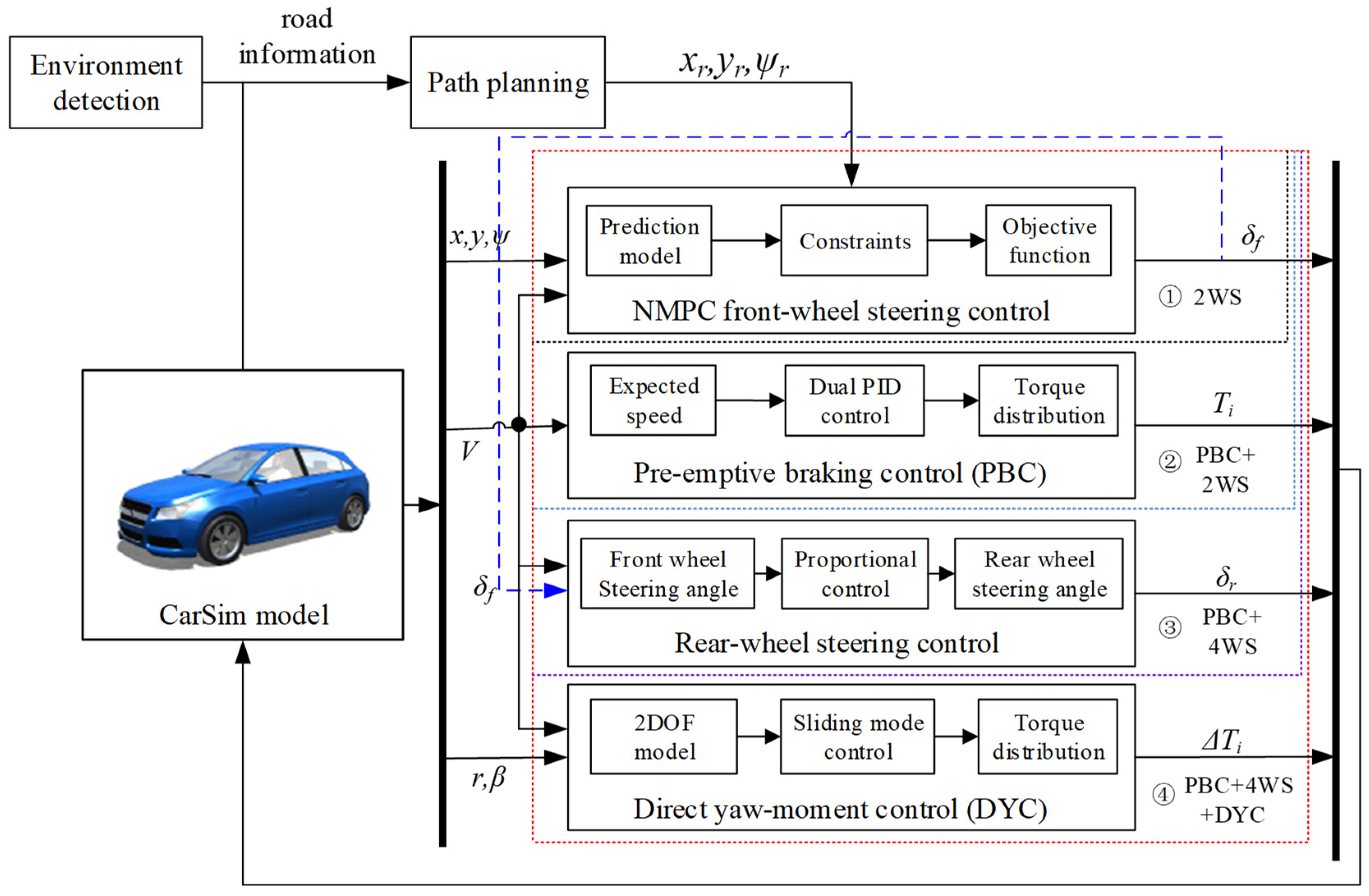
To address the aforementioned issues, this article proposes an integrated control method including pre-emptive braking control for emergency collision avoidance. A linear model predictive control (LMPC) is used to obtain the front wheel steering angle, and a simple proportional control method is employed for 4WS. Based on a two-degrees-of-freedom vehicle dynamics model, the maximum stable vehicle speed during collision avoidance can be determined. If the actual vehicle speed exceeds the maximum stable vehicle speed, braking action will be applied to the vehicle with a double PID controller for longitudinal motion control. In addition, direct yaw moment control is employed to further improve the stability of the vehicle during collision avoidance. To verify the effectiveness of the proposed collision avoidance strategy, a vehicle dynamics model and a typical double lane change collision avoidance scenario is established using CarSim software 2020 version, and the control algorithm is formulated using Matlab/Simulink R2022b version for joint simulation. Four different control systems are subjected to comparative testing: ① 2WS, ② pre-emptive braking control (PBC) + 2WS, ③ PBC + 4WS, and ④ PBC + 4WS + DYC.

1.4. Structure Overview

The subsequent sections of this article are outlined as follows: Section 2 introduces control objectives, examines the challenges encountered during emergency collision avoidance. Section 3 presents the control system design. Section 4 carries out a comparative simulation analysis of the four control systems under the given scenario and presents the outcomes of this comparative study. Finally, in Section 5, a summary of the entire content is provided.

2. Control Strategies

2.1. Control Objectives

The objective of this section is to enable an autonomous vehicle to smoothly navigate through the emergency collision avoidance scenario (Figure 1), while ensuring the highest possible entry speed. Assuming the road information is known and the obstacle avoidance track dimensions are described in Table 1, experienced human drivers often rely on anticipation to decide whether to decelerate the vehicle or not. This article applies a similar anthropomorphic control strategy to autonomous vehicles. By the road information and vehicle dynamics model, it is easy to judge whether the autonomous vehicle will keep stable or not when passing through the road ahead at the current speed. If the vehicle speed is too high to maintain stability, the autonomous vehicle will be decelerated in advance to a level that allows safe negotiation of the road to avoid danger. Four-wheel steering control is used to track the planned trajectory in advance. The rear wheel steering angle is proportional to the front wheel steering angle, and the latter is derived by the linear model predictive control. To further improve the stability of the vehicle, we have also adopted DYC control to minimize the vehicle sideslip angle as much as possible.

2.2. Overall Control Framework

The decision logic for the autonomous vehicle is shown in Figure 2. If the vehicle speed is faster than the safe speed, which can be calculated by road information and vehicle dynamics model, the autonomous vehicle will be decelerated by the pre-emptive braking control system. Otherwise, the vehicle tracks the predetermined trajectory through 2WS or 4WS.
The overall control framework of the proposed control system is shown in Figure 3. It consists of three parts: (1) path planning by the 5th-degree polynomial; (2) control system; and (3) vehicle CarSim model. Four different control systems are designed for comparison: ① front-wheel steering control (2WS), ② pre-emptive braking control (PBC) + 2WS, ③ PBC + 4WS, and ④ PBC + 4WS + DYC. The 2WS system tracks the predetermined trajectory by linear model predictive control. As for the 4WS system, the rear wheel steering angle is proportional to the front wheel steering angle that is obtained by 2WS. The safe speed can be calculated by the 2-DOF vehicle model for the pre-emptive braking control system. It adapts dual PID control to make the vehicle travel at the desired speed. The sliding model controller is used to allow the active yaw moment through the 2-DOF reference model.

3. Control System Design

3.1. Path Planning

A quintic polynomial is used for the collision avoidance path planning. It can be expressed as follows [36]:
y L = 10 a b 3 x L 3 15 a b 4 x L 4 + 6 a b 5 x L 5
where yL is the vehicle’s lateral displacement; xL is the vehicle’s longitudinal displacement; a is lane width; b is the longitudinal displacement of the vehicle during a lane change.

3.2. Vehicle Dynamics Modeling

Vehicle dynamic models can be classified into various types [37]. A 2-DOF vehicle single track dynamic model is adapted in this article, as shown in Figure 4. It is assumed that the center of gravity is on ground level and the steering angle on front axle and rear axle is small. The equations of motion of the lateral and yaw motions are given by:
m V ( β ˙ + r ) = F y f + F y r I z r ˙ = F y f l f F y r l r
If the lateral force produced by the tire is proportional to the tire sideslip angle, and the steering input is only the front wheel, the equations for lateral and yaw motion can be expressed as:
m V ( β ˙ + r ) = 2 C f ( δ f L f r V β ) + 2 C r ( L f r V β ) I z r ˙ = 2 C f l f ( δ f L f r V β ) 2 C r l r ( L f r V β )
The variables are defined as follows: V represents the vehicle speed; δf represents the front wheel steering angle; β represents the vehicle’s sideslip angle; r represents the yaw rate; Fyf and Fyr represent the front and rear lateral forces, respectively; lf and lr represent the distances from the center of mass to the front and rear axles, respectively; m is the vehicle mass; Iz is the yaw moment of inertia.

3.3. Pre-Emptive Braking Controller

3.3.1. Safe Speed

There exists a certain relationship between the lateral deviation of the vehicle actual displacement and the tracking displacement, as well as the vehicle speed. Given the road curvature and adhesion coefficient, it is possible to solve for the safe speed corresponding to the maximum lateral deviation.
Assuming the vehicle runs on a curve road with curvature R at a constant speed, Equation (3) can be expressed as Equation (4). By conversion, Equations (5)–(7) can be obtained [9].
y ˙ c = V ( β + ψ ) y ¨ c = V ( β ˙ + ψ ˙ ) ψ ˙ = r ψ ¨ = r ˙
Δ y ˙ c V Δ ψ = y ˙ c V ψ y ¨ c = Δ y ¨ c + ρ V 2 ψ ˙ = Δ ψ ˙ + ρ V ψ ¨ = Δ ψ ¨ + ρ ˙ V
[ ψ ¨ ψ ˙ y ¨ c y ˙ c ] = [ a 11 a 12 a 13 0 1 0 0 0 a 31 a 32 a 33 0 0 0 1 0 ] [ ψ ˙ ψ y ˙ c y c ] + [ b 11 0 b 31 0 ] δ f
[ Δ ψ ¨ Δ ψ ˙ Δ y ¨ c Δ y ˙ c ] = [ a 11 a 12 a 13 0 1 0 0 0 a 31 a 32 a 33 0 0 0 1 0 ] [ Δ ψ ˙ Δ ψ Δ y ˙ c Δ y c ] + [ b 11 0 b 31 0 ] δ f + [ c 11 c 12 0 0 0 c 32 0 0 ] [ ρ ˙ ρ ]
where yc is lateral displacement; ψ is yaw angle; Δyc is the relative lateral displacement; Δψ is the relative yaw angle.
a 11 = l f 2 C f + l r 2 C r I z V , a 12 = l f C f l r C r I z , a 13 = l r C r l f C f I z V
a 31 = l r C r l f C f m V , a 32 = C f + C r m , a 33 = C f + C r m V
b 11 = l f C f I z , b 31 = C f m , c 11 = V , c 12 = a 11 V , c 32 = V 2 + a 31 V
Through calculation, the relation of the safe speed can be obtained as (8).
V r = L μ C r m L f [ l r 1 l f C f l r C r { l f C f h R Δ y c ( l f 2 C f + l r 2 C r ) } ]
Assuming a maximum lateral deviation of 0.55 m, the safe speeds for the vehicle double lane change emergency avoidance maneuver on low friction (µ = 0.3), medium friction (µ = 0.6), and high friction (µ = 1.0) roads are 24.7 km/h, 35 km/h, and 45 km/h, respectively.

3.3.2. Dual PID Longitudinal Motion Control

This study adopts a dual PID controller for the vehicle longitudinal motion control, as shown in Figure 5. Where Sr, Vr, ar denote the desired position, desired speed, and desired acceleration, respectively; S, V, a denote the actual position, actual velocity, and actual acceleration of the vehicle, respectively; Vd, ad denote the adjusted speed and acceleration, respectively. The first PID controller adjusts the speed by the position error e1. The second PID controller adjusts the acceleration by controlling the velocity error e2. The torque is then transmitted to the motor through the torque distribution. The differential equations of the PID controller are expressed as follows in Equations (9) and (10).
V d = K p 1 [ ( S r S ) + 1 T i 1 0 t ( S r S ) d t + T d 1 d ( S r S ) d t ]
a d = K p 2 [ ( V d + V r V ) + 1 T i 2 0 t ( V d + V r V ) d t + T d 2 d ( V d + V r V ) d t ]
where Kp1, Ti1, and Td1 represent the proportional coefficient, integral time constant, and derivative time constant of the speed compensation PID, with values of 3, 10, and 1, respectively. Kp2, Ti2, and Td2 denote the proportional coefficient, integral time constant, and derivative time constant of the acceleration compensation PID, with values of 9.5, 0.13, and 1, respectively. The PID tuning process can be referred to in [38].

3.3.3. Torque Distribution

Hub motors are used to control the vehicle driving or braking torque. The permanent magnet brushless DC motor model is simplified to a second-order system as Equation (11). The vehicle driving (braking) torque is obtained by vehicle acceleration and distributed to four wheels proportional to the axle load. The specific calculation can be referred to in Section 3.6.3.
G ( s ) = T m T m * = 1 2 ζ 2 s 2 + 2 ζ s + 1
where T*m is the target torque calculated by the controller; Tm is the output torque of the wheel motor; motor characteristic parameter ζ = 0.05.

3.4. 2WS Controller

In this study, a model predictive control algorithm is selected for the 2WS controller design. MPC is known for its ability to perform predictive control and handle constraint control problems, which can ensure accurate lateral tracking control by optimizing the real-time slip angle of the front wheel [39].
The state equation is expressed as Equation (12):
x ˙ = A x + B u y = C x + D u
where the state vector is x = [ Y , ψ , v y , r ] T , the control input u = [ δ f ] T , the control output y = [ ψ , Y ] T .
A = [ 0 V 1 0 0 0 0 1 0 0 C f + C r m V l r C r l f C f m V V 0 0 l r C r l f C f I z V l f 2 C f + l r 2 C r I z V ] , B = [ 0 0 C f m l f C f I z ] , C = [ 0 1 0 0 1 0 0 0 ] , D = [ 0 0 ]
For nonlinear model predictive control problems, fast optimization is crucial, especially in real-time applications in intelligent vehicles [40,41]. To improve the optimization speed, the nonlinear predictive model is often transformed into a linear model to reduce complexity and enhance computational efficiency. The linear motion programming model is obtained by linearizing the equation of state, as shown in Equation (13).
ξ ˙ = A k ξ + B k u
where Ak and Bk are the Jacobian matrix relative to the state variables and the control input, respectively.
In order to achieve the vehicle closest possible approximation to the desired path, the design problem of the MPC path tracking controller is formulated as a general optimization problem. The objective is to find an optimal control input vector that minimizes the tracking error between the predicted outputs and the reference values. Since intelligent vehicles may encounter sudden changes in control variables during operation, it is necessary to incorporate relaxation factors in the objective function. Therefore, the objective function must satisfy Equation (14).
min [ J ( ξ ( k ) , Δ U ( k ) ] = i = 1 N p y ( k + i | k ) y r ( k + i | k ) Q 2 + i = 0 N c 1 Δ u ( k + i | k ) R 2 + ρ ε 2
where Np, Nc denote the prediction time domain and the control time domain, respectively; Q denotes the state weighting matrix; R denotes the control input weighting matrix; ε denotes the relaxation factor; ρ denotes the relaxation factor weight coefficient.

3.5. Four-Wheel Steering Control

A simple proportional control is adopted for the four-wheel steering controller design. The rear wheel steering angle is adjusted according to the proportional coefficient Kff as shown in Equation (15). And the front wheel steering angle is obtained by the 2WS.
δ r = K f f δ f
where K f f = l r m l f C r L V 2 l f m l r C f L V 2 .

3.6. Direct Yaw-Moment Control

To enhance the vehicle’s handling stability during emergency collision avoidance, this study employs a sliding mode variable structure control approach to obtain the active yaw moment. The yaw rate and the sideslip angle in the 2-DOF dynamic model are used as the desired reference values. The additional yaw moment control input is determined based on the deviation between the two variables.

3.6.1. Expected Reference Value

The ideal sideslip angle and yaw rate of the reference model are shown in Equation (16). Since the maximum lateral acceleration that the vehicle can achieve is limited by the road friction, the constraints are shown as Equation (17). The reference values of the sideslip angle and yaw rate are shown in Equation (18) [42].
β d = b / l + m a V 2 / ( l 2 C r ) 1 + K v V 2 r d = V l + K v V 2 δ f
| β | | arctan ( 0.02 μ g ) | | r | 0.85 μ g V
β r e f = min { | β d | , arctan ( 0.02 μ g ) } sgn ( β d ) r r e f = min { | r d | , 0.85 μ g V } sgn ( r d )
where the understeering gradient is K v = m l ( l r C f l f C r ) .

3.6.2. Sliding Mode Controller

The linear sliding mode surface is used in this article [43,44]. The sliding surface is defined as Equation (19). By differential transformation, it is easy to obtain Equation (20). The exponential reaching rate is selected to constrain the trajectory of the system, as shown in Equation (21). The additional yaw moment can be obtained as Equation (22). In order to smooth the signal, sgn(s) is replaced by the saturation function sat(s) as shown in Equation (23).
s = ( r r r e f ) + λ ( β β r e f )
s ˙ = ( r ˙ r ˙ r e f ) + λ ( β ˙ β ˙ r e f )
s ˙ = ε sgn ( s ) K s
Δ M = ( l f C f l r C r ) β l f 2 C f + l r 2 C r V r + l f C f δ f l r C r δ r I z ( ε sgn ( s ) + K s ) + r ˙ r e f
sat ( s ) = { 1 s > Δ t s Δ t | s | Δ t 1 s < Δ t
where λ represents the weight coefficient of the deviation of the state quantity, which is set to 10. ε and K are set to 1 and 0.1. The boundary layer thickness Δt is set to 0.05.

3.6.3. Torque Distribution

The driving or brake torque can be obtained according to the additional active yaw moment, as shown in Equation (24).
T f l = m g l r a x h g 2 m g l ( F x 2 Δ M B / 2 ) R T f r = m g l r a x h g 2 m g l ( F x 2 + Δ M B / 2 ) R T r l = m g l f + a x h g 2 m g l ( F x 2 Δ M B / 2 ) R T r r = m g l f a x h g 2 m g l ( F x 2 + Δ M B / 2 ) R

4. Simulation and Analysis

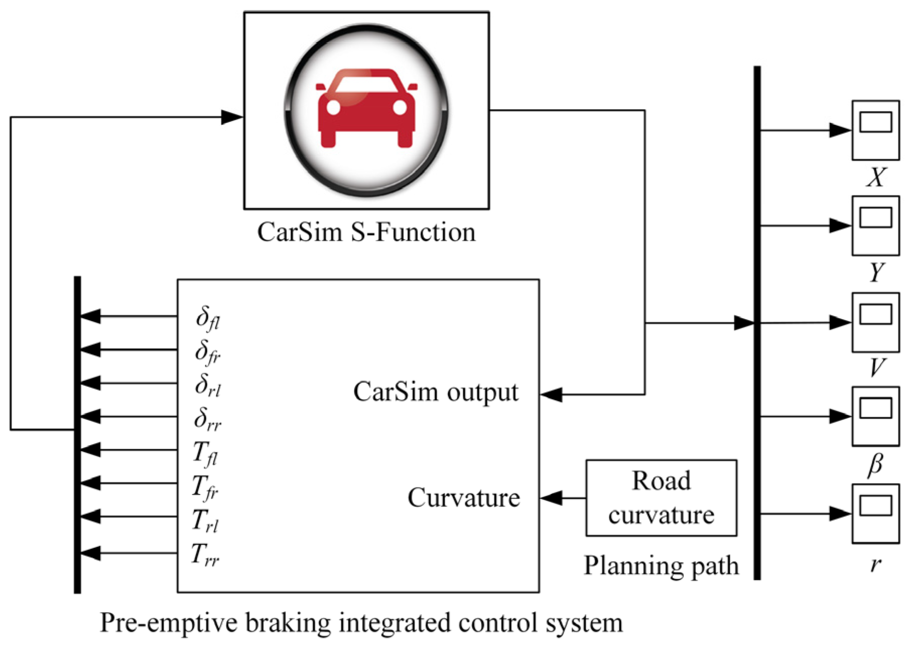
To validate the effectiveness of the proposed integrated collision avoidance control system, a joint simulation model is built through CarSim and Matlab/Simulink for the double lane change emergency collision avoidance, as shown in Figure 6. A high-fidelity C-class vehicle model provided in CarSim is used for simulation. The specific model parameters and controller parameters are listed in Table 2. The model parameters include vehicle mass, the position of center of mass, and tire lateral stiffness, etc. The controller parameters include controller sample time, size of the prediction horizon and the control horizon etc.
Four different control systems as listed in Table 3 are compared on low, medium, and high friction roads, respectively. The controller consists of a pre-emptive braking controller for longitudinal motion control and a 2WS controller for path tracking control. When the vehicle speed exceeds the safe speed, pre-emptive braking is applied to the autonomous vehicle. Additionally, the 4WS and DYC systems are adopted to enhance stability during the emergency collision avoidance.

4.1. Low Friction (µ = 0.3)

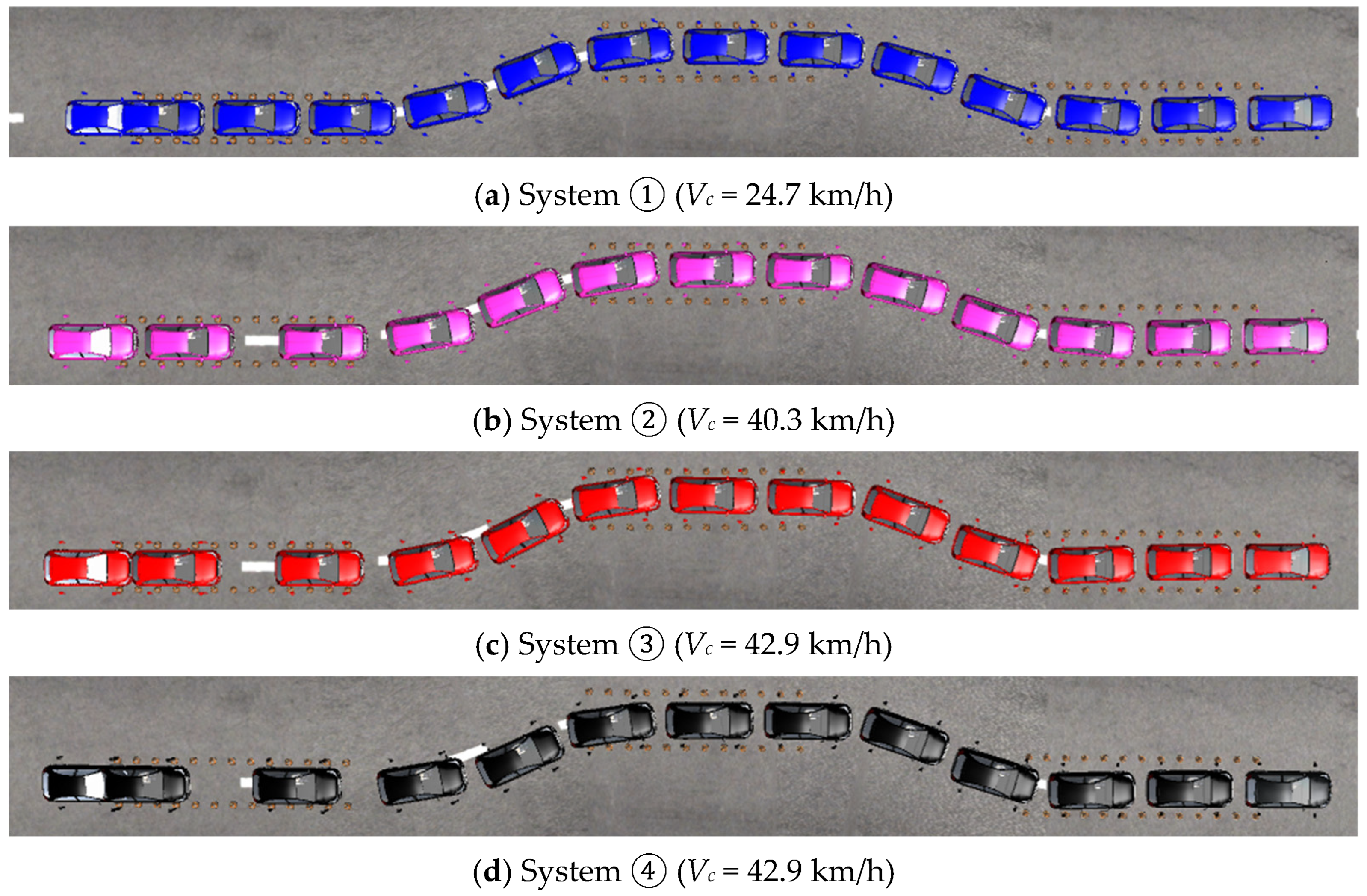
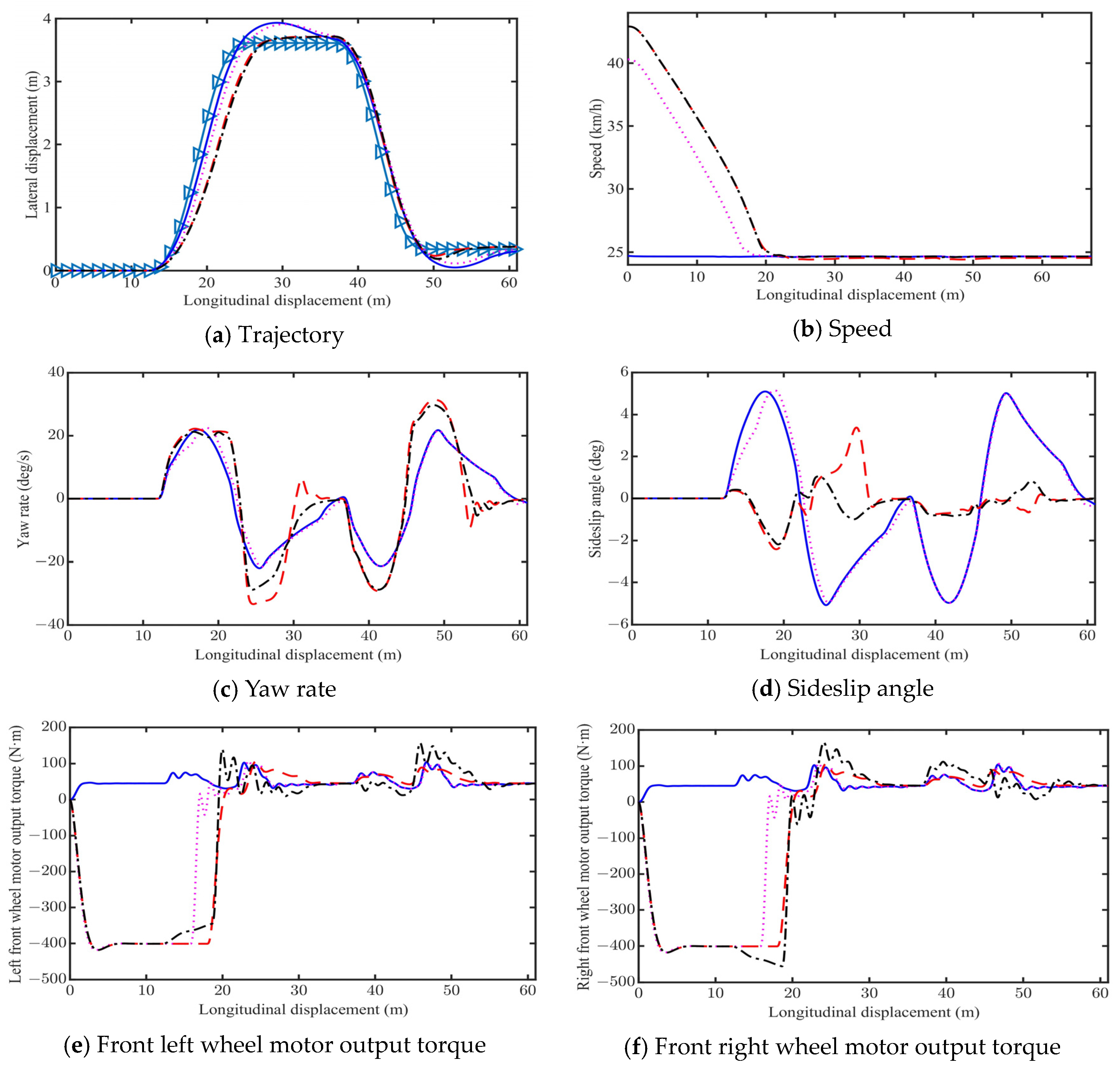
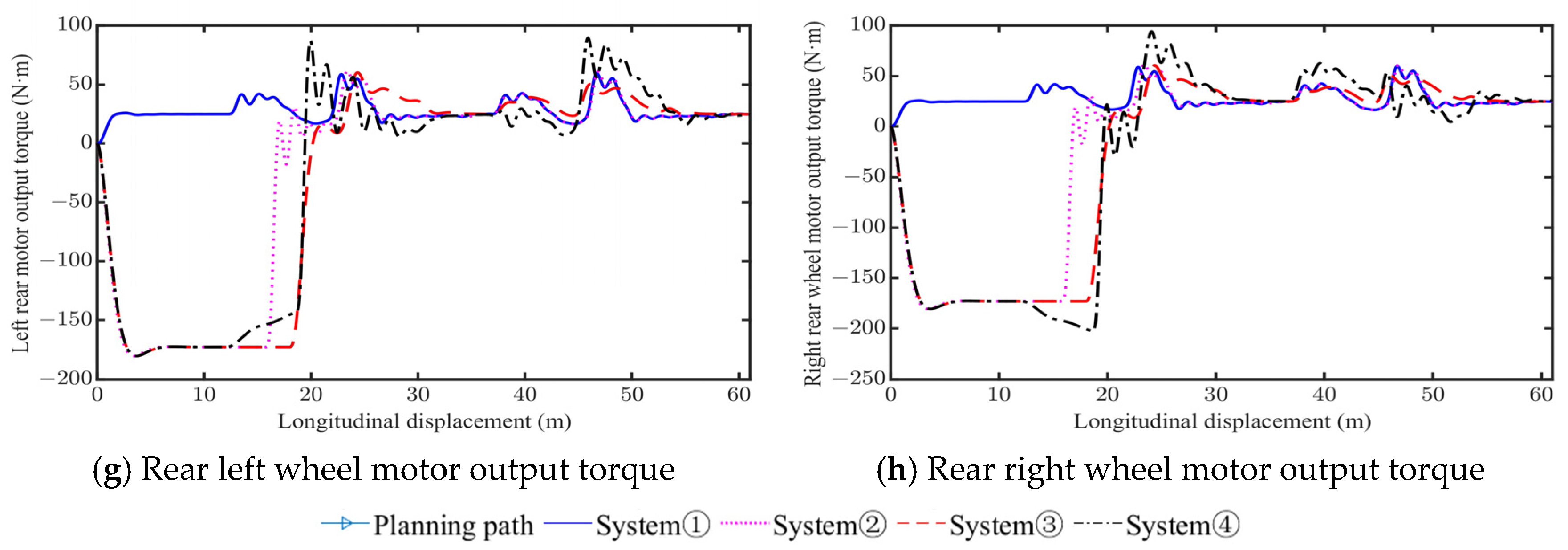
Figure 7 shows the CarSim model phantom on a low friction road by the four control systems above. The simulation results are shown in Figure 8, in which Figure 8a–h are vehicle trajectory, speed, yaw rate, sideslip angle, motor output torque of front left, front right, rear left, and rear right wheels, respectively.
Table 4 presents the main evaluation indexes under the given scenario, including the vehicle entry speed Vc, final speed Vf, the peak value of vehicle sideslip angle |βmax|, and the peak value of yaw rate |r|. The simulation results show that, compared with System ①, the maximum safe speed by System ② is increased by 15.6 km/h, reaching up to 40.3 km/h. The maximum safe speeds of System ③ and System ④ are very close, both reaching 42.9 km/h. Compared with System ②, the |βmax| of System ③ and System ④ are reduced by 1.75° and 2.95°, respectively, indicating the vehicle stability of System ④ is the best.

4.2. Medium Friction (µ = 0.6)

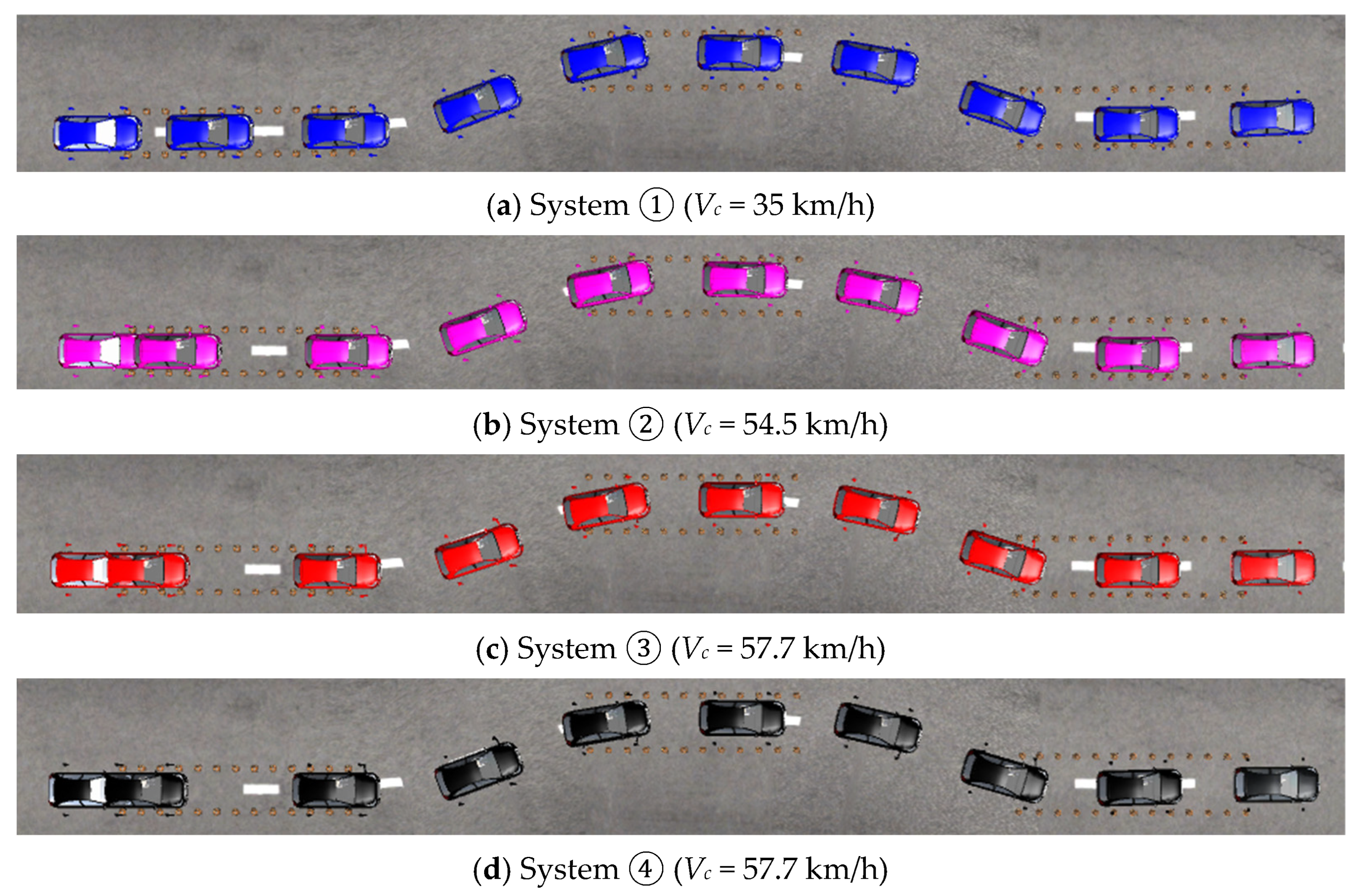
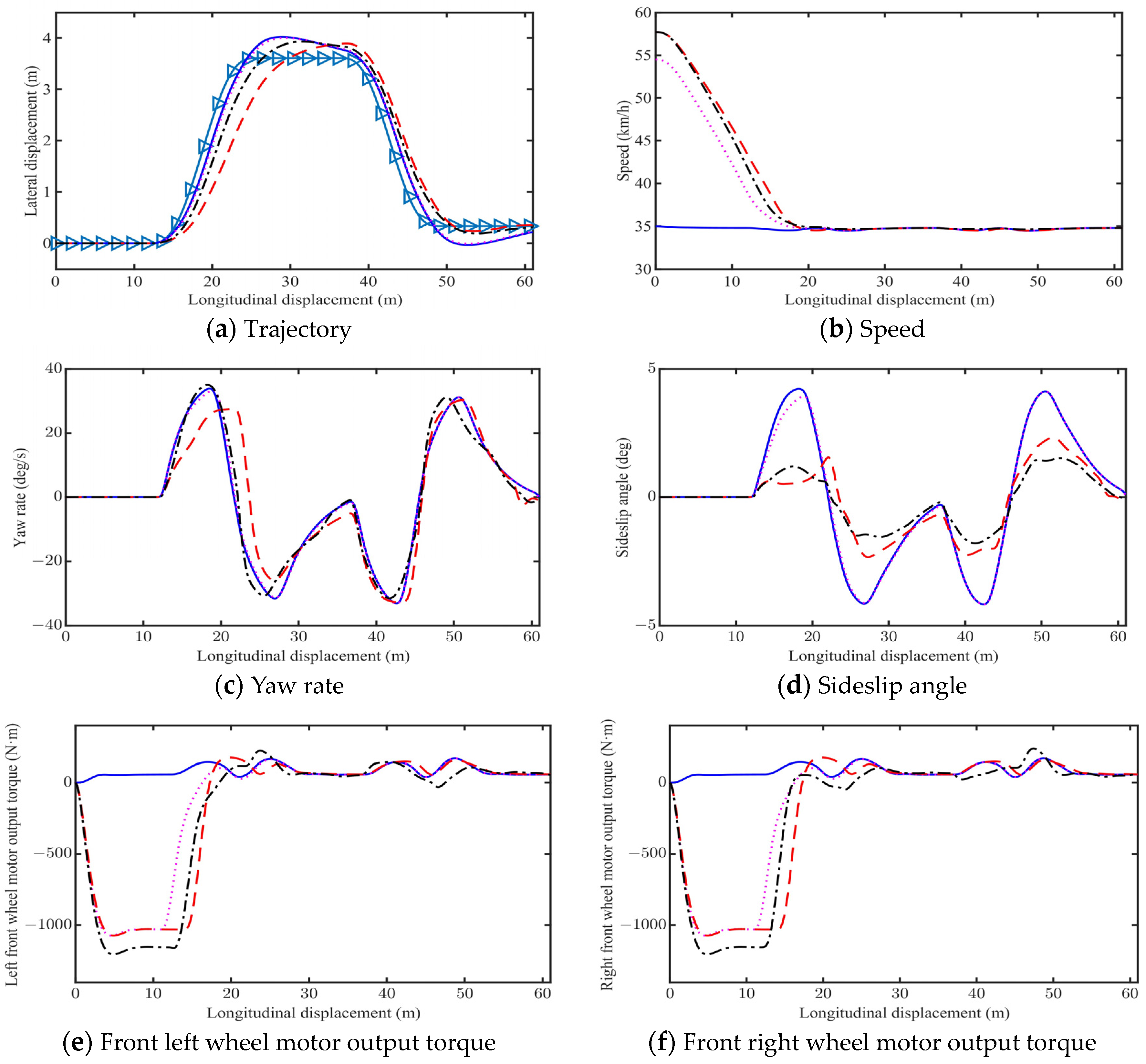
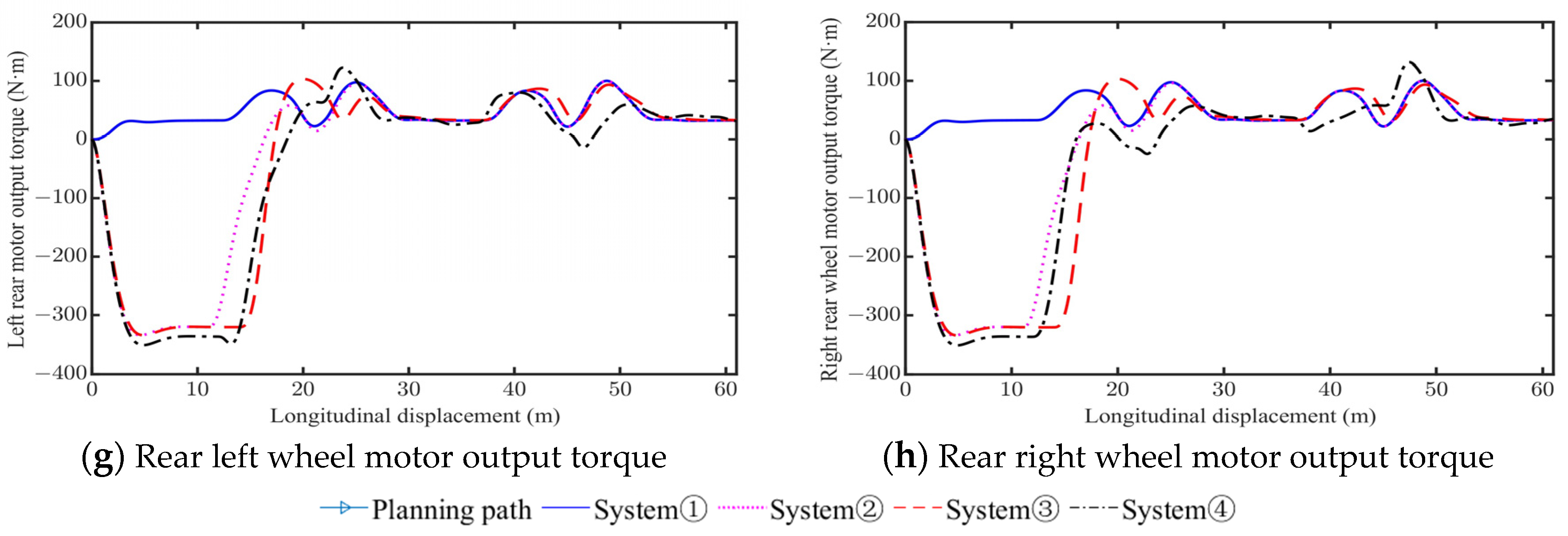
Figure 9 shows the CarSim model phantom on a medium friction road by the four control systems above. Figure 10a–h are vehicle trajectory, speed, yaw rate, sideslip angle, motor output torque of front left, front right, rear left, and rear right wheels, respectively. Table 5 presents the main evaluation indexes. Compared with the System ①, the maximum safe speed of System ②, System ③, and System ④ increases by 19.5 km/h, 22.7 km/h, and 22.7 km/h, respectively. Similarly, System ④ has the best stability, with a maximum sideslip angle of 1.79°. System ① has the worst stability, with a maximum sideslip angle of about 4°.

4.3. High Friction (µ = 1.0)

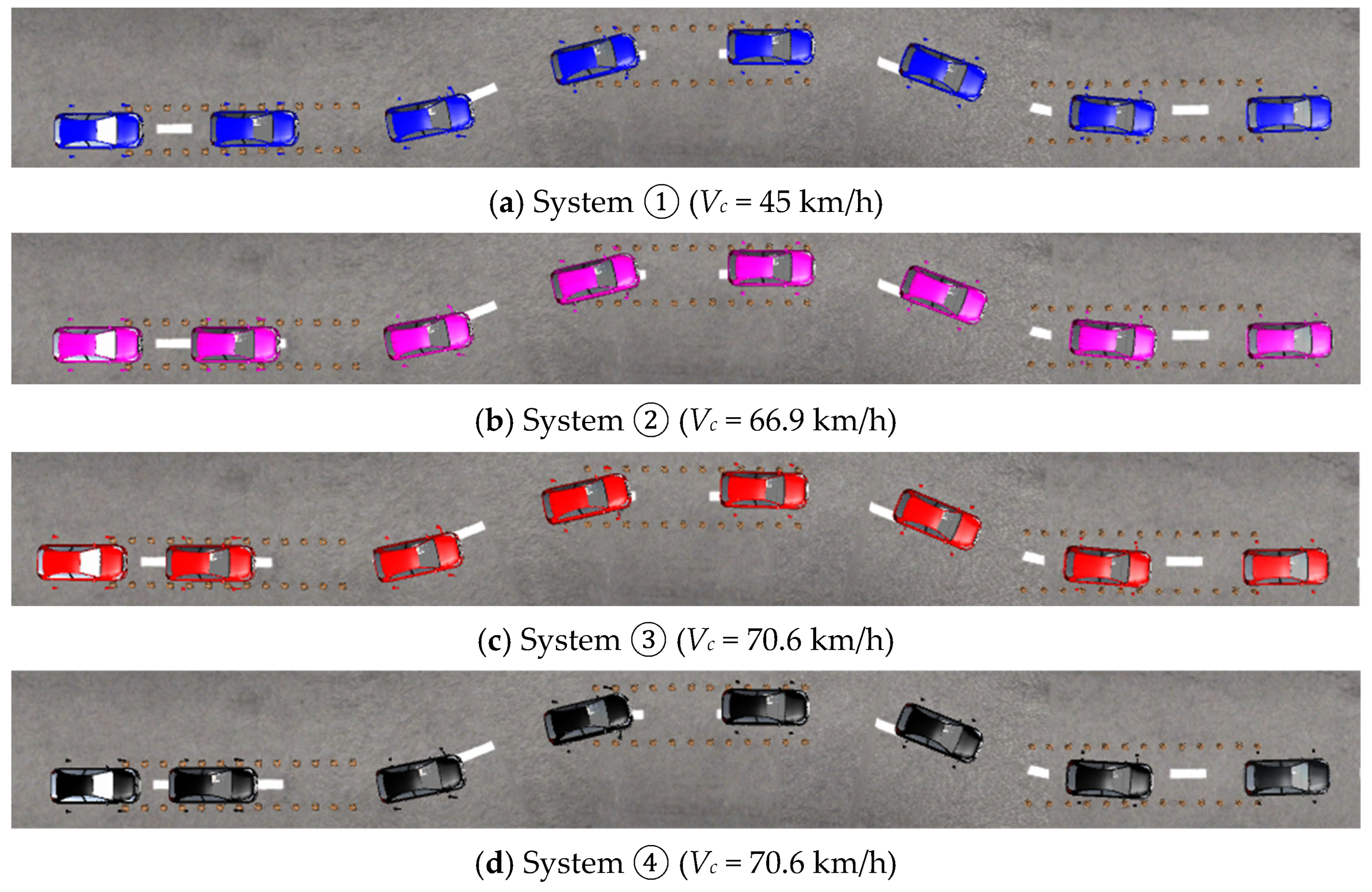
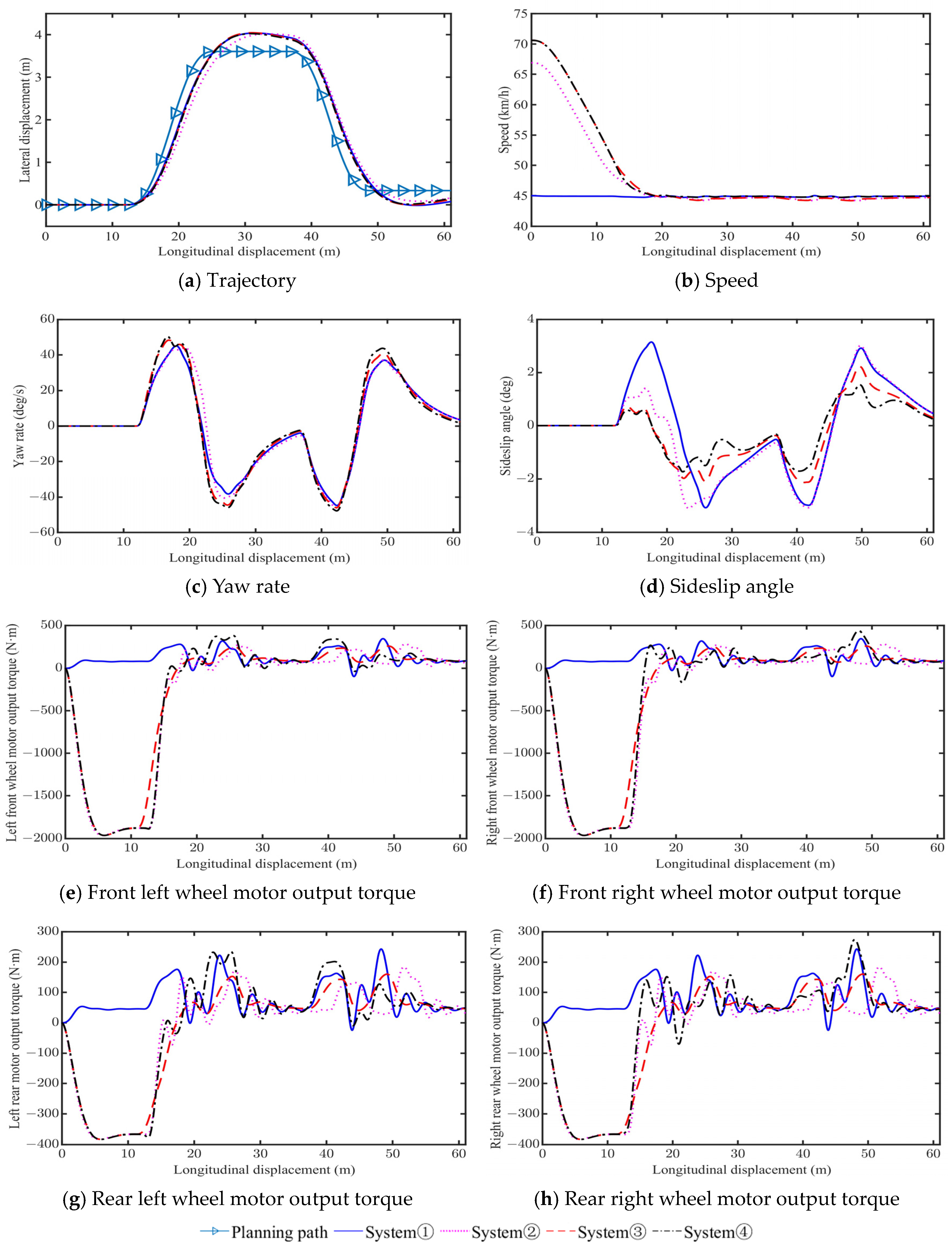
Figure 11 shows the CarSim model phantom on a high friction road by the four control systems above. Figure 12a–h are vehicle trajectory, speed, yaw rate, sideslip angle, motor output torque of front left, front right, rear left, and rear right wheels, respectively. Table 6 presents the main evaluation indexes. Compared with the System ①, the maximum safe speed of System ②, System ③, and System ④ increases by 21.9 km/h, 25.6 km/h, and 25.6 km/h, respectively. Similarly, System ④ has the best stability, with a maximum sideslip angle of 1.74°. System ① has the worst stability, with a maximum sideslip angle of 3.15°.
According to the aforementioned simulation results on different friction roads, the effectiveness of the four control systems can be clearly compared. For System ①, the vehicle only utilizes 2WS, resulting in the lowest safe speed for emergency collision avoidance. For System ②, the implementation of a pre-emptive braking control significantly increases the safe speed, but the stability improvement is limited. In contrast, System ③ demonstrates advantages in enhancing both the safe speed and vehicle stability through the incorporation of 4WS. Furthermore, System ④ with DYC exhibits the best integrated performance.

5. Conclusions

This paper presents an integrated control method including pre-emptive braking control for emergency collision avoidance. It aims to prevent vehicle instability by adjusting the vehicle speed to a reasonable value, while enhancing the vehicle stability through 4WS and DYC. The effectiveness of the proposed control system is validated through a joint simulation of Matlab/Simulink and CarSim under a double lane change emergency collision avoidance scenario. To address the problem, four different control systems are constructed for comparison: ① 2WS, ② pre-emptive braking control (PBC) + 2WS, ③ PBC + 4WS, and ④ PBC + 4WS + DYC. The following conclusions can be drawn:
(1)
System ①, which adopts 2WS alone, exhibits poor vehicle stability during emergency collision avoidance.
(2)
Compared to System ①, the maximum stable vehicle speeds of System ② with PBC increase by 63.15%, 55.71%, and 48.67% on low, medium, and high friction road, respectively.
(3)
The maximum stable vehicle speeds of System ③ and System ④ are very close. Compared to System ①, the maximum stable vehicle speeds of System ③ and system ④ increase by 73.7%, 64.9%, and 56.9% on low, medium, and high friction road, respectively.
(4)
Compared to System ③, System ④ with DYC achieves a reduction in vehicle sideslip angle by 35.5%, 23.5%, and 22.0% on low, medium, and high friction road, respectively.
This study is limited to the given scenarios of constant road friction. Future investigation should be focused on the influences of different scenarios and variable road friction on vehicle stability and safety. In addition, experimental verification is also an important research task for the future.

Author Contributions

Conceptualization, F.L.; methodology, formal analysis, F.L. and X.W.; software, validation, X.W.; writing, F.L. and X.W.; supervision, project administration, F.L. All authors have read and agreed to the published version of the manuscript.

Funding

This work was supported by the Science and Technology Research Program of Chongqing Education Commission of China (202101105).

Institutional Review Board Statement

Not applicable.

Informed Consent Statement

Not applicable.

Data Availability Statement

Data is contained within the article.

Conflicts of Interest

The authors declare no conflict of interest.

Abbreviations

DOFDegrees of freedom
2WSFront-wheel steering
4WSFour-wheel steering
DYCDirect yaw moment control
LMPCLinear model predictive control
NMPCNonlinear model predictive control
PIDProportional integral derivative controller
PBCPre-emptive braking control

References

  1. Editorial Department of China Journal of Highway and Transport. Review on China’s automotive engineering research progress: 2017. China J. Highw. Transp. 2017, 30, 1–197. [Google Scholar]
  2. Zarkadis, K.; Velenis, E.; Siampis, E.; Longo, S. Predictive torque vectoring control with active trail-braking. In Proceedings of the 2018 European Control Conference, Limassol, Cyprus, 12–15 June 2018; pp. 569–574. [Google Scholar]
  3. Parra, A.; Tavernini, D.; Gruber, P.; Sorniotti, A.; Zubizarreta, A.; Pérez, J. On pre-emptive vehicle stability control. Veh. Syst. Dyn. 2022, 60, 2098–2123. [Google Scholar] [CrossRef]
  4. Abe, M.; Ohkubo, N.; Kano, Y. A direct yaw moment control for improving limit performance of vehicle handling-comparison and cooperation with 4WS. Veh. Syst. Dyn. 1996, 25, 3–23. [Google Scholar] [CrossRef]
  5. Yim, S. Comparison among active front, front independent, 4-wheel and 4-wheel independent steering systems for vehicle stability control. Electronics 2020, 9, 798. [Google Scholar] [CrossRef]
  6. Park, J.Y.; Na, S.; Cha, H.; Yi, K. Direct yaw moment control with 4WD torque-vectoring for vehicle handling stability and agility. Int. J. Automot. Technol. 2022, 23, 555–565. [Google Scholar] [CrossRef]
  7. Sun, P.; Trigell, A.S.; Drugge, L.; Jerrelind, J. Energy efficiency and stability of electric vehicles utilizing direct yaw moment control. Veh. Syst. Dyn. 2022, 60, 930–950. [Google Scholar] [CrossRef]
  8. Huang, C.; Lai, F. Pre-emptive braking control for stability improvement of autonomous vehicles on a curved road based on vehicle-to-everything technology. SAE Int. J. Commer. Veh. 2023, 16, 3–18. [Google Scholar] [CrossRef]
  9. Kojima, T.; Raksincharoensak, P. Environment-on-board predictive braking control functions for autonomous driving during sudden changes in the road friction coefficient on sharp curves. Int. J. Automot. Technol. 2022, 23, 451–460. [Google Scholar] [CrossRef]
  10. Guastadisegni, G.; So, K.M.; Parra, A.; Tavernini, D.; Montanaro, U.; Gruber, P.; Sorniotti, A. Vehicle stability control through pre-emptive braking. Int. J. Automot. Technol. 2023, 24, 347–365. [Google Scholar] [CrossRef]
  11. Zhou, H.; Gao, J.; Liu, H. Vehicle speed preview control with road curvature information for safety and comfort promotion. Proc. Inst. Mech. Eng. Part D J. Automob. Eng. 2021, 235, 1527–1538. [Google Scholar] [CrossRef]
  12. Hiraoka, T.; Nishihara, Q.; Kumamoto, H. Automatic path-tracking controller of a four-wheel steering vehicle. Veh. Syst. Dyn. 2009, 47, 1205–1227. [Google Scholar] [CrossRef]
  13. Lai, F.; Huang, C. Comparative study on tracking control methods for automatic emergency steering and collision avoidance of intelligent vehicles. China J. Highw. Transp. 2021, 34, 250–264. [Google Scholar]
  14. Liu, Q.; Gordon, T.; Rahman, S. Model-free autonomous control of four-wheel steering using artificial flow guidance. Veh. Syst. Dyn. 2023, 2023, 2276761. [Google Scholar] [CrossRef]
  15. Chen, T.; Chen, L.; Xu, X.; Cai, Y.; Sun, X. Simultaneous path following and lateral stability control of 4WD-4WS autonomous electric vehicles with actuator saturation. Adv. Eng. Softw. 2019, 128, 46–54. [Google Scholar] [CrossRef]
  16. Xu, F.X.; Liu, X.H.; Chen, W.; Zhou, C.; Cao, B.W. Improving handling stability performance of four-wheel steering vehicle based on the H2/H∞ robust control. Appl. Sci. 2019, 9, 857. [Google Scholar] [CrossRef]
  17. Cheng, S.; Li, L.; Guo, H.Q.; Chen, Z.G.; Song, P. Longitudinal collision avoidance and lateral stability adaptive control system based on MPC of autonomous vehicles. IEEE Trans. Intell. Transp. Syst. 2019, 21, 2376–2385. [Google Scholar] [CrossRef]
  18. Hu, C.; Wang, R.; Yan, F.; Chen, N. Output constraint control on path following of four-wheel independently actuated autonomous ground vehicles. IEEE Trans. Veh. Technol. 2015, 65, 4033–4043. [Google Scholar] [CrossRef]
  19. Yim, S. Preview controller design for vehicle stability with V2V communication. IEEE Trans. Intell. Transp. Syst. 2016, 18, 1497–1506. [Google Scholar] [CrossRef]
  20. Wang, Z.; Montanaro, U.; Fallah, S.; Sorniotti, A.; Lenzo, B. A gain scheduled robust linear quadratic regulator for vehicle direct yaw moment control. Mechatronics 2018, 51, 31–45. [Google Scholar] [CrossRef]
  21. Xie, X.; Jin, L.; Baicang, G.; Shi, J. Vehicle direct yaw moment control system based on the improved linear quadratic regulator. Ind. Robot Int. J. Robot. Res. Appl. 2021, 48, 378–387. [Google Scholar] [CrossRef]
  22. Tahami, F.; Farhangi, S.; Kazemi, R. A fuzzy logic direct yaw-moment control system for all-wheel-drive electric vehicles. Veh. Syst. Dyn. 2004, 41, 203–221. [Google Scholar] [CrossRef]
  23. Boada, B.L.; Boada, M.J.L.; Diaz, V. Fuzzy-logic applied to yaw moment control for vehicle stability. Veh. Syst. Dyn. 2005, 43, 753–770. [Google Scholar] [CrossRef]
  24. Li, H.M.; Wang, X.B.; Song, S.B.; Li, H. Vehicle control strategies analysis based on PID and fuzzy logic control. Procedia Eng. 2016, 137, 234–243. [Google Scholar] [CrossRef]
  25. Ahmed, A.A.; Abunada, A.R. Vehicle yaw rate control based on fuzzy PID control technology. J. Adv. Res. Mech. Eng. Technol. 2018, 5, 17–23. [Google Scholar]
  26. Ding, S.; Liu, L.; Zheng, W.X. Sliding mode direct yaw-moment control design for in-wheel electric vehicles. IEEE Trans. Ind. Electron. 2017, 64, 6752–6762. [Google Scholar] [CrossRef]
  27. Zhang, H.; Liang, J.; Jiang, H.; Cai, Y.; Xu, X. Stability research of distributed drive electric vehicle by adaptive direct yaw moment control. IEEE Access 2019, 7, 106225–106237. [Google Scholar] [CrossRef]
  28. Liu, D.; Huang, S.; Wu, S.; Fu, X. Direct yaw-moment control of electric vehicle with in-wheel motor drive system. Int. J. Automot. Technol. 2020, 21, 1013–1028. [Google Scholar] [CrossRef]
  29. Ahmed, A.A.; Jomah, O.S. Vehicle yaw rate control for lane change maneuver using fuzzy PID controller and neural network controller. In Proceedings of the 2020 IEEE 2nd International Conference on Electronics, Control, Optimization and Computer Science (ICECOCS), Kenitra, Morocco, 2–3 December 2020; pp. 1–6. [Google Scholar]
  30. Liu, J. Sliding Mode Control Using MATLAB; Elsevier Inc.: Beijing, China, 2017. [Google Scholar]
  31. Chiliveri, V.R.; Kalpana, R.; Kishan, D. Composite control design for in-wheel drive electric vehicle with unknown disturbances and input delay. In Proceedings of the 2022 IEEE International Conference on Power Electronics, Drives and Energy Systems (PEDES), Jaipur, India, 14–17 December 2022; pp. 1–6. [Google Scholar]
  32. Zhang, Y.; Hu, J.; Zhang, H.; Yi, X. Adaptive sliding mode control for uncertain nonlinear switched system under probabilistic replay attacks: The output feedback approach. Int. J. Adapt. Control Signal Process. 2023, 37, 2216–2232. [Google Scholar] [CrossRef]
  33. Tota, A.; Lenzo, B.; Lu, Q.; Sorniotti, A.; Gruber, P.; Fallah, S.; Velardocchia, M.; Galvagno, E.; Smet, J.D. On the experimental analysis of integral sliding modes for yaw rate and sideslip control of an electric vehicle with multiple motors. Int. J. Automot. Technol. 2018, 19, 811–823. [Google Scholar] [CrossRef]
  34. Zhu, Z.; Xia, Y.; Fu, M. Adaptive sliding mode control for attitude stabilization with actuator saturation. IEEE Trans. Ind. Electron. 2011, 58, 4898–4907. [Google Scholar] [CrossRef]
  35. Han, J.; Kim, T.; Oh, T.; Lee, S.; Cho, D. Effective disturbance compensation method under control saturation in discrete-time sliding mode control. IEEE Trans. Ind. Electron. 2020, 67, 5696–5707. [Google Scholar] [CrossRef]
  36. Zhang, S.; Simkani, M.; Zadeh, M.H. Automatic vehicle parallel parking design using fifth degree polynomial path planning. In Proceedings of the 2011 IEEE Vehicular Technology Conference (VTC Fall), San Francisco, CA, USA, 5–8 September 2011; pp. 1–4. [Google Scholar]
  37. Tan, B.; Chen, Y.; Liao, Q.; Zhang, B.; Zhang, N.; Xie, Q. A condensed dynamic model of a heavy-duty truck for optimization of the powertrain mounting system considering the chassis frame flexibility. Proc. Inst. Mech. Eng. Part D J. Automob. Eng. 2020, 234, 2602–2617. [Google Scholar] [CrossRef]
  38. Borase, R.P.; Maghade, D.K.; Sondkar, S.Y.; Pawar, S.N. A review of PID control, tuning methods and applications. Int. J. Dyn. Control 2021, 9, 818–827. [Google Scholar] [CrossRef]
  39. Rokonuzzaman, M.; Mohajer, N.; Nahavandi, S. Effective adoption of vehicle models for autonomous vehicle path tracking: A switched MPC approach. Veh. Syst. Dyn. 2023, 61, 1236–1259. [Google Scholar] [CrossRef]
  40. Allgower, F.; Findeisen, R.; Nagy, Z.K. Nonlinear model predictive control: From theory to application. J.-Chin. Inst. Chem. Eng. 2004, 35, 299–316. [Google Scholar]
  41. Peicheng, S.; Li, L.; Ni, X.; Yang, A. Intelligent vehicle path tracking control based on improved MPC and hybrid PID. IEEE Access 2022, 10, 94133–94144. [Google Scholar] [CrossRef]
  42. Chen, Z.; Wu, Y.; Li, F. Integrated control of differential braking and active aerodynamic control for improving high speed stability of vehicles. Int. J. Automot. Technol. 2020, 21, 61–70. [Google Scholar] [CrossRef]
  43. Silaa, M.Y.; Bencherif, A.; Barambones, O. A novel robust adaptive sliding mode control using stochastic gradient descent for PEMFC power system. Int. J. Hydrogen Energy 2023, 48, 17277–17292. [Google Scholar] [CrossRef]
  44. Utkin, V. Discussion aspects of high-order sliding mode control. IEEE Trans. Autom. Control 2016, 61, 829–833. [Google Scholar] [CrossRef]
Figure 1. Emergency collision avoidance scenario.
Applsci 13 13219 g001
Figure 2. Decision logic.
Applsci 13 13219 g002
Figure 3. Overall control framework.
Applsci 13 13219 g003
Figure 4. Vehicle 2 DOF model.
Applsci 13 13219 g004
Figure 5. Dual PID controller.
Applsci 13 13219 g005
Figure 6. Co-simulation framework.
Applsci 13 13219 g006
Figure 7. CarSim model phantom on a low friction road.
Applsci 13 13219 g007
Figure 8. Comparison of results on a low friction road.
Applsci 13 13219 g008aApplsci 13 13219 g008b
Figure 9. CarSim model phantom on a medium friction road.
Applsci 13 13219 g009
Figure 10. Comparison of results on a medium friction road.
Applsci 13 13219 g010aApplsci 13 13219 g010b
Figure 11. CarSim model phantom on a high friction road.
Applsci 13 13219 g011
Figure 12. Comparison of results on a high friction road.
Applsci 13 13219 g012
Table 1. Road description.
SectionLength (m)Width (m)
1122.329
213.56.219
3112.89
412.56.219
5123
Table 2. Model parameters and controller parameters.
SymbolParameter DescriptionValue
m/(kg)Vehicle mass1413
lf/mDistance from center of mass to front axle1.895
lr/mDistance from center of mass to rear axle1.015
Iz/(kg·m2)Moment of inertia about the Z axis1536.7
Cf/(N·m−1)Front axle lateral stiffness70,000
Cr/(N·m−1)Rear axle lateral stiffness35,000
NpSize of the prediction horizon20
NcSize of the control horizon5
TController sample time0.05
QState weighting matrixDiag (24, 16.8, 1, 1)
RControls input weighting matrixDiag (1, 1, 1)
ρRelaxation factor weight coefficient1000
Table 3. Different control systems.
Control SystemDescription
2WS
Pre-emptive braking control + 2WS
Pre-emptive braking control + 4WS
Pre-emptive braking control + 4WS + DYC
Table 4. Comparison of evaluation indicators on a low friction road.
Evaluation IndexSystem ①System ②System ③System ④
Vc (km/h)24.740.342.942.9
Vf (km/h)24.724.724.724.7
|βmax| (deg)5.095.133.382.18
|r| (deg/s)22.0222.4833.4629.65
Table 5. Comparison of evaluation indicators on a medium friction road.
Evaluation IndexSystem ①System ②System ③System ④
Vc (km/h)3554.557.757.7
Vf (km/h)35353535
|βmax| (deg)3.993.912.341.79
|r| (deg/s)33.8433.3232.3935.01
Table 6. Comparison of evaluation indicators on a high friction road.
Evaluation IndexSystem ①System ②System ③System ④
Vc (km/h)4566.970.670.6
Vf (km/h)45454545
|βmax| (deg)3.153.112.231.74
|r| (deg/s)45.1146.0648.3550.37
Disclaimer/Publisher’s Note: The statements, opinions and data contained in all publications are solely those of the individual author(s) and contributor(s) and not of MDPI and/or the editor(s). MDPI and/or the editor(s) disclaim responsibility for any injury to people or property resulting from any ideas, methods, instructions or products referred to in the content.