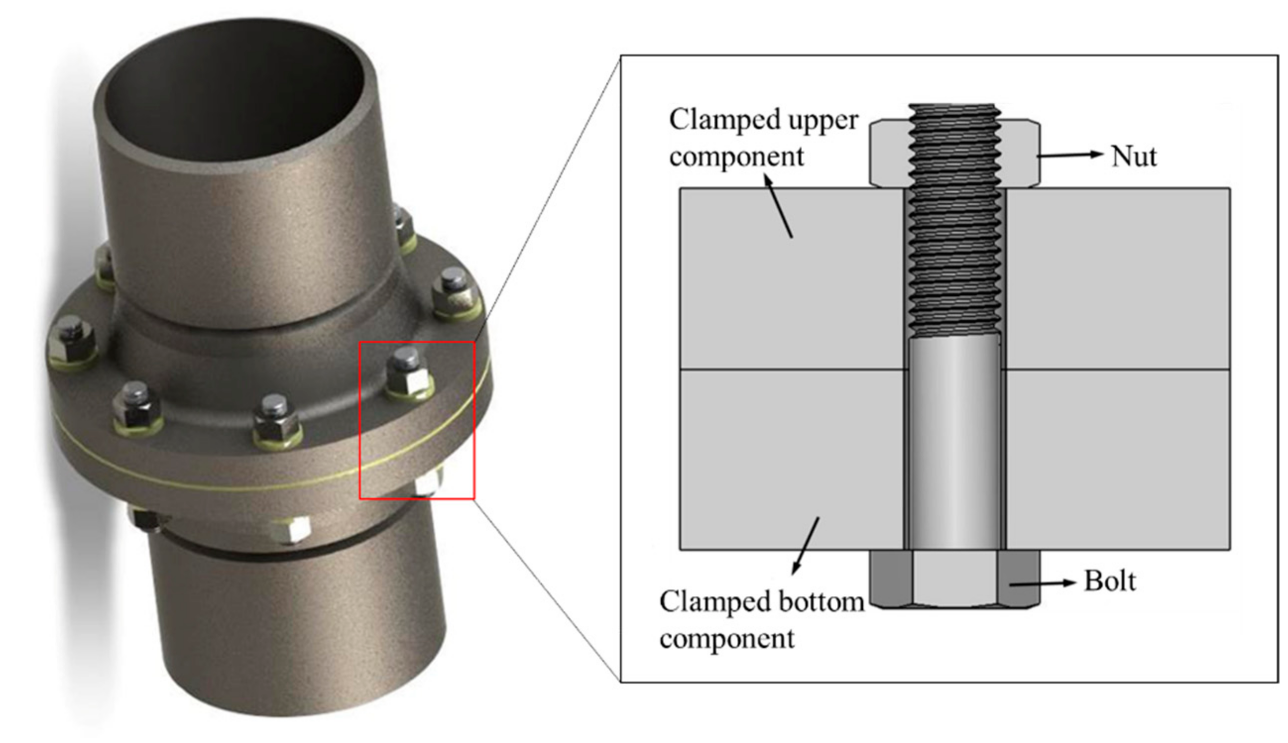
Figure 1.
Schematic representation of a bolted joint.
Figure 1.
Schematic representation of a bolted joint.
Figure 2.
Three types of anti-loosening bolted connections.
Figure 2.
Three types of anti-loosening bolted connections.
Figure 3.
Image of a wedge washer.
Figure 3.
Image of a wedge washer.
Figure 4.
Schematic representation of the second type of anti-loosening bolted connections: (a) wedge-locking nut; (b) variable-diameter nut.
Figure 4.
Schematic representation of the second type of anti-loosening bolted connections: (a) wedge-locking nut; (b) variable-diameter nut.
Figure 5.
Schematic representation of the third type of anti-loosening bolted connections: (a) eccentric double nut; (b) double-thread bolt engaged with two nuts.
Figure 5.
Schematic representation of the third type of anti-loosening bolted connections: (a) eccentric double nut; (b) double-thread bolt engaged with two nuts.
Figure 6.
Two-dimensional sketches of a regular bolted joint: (a) joint; (b) nut; (c) bolt.
Figure 6.
Two-dimensional sketches of a regular bolted joint: (a) joint; (b) nut; (c) bolt.
Figure 7.
Three-dimensional FEM of a regular bolted joint: (a) entire regular bolted joint; (b) sectional view of the threaded part.
Figure 7.
Three-dimensional FEM of a regular bolted joint: (a) entire regular bolted joint; (b) sectional view of the threaded part.
Figure 8.
Three-dimensional FEMs of different anti-loosening bolted connections: (a) plain washer; (b) wedge washer; (c) wedge-locking nut; (d) variable-diameter nut; (e) regular double nuts; (f) eccentric double nut; (g) double-thread bolt connection.
Figure 8.
Three-dimensional FEMs of different anti-loosening bolted connections: (a) plain washer; (b) wedge washer; (c) wedge-locking nut; (d) variable-diameter nut; (e) regular double nuts; (f) eccentric double nut; (g) double-thread bolt connection.
Figure 9.
Tightening torque generated by shear stress.
Figure 9.
Tightening torque generated by shear stress.
Figure 10.
Comparison of the torque–tension relationships obtained by FEA and Equation (1).
Figure 10.
Comparison of the torque–tension relationships obtained by FEA and Equation (1).
Figure 11.
Exertion process of cyclic transversal vibration within a complete cycle.
Figure 11.
Exertion process of cyclic transversal vibration within a complete cycle.
Figure 12.
Stress distribution of the regular bolted joint (a) after tightening and (b) after vibration.
Figure 12.
Stress distribution of the regular bolted joint (a) after tightening and (b) after vibration.
Figure 13.
Regular bolted joint meshed with different densities.
Figure 13.
Regular bolted joint meshed with different densities.
Figure 14.
Changes in preloads under the vibration cycle for FE models with different mesh densities.
Figure 14.
Changes in preloads under the vibration cycle for FE models with different mesh densities.
Figure 15.
Root point of the first engaged thread in a bolt.
Figure 15.
Root point of the first engaged thread in a bolt.
Figure 16.
Flow chart of rainflow cycle counting.
Figure 16.
Flow chart of rainflow cycle counting.
Figure 17.
S-N curve used for M10 × 1.5 bolts.
Figure 17.
S-N curve used for M10 × 1.5 bolts.
Figure 18.
The flow chart of fatigue damage evaluation.
Figure 18.
The flow chart of fatigue damage evaluation.
Figure 19.
Discrete data points and relationship curves of tightening torques and preloads in five different bolted joints installed with a single nut.
Figure 19.
Discrete data points and relationship curves of tightening torques and preloads in five different bolted joints installed with a single nut.
Figure 20.
Discrete data points and curves of tightening torques and preloads in three different bolted joints with double nuts.
Figure 20.
Discrete data points and curves of tightening torques and preloads in three different bolted joints with double nuts.
Figure 21.
Changes in preloads with an increase in vibration cycles for eight different bolted joints.
Figure 21.
Changes in preloads with an increase in vibration cycles for eight different bolted joints.
Figure 22.
Stress time series in root points of bolts.
Figure 22.
Stress time series in root points of bolts.
Figure 23.
Stress range histograms obtained from different bolted joints.
Figure 23.
Stress range histograms obtained from different bolted joints.
Figure 24.
Discrete data points and curves of tightening torques and preloads in the bolted joint installed with double nuts under different preload distributions.
Figure 24.
Discrete data points and curves of tightening torques and preloads in the bolted joint installed with double nuts under different preload distributions.
Figure 25.
Discrete data points and curves of tightening torques and preloads in the bolted joint installed with a double-thread bolt under different preload distributions.
Figure 25.
Discrete data points and curves of tightening torques and preloads in the bolted joint installed with a double-thread bolt under different preload distributions.
Figure 26.
Discrete data points and curves of tightening torques and preloads in the bolted joint installed with an eccentric double nut under different preload distributions.
Figure 26.
Discrete data points and curves of tightening torques and preloads in the bolted joint installed with an eccentric double nut under different preload distributions.
Figure 27.
Curves of preload decrease for bolted joints installed with regular double nuts under different preload distributions.
Figure 27.
Curves of preload decrease for bolted joints installed with regular double nuts under different preload distributions.
Figure 28.
Curves of preload decrease for bolted joints with a double-thread bolt under different preload distributions.
Figure 28.
Curves of preload decrease for bolted joints with a double-thread bolt under different preload distributions.
Figure 29.
Curves of preload decrease for bolted joints with an eccentric double nut under different preload distributions.
Figure 29.
Curves of preload decrease for bolted joints with an eccentric double nut under different preload distributions.
Figure 30.
Stress time series and stress range histograms of bolted joints installed with regular double nuts: (a) stress time series at the root point;(b) stress range histogram.
Figure 30.
Stress time series and stress range histograms of bolted joints installed with regular double nuts: (a) stress time series at the root point;(b) stress range histogram.
Figure 31.
Stress time series and stress range histograms of bolted joints installed with a double-thread bolt: (a) stress time series at the root point; (b) stress range histogram.
Figure 31.
Stress time series and stress range histograms of bolted joints installed with a double-thread bolt: (a) stress time series at the root point; (b) stress range histogram.
Figure 32.
Stress time series and stress range histograms of bolted joints installed with an eccentric double nut: (a) stress time series at the root point; (b) stress range histogram.
Figure 32.
Stress time series and stress range histograms of bolted joints installed with an eccentric double nut: (a) stress time series at the root point; (b) stress range histogram.
Table 1.
Parameters of FEMs.
Table 1.
Parameters of FEMs.
| Item | Value |
|---|
| Element type | Solid 185 |
| Young’s modulus | 210 GPa |
| Poisson’s ratio | 0.3 |
| Friction coefficient | 0.15 |
Table 2.
Slopes of fitted lines for the torsion–tension relationship in the bolted joints installed with a single nut.
Table 2.
Slopes of fitted lines for the torsion–tension relationship in the bolted joints installed with a single nut.
| Bolted Joint | Slopes (mm) |
|---|
| Regular bolted joint | 1.983 |
| Plain washer | 2.004 |
| Variable-diameter nut | 5.498 |
| Wedge-locking nut | 2.365 |
| Wedge washer | 1.952 |
Table 3.
Final torques obtained in the two stages of tightening.
Table 3.
Final torques obtained in the two stages of tightening.
| Bolted Joint | Lower Nut (Nmm) | Upper Nut (Nmm) |
|---|
| Regular double nuts | 58,972 | 38,791 |
| Double-thread bolt connection | 55,362 | 31,560 |
| Eccentric double nut | 81,928 | 96,540 |
Table 4.
Fatigue damage indexes of bolted joints.
Table 4.
Fatigue damage indexes of bolted joints.
| Bolted Joint | Index |
|---|
| Regular bolted joint | 0.1101 |
| Plain washer | 0.0935 |
| Variable-diameter nut | 0.0222 |
| Wedge-locking nut | 0.0223 |
| Wedge washer | 0.0408 |
| Regular double nuts | 0.0676 |
| Double-thread bolt connection | 0.0292 |
| Eccentric double nut | 0.0572 |
Table 5.
Final torques of regular double nuts under different preload distributions.
Table 5.
Final torques of regular double nuts under different preload distributions.
| Preload Assigned to the Upper Nut | 5 kN | 10 kN | 15 kN | 20 kN | 25 kN | 30 kN |
|---|
| First stage (Nmm) | 61,083 | 59,104 | 58,972 | 57,584 | 58,072 | 57,104 |
| Second stage (Nmm) | 11,857 | 28,804 | 38,791 | 52,986 | 50,489 | 64,081 |
| Max torque (Nmm) | 61,083 | 59,104 | 58,972 | 57,584 | 58,072 | 64,081 |
Table 6.
Torques of the double-thread bolt connection required under different preload distributions.
Table 6.
Torques of the double-thread bolt connection required under different preload distributions.
| Preload Assigned to the Upper Nut | 5 kN | 10 kN | 15 kN | 20 kN | 25 kN | 30 kN |
|---|
| First stage (Nmm) | 60,065 | 56,125 | 55,362 | 53,734 | 51,222 | 46,819 |
| Second stage (Nmm) | 11,801 | 21,708 | 31,560 | 40,139 | 49,516 | 58,543 |
| Max torque (Nmm) | 60,065 | 56,125 | 55,362 | 53,734 | 51,222 | 58,543 |
Table 7.
Final torques of the eccentric double nut under different preload distributions.
Table 7.
Final torques of the eccentric double nut under different preload distributions.
| Preload Assigned to the Upper Nut | 5 kN | 10 kN | 15 kN | 20 kN | 25 kN | 30 kN |
|---|
| First stage (Nmm) | 89,090 | 88,270 | 81,928 | 80,340 | 75,498 | 74,497 |
| Second stage (Nmm) | 47,766 | 81,099 | 96,540 | 122,718 | 160,249 | 182,401 |
| Max torque (Nmm) | 89,090 | 88,270 | 96,540 | 122,718 | 160,249 | 182,401 |
Table 8.
Fatigue damage indexes of three bolted joints installed with double nuts.
Table 8.
Fatigue damage indexes of three bolted joints installed with double nuts.
| Preload Assigned to the Upper Nut | 5 kN | 10 kN | 15 kN | 20 kN | 25 kN | 30 kN |
|---|
| Regular double nuts | 0.0812 | 0.0674 | 0.0676 | 0.0585 | 0.0370 | 0.0298 |
| Double-thread bolt connection | 0.0438 | 0.0378 | 0.0292 | 0.0248 | 0.0243 | 0.0099 |
| Eccentric double nut | 0.1041 | 0.0878 | 0.0752 | 0.0655 | 0.0651 | 0.0416 |


