
Dynamics Analysis of a Variable Stiffness Tuned Mass Damper Enhanced by an Inerter


Abstract
:1. Introduction
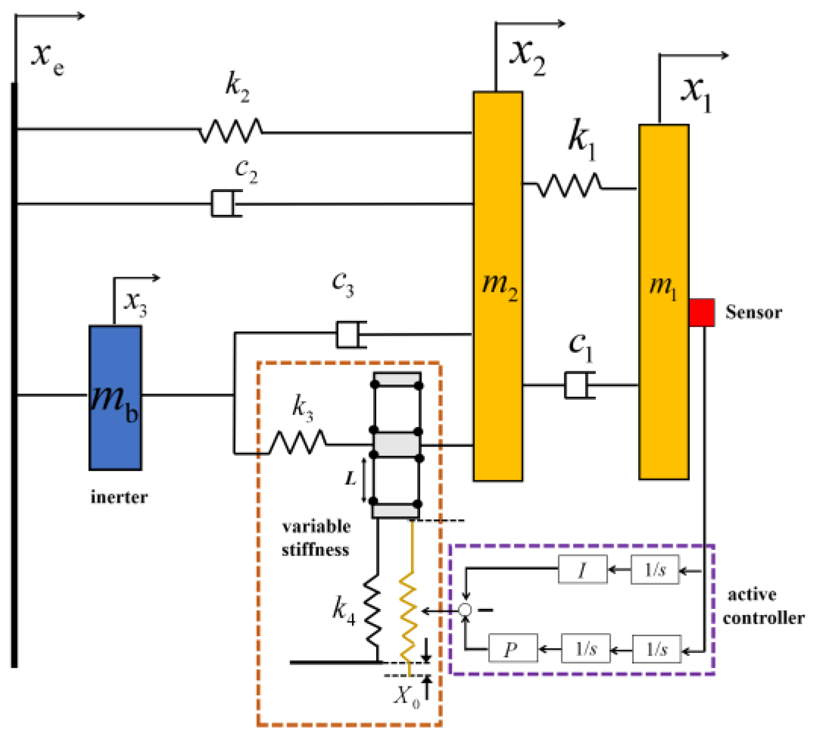
2. Modeling
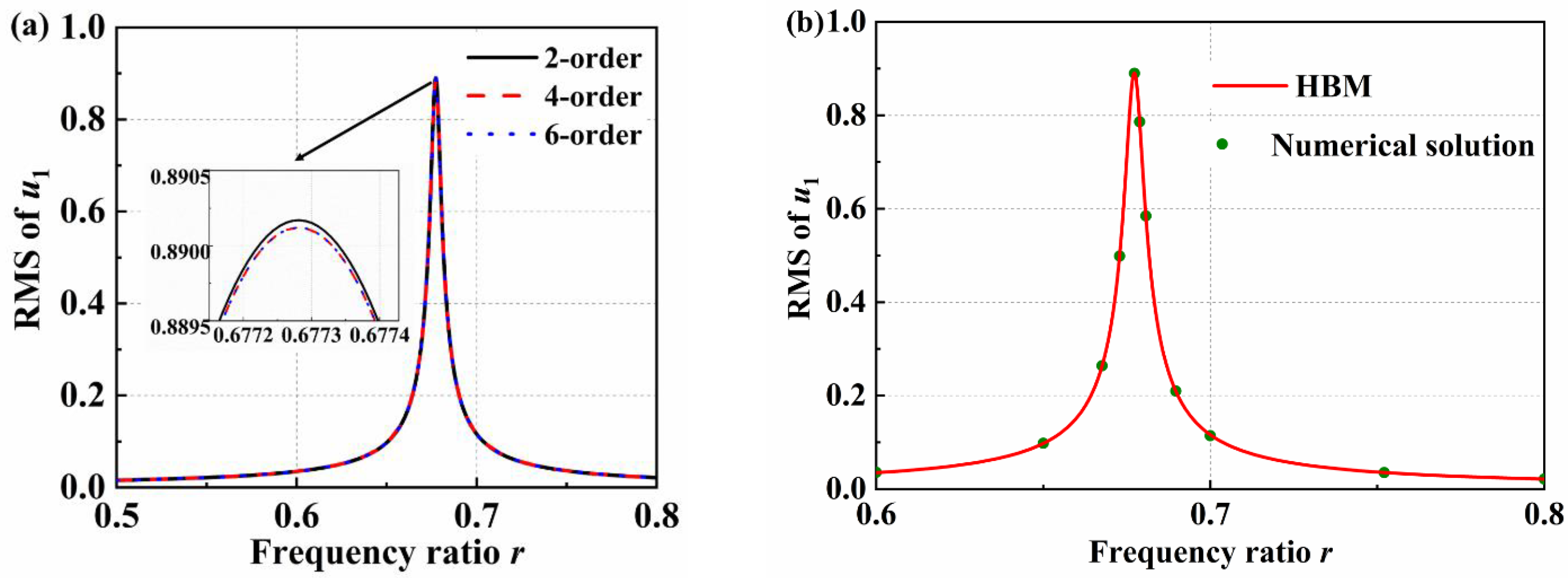
3. Method
4. Results and Discussion
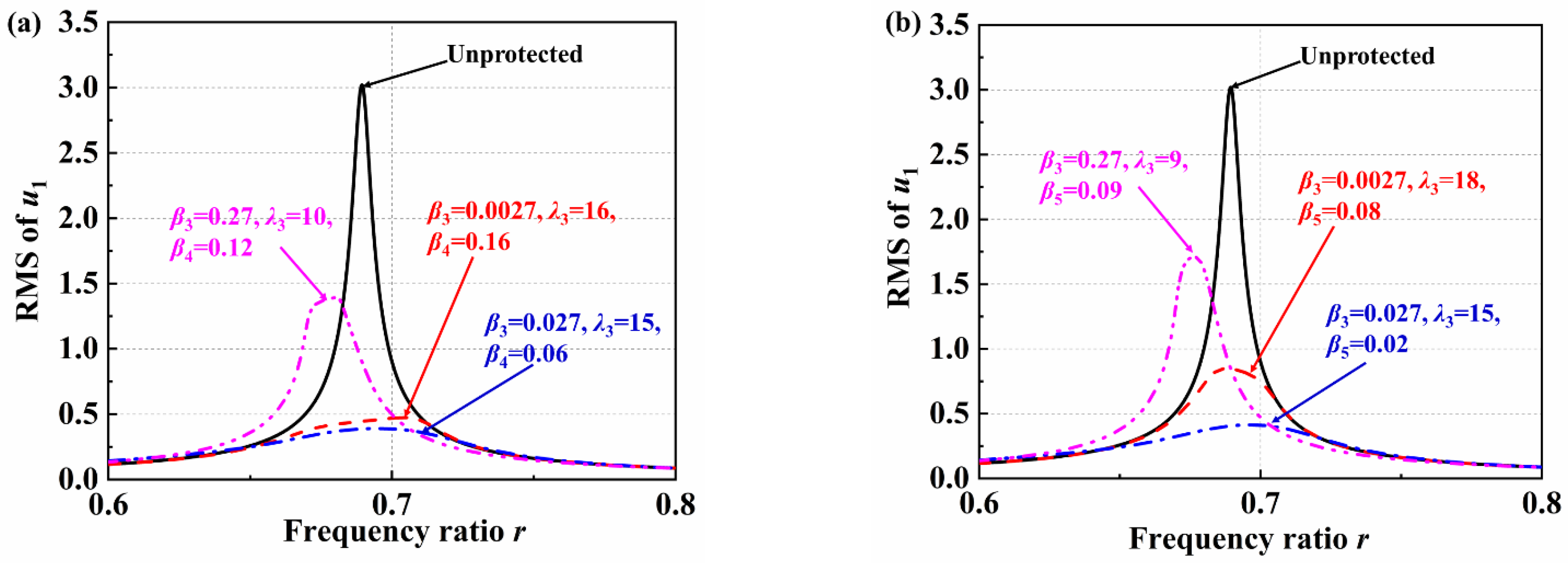
4.1. Vibration Reduction Performance
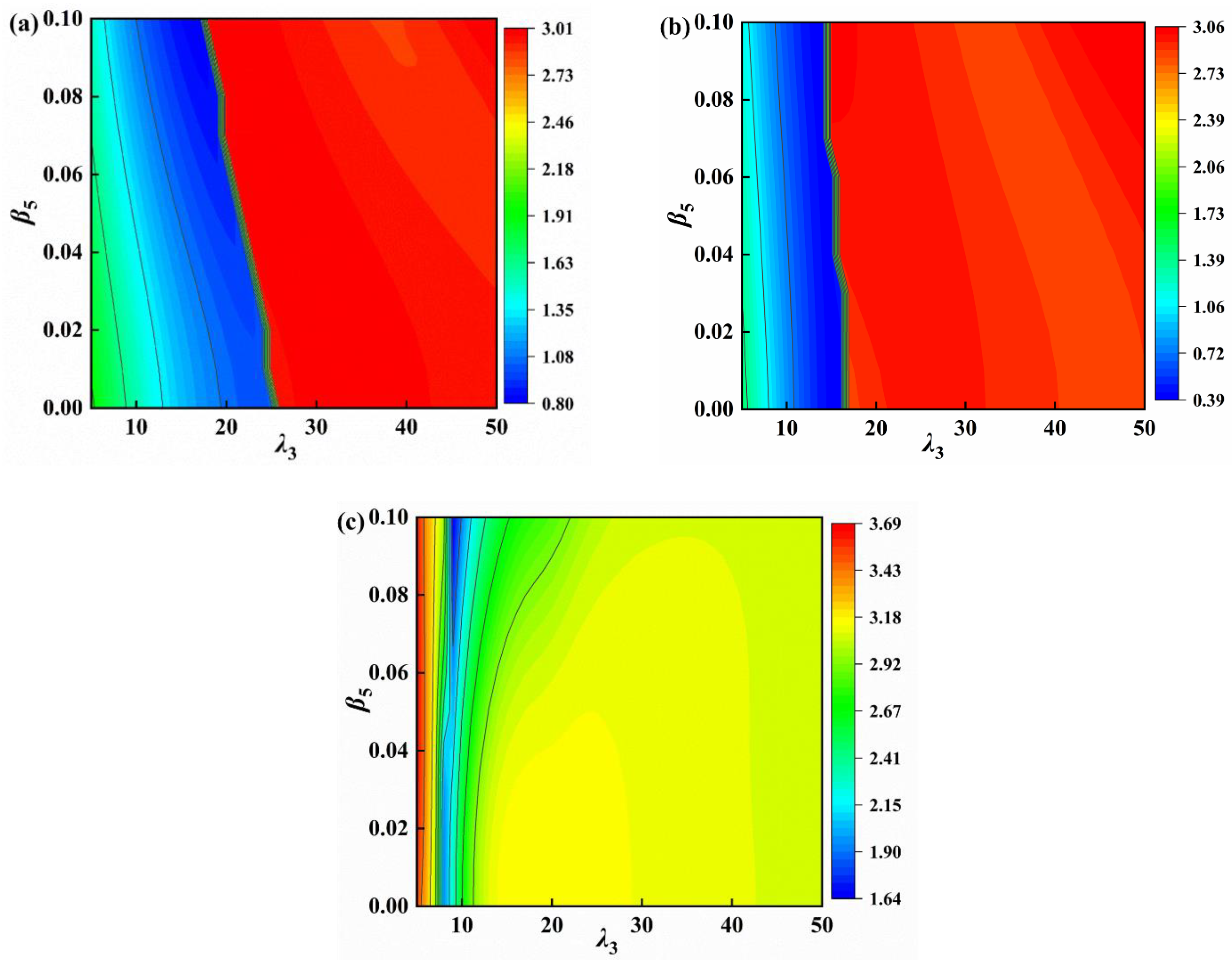
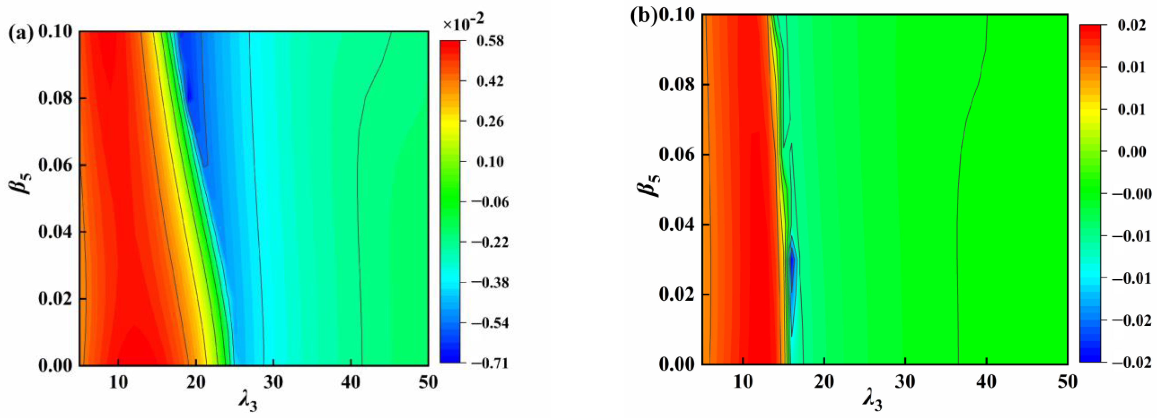
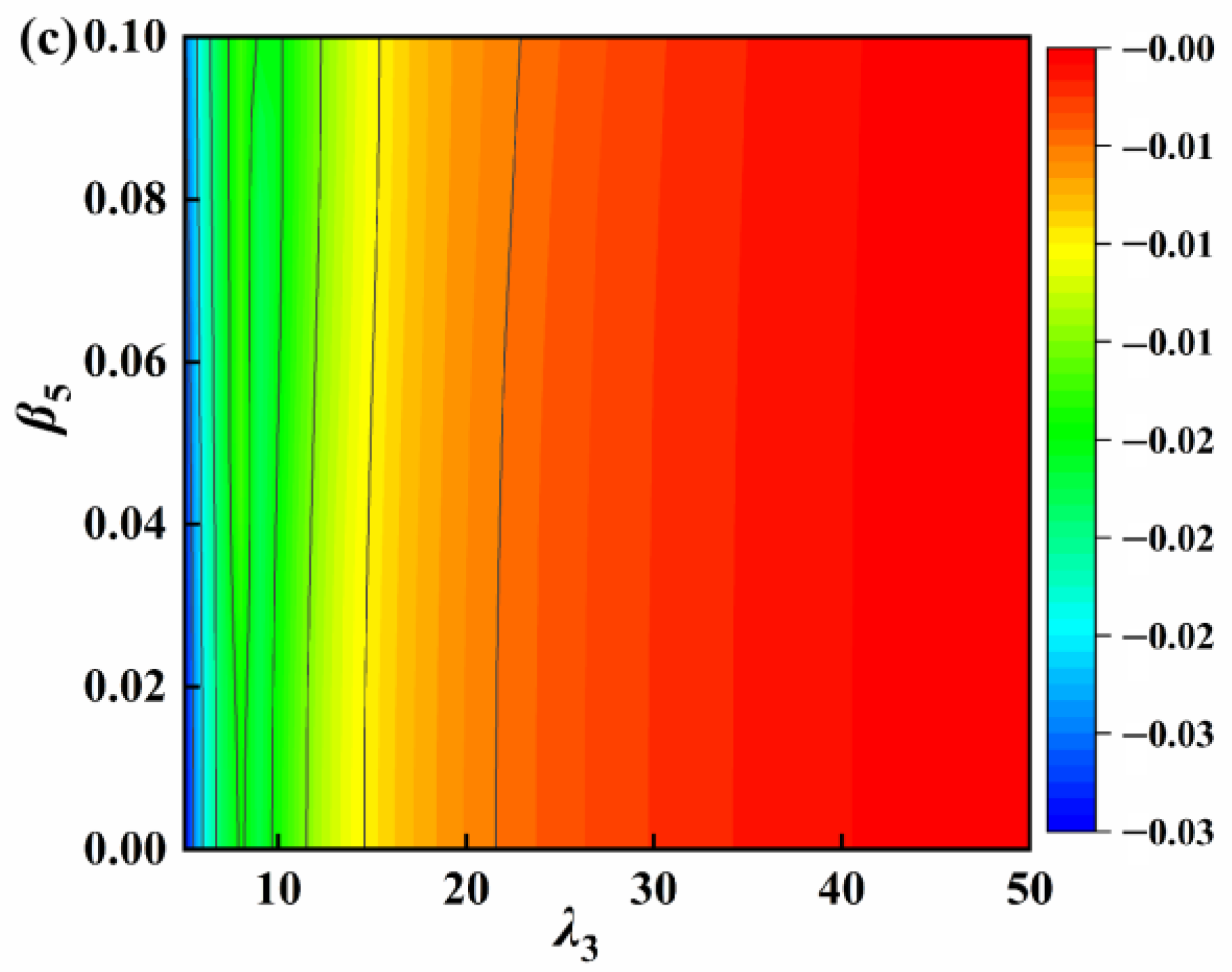
4.2. Parameter Analysis
4.3. Parameter Optimization
4.4. Impulse Response
5. Conclusions
- (1)
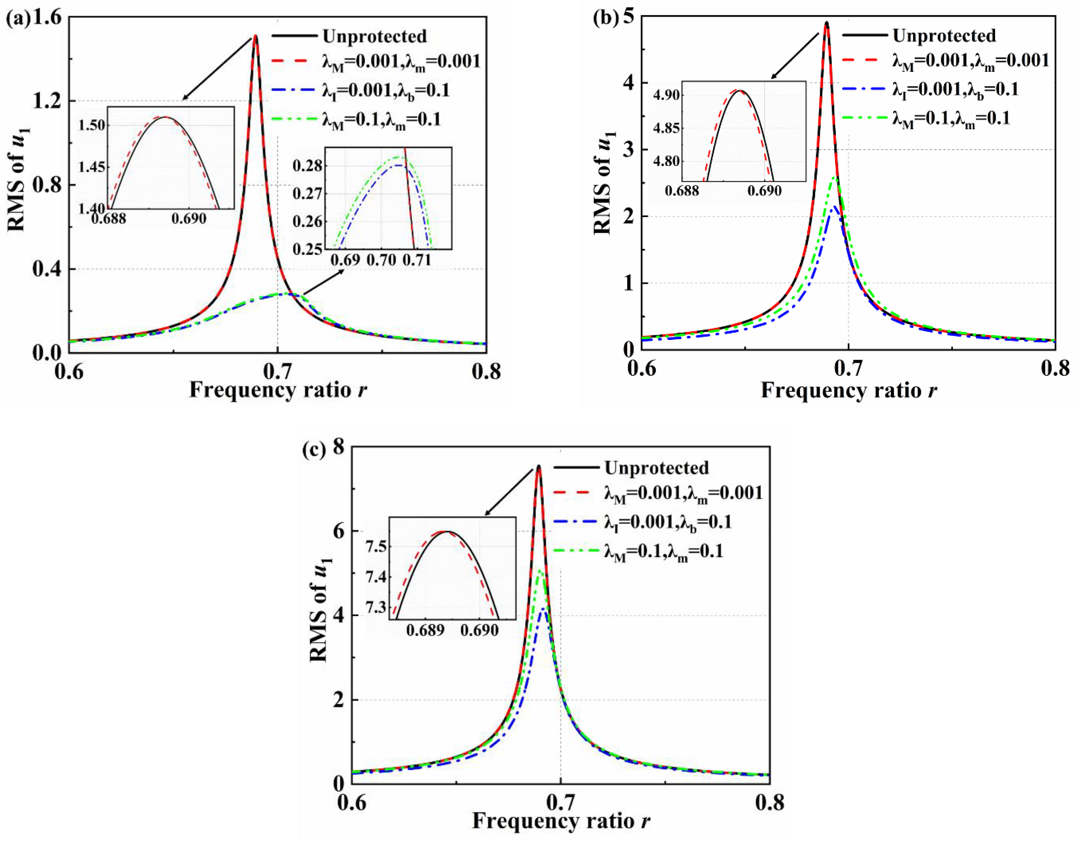
- The performance of the vibration reduction of the VS-TMD-I is much better than the traditional VS-TMD with the same mass ratio. The VS-TMD-I and the traditional VS-TMD have almost the same vibration reduction performance with the same inertance ratio under a small external excitation. The enhancement performance is more obvious with the increase of external excitations. Moreover, the VS-TMD-I has less added mass. The natural frequency of the primary structure is only slightly changed by the VS-TMD-I.
- (2)
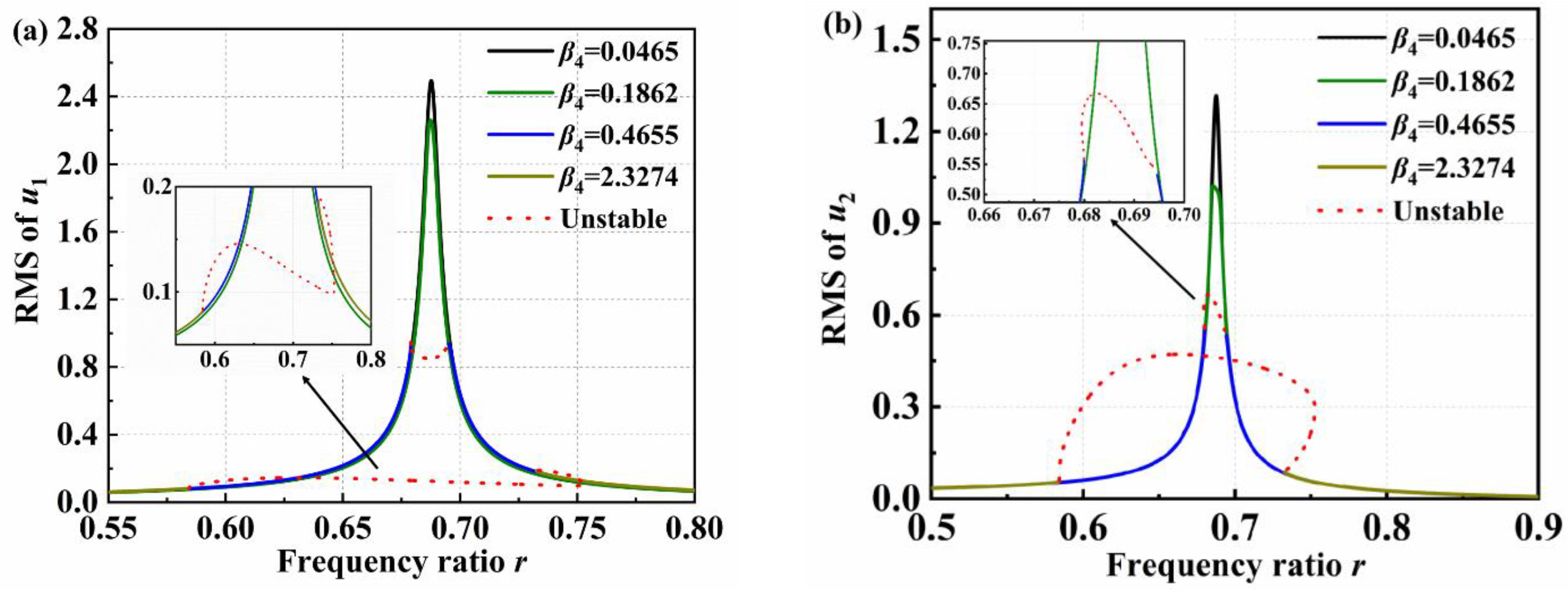
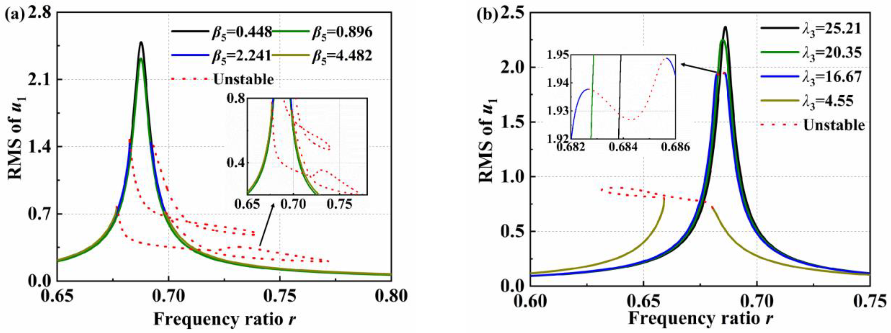
- The primary structure exhibits variable nonlinear dynamic phenomena and unstable response, and the range of unstable band widens as the negative stiffness ratios increase and inertia ratios decrease. Fortunately, the amplitude of the primary structure becomes lower.
- (3)
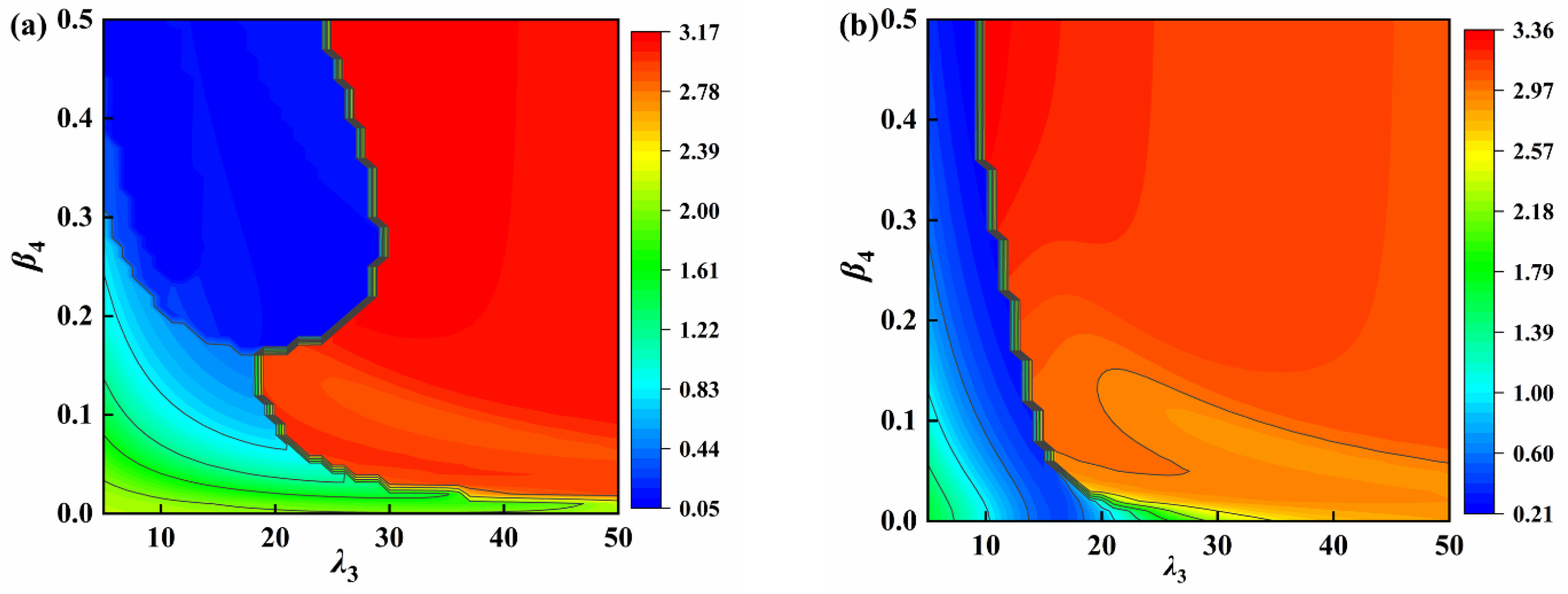
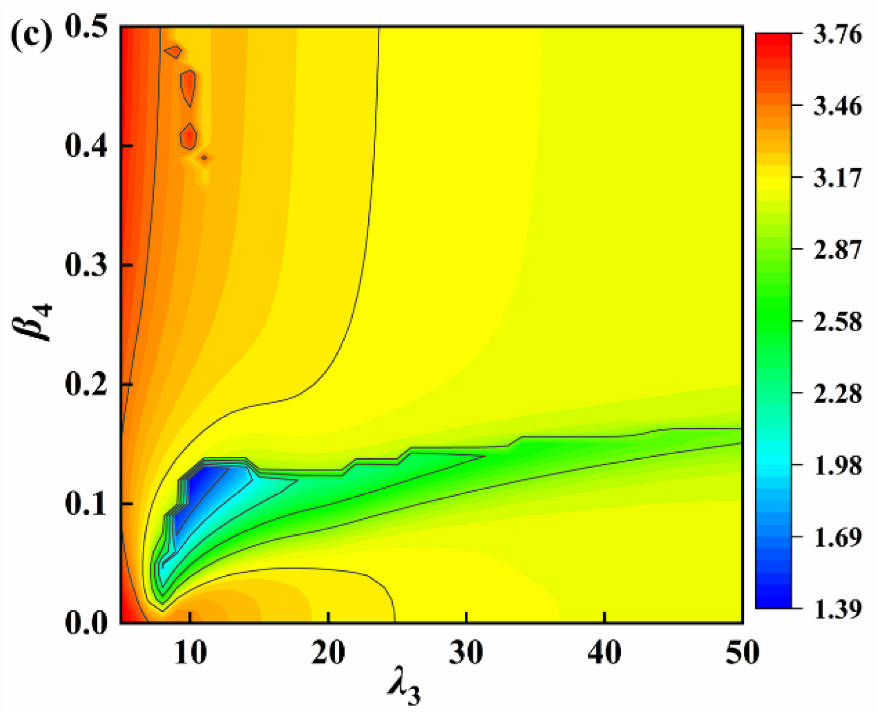
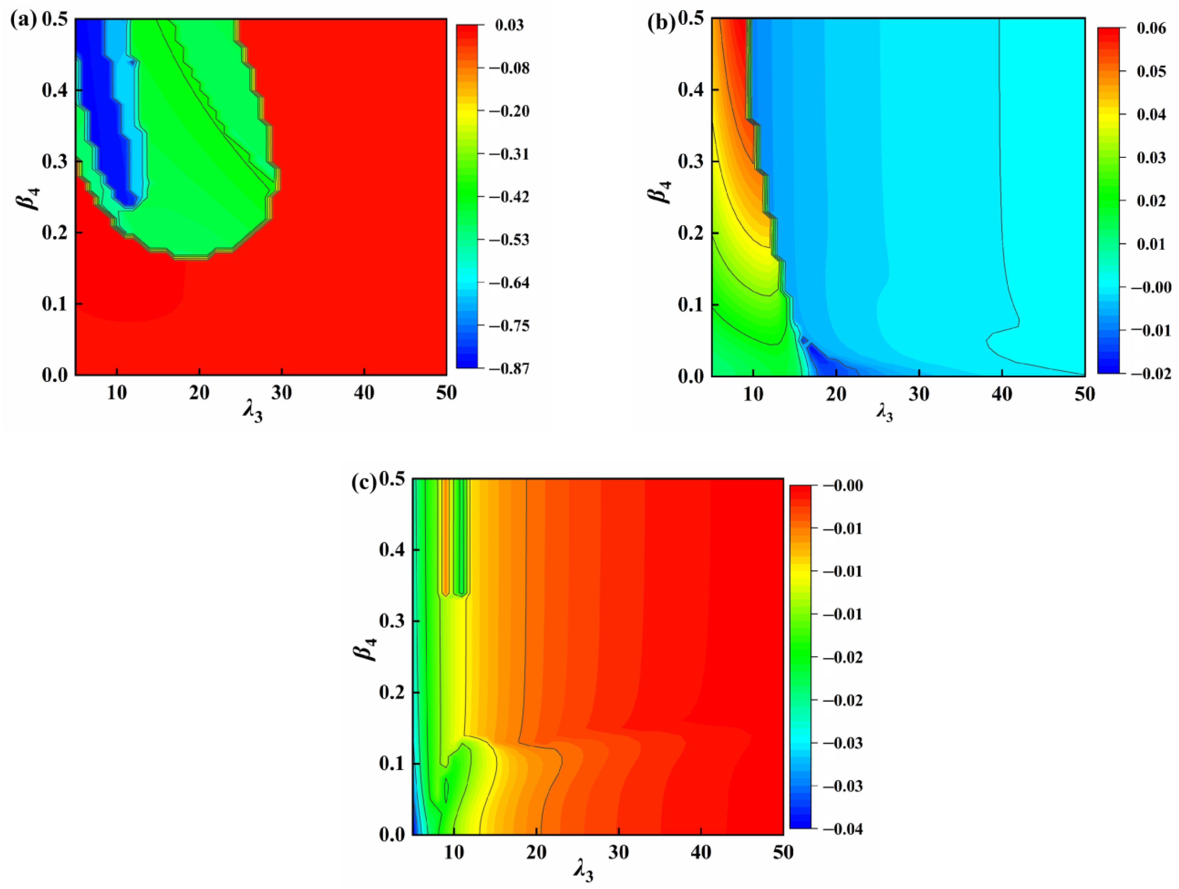
- A frequency change indicator is used as a constraint for the optimal parameter analysis. When the positive stiffness ratio is constant, the optimum negative stiffness ratio and inertance ratio of the VS-TMD-I are searched. The vibration reduction rate can reach 87.09% with the optimal parameters of the VS-TMD-I β3 = 0.027, β4 = 0.06, and λ3 = 15.
- (4)
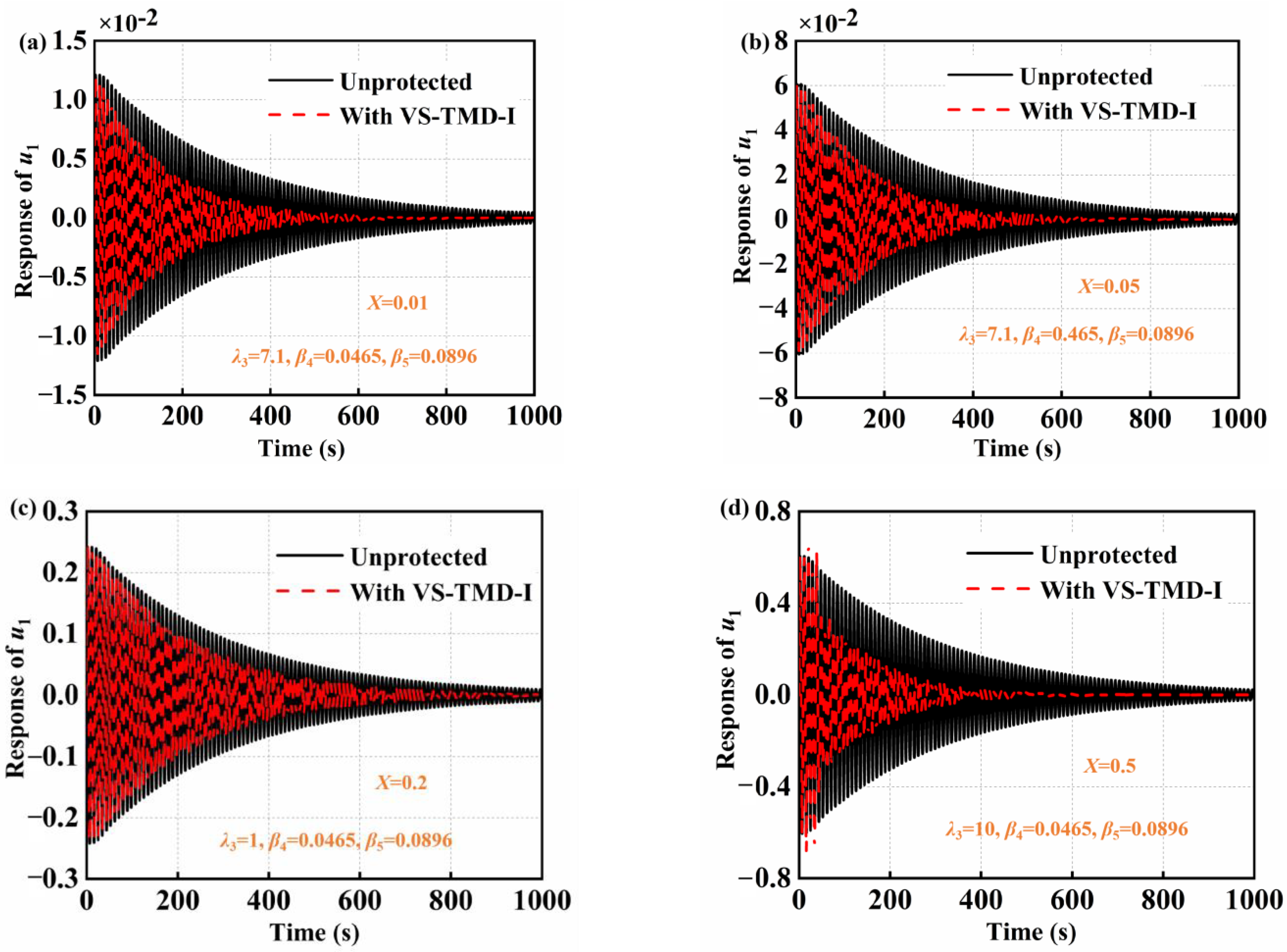
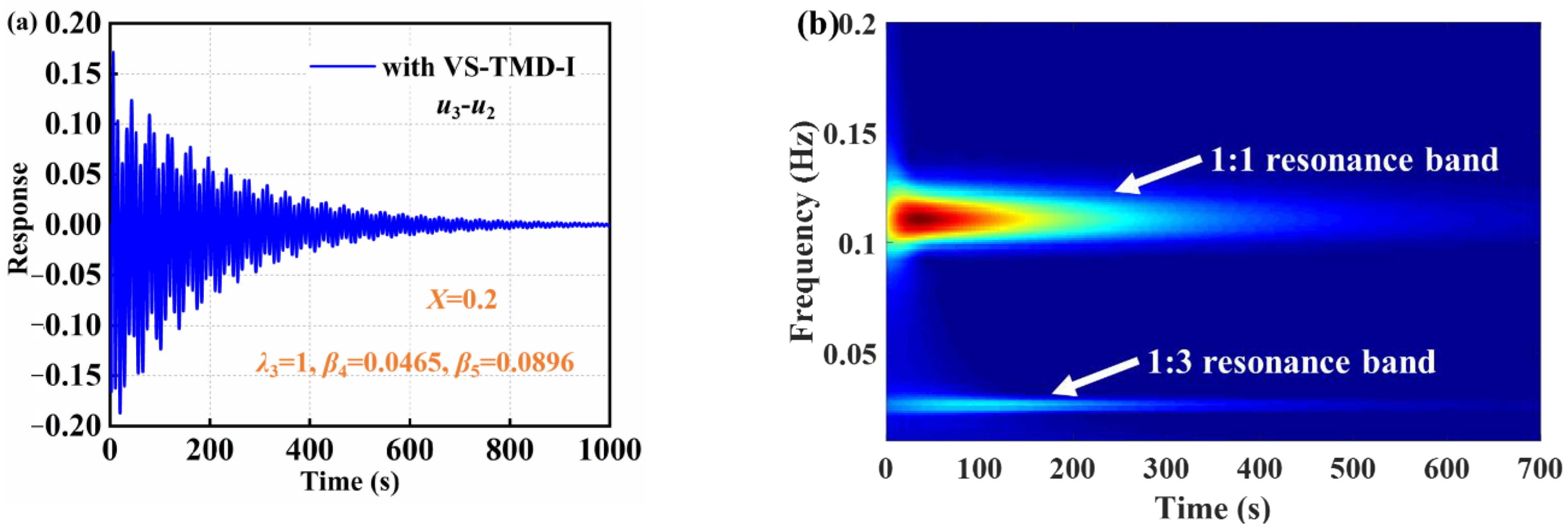
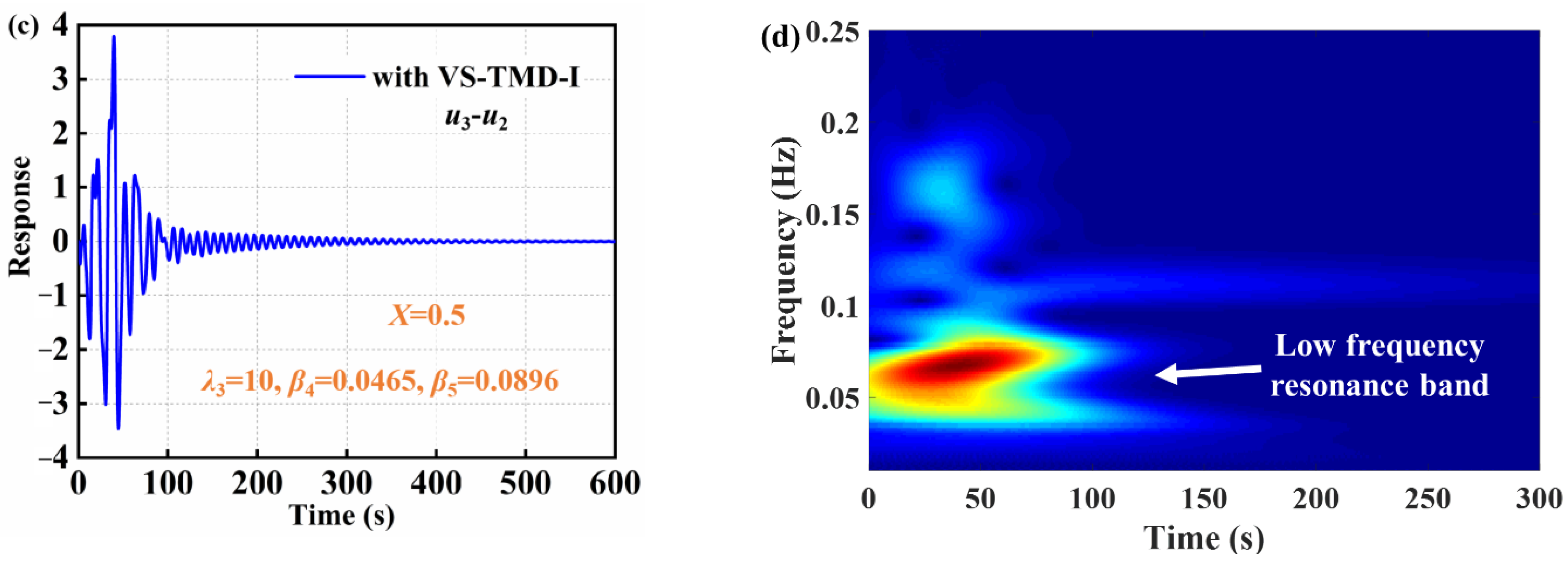
- The VS-TMD-I can improve the energy absorption rate of the primary structure under different initial impulse values. The VS-TMD-I can reduce the time for the primary structure to reach steady state. The primary structure and the new vibration absorber engage in 1:1 internal resonance, 1:2 internal resonance, 1:3 internal resonance, and low-frequency resonance with different initial impulse values based on the wavelet transform spectra.
Author Contributions
Funding
Institutional Review Board Statement
Informed Consent Statement
Data Availability Statement
Conflicts of Interest
References
- Su, X.; Kang, H.; Guo, T. Modelling and energy transfer in the coupled nonlinear response of a 1:1 internally resonant cable system with a tuned mass damper. Mech. Syst. Signal Process. 2021, 162, 108058. [Google Scholar] [CrossRef]
- Yang, F.; Sedaghati, R.; Esmailzadeh, E. Vibration suppression of structures using tuned mass damper technology: A state-of-the-art review. J. Vib. Control. 2021, 28, 812–836. [Google Scholar] [CrossRef]
- Náprstek, J.; Fischer, C. Stable and unstable solutions in auto-parametric resonance zone of a non-holonomic system. Nonlinear Dyn. 2020, 99, 299–312. [Google Scholar] [CrossRef]
- Concha, A.; Thenozhi, S.; Betancourt, R.J.; Gadi, S. A tuning algorithm for a sliding mode controller of buildings with ATMD. Mech. Syst. Signal Process. 2021, 154, 107539. [Google Scholar] [CrossRef]
- Zhang, L.; Xue, S.; Zhang, R.; Xie, L.; Hao, L. Simplified multimode control of seismic response of high-rise chimneys using distributed tuned mass inerter systems (TMIS). Eng. Struct. 2020, 228, 111550. [Google Scholar] [CrossRef]
- Tehrania, G.G.; Dardel, M. Vibration mitigation of a flexible bladed rotor dynamic system with passive dynamic absorbers. Commun. Nonlinear Sci. Numer. Simul. 2019, 69, 1–30. [Google Scholar] [CrossRef]
- Kamgar, R.; Samea, P.; Khatibinia, M. Optimizing parameters of tuned mass damper subjected to critical earthquake. Struct. Des. Tall Spéc. Build. 2018, 27, e1460. [Google Scholar] [CrossRef]
- Kamgar, R.; Gholami, F.; Sanayei, H.R.Z.; Heidarzadeh, H. Modified Tuned Liquid Dampers for Seismic Protection of Buildings Considering Soil–Structure Interaction Effects. Iran. J. Sci. Technol. Trans. Civ. Eng. 2019, 44, 339–354. [Google Scholar] [CrossRef]
- Khatibinia, M.; Gholami, H.; Kamgar, R. Optimal design of tuned mass dampers subjected to continuous stationary critical excitation. Int. J. Dyn. Control. 2017, 6, 1094–1104. [Google Scholar] [CrossRef]
- Salimi, M.; Kamgar, R.; Heidarzadeh, H. An evaluation of the advantages of friction TMD over conventional TMD. Innov. Infrastruct. Solut. 2021, 6, 95. [Google Scholar] [CrossRef]
- Dadkhah, M.; Kamgar, R.; Heidarzadeh, H.; Jakubczyk-Gałczyńska, A.; Jankowski, R. Improvement of Performance Level of Steel Moment-Resisting Frames Using Tuned Mass Damper System. Appl. Sci. 2020, 10, 3403. [Google Scholar] [CrossRef]
- Kleingesinds, S.; Lavan, O. Gradient-based multi-hazard optimization of MTMDs for tall buildings. Comput. Struct. 2021, 249, 106503. [Google Scholar] [CrossRef]
- Qiu, Y.; Jiang, S. Suppression of low-frequency vibration for rotor-bearing system of flywheel energy storage system. Mech. Syst. Signal Process. 2019, 121, 496–508. [Google Scholar] [CrossRef]
- Yin, X.; Song, G.; Liu, Y. Vibration Suppression of Wind/Traffic/Bridge Coupled System Using Multiple Pounding Tuned Mass Dampers (MPTMD). Sensors 2019, 19, 1133. [Google Scholar] [CrossRef] [PubMed] [Green Version]
- Ma, R.; Bi, K.; Hao, H. A novel rotational inertia damper for amplifying fluid resistance: Experiment and mechanical model. Mech. Syst. Signal Process. 2021, 149, 107313. [Google Scholar] [CrossRef]
- Bian, J.; Jing, X. A nonlinear X-shaped structure based tuned mass damper with multi-variable optimization (X-absorber). Commun. Nonlinear Sci. Numer. Simul. 2021, 99, 105829. [Google Scholar] [CrossRef]
- Yan, B.; Yu, N.; Ma, H.; Wu, C. A theory for bistable vibration isolators. Mech. Syst. Signal Process. 2022, 167, 108507. [Google Scholar] [CrossRef]
- Ma, H.; Yan, B. Nonlinear damping and mass effects of electromagnetic shunt damping for enhanced nonlinear vibration isolation. Mech. Syst. Signal Process. 2021, 146, 107010. [Google Scholar] [CrossRef]
- Wang, M.; Sun, F.-F.; Yang, J.-Q.; Nagarajaiah, S. Seismic protection of SDOF systems with a negative stiffness amplifying damper. Eng. Struct. 2019, 190, 128–141. [Google Scholar] [CrossRef]
- Huang, D.; Li, R.; Yang, G. On the dynamic response regimes of a viscoelastic isolation system integrated with a nonlinear energy sink. Commun. Nonlinear Sci. Numer. Simul. 2019, 79, 104916. [Google Scholar] [CrossRef]
- Dekemele, K.; Habib, G.; Loccufier, M. The periodically extended stiffness nonlinear energy sink. Mech. Syst. Signal Process. 2022, 169, 108706. [Google Scholar] [CrossRef]
- Wang, Q.; Dong, X.; Li, L.; Yang, Q.; Ou, J. Wind-induced vibration control of a constructing bridge tower with MRE variable stiffness tuned mass damper. Smart Mater. Struct. 2020, 29, 045034. [Google Scholar] [CrossRef]
- Schleiter, S.; Altay, O. Identification and semi-active control of structures with abrupt stiffness degradations. Mech. Syst. Signal Process. 2021, 163, 108131. [Google Scholar] [CrossRef]
- Wang, F.; Sun, X.; Meng, H.; Xu, J. Time-Delayed Feedback Control Design and Its Application for Vibration Absorption. IEEE Trans. Ind. Electron. 2020, 68, 8593–8602. [Google Scholar] [CrossRef]
- Leng, D.; Yang, Y.; Xu, K.; Li, Y.; Liu, G.; Tian, X.; Xie, Y. Vibration control of offshore wind turbine under multiple hazards using single variable-stiffness tuned mass damper. Ocean Eng. 2021, 236, 109473. [Google Scholar] [CrossRef]
- Sun, C.; Nagarajaiah, S. Study of a novel adaptive passive stiffness device and its application for seismic protection. J. Sound Vib. 2019, 443, 559–575. [Google Scholar] [CrossRef]
- Churchill, C.B.; Shahan, D.W.; Smith, S.P.; Keefe, A.C.; McKnight, G.P. Dynamically variable negative stiffness structures. Sci. Adv. 2016, 2, e1500778. [Google Scholar] [CrossRef] [Green Version]
- Xu, K.; Zhang, Y.; Zhu, Y.; Zang, J.; Chen, L. Dynamics Analysis of Active Variable Stiffness Vibration Isolator for Whole-Spacecraft Systems Based on Nonlinear Output Frequency Response Functions. Acta Mech. Solida Sin. 2018, 33, 731–743. [Google Scholar] [CrossRef]
- Zhang, Y.; Li, Z.; Xu, K.; Zang, J. A lattice sandwich structure with the active variable stiffness device under aerodynamical condition. Aerosp. Sci. Technol. 2021, 116, 106849. [Google Scholar] [CrossRef]
- Smith, M. Synthesis of mechanical networks: The inerter. IEEE Trans. Autom. Control 2002, 47, 1648–1662. [Google Scholar] [CrossRef]
- Chen, M.Z.; Papageorgiou, C.; Scheibe, F.; Wang, F.-C.; Smith, M.C. The missing mechanical circuit element. IEEE Circuits Syst. Mag. 2009, 9, 10–26. [Google Scholar] [CrossRef]
- Baduidana, M.; Kenfack-Jiotsa, A. Optimum design for a novel inerter-based vibration absorber with an amplified inertance and grounded stiffness for enhanced vibration control. J. Vib. Control. 2021, 28, 2502–2518. [Google Scholar] [CrossRef]
- Pan, C.; Zhang, R.; Luo, H.; Li, C.; Shen, H. Demand-based optimal design of oscillator with parallel-layout viscous inerter damper. Struct. Control. Health Monit. 2017, 25, e2051. [Google Scholar] [CrossRef]
- Alotta, G.; Failla, G. Improved inerter-based vibration absorbers. Int. J. Mech. Sci. 2021, 192, 106087. [Google Scholar] [CrossRef]
- Zhang, Z.; Zhang, Y.-W.; Ding, H. Vibration control combining nonlinear isolation and nonlinear absorption. Nonlinear Dyn. 2020, 100, 2121–2139. [Google Scholar] [CrossRef]
- Brzeski, P.; Perlikowski, P. Effects of play and inerter nonlinearities on the performance of tuned mass damper. Nonlinear Dyn. 2017, 88, 1027–1041. [Google Scholar] [CrossRef] [Green Version]
- Yang, J.; Jiang, J.Z.; Neild, S.A. Dynamic analysis and performance evaluation of nonlinear inerter-based vibration isolators. Nonlinear Dyn. 2020, 99, 1823–1839. [Google Scholar] [CrossRef] [Green Version]
- Zhang, R.; Zhao, Z.; Dai, K. Seismic response mitigation of a wind turbine tower using a tuned parallel inerter mass system. Eng. Struct. 2019, 180, 29–39. [Google Scholar] [CrossRef]
- Gonzalez-Buelga, A.; Lazar, I.F.; Jiang, J.Z.; Neild, S.A.; Inman, D.J. Assessing the effect of nonlinearities on the performance of a tuned inerter damper. Struct. Control. Health Monit. 2016, 24, e1879. [Google Scholar] [CrossRef] [Green Version]
- Barredo, E.; Rojas, G.L.; Mayén, J.; Flores-Hernández, A. Innovative negative-stiffness inerter-based mechanical networks. Int. J. Mech. Sci. 2021, 205, 106597. [Google Scholar] [CrossRef]
- Zhang, Z.; Lu, Z.-Q.; Ding, H.; Chen, L.-Q. An inertial nonlinear energy sink. J. Sound Vib. 2019, 450, 199–213. [Google Scholar] [CrossRef]
- Xu, K.-F.; Zhang, Y.-W.; Zang, J.; Niu, M.-Q.; Chen, L.-Q. Integration of vibration control and energy harvesting for whole-spacecraft: Experiments and theory. Mech. Syst. Signal Process. 2021, 161, 107956. [Google Scholar] [CrossRef]


| Parameters | Values | Parameters | Values |
|---|---|---|---|
| 1.92 | 0.279 | ||
| 1.1528 | 0.054 | ||
| 0.0312 | 0.0104 | ||
| 0.016 | 10 | ||
| 0.00208 | 0.01079 | ||
| 106.842 | 0.1928 |
| Excitation Amplitudes | Parameters | Values | ||
|---|---|---|---|---|
| VS-TMD | VS-TMD-I | VS-TMD | ||
| Mass ratio | λM = 0.001 | λI = 0.001 | λM = 0.1 | |
| Inertance ratio | λm = 0.001 | λb = 0.1 | λm = 0.1 | |
| fe = 0.2 mm | RMS of u1 | 1.51 | 0.28 | 0.283 |
| Decreased (%) | −0.7 | 81.33 | 81.13 | |
| fe = 0.65 mm | RMS of u1 | 4.91 | 2.15 | 2.58 |
| Decreased (%) | −0.2 | 56.22 | 47.34 | |
| fe = 1 mm | RMS of u1 | 7.55 | 4.15 | 5.07 |
| Decreased (%) | −0.7 | 44.67 | 32.4 | |
Disclaimer/Publisher’s Note: The statements, opinions and data contained in all publications are solely those of the individual author(s) and contributor(s) and not of MDPI and/or the editor(s). MDPI and/or the editor(s) disclaim responsibility for any injury to people or property resulting from any ideas, methods, instructions or products referred to in the content. |
© 2023 by the authors. Licensee MDPI, Basel, Switzerland. This article is an open access article distributed under the terms and conditions of the Creative Commons Attribution (CC BY) license (https://creativecommons.org/licenses/by/4.0/).
Share and Cite
Xu, K.-F.; Zhang, Y.-W.; Niu, M.-Q.; Chen, L.-Q. Dynamics Analysis of a Variable Stiffness Tuned Mass Damper Enhanced by an Inerter. Appl. Sci. 2023, 13, 1404. https://doi.org/10.3390/app13031404
Xu K-F, Zhang Y-W, Niu M-Q, Chen L-Q. Dynamics Analysis of a Variable Stiffness Tuned Mass Damper Enhanced by an Inerter. Applied Sciences. 2023; 13(3):1404. https://doi.org/10.3390/app13031404
Chicago/Turabian StyleXu, Ke-Fan, Ye-Wei Zhang, Mu-Qing Niu, and Li-Qun Chen. 2023. "Dynamics Analysis of a Variable Stiffness Tuned Mass Damper Enhanced by an Inerter" Applied Sciences 13, no. 3: 1404. https://doi.org/10.3390/app13031404