Article

Recognizing and Recovering Ball Motion Based on Low-Frame-Rate Monocular Camera

Software College, Northeastern University, Shenyang 110169, China
*
Authors to whom correspondence should be addressed.
Appl. Sci. 2023, 13(3), 1513; https://doi.org/10.3390/app13031513
Submission received: 24 December 2022 / Revised: 12 January 2023 / Accepted: 17 January 2023 / Published: 23 January 2023

Abstract

:
Reconstructing sphere motion is an essential part of indoor screen-based ball sports. Current sphere recognition techniques require expensive high-precision equipment and complex field deployment, which limits the application of these techniques. This paper proposes a novel method for recognizing and recovering sphere motion based on a low-frame-rate monocular camera. The method captures ball motion streaks in input images, reconstructs trajectories in space, and then estimates ball speed. We evaluated the effectiveness of the streak detection method and obtained an F1-score of 0.97. We also compared the performance of the proposed trajectory reconstruction method with existing methods, and the proposed method outperformed the compared techniques.

1. Introduction

Sphere motion reconstruction techniques based on images are widely used in indoor screen-based ball sports such as indoor golf, baseball, soccer, as well as other interdisciplinary application areas including geological engineering [1] and cell biology [2]. Sphere motion reconstruction consists of two basic steps: (1) projection extraction and (2) trajectory reconstruction. The result of projection extraction is a set of pixels, and the accuracy of these pixels significantly impacts space position mapping results in trajectory reconstruction. Therefore, sphere motion reconstruction usually requires expensive high-precision equipment and complex on-site deployment to capture precise sphere projections. The high-cost equipment thus limits the application of sphere motion reconstruction.
Researchers have proposed sphere motion reconstruction methods based on low frame rate cameras to reduce hardware costs. When using a still camera to capture a moving sphere, the sphere leaves a visible but blurred streak on the image plane due to its high speed relative to the exposure time. These streaks are referred to as motion blurs. Researchers have proposed a series of methods to extract these blurs and deduce motion trajectories based on them.
These methods usually extract streaks based on the shapes of streaks when the projections are circle-like, i.e., the difference between the edge pixels of foreground and background in an image is obvious. In this scenario, a standard method is fitting streaks using circles and ellipses. In [3,4,5,6], by calculating the gradient of images, Huajie Wen et al. obtained circle edges directly, thus significantly reducing the difficulty of subsequent analysis of sphere position. In [7], Jung et al. used half circle fitting that considers light direction to extract center points of flying golf balls on images. In [8], ellipses are used to fit a moving sphere and its shadow to triangulate the ball position. In [9], Wen et al. used the YOLOv3-Tiny deep learning algorithm to capture and detect the pitched baseball. These methods prove that using circle and ellipse fitting to find sphere projection is effective. However, when the ball speed is too fast relative to exposure time, its streak edge will blend into the background, forming a highly blurred streak. In this case, the foreground and background edge pixels will be challenging to detect for circle fitting. Therefore, these methods are not effective when using low frame rate cameras.
Researchers have devised a series of methods to deal with highly blurred streaks. One approach is to remove blur artifacts. For example, in [10], Lin et al. used the Wiener filter to obtain a sequence of deblurred images to pick the most circle-like objects. However, this method is sensitive to streak length. Another approach is to exploit the blur. In [11,12], Boracchi et al. and Caglioti et al. proposed models based on pixel intensities to obtain the contours of projections. However, the model in [11] also had the limitation of being sensitive to streak length. Meanwhile, the model in [12] lacked the optimization of output points and thus magnified the error in semi-ellipse fitting. In [13], Sh. Rezvankhah et al. used the Fourier transform to determine the motion state of a fast moving puck. However, due to the inability to detect depth information, this method is only applicable to two-dimensional tabletop ball games.
After processing the blurred images and obtaining the streaks, researchers need to infer the ball motion state. Some combined a sequence of frames or used multiple synchronized cameras to analyze ball movements. For example, in [14], the ball motion trajectories were determined based on position variation in frame sequences. However, this method required that different frames had captured the motion processes and that at least a few were valid. In [7], several multiple-exposure pictures from multiple synchronized cameras were used to determine sphere position. However, deploying the stroboscope of synchronized cameras undoubtedly increased costs.
In summary, using low frame rate cameras can bring challenges to existing sphere motion recognition methods: (1) The streak can be intermittent, which is a rarely considered situation in existing methods. (2) The streak edges are blurred, leading to failures in extracting point pairs from contours.
This paper presents a solution to reconstruct sphere motion from one single frame captured by a monocular low frame rate camera. To address the first problem mentioned above, we propose a method that combines an improved interframe difference algorithm and some filters to identify streaks. Our improved frame difference method can reduce noise in the output result. Furthermore, a series of filters based on the streak’s size, ratio, pixel intensity, and boundary are used to select candidate blocks. We then concatenate these candidate blocks together to form a target streak. To address the second problem mentioned above, we propose a new point pair matching method based on streak axis iteration. The method obtains the approximate axis of the streak from the contour and then updates the axis with the gray scale information of the streak. Based on the optimized streak axis, the method outputs accurate coupled point pair sequences. We evaluate the proposed methods in a series of experiments. The F1-score of distinguishing streaks is 0.97, and the error in the calculation of sphere motion is less than the methods in [11,12]. These results prove that the proposed methods are effective.

2. Related Work

2.1. Projection Extraction

Projection extraction extracts images of motion trajectories from photographs. A photograph contains three parts: (1) ball streak, (2) background, and (3) noises. Among them, ball streaks and noises constitute the foreground. In other words, projection extraction eliminates background and noises and leaves the ball streak alone.
In the methods proposed in [3,4], the foreground and background were distinguished based on the P-tile and Otsu algorithms to obtain gray scale thresholds. However, P-tile and Otsu rely on Region of Interest (RIO) to reduce the detection range, forcing these algorithms to exploit multiple frames.
To extract ball streaks from foregrounds, a projection extraction method needs to filter noises, including underexposure noises, variations of ambient light, and human body movements. In [3], Wen et al. processed mages with the Gaussian filter, which removed underexposure noises and light variations. However, the Gaussian filter can displace several pixels towards the center of the streak in the smoothing phase, and thus the ball radius in that image will be smaller than its actual value. In [4], Wang et al. used P-tile to address the underexposure noise issue and filtered ball projections from noises based on the contour shape characteristics. In the method proposed in [7,14], Ren et al. and Jung et al. filtered ball candidates using sizes, width–height ratios of circumscribed rectangles, and color features. These methods focused on the external characteristic of streaks and worked well in uncomplicated environments. However, these methods fail to extract ball streaks when noises and projections have similar shapes and colors.
To obtain precise contours in blur images, in [11] Boracchi et al. extracted two sets of contour points using the pixel intensity values along the streak directions. Each set of points circled the ball image by conic fitting. However, such an approach only works well when the streak is short. Then, in [12] to deal with longer streaks, the authors proposed using semiellipses to fit the pixel intensities along the streak profile to obtain precise lateral contours. However, this method requires an extra further candidate point matching process, which is unstable when fitting errors cannot be ignored.

2.2. Trajectory Reconstruction

The information of a ball trajectory contains ball position, movement direction, and velocity. After obtaining the projection of a ball, a trajectory can be reconstructed with camera imaging principles. In the method proposed in [10], Lin et al. used deblurred circles to recover sphere positions in space and determined speeds by sphere movement distances between two adjacent frames. In the method proposed by [8], Zhang et al. estimated ball positions using a simple triangulation and predicted follow-up positions of moving balls using the Kalman filter. These methods work well when projections are circle-like but fail in other cases. On the other hand, these methods cost more time since the information on directions and velocities is based on the analysis of multiple frames.
To deal with non-circle-like projections, researchers have devised models based on the pixel intensity of streaks. Streaks in long-exposure photographs of a moving sphere contain more information than circle-like projections. In this case, only one image frame may be enough to reconstruct a trajectory. A motion-blurred streak is the image of a canal surface. In [15], Caglioti et al. operated on properties of canal surface contours. They reconstructed a canal surface with an ordered sequence of coupled point pairs. Then in [12], they proposed a model to obtain speed information with the pixel intensity of streaks. However, due to the change of ambient light and non-uniform background in long-exposure photographs, streaks can easily become incomplete. In this case, this model fails to build out a complete trajectory.

3. Method

The axis of the ball trajectory in space is a planar curve with a slight curvature, and this trajectory is imaged as an elongated semitransparent streak. The streak can be very vague and intermittent, making it impossible for existing methods to reconstruct sphere motion. In this section, we present our sphere motion reconstruction method in detail. We first introduce a method to extract elongated semitransparent objects. Then, based on the extracted object, we develop a novel model to reconstruct trajectories.

3.1. Overview

A canal surface is obtained as the envelope of a family of spheres of constant radius, whose center is swept along a space curve. Such a curve is called an axis [15]. Each streak corresponds to a unique ball trajectory. Therefore, once exposure time, background, and sphere color are known, the 3D sphere motion trajectory and speed can be uniquely determined. This paper reconstructs sphere motion by analyzing streaks based on the above characteristics.
Our sphere motion reconstruction method consists of three steps: (1) acquiring contours from original images, (2) matching coupled point pairs, and (3) reconstructing trajectories based on the coupled point pairs. Figure 1 shows the overall steps of our proposed method, and Figure 2 is the flow diagram of our sphere motion reconstruction method.
1. Acquiring contours: contours are the boundaries of an image’s streak and background. Each contour is a collection of contour points. When a streak is clear, the Canny algorithm proposed by John Canny or the convolutional network-based tube contour detection method [16] proposed by Cheng et al., can directly derive an accurate sequence of contour points. However, the image of a high-speed moving sphere can be very blurry, and the contour line output by Canny becomes cluttered and incomplete. Moreover, these contours contain a lot of noise caused by light and human motion. Figure 1 contains a black streak as the target streak. Figure 1b shows the contour lines output by Canny, and the streak extracted is incomplete. To address the streak fragmentation problem and the effect of noise, we propose exploiting streak shapes and internal pixel features to extract the complete contours.
2. Matching coupled point pairs: After obtaining contours, a sequence of coupled point pairs can be matched. A canal surface is equivalent to the union of circumferences with a constant radius. Such a circumference is called a cross section, and each cross section is centered on the axis. Two contour points are said to be coupled if they are the image of two points on the same cross section [15]. As an example, in Figure 1b, a coupled point pair is formed by two red points on the lateral contours. This coupled point pair can uniquely determine a ball position in space. A contour point pair obtained using a traditional method (e.g., [15]) has a small fitting error since the profile is not completely perpendicular to the streak direction. The effect of this error will be magnified when reconstructing the corresponding cross section. In practical application scenarios, where high-speed moving spheres are imaged more blurred, the evaluated streak direction will have a more significant error. Therefore, the traditional contour point pairs detection method will fail. To address this problem, this paper proposes an iterative method to update the contour point pairs and thus obtain an accurate sequence of contour point pairs.
3. Reconstructing trajectories: A trajectory is formed by a sequence of ball positions, directions, and velocities. The midpoint of a coupled point pair is not the image of the sphere’s center; thus, the contour point pair cannot be directly mapped to its corresponding sphere in 3D space. Therefore, for each coupled point pair, the image of its corresponding sphere center should be estimated. In this paper, we design a model to estimate the images of sphere centers and map the coupled point pairs to their corresponding sphere locations in space. As shown in Figure 1d, the coupled point pair in red color has been mapped to a ball in space. After mapping all the pairs in the sequences, a sphere motion trajectory composed of the sphere position sequences will be obtained. The sphere motion velocity can be estimated with the trajectory based on pixel intensities.

3.2. Acquiring Contours

Due to nonuniform backgrounds, a streak is often divided into multiple intermittent blocks. Meanwhile, due to ambient light variations and the human body, these streak blocks often coexist with noise blocks. Therefore, it is difficult to distinguish a streak accurately using the interframe difference method alone. To address this problem, this paper proposes a streak block detection method. The method first detects candidate blocks by using a semi-elliptical fitting method to fit the profile of streaks and then concatenates valid blocks in these candidate blocks into a complete streak. By this means, streak blocks can be distinguished in a noisy environment. Before presenting our method, we first introduce the streak profile fitting method.

3.2.1. Fitting Streak Profiles

The edges of the streak of a fast-moving sphere gradually merge with the background, making it difficult to obtain an accurate boundary. The Canny algorithm is a commonly used edge detection algorithm, which could roughly identify the edge of the streaks. However, due to the pixel offset problem in the Canny algorithm, there is an offset in the output contours [12]. On the other hand, contours obtained by Canny may be too tortuous in a local area. Thus, contour points are distorted in these areas. Both phenomena result in inaccurate output streak contours. To obtain accurate contours, researchers have focused on the pixel intensity of the streaks and found that the closer to the center of the streak, the closer the pixel intensity value is to the sphere. Therefore, based on the above feature, they use a profile fitting model to derive the contour points.
The cross section perpendicular to the lateral contour of a streak is called a profile. A pixel point C x y on the profile is a convex linear combination of the ball intensity F x y and the background pixels intensity B x y :
C x y = α F x y + ( 1 α ) B x y
where α is the ratio of the sphere coverage time to the exposure duration at the image point ( x , y ) . Along the profile, with Equation (1), a sequence of α is obtained. Since the α values have a semi-elliptic shape, they can be fitted using nonlinear least-squares minimization. In nonlinear least-squares minimization, the updating parameter list b = [ c , r , t ] T consists of the center c of the semi-ellipse on the horizontal axis, a horizontal axis of radius r, and a vertical axis of radius k. The error R i for each sample i and the cost function ϕ ( b ) are as follows:
R i = ( x i c ) 2 r 2 + y 2 k 2 1
ϕ ( b ) = 1 2 i = 0 m R i ( b ) 2
The right part in Equation (3) is multiplied by 1 2 for ease of derivation. The aim is to obtain b that minimizes ϕ ; thus we calculate Jacobi matrix J R for R and then expect the partial derivative ϕ of ϕ to be 0 :
ϕ = J R ( b ) T R ( b ) w h e r e { J R ( b ) } i j = R i ( b ) b j , J R R m × 3
Due to the nonlinear relationship between R i and b, the Newton method is used to obtain increments b for updating b:
b = J R ( b ) T J R ( b ) 1 J R ( b ) T J R ( b )
Taking Figure 3 for example, the blue curve represents the α values, and the green curve is the fitting result.
Based on the profile fitting model, given a point in the streak and the streak direction, we can deduce two contour points of the streak and the center of these two points. The contour points output by the model have higher confidence than those output by the Canny algorithm since the model has exploited pixel intensity information within the streak.

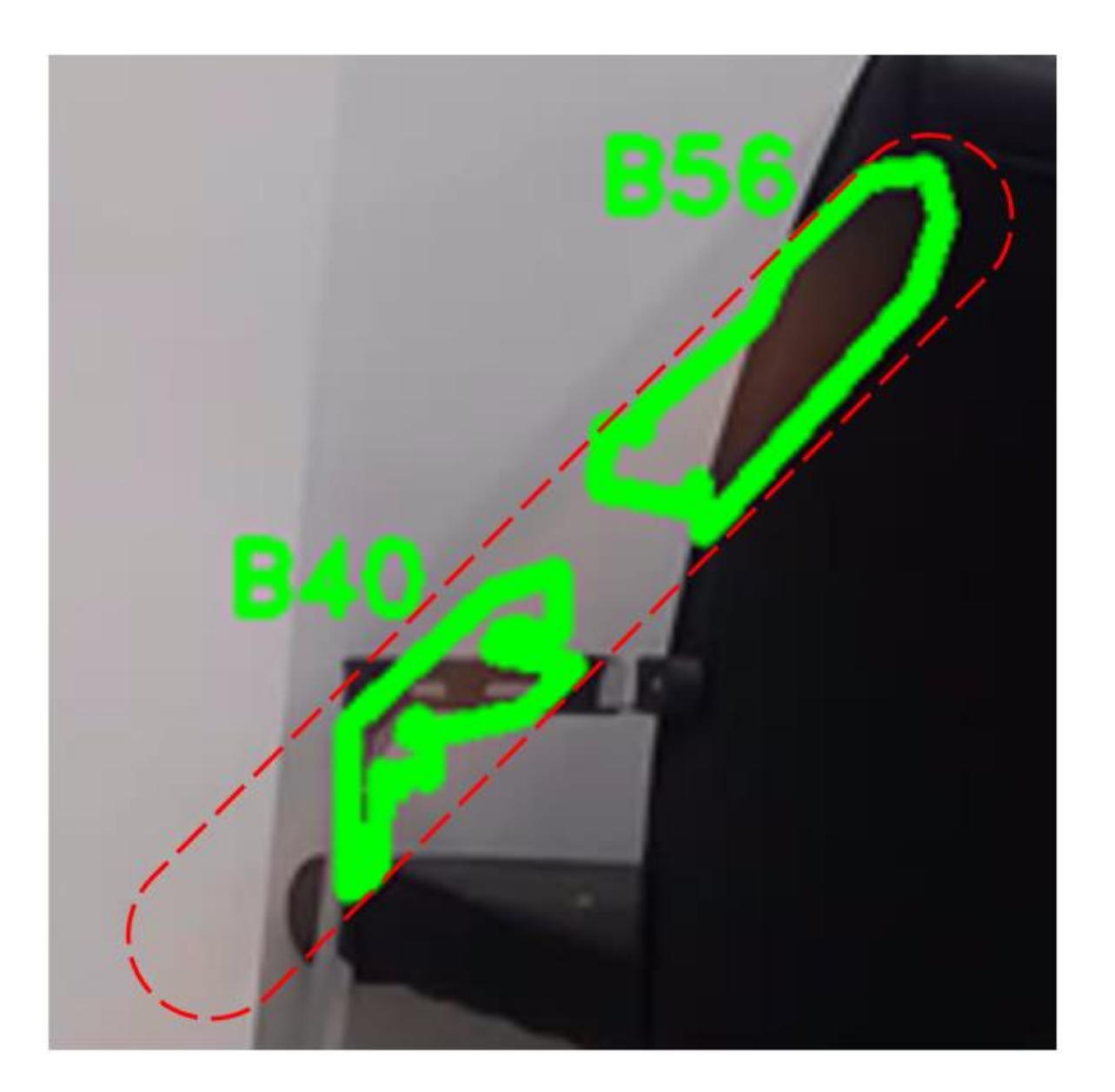
3.2.2. Candidate Block Detection

Sphere motion projection detection is a dynamic object detection problem that aims to distinguish the fixed background and the streak in an input image. As a standard method in dynamic object detection research, an interframe difference method is used to obtain moving target contours by differencing two frames. However, in the process of sphere detection, the interframe difference method faces two problems: (1) how to select ideal background frames and (2) how to distinguish the streak blocks from the noise blocks. To resolve the first problem, we improve the interframe difference method with a selection criterion for background. This criterion denies frames containing streak-like blocks and excessive noises. To resolve the second problem, we design a filter method to gradually filter out candidate blocks based on internal pixel intensity features and shape features. Figure 4 shows the overall process of our candidate block detection method.
We first focus on the selection of the ideal background. The interframe difference algorithm can figure out inconsistent pixel blocks between the input background frame and the current frame. However, when facing the output pixel blocks, we cannot tell from which input frame they come. In other words, if streak blocks are contained in the selected background frame but not in the current frame, the output result of the interframe difference algorithm also contains these blocks even if the current frame contains nothing. Similarly, noise blocks in the background frame will also appear in the result of the interframe difference algorithm. This problem leads to useless work and consumes a lot of computing resources. The idea of this part is to select frames that contain less noise as background frames, and we observed that a frame close to the current frame usually has less noise in terms of interframe difference method. Therefore, based on this observation, we propose to improve the interframe difference method by using the nearest frame with less noise as background. When detecting streaks in frame f t , the nearest frame f n that does not contain streaks and has less noise influence is used as the background. In the candidate block detection method, an image that does not contain any blocks with a similar shape ratio to streaks can be selected as a background frame for the following detections. Therefore, the difference D t is
D t x , y = f t x , y f n x , y
To distinguish backgrounds from streaks in image D t , a threshold T is used. When the difference D t x , y is greater than T, this pixel point is considered as part of the streak, otherwise is classified as the background:
R t x , y = 255 , D t x , y > T 0 , e l s e
Using the improved interframe difference method, we solved the background frame selection problem, thus significantly reducing the noise pollution between frames.
The improved interframe difference method ensures the independence of each frame but still cannot distinguish streak blocks from noise blocks in the foreground. When recognizing high-speed moving spheres, the camera position is kept fixed. As shown in Figure 5, Figure 5a is an original image containing a trajectory projection, and Figure 5b is a binarized image after using our proposed interframe difference method (the black area belongs to the background, and the white area belongs to the foreground). A foreground may contain three parts: streaks, images of a moving human body, and changes in ambient light. The improved interframe difference method cannot exclude the noise caused by the above moving human body and light changes. However, noise blocks and streak blocks have different characteristics, such as the external shape and the internal pixel intensity. Therefore, filtering the blocks step-by-step, with each step focusing on a specific characteristic, can exclude a large amount of noise. Based on this observation, we filter the foreground blocks in four steps based on the characteristics of the spherical motion projection to obtain candidate blocks.
We first extract blocks with suitable sizes. The area value A r e a of a streak in a captured image should be moderate, so large blocks should be excluded. Similarly, widely distributed small blocks should also be excluded. Thus, two boundary thresholds could be set:
A r e a T m a x _ a r e a , A r e a T m i n _ a r e a ,
The second filter condition limits the ratios of the area to the perimeter of a block and the area to the span. We define the span L of a block as the distance between the two furthest points on the contour. The contour can be simplified to a set P c o r n e r s that contains four corner points. Each corner point is closest to the image boundary.
P c o r n e r s = P x _ m i n , P y _ m i n , P x _ m a x , P y _ m a x
L = max P i P j 2 P i , P j P c o r n e r s
Since the block is a narrow strip, the ratio of Area to L 2 should be relatively small. A threshold T r a t i o _ a r e a is used to filter this ratio value.
A r e a L 2 T r a t i o _ a r e a
Similarly, the block is a narrow strip, and the ratio of perimeter P e r i to L should also be relatively small. However, perimeters obtained by Canny are usually larger than the actual values. This is because the boundaries of blocks obtained by Canny may be too tortuous in a local area, resulting in error corner points and false edges [17,18]. Therefore, to obtain perimeters with higher precision, the overly dense corner points should be simplified as one point. We transform the corner points obtained by Canny with size P l o y into optimized corner points with size r e P l o y . Then, based on the deviation of the two size values, we define a correction term ( P l o y r e P l o y ) 10 to calibrate P e r i . The ratio of the calibrated perimeter to the span should not exceed the threshold value T P e r i .
P e r i ( P l o y r e P l o y ) 10 L T P e r i
The third filtering condition is the pixel intensity feature inside a block. According to the profile fitting model in Section 3.2.1, the pixel intensity values on the profile can be fitted. Thus, the goodness of fit is taken as a criterion for judgment. The goodness of fit ( R s q ) for each profile is defined as
R s q = 1 ( y i y i ^ ) 2 ( y i y ¯ ) 2
We set a threshold T R s q for R s q . When R s q of this profile fit is greater than T R s q , the semi-ellipse fit is regarded as a valid fit, and the profile is valid. An ideal streak block is a family of valid profiles. Thus, the ratio of valid profiles in a valid block is greater than threshold T s t r e a k .
The last filtering condition ensures image borders do not trim any block. An accurate sphere motion reconstruction is based on a sufficiently complete streak, so the edges of the blocks should not intersect with the picture borders P b o r d e r _ p o i n t s .
P b o r d e r _ p o i n t s P c o r n e r s = Ø
After the above four filter steps, most noises could be filtered out, and the remains are regarded as candidate blocks. By these means, the number of candidate blocks can be reduced substantially. Figure 5c shows the blue contour of the candidate blocks after filtering. Compared with Figure 5b, most of the interferences of moving body and light changes are removed.

3.2.3. Concatenating Candidate Blocks

A precondition for reconstructing a sphere’s motion is to obtain its continuous projection. The more continuous the projection, the more contour points it contains that can be used to analyze the sphere’s position to reconstruct the motion. However, due to the high speed of the sphere’s movement, its projection is difficult to keep continuous. Taking Figure 6 for example, the image contains the contours of the streak candidate blocks identified using the method proposed in Section 3.2.1. Block B56 and B40 are discrete but belong to the same streak. To reconstruct the sphere motion, discrete blocks such as Block B56 and B40 must be concatenated.
The criterion for determining whether candidate blocks are from the same projection is to determine whether the blocks are collinear. Since candidate blocks belonging to the same projection must be collinear, obtaining the position and orientation of the blocks becomes a prerequisite for determining the collinearity of the blocks.
We first focus on the position and orientation of blocks. An ideal projection has roughly parallel lateral contours on both sides, with a narrow rectangle overall appearance. Therefore, the ideal candidate blocks that make up the projection could be similarly represented as rectangles. When the shape of the block is rectangular, it is easy to calculate the position and orientation of the block based on the properties of a rectangle. However, in practice, blocks obtained from a binarized image are irregularly shaped. Our idea for obtaining their positions and orientations is to convert the candidate blocks into rectangles.
By observing the candidate blocks, we found that the length information of the blocks is usually clear, but the width information is severely lost. Therefore, we first obtain the length information and then infer the approximate width of the blocks based on the areas. We take the following steps to convert candidate blocks into rectangles. First, the block is fitted using a straight line which is regarded as its orientation. The fitting line will intersect the ends of the contour, and the width of the rectangle equals the distance between the intersections. Then, the height of the rectangle is obtained as the ratio of the area to the width. Figure 7a is a simulation of a streak containing the irregular block and its fitting line. The irregular block is transformed into a rectangle in Figure 7b. The center of the rectangle replaces the position of the streak. Using the regularized rectangle instead of the block’s contour, we obtained each candidate block’s position and orientation.
After determining the position and orientation of each candidate block, we determine whether these blocks are collinear. In the ideal case, determining whether candidate blocks are collinear is a matter of determining whether their fitted straight lines overlap. However, due to the unavoidable error in the fitting result, the blocks on the same projection have different fitted lines. Thus, it is difficult to determine whether the blocks are collinear using the fitted straight lines alone. In this regard, we define a criterion for block collinearity.
For each rectangle along the direction, we defined the region between two diagonals as the collinear region for other blocks. When both blocks fall in each other’s collinear region, they are considered collinear. Taking Figure 7c for example, the collinear region of the green block contains the orange block. Meanwhile, the green block is also within the collinear region of the orange block. So these two blocks are collinear. In contrast, the blue block is not within the collinear regions of any block, so the blue block is not collinear with others.
Candidate blocks may be concatenated into more than one combination. Therefore, the combination that contains the most blocks is selected. Finally, the selected combination is extracted as the projection of the sphere’s motion trajectory and is re-fitted to obtain its overall position and orientation. Figure 7d is an example of the final combination.

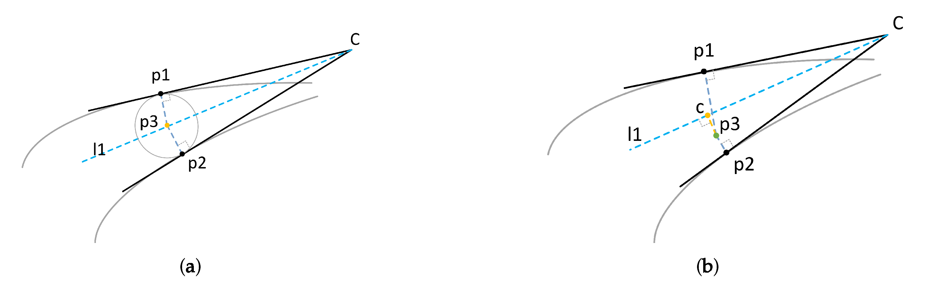
3.3. Matching Coupled Point Pairs

A coupled point pair consists of two points on the lateral contours and can be mapped to a sphere in space. Caglioti et al. [12] developed a contour point matching (CPM for short) method based on their cross section reconstruction geometry. However, their method focused on the slope of the lateral contours but tolerated the error of semi-ellipse fitting on the profile. To make up for the error, they added a coupled point pair searching process, which increased the complexity of the method but still failed to eliminate the error.
This paper proposes a novel method to match coupled point pairs based on the following observations. The perspective projection of a central curve (as introduced in Section 3.1) is a streak axis. When the sphere position is far enough away from the camera, the output shapes of the orthogonal projection and the perspective projection are highly similar. Thus, the streak axis is close to the central curve of the streak, which is formed by the midpoints of the contour point pairs output by the profile fitting model (as introduced in Section 3.2.1). Since the offset between these two curves can be ignored, our idea is to consider the central curve as the streak axis.
A coupled point pair is the image of two points on the same cross section. In projection, they are approximately symmetric with respect to the streak axis as the axis of symmetry [19]. Meanwhile, the points in the contour point pair output by the profile fitting model are also symmetric about the streak axis. Thus, a feasible idea is to consider the contour point pairs as coupled point pairs.
With the contours of the concatenated block detected in Section 3.2.2, the central curve could be initialized by fitting with a B spline curve. However, the initial central curve is fluctuating in slope while the real streak axis is a smooth curve with a slowly varying slope. The fluctuation in the initial central curve implies a large amount of error. Fortunately, we observed that such error could be eliminated using the profile fitting model proposed in Section 3.2.1: given a center point and its slope, the new center point output is closer to the actual center curve.
Based on the above observations, we propose an iterative coupled point pair matching method (ICPPM for short). The idea of the method is to obtain a more accurate smooth curve by iteration and then directly output a sequence of point pairs according to the profile fitting model in Section 3.2. In terms of specific operations, our iterative method consists of three parts: (1) initializing a central curve, (2) iterating the central curve, and (3) extracting coupled point pairs.
The first step is to initialize a central curve. The contour points at the ends of the block are not related to its orientation. As a result, the ends of the fitted curve are usually overfitted. Taking Figure 8 for example, the gray points are the origin contour obtained by Canny, and the red curve is the B spline fitting result of the contour. The curves in the blue boxes are overfitted and fluctuate sharply in their slope. To deal with the overfitting problem, the method sets a weight β for slope S to obtain the corrected slope V as follows:
V n = β S n + 1 β Q
where Q is the overall slope obtained in Section 3.2.2, and weight β is used as a smooth factor in considering the end of the block.
Then, the center curve is iterated to eliminate the error. In the iteration process, each center point is updated to a new location. The new center point’s location is determined by the parameter c in parameter set b in the profile fitting model. These new center points form a new center curve, which is then fitted with the B spline. Take Figure 9b–e as examples, the green curves are the center curve, and they become smoother in iterations.
After iterations, the center curve is finally determined. For each center point, two contour points could be obtained simultaneously with the profile fitting model, and these two contour points can be considered as a coupled point pair. Take Figure 9e for example, the red point is an axis point, and the two green points form a coupled point pair. Therefore, a sequence of coupled point pairs can be determined with the center curve.

3.4. Reconstructing Trajectories

Exploiting the coupled point pairs in Section 3.3, we can calculate the positions and velocities of the moving balls in the trajectory to reconstruct the trajectory.
In terms of positions, we first predict the pixel position of the sphere center and then exploit the pixel position and the couple point pair to map its ball position in space. By these means, a sequence of spheres’ canters can be obtained to construct the trajectory.
In terms of speed, the pixel intensity of the streak correlates with the ball moving speed. Based on the gray value of the center curve and the trajectory we reconstructed, we propose a motion velocity estimating method. The method calculates the duration that the background is covered by the sphere and the distance that the sphere moves during the duration. By these means, we can calculate the velocity corresponding to each coupled point pair.

3.4.1. Determining Ball Positions

Given the sphere radius and the imaging circle, the sphere’s position can be calculated using camera imaging principles. Unfortunately, the coupled points differ from the points at the ends of the diameter on the imaging circle. Thus, mapping the point pairs using the method in [4] will produce a significant error. Our idea is to use two points on the circumference of the circle to map the spatial position of the sphere, and these two points do not need to fall at the ends of a diameter. Fortunately, we observed that the sphere position could be determined with its image and the projecting plane that tangents to the surface of the sphere. Thus, exploiting this observation, we propose a novel sphere position mapping method which consists of three steps: (1) estimating the projecting line of the sphere’s center, (2) estimating the projecting plane that tangents to the surface of the sphere, and (3) estimating the sphere’s center with our projection model.
We first focus on estimating the projecting line of the sphere’s center. According to camera imaging principles, the projecting line could be derived from the projection of the sphere’s center. Through the single-view perspective projection model in [19], we find that the sphere center projection is roughly located at the intersection of the vertical line. Meanwhile, it is also close to the angular bisector of the angle formed by the tangents of the two points in a coupled pair. Taking Figure 10a for an example, p 1 and p 2 are coupled points on the lateral contours. Their tangents intersect at point c; l 1 is the angular bisector of the angle formed by C p 1 and C p 2 . The intersection p 3 of two vertical lines at p 1 , p 2 is the sphere center projection and falls on l 1 . The ideal intersection is p 3 as the projection should be close to l 1 . However, due to calculation deviation, p 3 may deviate significantly from l 1 , resulting in a large error in the sphere mapping result. To eliminate the deviations, the projection of point p 3 onto the line is regarded as the projection of the sphere’s center. Taking Figure 10b as an example, p 3 deviates significantly from l 1 , and thus its projection c is considered as the projection of the sphere’s center.
After correcting the image for distortion, a mapping can be established between the pixel points and their spatial coordinates. Given a pixel point ( u , v ) , we can map its projecting line ( X , Y , Z ) in 3D space and vice versa. The conversion relationship is as follows:
A u v 1 = f / d x 0 u 0 0 0 f / d y v 0 0 0 0 1 0 X Y Z 1 = K 0 X Y Z 1
where K is the camera intrinsic matrix. Using Equation (16), the projecting line of the sphere’s center is determined.
We then estimate the projecting plane that tangents to the sphere’s surface. According to the camera imaging principle, the projecting plane could be derived from a line that tangents to the sphere’s image. Using Equation (16), a straight line y = θ 0 + θ 1 x in the image plane is capable of mapping to a plane in space. The conversion relationship is as follows:
θ 1 f d x X f d y Y + Z ( θ 0 v 0 + θ 1 u 0 ) = 0
Therefore, the two projecting planes that tangent to the surface of the sphere can be determined with C p 1 and C p 2 .
With the projecting line and the projecting planes, our projection model can determine the corresponding sphere position. Our projection model is shown in Figure 11. In Figure 11a, point c is the projection of the sphere’s center in the image plane. O denotes the optical center of the camera; c O is the projecting line of the sphere’s center P c ; c O can be determined with Equation (16). C p 1 and C p 2 are the tangents of the coupled points p 1 , p 1 . Plane T is the mapping of C p 2 with Equation (17). In Figure 11b, since the projecting line of the sphere’s center and the projecting plane that tangents to the surface of the sphere are fixed, the 3D position of the sphere with a constant radius is determined.

3.4.2. Determining Ball Speed

The instantaneous speed is usually the average velocity of a moving object over a short time interval, and we observed that each pixel on the streak axis corresponds to a ball’s center in space, and the ball image would overlap the pixel for a while. In this time span, the ball would contact the projecting line that goes through the pixel. Therefore, we propose a ball velocity calculation model which estimates the speed of the sphere with the time span and the movement distance.
We first focus on the time span. The pixel intensity T x y at pixel ( x , y ) in the image is a combination of the background pixel intensity B x y and the sphere pixel intensity C [12]. Given exposure duration t 1 and pixel intensity T x y and B x y , time span t 2 of pixel ( x , y ) covered by the image of the sphere could be obtained with the following equation:
t 2 = T x y B x y t 1 B x y C
Exploiting the above equation, we can determine the time span of a pixel on the streak axis overlapped by the ball image.
At the start and end of the time span t 2 , the sphere tangents to the projecting line that goes through the pixel I x y . We propose a model to calculate the move distance based on this property. The model is shown in Figure 12. In Figure 12a, projecting line L 2 goes through I x y in the image plane and optical center O of the camera, intersecting the axis of the ball trajectory at P t . In Figure 12b, P s and P e is the image of the ball center, and L 1 is the image of L 1 . In t 2 , the sphere’s image moves from P s to P e . This means that the sphere in space moves from P s to P e along direction L 1 . I x y locates at the tangent point of the two circles, which are the images of sphere P s and sphere P e , so these two spheres also tangent to L 2 .
With the ball positions obtained in Section 3.4.1, the sphere’s moving direction ( L 1 ) is definite. L 2 is also definite according to Equation (16). Thus, the angle β between L 1 and L 2 can be determined. Then, given the raids R of the sphere, the distance S from P s to P e is 2 R sin β . Thus, the speed of the sphere with center P t is S t 2 .

4. Experimental Results

In Section 3, we present a method of sphere motion recognition and recovery. Firstly, the method detects the streak of the sphere motion in the picture (as mentioned in Section 3.2); secondly, based on the detected streak, the method calculates the spatial position of the sphere and reconstructs the trajectory (as mentioned in Section 3.4.1); finally, the method outputs the velocity and direction of the sphere motion during the exposure time (as mentioned in Section 3.4.2). For all these three parts, we designed the corresponding experiments, respectively. Therefore, our method was evaluated with three parts: (1) streak detection, (2) trajectory reconstruction, and (3) motion prediction.
We verified the reliability and practicality of our method with videos recorded in different experimental scenarios with different light intensities. On a tripod, we recorded a fast-flying black ping pong ball with a 96 MPixel (1280 × 720) digital camera. The digital camera was set to auto-exposure, and the exposure duration was automatically adjusted from 1.25 ms to 40 ms. In these videos, the sphere motions had different directions and velocities.
The thresholds and weights in the experiment are listed in Table 1.

4.1. Streak Detection Results

We evaluated the contour acquiring method of Section 3.2. This method eliminates noise from the image to extract streaks. Thus, we tested our method with images containing both noises and streaks and observed whether streaks were detected and how complete they were.
Streak detection can be considered a binary classification problem where an image is either classified as containing a streak or not containing a streak. The confusion matrix is a means to evaluate the performance of the algorithms involved in such classifications [20,21,22]. The confusion matrix elements encapsulate the following information.
  • True Positive (TP): The TP defines those images which are verified as containing a streak and also identified by the method as containing a streak.
  • True Negative (TN): The TN defines those images which are verified as not containing a streak and also identified by the method as not containing a streak.
  • False Positive (FP): The FP defines those images which are verified as not containing a streak and also identified by the method as containing a streak.
  • False Negative (FN): The FP defines those images which are verified as containing a streak and also identified by the method as not containing a streak.
Then, the precision, recall, and F1-score are further utilized to compute performance metrics for our method. The precision gives us the percentage of the correct prediction from our method’s total prediction. Recall gives us the percentage of how many total positive cases are predicted correctly with our method. Finally, F1-score gives the combined result of precision and recall. It is a harmonic mean of precision and recall. These metrics are calculated as:
precision = TP TP + FP
recall = TP TP + FN
F 1 _ score = 2 precision recall precision + recall
To measure the streak integrity of detected streaks, we defined the length of a concatenated streak block (as introduced in Section 3.2.3) as its predicted length (PL) and the length manually marked as true length (TL). Then, the streak integrity for each streak could be calculated as PL TL .
We recorded 22 shots in 5 scenes with different backgrounds and light intensities. The recorded video consisted of 82 frames containing the streaks and 90 frames without the streaks.
Table 2 shows the confusion matrix of the result of distinguishing streaks. The precision was 0.987, the recall was 0.951, and the F1-score was 0.969. In the results, four streaks were not detected. The reason was that the background was too dark, or the background color was similar to the sphere. In these cases, the sphere would blend completely into the background. Another reason was that the color variation of the background was too rich (the background was full of characters), resulting in failures in streak profile fitting (as introduced in Section 3.1).
Meanwhile, in Table 2, there is a case of FP. When marking the sample manually, we excluded streaks that intersect the image border. However, during detection, the trajectory may be intermittent. The streak blocks that did not intersect the border were identified as valid streaks by our method. The extra streak was a block of an intermittent streak, and thus, the error could be neglected.
Figure 13 shows an example of the candidate block detection process. These figures contain a blur streak. Figure 13a is cropped from an original image, which contains a gray streak. Figure 13b is the output of the interframe difference method and contains a lot of noise. In Figure 13c, they are presented in the form of blocks. In the next steps, they were filtered step-by-step using the method in Section 3.2.2. Figure 13d shows the blocks that passed through the first filter. The blocks with small sizes were removed; most of them were image noises. Figure 13e shows the blocks that passed through the second filter. This filter selected blocks based on their shapes. Compared to Figure 13d, the backboard of the chair was removed. Figure 13f shows that only one block passed through the third filter. This filter selected blocks based on their pixel intensities and successfully categorized the waving arm as noise. Through the above filtering, we successfully obtained the candidate block.
The average integrity of the streaks extracted by the contour extraction method was 87.7%. This means that our streak extraction method extracted most of the contours of these streaks and provided sufficient lateral contour points for trajectory reconstruction.
Streak detection methods are strongly coupled with problem scenarios. For example, streak detection methods used in scenarios of multiple high frame rate cameras cannot be used in scenarios of monocular low frame rate cameras. This makes it hard to compare the performance of various streak detection methods. In response to such challenges, we choose to compare the performance of our proposed streak detection method with other methods applied in different scenarios by analyzing the reported performances in their original research.
Comparing our method with the existing methods in [3,4,7], we can find that the detection rate of our algorithm is slightly lower than those methods (about 2% to 4%). The reasons for this phenomenon are as follows: firstly, these methods are based on multiple high frame rate cameras, while this paper used only one low frame rate monocular camera. Thus, the trajectory images we obtained are much blurrier than theirs. Secondly, they focus only on the detection rate (i.e., recall), while we fully consider the recall and precision. Therefore, our experimental data are closer to the actual application. Meanwhile, the detection rate of our method is better than that of the method in [6], which indicates that our method is more suitable for sphere detection than the deep-learning-based algorithm on blurred images. The above comparison shows that the sphere detection effect of our method is satisfactory.

4.2. Trajectory Reconstruction Results

Comparisons were made using our trajectory reconstruction method with the original method in [11,12]. Since the streak axis is able to reflect the matching effect of the point pairs, we first compared these streak axes output by CPM and ICPPM (both are introduced in Section 3.3) before comparing the reconstruction error.
The precise streak axes should be smooth, so they could be well fitted with four-order B splines. Therefore, to compare the streak axes, we compared their goodness of fit ( R 2 ). For each streak axis point ( x , y ) , x was the input value, y was the true value, and y ^ was the predicted value in the spline fitting process. Then, the total sum of squares (TSS), the residual sum of squares (RSS), and R 2 were calculated as:
TSS = i = 1 n ( y i y ¯ ) 2
RSS = i = 1 n ( y i y ^ ) 2
R 2 = 1 RSS TSS
The real position value of a trajectory was difficult to determine. We found that given the trajectory’s vertical plane, the trajectory’s position could be determined based on camera imaging principles. For this reason, we used ArUco [23] to mark vertical planes beforehand and then threw the sphere along the marked vertical planes. By this means, we obtained the real position of each trajectory. An easy way to represent the position of a trajectory was to use the positions of the two ends of the trajectory. Therefore, we defined the trajectory reconstruction error as the average distance from the ends of the trajectory to the vertical plane.
In the experiment, we divided the streak axes of the detected streaks into four length intervals and calculated average R 2 for each interval as reported in Table 3. It can be observed that our ICPPM outperforms CPM in different streak length intervals, especially for short streaks. This means that the streak axis optimization method in Section 3.3 is effective.
Figure 14 lists three comparisons. The streaks are marked in three cropped images. CPM and ICPPM use these streaks as data sources and output their axes. The first set of comparisons used a short streak in Figure 14a. By comparing Figure 14a,b, it can be confirmed that our ICPPM method performs much better when the streak is short.The second set of comparisons have used a medium-length streak in Figure 14d. By comparing Figure 14e,f, we can observe that our method has better results at the end points of the streak. This is due to the improvements we made to the axis fitting at the ends of the streak in Section 3.3. The third set of comparisons have used a long streak in Figure 14g. By comparing Figure 14h,g, We can observe that both methods have good results. However, our ICPPM has output more axis points, which help to improve the accuracy of the trajectory reconstruction.
Then, we focused on the reconstruction error. We divide the 78 trajectories into 4 sets based on their distance (measured as multiples of the ball radius) from the camera. For each set, we compared the average error of our trajectory reconstruction method and the methods used in [11,12].
In Table 4, the result shows the reconstruction error for different methods at different distances. The method in [11] used ellipses to fit the contours at both ends of the streak. Due to excessive blurring at the ends of the streaks, the fit results were not stable. Thus, the error fluctuated widely. The method in [12] and our method used the coupled point pairs extracted from lateral contours, performing better in reconstructing trajectory from blurred images than the method in [11]. Compared to method [12], our method performed better due to the optimization of the point pair acquisition method in Section 3.3 and the use of a new spatial mapping method in Section 3.4.1.
Taking Figure 15 for an example, these figures contain a blur streak. The green points in Figure 15a are the coupled points. Compared to the output of Canny in Figure 13b, the edges here are smoother and more accurate. In Figure 15b, for the convenience of finding their first order derivative, the coupled points are projected into their spline curves. Finally, Figure 15c is the reconstructed trajectory using our sphere position mapping method.

4.3. Motion Prediction Results

This experiment was done to evaluate the accuracy of our method for predicting the velocity and direction of sphere motion. We compared the errors in direction and velocity between our approach and the methods in [11,12].
The predicted direction P D of a trajectory was the line through its end points in the camera coordinate system. The direction prediction error φ d i r e c t i o n was the vectorial angle between P D and the true direction T D that was marked manually on vertical planes. Thus, φ d i r e c t i o n could be calculated as:
φ d i r e c t i o n = arccos P D · T D P D × T D
We defined the error in velocity as the ratio of the speed difference to the true velocity (TV). The true velocity equaled the distance between the two ends of the trajectory divided by the duration of the exposure. Different methods have contributed various approaches to calculating speed. The velocity prediction of the method in [11] was calculated based on the distance traveled and the duration of exposure. In contrast, our method and the method in [12] output predicted velocity (PV) that was the median of the velocity prediction sequence. Then, the velocity prediction error could be calculated as:
φ v e l o c i t y = T V P V T V
We used 45 images that contained streaks to test these methods. We classified trajectory orientations according to their angle size to the camera’s imaging plane. Table 5 shows three methods’ direction prediction errors. It can be observed that under different trajectory orientations, the prediction error of our method was the smallest compared with the other two methods. As the trajectory deviated from the camera’s imaging plane, the error of our method and method in [12] in predicting the trajectory direction increased. This was because sphere imaging was not sensitive to changes in sphere depth information relative to lateral or longitudinal motion. Therefore, the sphere should move parallel to the imaging plane as much as possible to ensure accurate direction prediction.
Table 6 shows the velocity prediction errors for the three methods. It can be observed that our method was better than the other methods in different speed intervals. When the speed was below 12 m/s, all three methods had significant errors in their predictions. The streak length increased with the ball speed, and longer streaks would provide more coupled pair points for analyzing the direction and velocity. Thus, the performances of our method and the method in [24] became progressively better as the speed increased.

4.4. Discussion

Our method was evaluated through several experiments. The result shows that the F1-score of distinguishing streaks was 0.97, and the average integrity of the extracted streaks was 87.7%. Furthermore, our trajectory reconstruction method could provide better results than existing approaches.
As most monocular-vision-based approaches do, our proposed method also faced the problem of outputting inaccurate results on the moving direction prediction. To solve this problem, it is necessary to increase the number of cameras in different locations, but this will increase the cost.

5. Conclusions

In this paper, we proposed a novel method for the recognition and recovery of sphere motions. The method filters out candidate blocks from noises and concatenates these blocks into a streak. To obtain ball position sequence in space, the method first introduced a novel coupled point pairs matching method, which exploits streak axes optimized by iteration and then presented a model to map coupled point pairs to ball 3D positions. With ball position sequences, we could finally obtain ball moving speed.
The main contributions of this paper are as follows: (1) We proposed an improved interframe difference algorithm to automatically select the nearest optimal background frame, thus reducing the effect of noise on the results of frame difference. (2) We proposed a new coupled point pairs matching method, which iterates to eliminate the problem of streak axis fluctuation due to image blurring and to calculate the actual position of the streak axis. The method outputs an accurate coupled point pair sequence. (3) We proposed a novel sphere space mapping method that is based on coupled point pairs. The method successfully eliminates the computational error of the sphere spatial position brought by the distortion of sphere imaging, and (4) we proposed a new model for recovering the direction and velocity of sphere motion. With the pixel positions and the trajectory, the model determines the velocity of the sphere motion. This model is simple but effective and does not require complex equipment or deployment.
We have noticed a trend to use deep learning for trajectory reconstruction. However, traditional deep learning methods could hardly form a deep understanding of the trajectory reconstruction problem. Compared to deep learning methods, an essential advantage of our approach is that we break down the trajectory reconstruction problem into three explicit sub-problems, which could help inspire new traditional and deep learning methods toward trajectory reconstruction. Meanwhile, a deep learning method will help solve our proposed sub-problems. Thus, one of our critical future works is to apply deep learning methods to the three sub-problems that we have pointed out.
Our proposed method does not require the complex point pair matching process (as methods in [12,19]). However, the time cost of the new method is not reduced due to the iterations used in the streak axis optimization process. Thus, another future work is to reduce the time cost brought by the optimization process to improve performance.

Author Contributions

Conceptualization, Y.Z. (Yin Zhang) and Y.Z. (Yuli Zhao); methodology, W.Z. and Y.Z. (Yin Zhang); software, W.Z.; validation W.Z., Y.Z. (Yin Zhang), and Y.Z. (Yuli Zhao); formal analysis, W.Z. and Y.Z. (Yin Zhang); investigation, B.Z.; resources, B.Z.; data curation, W.Z.; writing—original draft preparation, W.Z.; writing—review and editing, Y.Z. (Yin Zhang) and Y.Z. (Yuli Zhao); visualization, W.Z.; supervision, Y.Z. (Yin Zhang) and Y.Z. (Yuli Zhao), project administration, B.Z.; funding acquisition, Y.Z. (Yuli Zhao) and B.Z. All authors have read and agreed to the published version of the manuscript.

Funding

This work was supported by the Key Project of National Natural Science Foundation of China (U1908212), the Central government guided local science and Technology Development Fund Project (1653137155953), the Liaoning Province “takes the lead” science and technology research project (2021jh1/10400006), and the Liaoning Provincial Natural Science Foundation of China (2022-MS-124).

Institutional Review Board Statement

Not applicable.

Informed Consent Statement

Not applicable.

Data Availability Statement

Data is available on request.

Conflicts of Interest

The authors declare no conflict of interest.

References

  1. Shugar, D.H.; Jacquemart, M.; Shean, D.; Bhushan, S.; Upadhyay, K.; Sattar, A.; Schwanghart, W.; McBride, S.; de Vries, M.V.W.; Mergili, M.; et al. A massive rock and ice avalanche caused the 2021 disaster at Chamoli, Indian Himalaya. Science 2021, 373, 300. [Google Scholar] [CrossRef] [PubMed]
  2. Ahrens, E.T.; Bulte, J.W.M. Tracking immune cells in vivo using magnetic resonance imaging. Nat. Rev. Immunol. 2013, 13, 755–763. [Google Scholar] [CrossRef] [PubMed]
  3. Wen, H.; Xiao, Z.; Li, Y.; Xu, Y. A Vision System for Shot Tracking and Thrown Distance Measurement. In Proceedings of the 2020 7th International Conference on Information Science and Control Engineering (ICISCE), Changsha, China, 18–20 December 2020; pp. 1647–1651. [Google Scholar]
  4. Wang, S.; Xu, Y.; Zheng, Y.; Zhu, M.; Yao, H.; Xiao, Z. Tracking a Golf Ball with High-Speed Stereo Vision System. IEEE Trans. Instrum. Meas. 2019, 68, 2742–2754. [Google Scholar] [CrossRef]
  5. Jia, L.Q.; Liu, H.M.; Wang, Z.H.; Chen, H. An effective non-HT circle detection for centers and radii. In Proceedings of the 2011 International Conference on Machine Learning and Cybernetics, Guilin, China, 12 September 2011; Volume 2, pp. 814–818. [Google Scholar]
  6. Wu, D.; Xiao, A. Deep Learning-Based Algorithm for Recognizing Tennis Balls. Appl. Sci. 2022, 12, 12116. [Google Scholar] [CrossRef]
  7. Jung, J.; Park, H.; Kang, S.; Lee, S.; Hahn, M. Measurement of Initial Motion of a Flying Golf Ball with Multi-Exposure images for Screen-golf. IEEE Trans. Consum. Electron. 2010, 56, 516–523. [Google Scholar] [CrossRef]
  8. Zhang, Y.h.; Wei, W.; Yu, D.; Zhong, C.w. A tracking and predicting scheme for ping pong robot. J. Zhejiang-Univ. Sci. Comput. Electron. 2011, 12, 110–115. [Google Scholar] [CrossRef]
  9. Wen, B.J.; Chang, C.R.; Lan, C.W.; Zheng, Y.C. Magnus-Forces Analysis of Pitched-Baseball Trajectories Using YOLOv3-Tiny Deep Learning Algorithm. Appl. Sci. 2022, 12, 5540. [Google Scholar] [CrossRef]
  10. Lin, H.Y.; Chang, C.H. Speed measurement of spherical objects using an off-the-shelf digital camera. J. Electron. Imaging 2008, 17. [Google Scholar] [CrossRef]
  11. Boracchi, G.; Caglioti, V.; Giusti, A. Ball Position and Motion Reconstruction from Blur in a Single Perspective Image. In Proceedings of the 14th International Conference on Image Analysis and Processing (ICIAP 2007), Modena, Italy, 10–14 September 2007; pp. 87–92. [Google Scholar]
  12. Caglioti, V.; Giusti, A. Recovering ball motion from a single motion-blurred image. Comput. Vis. Image Underst. 2009, 113, 590–597. [Google Scholar] [CrossRef]
  13. Rezvankhah, S.; Bagherzadeh, A.A.; Moradi, H.; Araabi, B.N. A real-time velocity estimation using motion blur in air hockey. In Proceedings of the 2012 IEEE International Conference on Robotics and Biomimetics (ROBIO), Guangzhou, China, 11–14 December 2012; pp. 1767–1772. [Google Scholar]
  14. Ren, J.; Orwell, J.; Jones, G.; Xu, M. A general framework for 3D soccer ball estimation and tracking. In Proceedings of the 2004 International Conference on Image Processing, ICIP ’04, Singapore, 24–27 October 2004; Volume 3, pp. 1935–1938. [Google Scholar]
  15. Caglioti, V.; Giusti, A. Reconstruction of canal surfaces from single images under exact perspective. In Proceedings of the 9th European Conference on Computer Vision (ECCV 2006), Graz, Austria, 7–13 May 2006; pp. 289–300. [Google Scholar]
  16. Cheng, X.; Sun, J.; Zhou, F. A Fully Convolutional Network-Based Tube Contour Detection Method Using Multi-Exposure Images. Sensors 2021, 21, 4095. [Google Scholar] [CrossRef] [PubMed]
  17. Liu, T.; Liu, R.; Ping-Zeng; Pan, S.W. Improved Canny Algorithm for Edge Detection of Core Image. Open Autom. Control Syst. J. 2015, 6, 426–432. [Google Scholar] [CrossRef]
  18. Zhang, C.; Zhang, N.; Yu, W.; Hu, S.; Wang, X.; Liang, H. Improved Canny-based algorithm for image edge detection. In Proceedings of the 2021 36th Youth Academic Annual Conference of Chinese Association of Automation (YAC), Nanchang, China, 28–30 May 2021; pp. 678–683. [Google Scholar]
  19. Cheng, X.; Sun, J.; Zhou, F.; Xie, Y. Shape from apparent contours for bent pipes with constant diameter under perspective projection. Measurement 2021, 182, 109787. [Google Scholar] [CrossRef]
  20. Muhuri, A.; Gascoin, S.; Menzel, L.; Kostadinov, T.S.; Harpold, A.A.; Sanmiguel-Vallelado, A.; Lopez-Moreno, I.J. Performance Assessment of Optical Satellite-Based Operational Snow Cover Monitoring Algorithms in Forested Landscapes. IEEE J. Sel. Top. Appl. Earth Obs. Remote. Sens. 2021, 14, 7159–7178. [Google Scholar] [CrossRef]
  21. Raskar, R.; Dhillon, R.; Kapa, S.; Pahwa, D.; Falgas, R.; Sinha, L.; Prasad, A.; Singh, A.; Nuzzo, A.; Iyer, R.; et al. Comparing manual contact tracing and digital contact advice. arXiv 2020, arXiv:2008.07325. [Google Scholar]
  22. Demir, I.; Koperski, K.; Lindenbaum, D.; Pang, G.; Huang, J.; Basu, S.; Hughes, F.; Tuia, D.; Raskar, R. DeepGlobe 2018: A Challenge to Parse the Earth through Satellite Images. In Proceedings of the IEEE Computer Society Conference on Computer Vision and Pattern Recognition Workshops (CVPRW), Salt Lake City, UT, USA, 18–22 June 2018. [Google Scholar]
  23. Garrido-Jurado, S.; Munoz-Salinas, R.; Madrid-Cuevas, F.J.; Marin-Jimenez, M.J. Automatic generation and detection of highly reliable fiducial markers under occlusion. Pattern Recognit. 2014, 47, 2280–2292. [Google Scholar] [CrossRef]
  24. Pingali, G.; Opalach, A.; Jean, Y. Ball tracking and virtual replays for innovative tennis broadcasts. In Proceedings of the Proceedings 15th International Conference on Pattern Recognition. ICPR-2000, Barcelona, Spain, 3–7 September 2000; Volume 4, pp. 152–156. [Google Scholar]
Figure 1. The overall steps of our sphere motion reconstruction method.
Applsci 13 01513 g001
Figure 2. Workflow of our sphere motion reconstruction method.
Applsci 13 01513 g002
Figure 3. Fitting the intensity values along the profile using a semi-ellipsoid.
Applsci 13 01513 g003
Figure 4. The overall process of our candidate block detection method.
Applsci 13 01513 g004
Figure 5. Detecting candidate blocks from an original image: (a) input an actual photograph; (b) binarize the image with our proposed interframe difference method. (c) extract candidate blocks (wrapped in blue curves) with filters.
Applsci 13 01513 g005
Figure 6. Due to noise, a trace is identified as multiple discrete blocks. Block B56 and B40 should belong to the same streak (in red dashed line).
Applsci 13 01513 g006
Figure 7. Our method for concatenating candidate blocks: (a) a simulation of a irregular streak; (b) transform the irregular block into a rectangle; (c) determine the collinear regions of the block; (d) the final combination concatenated by candidate blocks.
Applsci 13 01513 g007
Figure 8. The central curve fitted with contour points. Good fit in the middle region, but overfitting on both sides.
Applsci 13 01513 g008
Figure 9. The iteration process of the central curve of a streak: (a) the original image containing a trajectory projection; (b) the initialized central curve (the green curve); (c) the central curve after one iteration; (d) the central curve after two iterations; (e) the final central curve after three iterations. The blue points will be matched as coupled point pairs.
Applsci 13 01513 g009
Figure 10. Estimation of the projection position of the center of the ball that the coupled point pair corresponds: (a) the intersection falls on the angular bisector in ideal situation; (b) the intersection deviates significantly from the angular bisector.
Applsci 13 01513 g010
Figure 11. Mapping a coupled point pair to a ball in space: (a) the overall reconstruction geometry. The coupled point pair formed by p 1 and p 2 is mapped to the ball centered on P c ; (b) determination of ball center position. The sight line overlaps with the plane T.
Applsci 13 01513 g011
Figure 12. Ball velocity calculation model: (a) geometric principles of axis ( L 1 ) imaging. The axis point P s is projected to I x y on camera image plane; (b) the images of axis and balls that tangent to the projecting line ( L 2 ). The images are on the camera image plane.
Applsci 13 01513 g012
Figure 13. Intermediate results of our candidate block detection method: (a) an original image containing the streak of a black moving ball; (b) the output of the interframe difference method. The white part is the foreground, which contains a streak and various types of noises; (c) initial blocks for filtering out the true streak; (d) the blocks that pass through the first filter. These blocks have suitable sizes; (e) the blocks that pass through the second filter. These blocks have suitable shapes; (f) the block that passes through the third filter. The internal pixel intensity of this block is passable and is considered a candidate block.
Applsci 13 01513 g013
Figure 14. Comparison of the streak axes of CPM and ICPPM: (a) a cropped image that contains a short streak; (b) the streak axis (disorder green points in image) of CPM; (c) the streak axis of our ICPPM; (d) a cropped image that contains a medium-length streak; (e) the streak axis of CPM; (f) the streak axis of our ICPPM; (g) a cropped image that contains a long streak; (h) the streak axis of CPM; (i) the streak axis of our ICPPM.
Applsci 13 01513 g014
Figure 15. The result of our sphere position mapping method: (a) original coupled points; (b) coupled points projected into their spline curves; (c) a reconstructed trajectory using our sphere position mapping method.
Applsci 13 01513 g015
Table 1. The thresholds and weights in our experiment.
NameValue
T3
T m a x _ a r e a 15,000
T m i n _ a r e a 150
T r a t i o _ a r e a 0.33
T P e r i 3.1
β 0.8
Table 2. The confusion matrix.
True Label
Has streakNo streak
Predict LabelHas streak78 (TP)1 (FN)
No streak4 (FP)89 (TN)
Table 3. The average R 2 of the spline fit for streak axes.
Streak Length Interval (pixel) R 2
CPMICPPM
60–1200.4170.979
120–1600.6320.917
160–2000.7310.940
200+0.8290.990
Table 4. The average errors (multiples of the ball radius R) of the trajectory reconstructions.
Distance (R)Average Error (R)
Method in [11]Method in [12]The Proposed Method
20–11033.221.520.7
110–13037.422.523.6
130–15079.640.725.2
150–20042.730.627.0
Table 5. The average errors of the predicted directions.
Angle ( ) Direction Prediction Error ( )
Method in [11]Method in [12]The Proposed Method
0–1057.798.0415.17
10–2057.3117.1011.71
20–3052.7426.5225.63
Table 6. The average errors of the predicted velocities.
Speed (m/s) Velocity Prediction Error
Method in [11]Method in [12]The Proposed Method
3–113.243.681.99
11–172.260.950.72
17–221.350.960.64
22–281.060.590.22
Disclaimer/Publisher’s Note: The statements, opinions and data contained in all publications are solely those of the individual author(s) and contributor(s) and not of MDPI and/or the editor(s). MDPI and/or the editor(s) disclaim responsibility for any injury to people or property resulting from any ideas, methods, instructions or products referred to in the content.

