
Influence of Perfluorooctanoic Acid on Structural, Morphological, and Optical Properties of Hybrid Silica Coatings on Glass Substrates

 , , ,
, , ,  , , ,
, , ,
Abstract
:1. Introduction
2. Experimental Section
2.1. Materials
2.2. Preparation
2.3. Methods
3. Results and Discussion
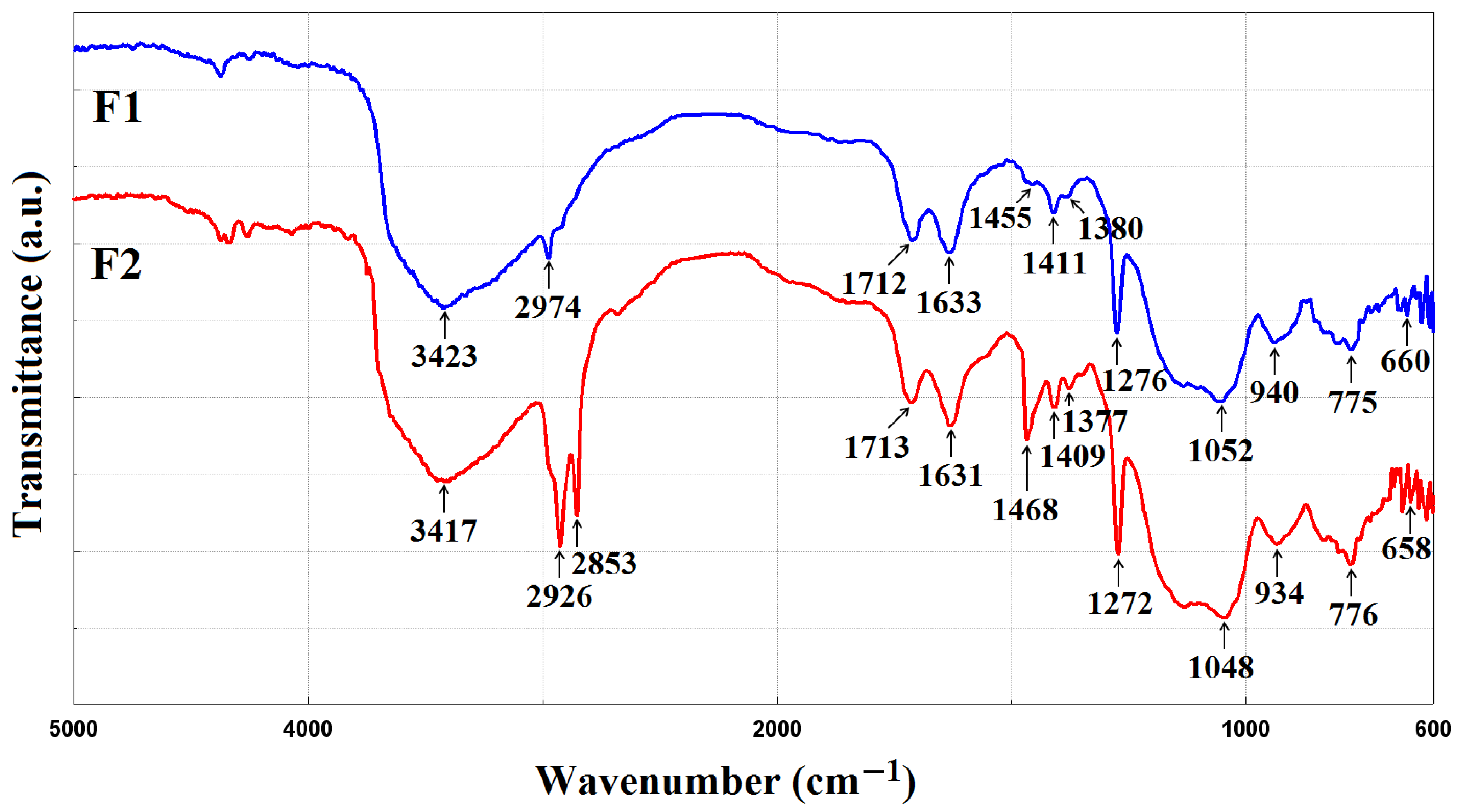
3.1. FTIR Spectoscopy
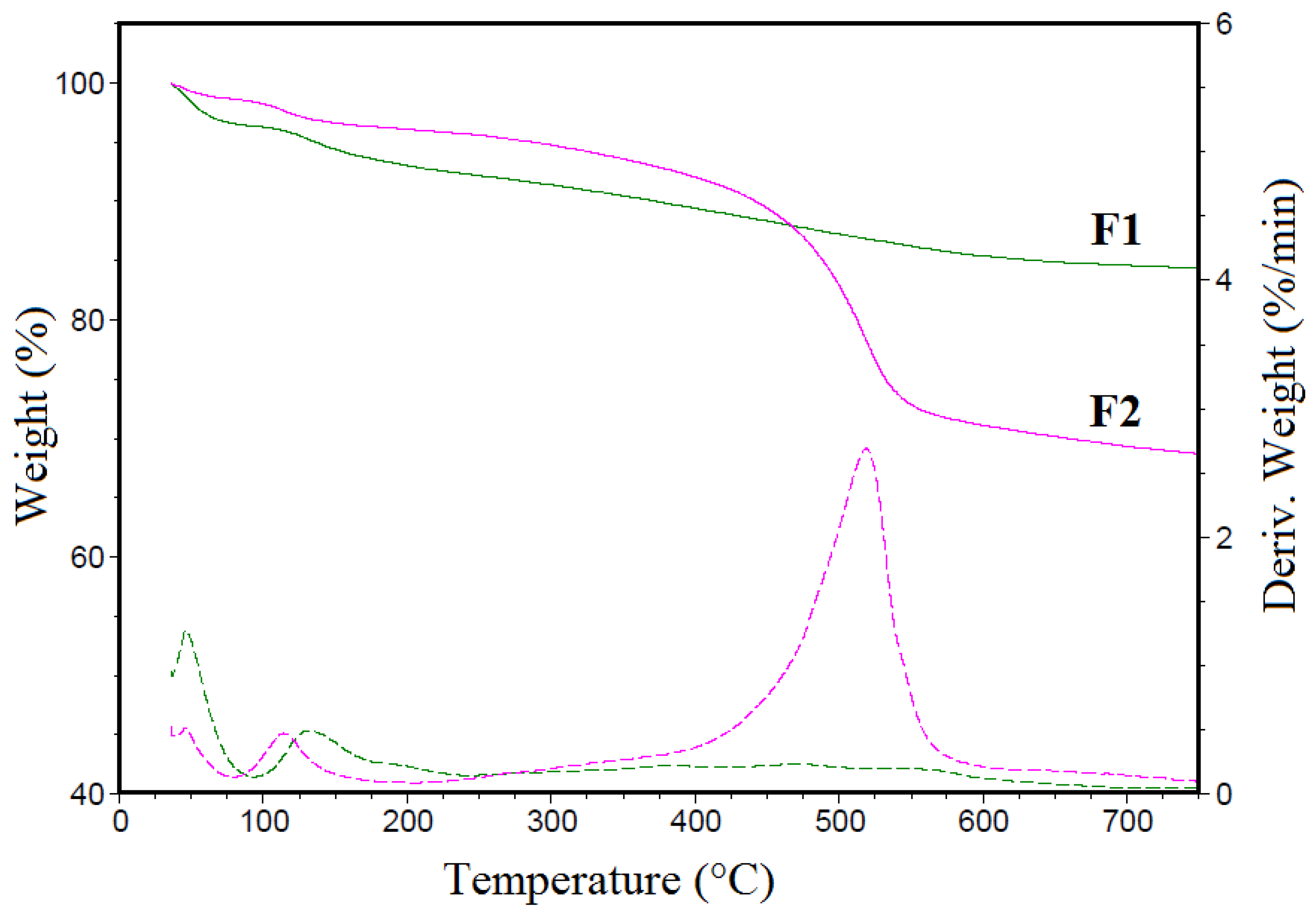
3.2. TGA Analysis
3.3. TEM Analysis
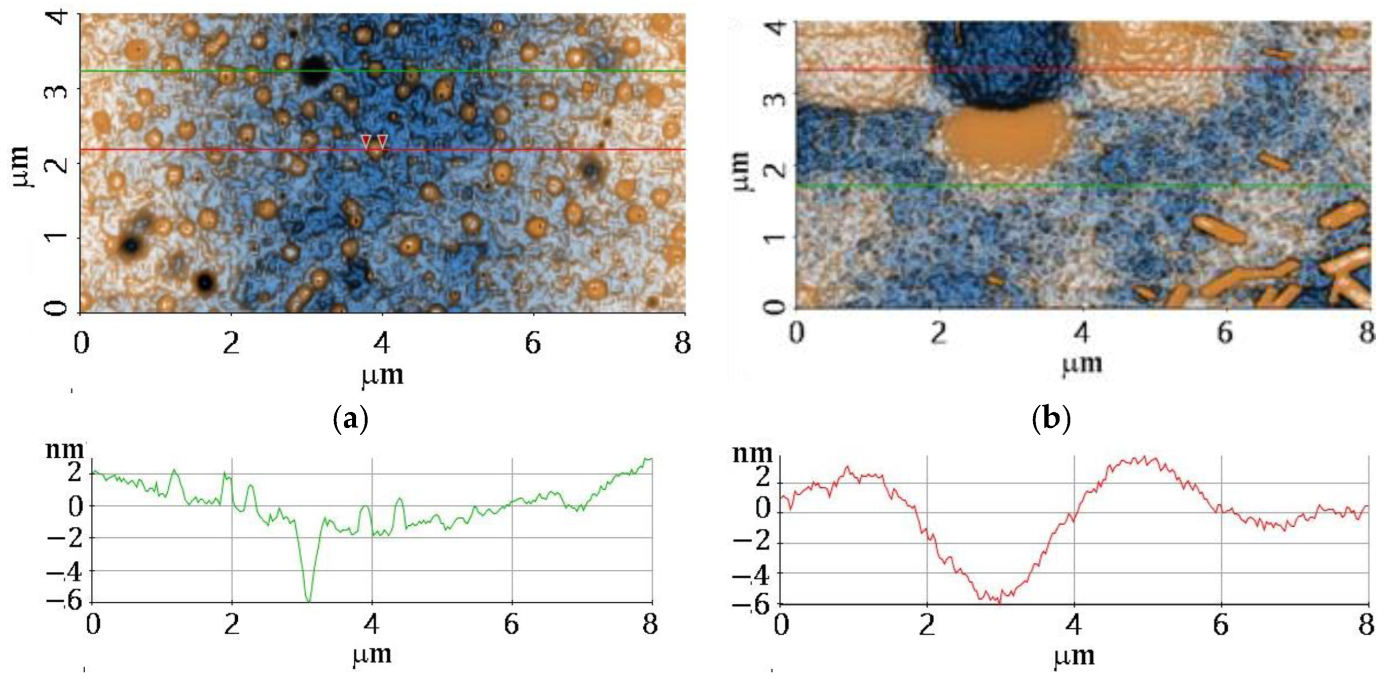
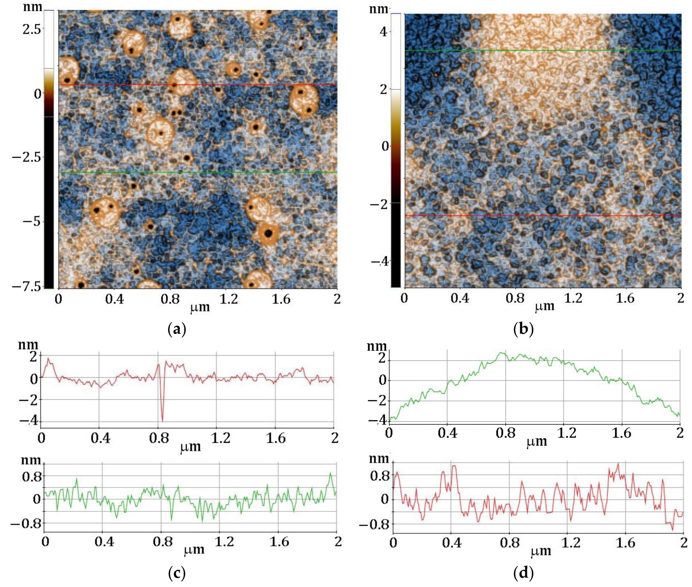
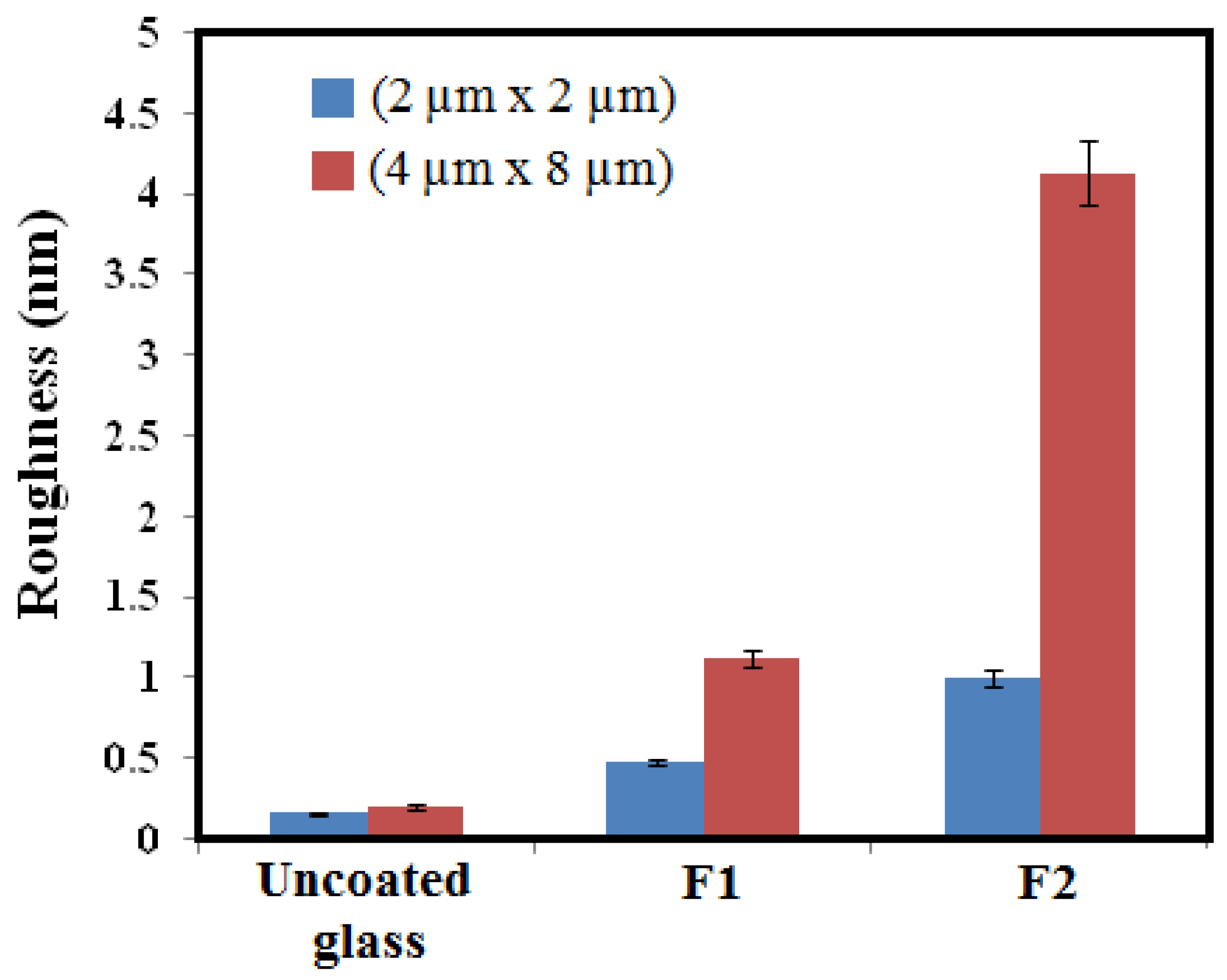
3.4. AFM Analysis
3.5. Optical Analysis
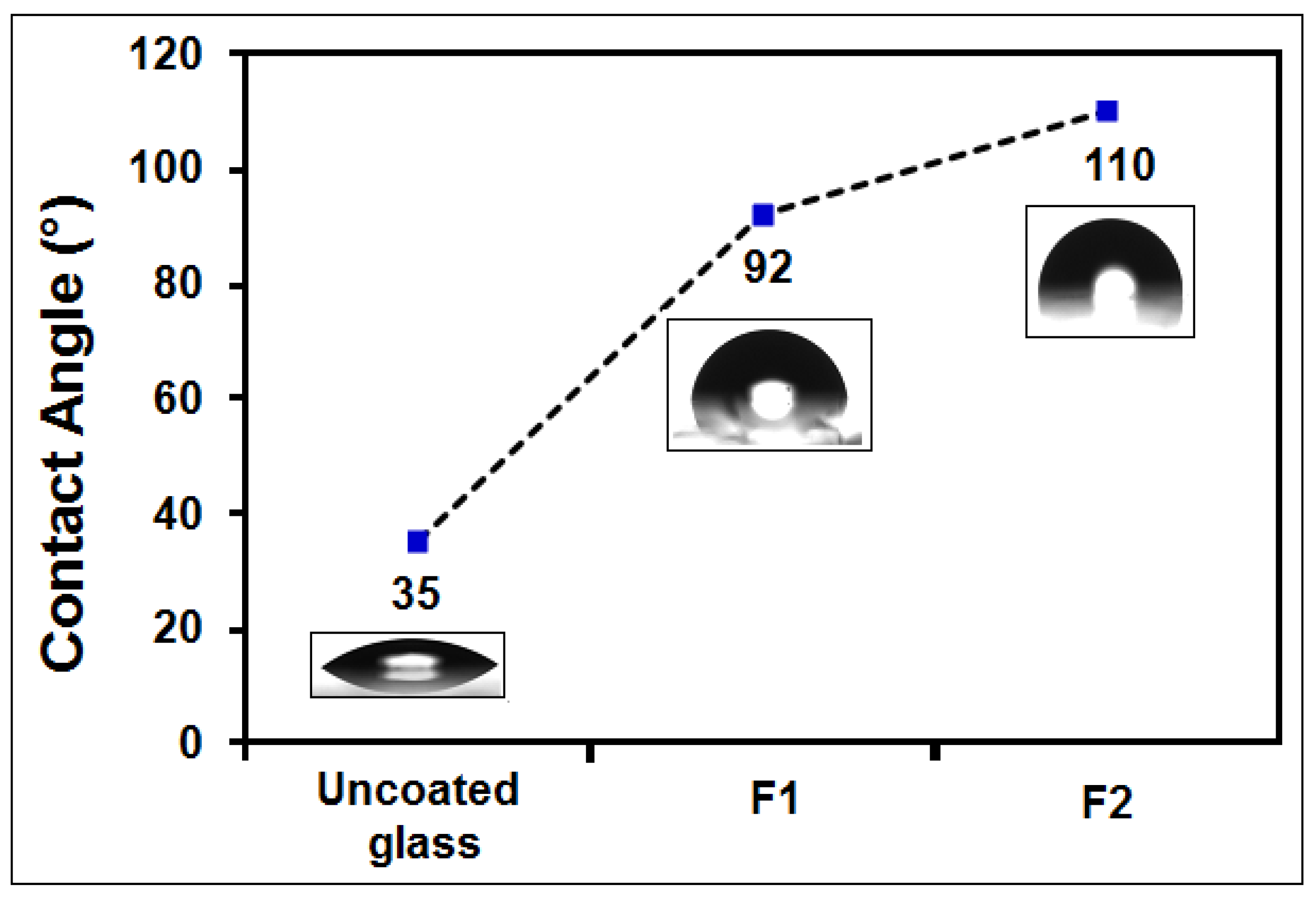
3.6. Contact Angle Measurements
4. Conclusions
Author Contributions
Funding
Institutional Review Board Statement
Informed Consent Statement
Data Availability Statement
Conflicts of Interest
References
- Cardoso, V.F.; Correia, D.M.; Ribeiro, C.; Fernandes, M.M.; Lanceros-Méndez, S. Fluorinated Polymers as Smart Materials for Advanced Biomedical Applications. Polymers 2018, 10, 161. [Google Scholar] [CrossRef] [PubMed] [Green Version]
- Haranahalli, K.; Honda, T.; Ojima, I. Recent progress in the strategic incorporation of fluorine into medicinally active compounds. J. Fluor. Chem. 2019, 217, 29–40. [Google Scholar] [CrossRef]
- Martinelli, C.; Farinola, G.M.; Pinto, V.; Cardone, A. Synthetic Aspects and Electro-Optical Properties of Fluorinated Arylenevinylenes for Luminescence and Photovoltaics. Materials 2013, 6, 1205–1236. [Google Scholar] [CrossRef] [PubMed] [Green Version]
- El-Maiss, J.; Darmanin, T.; Guittard, F. Branched versus linear perfluorocarbon chains in the formation of superhydrophobic electrodeposited films with low bioaccumulative potential. J. Mater. Sci. 2014, 49, 7760–7769. [Google Scholar] [CrossRef]
- Gardiner, J. Fluoropolymers: Origin, Production, and Industrial and Commercial Applications. Aust. J. Chem. 2015, 68, 13–22. [Google Scholar] [CrossRef]
- Iacono, S.T.; Jennings, A.R. Recent Studies on Fluorinated Silica Nanometer-Sized Particles. Nanomaterials 2019, 9, 684. [Google Scholar] [CrossRef] [PubMed] [Green Version]
- Storm, W.L.; Youn, J.; Reighard, K.P.; Worley, B.V.; Lodaya, H.M.; Shin, J.H.; Schoenfisch, M.H. Superhydrophobic nitric oxide-releasing xerogels. Acta Biomater. 2014, 10, 3442–3448. [Google Scholar] [CrossRef]
- Huang, Y.; Yi, S.; Lv, Z.; Huang, C. Facile fabrication of superhydrophobic coatings based on two silica sols. Colloid Polym. Sci. 2016, 294, 1503–1509. [Google Scholar] [CrossRef]
- Ray, S.S.; Lee, H.K.; Huyen, D.T.T.; Park, Y.-I.; Park, H.; Nam, S.-E.; Kim, I.-C.; Kwon, Y.-N. Fluorine-free anti-droplet surface modification by hexadecyltrimethoxysilane-modified silica nanoparticles-coated carbon nanofibers for self-cleaning applications. Prog. Org. Coatings 2021, 153, 106165. [Google Scholar] [CrossRef]
- Oldani, V.; del Negro, R.; Bianchi, C.L.; Suriano, R.; Turri, S.; Pirola, C.; Sacchi, B. Surface properties and anti-fouling assessment of coatings obtained from perfluoropolyethers and ceramic oxides nanopowders deposited on stainless steel. J. Fluor. Chem. 2015, 180, 7–14. [Google Scholar] [CrossRef]
- Jennings, A.R.; Iacono, S.T. Progress in fluorinated organically modified silicas. Polym. Int. 2016, 65, 6–10. [Google Scholar] [CrossRef]
- Fujihara, S. Sol-Gel Processing of Fluoride and Oxyfluoride Materials. In Handbook of Sol-Gel Science and Technology; Klein, L., Aparicio, M., Jitianu, A., Eds.; Springer: Cham, Switzerland, 2018. [Google Scholar] [CrossRef]
- Vilaró, I.; Yagüe, J.L.; Borrós, S. Superhydrophobic Copper Surfaces with Anticorrosion Properties Fabricated by Solventless CVD Methods. ACS Appl. Mater. Interfaces 2017, 9, 1057–1065. [Google Scholar] [CrossRef] [PubMed]
- Dobrzański, L.A.; Gołombek, K.; Lukaszkowicz, K. Physical Vapor Deposition in Manufacturing. In Handbook of Manufacturing Engineering and Technology; Nee, A., Ed.; Springer: London, UK, 2013. [Google Scholar] [CrossRef]
- Vasconcelos, H.C. Optical Waveguides Based on Sol-Gel Coatings. In Electromagnetic Propagation and Waveguides in Photonics and Microwave Engineering; Steglich, P., Ed.; IntechOpen: London, UK, 2020; pp. 1–18. [Google Scholar] [CrossRef] [Green Version]
- Raimondo, M.; Veronesi, F.; Boveri, G.; Guarini, G.; Motta, A.; Zanoni, R. Superhydrophobic properties induced by sol-gel routes on copper surfaces. Appl. Surf. Sci. 2017, 422, 1022–1029. [Google Scholar] [CrossRef]
- Li, Y.; Men, X.; Zhu, X.; Ge, B.; Chu, F.; Zhang, Z. One-step spraying to fabricate nonfluorinated superhydrophobic coatings with high transparency. J. Mater. Sci. 2016, 51, 2411–2419. [Google Scholar] [CrossRef]
- Navas, D.; Fuentes, S.; Castro-Alvarez, A.; Chavez-Angel, E. Review on Sol-Gel Synthesis of Perovskite and Oxide Nanomaterials. Gels 2021, 7, 275. [Google Scholar] [CrossRef] [PubMed]
- Bokov, D.; Jalil, A.T.; Chupradit, S.; Suksatan, W.; Ansari, M.J.; Shewael, I.H.; Valiev, G.H.; Kianfar, E. Nanomaterial by Sol-Gel Method: Synthesis and Application. Adv. Mater. Sci. Eng. 2021, 2021, 5102014. [Google Scholar] [CrossRef]
- Seck, S.; Magana, S.; Prébé, A.; Niepceron, F.; Bounor-Legaré, V.; Bigarré, J.; Buvat, P.; Gérard, J. PVDF-HFP/silica-SH nanocomposite synthesis for PEMFC membranes through simultaneous one-step sol–gel reaction and reactive extrusion. Mater. Chem. Phys. 2015, 163, 54–62. [Google Scholar] [CrossRef]
- Velikova, N.; Spassova, I. Bifunctional mesoporous hybrid sol-gel prepared silicas for CO2 adsorption. J. Sol-Gel Sci. Technol. 2021, 100, 326–340. [Google Scholar] [CrossRef]
- Wan, H.; Mills, R.; Qu, K.; Hower, J.C.; Mottaleb, M.A.; Bhattacharyya, D.; Xu, Z. Rapid removal of PFOA and PFOS via modified industrial solid waste: Mechanisms and influences of water matrices. Chem. Eng. J. 2022, 433, 133271. [Google Scholar] [CrossRef]
- Guo, C.; Ding, H.; Xie, M.; Zhang, H.; Hong, X.; Sun, L.; Ding, F. Multifunctional superamphiphobic fluorinated silica with a core-shell structure for anti-fouling and anti-corrosion applications. Colloids Surf. A Physicochem. Eng. Asp. 2021, 615, 126155. [Google Scholar] [CrossRef]
- Yu, F.; Gao, J.; Liu, C.; Chen, Y.; Zhong, G.; Hodges, C.; Chen, M.; Zhang, H. Preparation and UV aging of nano-SiO2/fluorinated polyacrylate polyurethane hydrophobic composite coating. Prog. Org. Coatings 2020, 141, 105556. [Google Scholar] [CrossRef]
- Startek, K.; Arabasz, S.; Bachmatiuk, A.; Lukowiak, A. Influence of fluoroalkyl chains on structural, morphological, and optical properties of silica-based coatings on flexible substrate. Opt. Mater. 2021, 121, 111524. [Google Scholar] [CrossRef]
- Banerjee, D.A.; Kessman, A.J.; Cairns, D.R.; Sierros, K.A. Tribology of silica nanoparticle-reinforced, hydrophobic sol–gel composite coatings. Surf. Coatings Technol. 2014, 260, 214–219. [Google Scholar] [CrossRef] [Green Version]
- Li, Q.; Yan, Y.; Yu, M.; Song, B.; Shi, S.; Gong, Y. Synthesis of polymeric fluorinated sol–gel precursor for fabrication of superhydrophobic coating. Appl. Surf. Sci. 2016, 367, 101–108. [Google Scholar] [CrossRef]
- Huang, C.-M.; Wang, H.-Y.; Fang, S.-Y.; Yang, W.-D. Influence of Fluorine-Containing Monomer Content on the Hydrophobic and Transparent Properties of Nanohybrid Silica Polyacrylate Coating Materials. Materials 2021, 14, 4261. [Google Scholar] [CrossRef]
- Nimittrakoolchai, O.-U.; Supothina, S. Preparation of stable ultrahydrophobic and superoleophobic silica-based coating. J. Nanosci. Nanotechnol. 2012, 12, 4962–4968. [Google Scholar] [CrossRef]
- Shao, J.; Zhao, Y.; Li, D.; Xu, S.; Dou, Z.; Sun, Z.; Cao, M.; Fu, K.; Liu, Y.; Zhou, Y. Synthesis and characterization of superhydrophobic fluorinated mesoporous silica for oil/water separation. Microporous Mesoporous Mater. 2022, 344, 112240. [Google Scholar] [CrossRef]
- El Fouhaili, B.; Ibrahim, A.; Dietlin, C.; Chemtob, A.; Allonas, X.; Croutxé-Barghorn, C. Single-step formation of superhydrophobic surfaces using photobase-catalyzed sol-gel process. Prog. Org. Coatings 2019, 137, 105293. [Google Scholar] [CrossRef]
- Saboori, R.; Azin, R.; Osfouri, S.; Sabbaghi, S.; Bahramian, A. Synthesis of fluorine- doped silica-coating by fluorosilane nanofluid to ultrahydrophobic and ultraoleophobic surface. Mater. Res. Express 2017, 4, 105010. [Google Scholar] [CrossRef]
- Li, K.-M.; Jiang, J.-G.; Tian, S.-C.; Chen, X.-J.; Yan, F. Influence of Silica Types on Synthesis and Performance of Amine–Silica Hybrid Materials Used for CO2 Capture. J. Phys. Chem. C 2014, 118, 2454–2462. [Google Scholar] [CrossRef]
- Waseem, M.; Mustafa, S.; Naeem, A.; Shah, K.H.; Shah, I.; Ihsan-ul-Haque. Synthesis and characterization of silica by sol-gel method. J. Pak. Mater. Soc. 2009, 3, 19–21. Available online: https://www.researchgate.net/publication/285105909 (accessed on 10 November 2022).
- Cai, S.; Zhang, Y.L.; Zhang, H.L.; Yan, H.W.; Lv, H.B.; Jiang, B. Sol–Gel Preparation of Hydrophobic Silica Antireflective Coatings with Low Refractive Index by Base/Acid Two-Step Catalysis. ACS Appl. Mater. Interfaces 2014, 6, 11470–11475. [Google Scholar] [CrossRef]
- Yu, Q.; Xu, J. Structure and surface properties of fluorinated organic–inorganic hybrid films. J. Sol-Gel Sci. Technol. 2012, 61, 243–248. [Google Scholar] [CrossRef]
- Wagh, P.B.; Kumar, R.; Patel, R.P.; Singh, I.K.; Ingale, S.V.; Gupta, S.C.; Mahadik, D.B.; Venkateswara Rao, A. Hydrophobicity measurement studies of silica aerogels using ftir spectroscopy, weight difference method, contact angle method and k-f titration method. J. Chem. Bio. Phys. Sci. Sec. A 2015, 5, 2350–2359. [Google Scholar]
- Ni, H.; Wang, X.; Zhang, W.; Wang, X.; Shen, Z. Stable hydrophobic surfaces created by self-assembly of poly(methyl methacrylate) end-capped with 2-perfluorooctylethyl methacrylate units. Surf. Sci. 2007, 601, 3632–3639. [Google Scholar] [CrossRef]
- Yao, L.; Yang, T.; Cheng, S. Synthesis and characterization of poly(fluorinated acrylate)/silica hybrid nanocomposites. J. Appl. Polym. Sci. 2010, 115, 3500–3507. [Google Scholar] [CrossRef]
- Fang, C.; Huang, X.; Ge, T.; Li, Y.; Cao, Y.; Zhu, X.; Dong, X. Effect of dodecafluoroheptyl methacrylate (DFMA) on the comprehensive properties of acrylate emulsion pressure sensitive adhesives. Int. J. Adhes. Adhes. 2020, 101, 102634. [Google Scholar] [CrossRef]
- Spataru, C.I.; Purcar, V.; Ghiurea, M.; Radovici, C.; Stanga, G.; Donescu, D. Effects of the nanoassociation of hexadecyltrimethoxysilane precursors on the sol–gel process. J. Sol-Gel Sci. Technol. 2013, 65, 344–352. [Google Scholar] [CrossRef]
- Petcu, C.; Purcar, V.; Ianchiş, R.; Spătaru, C.-I.; Ghiurea, M.; Nicolae, C.A.; Stroescu, H.; Atanase, L.-I.; Frone, A.N.; Trică, B.; et al. Synthesis and characterization of polymer-silica hybrid latexes and sol-gel-derived films. Appl. Surf. Sci. 2016, 389, 666–672. [Google Scholar] [CrossRef]
- Zhou, G.; Simerly, T.; Golovko, L.; Tychinin, I.; Trachevsky, V.; Gomza, Y.; Vasiliev, A. Highly functionalized bridged silsesquioxanes. J. Sol-Gel Sci. Technol. 2012, 62, 470–482. [Google Scholar] [CrossRef]
- Campostrini, R.; Ischia, M.; Carturan, G.; Gialanella, S.; Armelao, L. Rh Inclusion in Sol-Gel SiO2. Effects of Rh Precursors on Metal Dispersion and SiO2-Rh Thermal Behavior. J. Sol-Gel Sci. Technol. 2000, 18, 61–76. [Google Scholar] [CrossRef]
- da Silva, D.G.; Costa, V.C.; Nunes, R.A.X. Preparation of Antireflective Silica Coating by the Sol-Gel Method for Heliothermic Power Plants. Mater. Res. 2018, 21, e20170970. [Google Scholar] [CrossRef] [Green Version]
- Huang, X.; Liao, W.; Ye, L.; Zhang, N.; Lan, S.; Fan, H.; Qu, J. Fabrication of hydrophobic composite films by sol-gel process between POSS -containing fluorinated polyacrylate latexes and colloidal silica particles. Microporous Mesoporous Mater. 2017, 243, 311–318. [Google Scholar] [CrossRef]
- Tadjarodi, A.; Haghverdi, M.; Mohammadi, V.; Rajabi, M. Synthesis and characterization of hydrophobic silica aerogel by two 411 step (acid-base) sol-gel process. J. Nanostruct. 2013, 3, 181–189. [Google Scholar] [CrossRef]
- Tao, C.; Yan, H.; Yuan, X.; Yin, Q.; Zhu, J.; Ni, W.; Yan, L.; Zhang, L. Sol-gel based antireflective coatings with superhydrophobicity and exceptionally low refractive indices built from trimethylsilanized hollow silica nanoparticles. Colloids Surf. A Physicochem. Eng. Asp. 2016, 509, 307–313. [Google Scholar] [CrossRef]
- Capeletti, B.L.; Zimnoch, J.H. Fourier Transform Infrared and Raman Characterization of Silica-Based Materials. In Applications of 416 Molecular Spectroscopy to Current Research in the Chemical and Biological Sciences; Mark, T.S., Ed.; IntechOpen: London, UK, 2016; pp. 1–21. [Google Scholar]
- El-Denglawey, A.; Makhlouf, M.; Dongol, M. The effect of thickness on the structural and optical properties of nano Ge-Te-Cu films. Results Phys. 2018, 10, 714–720. [Google Scholar] [CrossRef]
- Borkar, S.; Jankova, K.; Siesler, H.W.; Hvilsted, S. New Highly Fluorinated Styrene-Based Materials with Low Surface Energy Prepared by ATRP. Macromolecules 2004, 37, 788–794. [Google Scholar] [CrossRef]
- Zhang, Q.; Zhan, X.; Chen, F.; Shi, Y.; Wang, Q. Block copolymers of dodecafluoroheptyl methacrylate and butyl methacrylate by RAFT miniemulsion polymerization. J. Polym. Sci. Part A Polym. Chem. 2007, 45, 1585–1594. [Google Scholar] [CrossRef]
- Brassard, J.-D.; Sarkar, D.K.; Perron, J. Synthesis of Monodisperse Fluorinated Silica Nanoparticles and Their Superhydrophobic Thin Films. ACS Appl. Mater. Interfaces 2011, 3, 3583–3588. [Google Scholar] [CrossRef]


| Sample | 30–100 °C | 100–240 °C | 240–750 °C | Residue at 750 °C | ||
|---|---|---|---|---|---|---|
| Wt. Loss % | Wt. Loss % | Tmax 1 °C | Wt. Loss % | Tmax °C | N2 % | |
| F1 | 3.64 | 7.94 | 131.6 | 4.04 | 470.7 | 84.37 |
| F2 | 1.38 | 2.59 | 114.1 | 27.31 | 518.8 | 68.72 |
| Sample | dfilm (nm) | Roughness (nm) | MSE |
|---|---|---|---|
| F1 | 1052 | 0.93 | 1.804 |
| F2 | 1570 | 2.34 | 1.468 |
Disclaimer/Publisher’s Note: The statements, opinions and data contained in all publications are solely those of the individual author(s) and contributor(s) and not of MDPI and/or the editor(s). MDPI and/or the editor(s) disclaim responsibility for any injury to people or property resulting from any ideas, methods, instructions or products referred to in the content. |
© 2023 by the authors. Licensee MDPI, Basel, Switzerland. This article is an open access article distributed under the terms and conditions of the Creative Commons Attribution (CC BY) license (https://creativecommons.org/licenses/by/4.0/).
Share and Cite
Purcar, V.; Rădiţoiu, V.; Raduly, F.M.; Rădiţoiu, A.; Căprărescu, S.; Frone, A.N.; Şomoghi, R.; Anastasescu, M.; Stroescu, H.; Nicolae, C.-A. Influence of Perfluorooctanoic Acid on Structural, Morphological, and Optical Properties of Hybrid Silica Coatings on Glass Substrates. Appl. Sci. 2023, 13, 1669. https://doi.org/10.3390/app13031669
Purcar V, Rădiţoiu V, Raduly FM, Rădiţoiu A, Căprărescu S, Frone AN, Şomoghi R, Anastasescu M, Stroescu H, Nicolae C-A. Influence of Perfluorooctanoic Acid on Structural, Morphological, and Optical Properties of Hybrid Silica Coatings on Glass Substrates. Applied Sciences. 2023; 13(3):1669. https://doi.org/10.3390/app13031669
Chicago/Turabian StylePurcar, Violeta, Valentin Rădiţoiu, Florentina Monica Raduly, Alina Rădiţoiu, Simona Căprărescu, Adriana Nicoleta Frone, Raluca Şomoghi, Mihai Anastasescu, Hermine Stroescu, and Cristian-Andi Nicolae. 2023. "Influence of Perfluorooctanoic Acid on Structural, Morphological, and Optical Properties of Hybrid Silica Coatings on Glass Substrates" Applied Sciences 13, no. 3: 1669. https://doi.org/10.3390/app13031669