1. Introduction
The first harmonic drive was patented by Clarence Walton Musser in 1959 [
1]. Since then, many new constructions have been created and new ones, differing in construction and purpose, are constantly appearing [
2,
3,
4]. Harmonic drives have a wide range of applications in robotics, control and regulation systems, and measuring devices [
5,
6,
7]. However, the harmonic drives used so far in space vehicles are constructed with a flexspline having a classical shape of a sleeve or cup. In these constructions, there are problems with lubrication due to oil contamination or loss. Therefore, the important aspect is adequate sealing of the gears. Along with the dynamic development of aviation and the space industry, they are also increasingly used there [
8,
9,
10]. The harmonic drives are applied to construction demanding drives with high efficiency, a high gear ratio, and compact dimensions [
11,
12,
13]. A particularly important advantage of harmonic drives is high kinematic accuracy. It can be provided by a correct choice of the geometry of gear components, but also by using adequate materials. The high precision in these types of drives is due to the unique construction and character of these drives. The classical harmonic drive consists of the flexspline, the circular spline, and the generator. Each of the three basis parts can be a driving or driven element. The harmonic drive can work as a reductor, multiplicator, or differential gear.
Figure 1 presents a schematic diagram of the hermetic harmonic drive.
The characteristic feature of the harmonic drive is a way of transferring motion to the passive element (2) as a result of the cycle deformation of the flexspline (1) by the wave generator (3). The flexspline, while the harmonic drive is working, is deformed by the generator in the radial direction by its relative rotational motion. The flexspline has an outer toothed wheel rim with which the internally toothed circular spline meshes. The number of flexspline teeth is lower than the number of circular spline teeth; hence, outside the meshing area, the teeth of both circulars pass each other. These harmonic drives can have generators with different shapes, methods of operation, and numbers of waves of deformation on the circuit of flexspline, which also influences its complexity. A large number of construction solutions are also in operation. New types of harmonic drives are still being researched, and they have applications in new, previously unprecedented areas of life. Often, the emergence of new design solutions is related to the requirements and expectations of the environment. The need for harmonic drive-in isolation from the space of the engine forced an uprising for a new type of harmonic drive-in—the hermetic variant. The hermetic harmonic drive has this unique feature that allows handover to an insulated space separated from the ambient by a partition. Moreover, it is the possible opposite solution, in which the engine is closed in a sealed casing and torque is passed to the outer just by hermetic harmonic drive.
The applied type of generator can directly impact the form of flexspline and the kinematic accuracy of the entire drive. The selection of the appropriate type of generator is not simple because access is not always available to special gears or advanced technology that allows cam machining. In the article, there was also the possibility of the execution of the elements of harmonic drive by using incremental methods such as 3D printing. This possibility is analyzed for the production and reproduction of elements of harmonic drive in outer space. These harmonic drives, thanks to high kinematic accuracy, can be used in control systems of transmitting antennas or in the drives of vehicles on colonized planets. Hence, it is essential to have knowledge of the accuracy of harmonic drives in terms of the applied type of generator. Depending on the available execution options, the type of wave generator affects the kinematic accuracy of the wave gear available under given conditions. In harmonic drives, it is essential to ensure the hermetic is possible by application flexspline about a specific construction.
The flexspline is a long gear with the shape of a thin-walled sleeve with a toothed rim in the middle. On one side, it is finished with a flange for fastening to the partition and, on the other, with a bottom that separates the hermetic space from the ambient space (
Figure 2). The flexspline construction results in many complex loads and deformations during work. It is the most loaded element of hermetic harmonic drive, and it is especially exposed to different kinds of damage through its thin-walled construction. As a result of the influence of the wave generator and torsional stresses derived from the torque, the flexspline bending stresses occur.
In the existing literature on construction and technological solutions and the research on harmonic drives, there are very few works that present their hermetic type. Existing publications presented only general attributes of these harmonic drives and did not solve the important problems in terms of strength and durability [
14,
15,
16,
17]. The largest number of publications on hermetic wave gears comes from the second half of the previous century due to the dynamic development of the space industry, research flights, and the landing and exploration of Earth’s moon at that time. The studies on harmonic drives published at this time were published by many Russian researchers [
18,
19,
20] and their competitors cooperating with NASA [
8,
21]. In view of the results and conclusions from the calculations included in these works, these publications were not satisfied with the present expectations of and perspectives on the use of hermetic harmonic drives. Additional contemporary studies [
22,
23,
24] discussed the geometry but did not raise the strength and kinematic problems of these gears. The most extensive discussion of the hermetic type of harmonic drives was included in the monograph [
25], which describes their application to precise vacuum mechanisms. All the mentioned publications show the flexspline as a thin-walled sleeve of different shapes in the longitudinal section, starting from completely cylindrical through conical to curvilinear with large rounding radii. There are also propositions to combine two sleeves of different diameters to shorten the overall length of the flexspline. None of the constructions of the hermetic harmonic drive presented in the above-mentioned publications has been subjected to detailed strength and durability analysis. The most probable result is that such complicated calculations exceeded the technical possibilities of computers of the time. The computational works in this area were done only by the authors that rejected most of the proposed flexspline shapes as inadvisable due to the risk of cracking [
26,
27,
28]. In view of the complicated shape of the flexible sleeves, the authors also performed the analysis of the flexspline with a welded bottom, which can make it easier to make it out of steel. Due to the perspective of the use of harmonics drives and their production by incremental methods in outer space, the authors also carried out research in this area [
29,
30]. In addition to the work of the authors [
29,
31], there are no studies considering the kinematic accuracy of hermetic harmonic drives. High kinematic accuracy is required especially in vehicles and devices working in outer space, where even the smaller setting error adversely affects changes in flying trajectory or settings of communication antennas. In view of the vacuum in space, the desired feature of devices that work is also their hermetic. Harmonic drives have been used for years in manipulators and wheel drives of space vehicles moving on the surface of Mars. In these cases, the tightness of the construction allows for securing the sensitive toothed wheel rim or elastic bearing from damaging dust and mechanical impurities. The combination of these exceptional features, i.e., kinematic accuracy and tightness, makes it so that the hermetic harmonic drive could be used in steering and regulating mechanisms used in an unfavorable environment (for example, outside the Earth’s atmosphere).
2. Impact of Type of Generator on Flexspline Deformation Form
The correct work of the harmonic drive is possible by an adequate deformation of the flexspline by the wave generator. The neutral layer of the flexspline body under the toothing can take various forms of curvature, depending on the wave generator used. The obtained character of deformation is chosen based on the correctness of the toothing of circles and their influence on the quality of work of the harmonic drive. Therefore, it is important to choose the appropriate type of wave generator, which for the chosen harmonic drive allows obtaining the highest kinematic accuracy. There are generators, hydraulic, pneumatic, and electromagnetic options, but due to their simple structure and easy operation, mechanical generators are used most often [
23,
32]. The generator can cause a different number of waves which allows one to determine them as single-wave, double-wave, or three-wave. The most often used are double-wave generators because additional waves on the circumferences of the flexspline make a significant increase in bending stresses in its body [
33,
34].
Among mechanical generators, there are four main types shown in
Figure 3, which are different in construction and operation principles. There are generators: two-roll, four-roll, disc, and cam generators. Using all listed types entails the determined benefits and limitations, and using them depends on the destination of the drive and the technology possibilities that make the type of generator.
Roller generators in double-wave harmonic drives have a combined slider of two or four rolls, with the deformation of the toothed wheel rim of the flexspline to the form of a thin-walled ring loaded with two or four forces, respectively (
Figure 3a,b). In a two-roll generator, the rolls face opposite one another and forces operate in the large axis of the generator. In the four-roll generator, the rolls are facing at an angle γ (
Figure 3b) from its large axis, whereas the deformation forces of the neutral layer of the flexspline work at an angle γ, which generally has a value within the limit of γ = 25 ÷ 35° [
34].
The outer diameter of the generator roll
Dr = 2
Rr should be possibly as large as
Dr = (0.25 ÷ 0.3)
d1 (where:
d1—pitch diameter of the flexspline). The advantage of roll generators is simple construction and the possibility of using them for anything, obtained from the calculation and the inner diameters of the flexspline. It allows us to obtain strictly calculated gear ratio values and makes it easier to select the parameters of the toothed rings and other dimensions of flexsplines. The disadvantage of this type of generator is the limited possibility of using them for large rotational speeds of generators and the impossibility of keeping a complex form of the toothed ring of flexspline after the loading of the harmonic drive by torque. The disc generator has the name of the disc installed on the eccentrics, which is deforming a flexspline. The two-wave generators of the harmonic drive have the discs shifted to each other at an angle of 180°. Disc diameters are bigger than rolls in roller generators; therefore, the disc generator makes it possible to maintain the computational form of deformation of the neutral layer of the flexspline, even under the load of the harmonic drive. Its disadvantage is that the disc of the generator does not support the toothed ring across its full width, allowing additionality stresses to occur. In designing a wave generator, it is necessary to designate the generator angle
2γ of which the disc comes into contact with the flexspline and radius R
t of the generator disc. Due to the most favorable stress distribution, it is recommended to use the angle value γ = 20 ÷ 40° [
22].
Currently, the most commonly used harmonic drives are cam generators. Their characteristic element is the elastic bearing, which is placed in the corpus of the cam-shaped generator. The elastic bearings used in these generators are special with thinner rings and separators centered by rolling elements. The cam deforms the bearing, giving its ring shape and allowing the form of deformation of the neutral layer of the flexspline to be required. The cam generator can deform the flexspline into any form of deformation described by the equation at the assumed, unchanged value of the cam circumference [
34]. The bearing of the cam generator adheres to the inner surface of the flexspline, allowing its deformation to form all over the perimeter; hence, there are no additional deformations of the toothed ring after loading the harmonic drive with torque. The neutral layer of the flexspline is deformed cyclically during operation and takes the appropriate shape for the type of generator used.
Figure 4 shows the momentary displacement of segment
A0B0 of the neutral layer of the corpus of flexspline before the deformation position of
A2B2 and after its deformation by the generator. The occurring radial displacement
w, the circumferential displacements
v, and rotation angle
θ of the normal for the neutral layer of flexspline depend on angle
φ measured from the major axis of the generator.
The segment
A0B0 of the undeformed neutral layer of the flexspline corpus, after its deformation with a generator, moves to position
A2B2. At this time, the normal point
A0 will rotate about angle
θ, which is the difference between the angles
θ1 and
θ2 (
Figure 4). The radial and circumferential displacements and rotation angle of the normal in point
A of the neutral layer allow its location to be determined in relation to the flexspline origin of the polar coordinate system. Because the impact of different generators on the neutral layer of the flexspline is different, the forms of deformation for different types of generators are different, and therefore their respective displacements differ from each other. Analytical calculations contain geometric simplifications and ignore the impact of the load on the torque, resulting in additional deformation of the neutral layer. In these calculations, the toothed ring is replaced by the smooth ring and the influence of the flexspline body sleeve is ignored. Equations allowing for the calculation of geometric parameters of the neutral layer of flexspline for different types of generators are available in many publications [
12,
14,
17] and will not be discussed in more detail because the analysis used more advanced computational tools. During the operation of the harmonic drive, the wave generator rotates, causing the mating of successive pairs of teeth of both gears. Each of the teeth of the flexspline moves from one interdental notch to the next with the circular spline. On the major axis of the flexspline, the teeth are fully in mating, while in the minor axis of the generator, the teeth of the two gears pass each other, as shown in
Figure 5.
Point
A on the tip of the flexspline teeth determines a trajectory with a shape depending on the type of generator, parameters of the rim of the toothed wheel rim, and which of the gears is stationary. Determining the relative path of the teeth takes place in the
y,
z coordinate system associated with a fixed circular spine. In the situation described above, the beginning of this system (0) is at the intersection of the undeformed layer of the flexspline with radius
R with a minor axis of the generator. To define the location unambiguously, the tooth in this coordinate system should be determined by the position of its two characteristic points. In an undistorted flexspline, these points are
A0—at the intersection of the tooth axis with the tip circle and
F0—at the intersection of the tooth axis with the root circle. The coordinates of the points
A2 and
F2 of the teeth of the circular spine in the
y,
z coordinates system on the
z-axis are presented in Formulas (1) and (2) [
22,
35,
36]:
The coordinates of
va2 and
vf2 are equal zero because these points laying on
z axis (3) and (4):
The position of the tooth of flexspline in the
y,
z coordinate system is variable and depends on the angle
φ of the generator rotation. At the initial moment
t = 0, the major axis of the generator is parallel to
y-axis, and after time
t > 0 will turn about angle
ωgt. The current location of the major axis of the generator relative to the starting position is determined by angle
φ (5) [
22,
34,
35]:
where:
ωg—angular velocity of the wave generator,
t—time.
Depending on the position of the major axis of the generator, the angle of the rotation of flexspline
φ2 has values according to the dependency [
22]:
where:
i—gear ratio.
The coordinates of the points
A1 and
F1 of the adequate flexspline tooth on the
z-axis (
wa1,
wf1) and on the
y-axis (
va1,
vf1) are the same as in Formulas (7)–(10) [
22,
34,
35]:
where:
θ—the angle of rotation of the normal exposure to the neutral layer of the flexspline by angle
φ,
w—radial displacement of the neutral layer point of flexspline,
v—circumferential displacement of the neutral layer point of the flexspline.
Figure 6 shows the trajectory of the
A1 point of a single tooth lying on the intersection of the axis of symmetry with the tip radius of the flexspline. The displacement of this point is determined in the coordinate system
y,
z and combined with a fixed circular spline and calculated based on dependences (7) and (9) for the values of the rotation angle of generator in range 0 ≤
φ ≤
Π/
2.
In the flexspline initial moment (
φ = 0°), the tooth enters maximally in the space of the circular spline. If that occurs, then the full penetration
hw is predicted for the harmonic drive. As a result of the rotation of the generator at angle
φ, the teeth of the flexspline will start to move, and its characteristic point A
1 will move along the trajectory shown in
Figure 6. When the generator rotates at an angle (
φ = 90°), the teeth of the flexspline will come out of the mesh and position themselves opposite the teeth of circular spline A′
1. In the right-designed harmonic drive, the moving teeth of the flexspline should bypass the teeth of the circular spline so that there is no interference.
This complicated character of the work of harmonic drive causes many construction, material, technology, and exploitation problems. Thus, because of the smooth meshing of successive teeth, harmonic drives are characterized by high smoothness of work and kinematic accuracy. The quality of the gear operation also influences the flexspline form of deformation of the neural layer obtained by the application of different types of generators. The harmonic drives of general applications used in the machine tool industry, robotics, or valve control have, for these applications, sufficiently high precision. When there is a need to use the hermetic harmonic drive in spacecraft control systems, the highest kinematic accuracy is expected from them. Therefore, it is important to perform an analysis to determine for which of the mechanical wave generators the angular error of the hermetic harmonic drive is the lowest.
3. Preparation of Numerical Calculations
The issues related to the cooperation of gears in the harmonic drive are complicated and require a large number of operations. If the calculations are made in an analytical method, it is necessary to transform and solve many geometrical dependencies. The results obtained this way, through the simplifications contained therein, do not provide solutions equivalent to the real ones. Also useful are any numerical tools and computer programs that can improve this calculation process. A good universal calculation tool that supports engineering design is the finite element method (FEM). There are a lot of computer programs based on the numerical FEM method, which definitely facilitates calculations concerning harmonic drives. Many of them are integrated with programs for computer-aided design (CAD). Moreover, the possibilities of computer modeling and numerical calculations were used during the preparation and calculation of the hermetic harmonic drive.
The considered issue concerning the influence of the generator type on the kinematic accuracy of the hermetic harmonic drive is a very complicated task. In the numerical calculation, it is necessary to include three cooperating elements of the harmonic drive, namely flexspline, circular spline, and wave generator. Moreover, it is necessary to define the surface of contact between pairs of these elements and their continuous control because conditions of contact are changed at different stages of calculation. The next problem is the elastic deformation of the flexspline, which should be defined correctly. A much more complicated problem is the forced rotation of the circular spline relative to the flexspline. This motion of the circular spline is the result of the deformation of the flexspline by the wave generator with simultaneous rotation of the generator about the axis of the gear. Analysis of the accuracy of the cooperation of gears in the harmonic drive requires a precise definition of the boundary conditions for the rotation of the wave generator.
Numerical analysis FEM using full model hermetic harmonic drives would require large memory operation resources of the working station and would take a very long time. However, for special causes, it is necessary to find the exact way to solve construction tasks. For the vast majority of numerical calculations, it is enough to use only simplified models. The calculation models can be fragments of real components or have changes in geometry to simplify their build. In many analyses, gears can be successfully used with two-dimensional models being their cross sections. Such a simplification is also possible in the case of the analyzed hermetic harmonic drive. The flexspline had a toothed wheel rim in the middle of its length and straight teeth with a constant contour. The dimension of the width of the toothed wheel rim compared to the height and width of a single tooth is large. Moreover, it is necessary to mention that all cross-sections of a single tooth have the same profile and are between non-movable end walls, which are impossible to relocate toward the main axis of the gear. In addition, it was assumed that the load of the circular spline is evenly distributed across the width of the toothed flexspline wheel rim. With such assumptions, each single tooth cross-section is under the same conditions and is equally loaded. If the assumptions presented are met, it can simplify the spatial problem of the wheel rim to the two-dimensional problem in a plane state of strain. Since each cross-section is the same, when carrying out numerical analyses, it is enough to consider only the middle layer of the toothed wheel rim with a unit thickness, i.e., an adequate cross-section of the flexspline passing through the center of the toothed wheel rim. In this way, two-dimensional models for numerical calculation FEM realized in the Abaqus program were made.
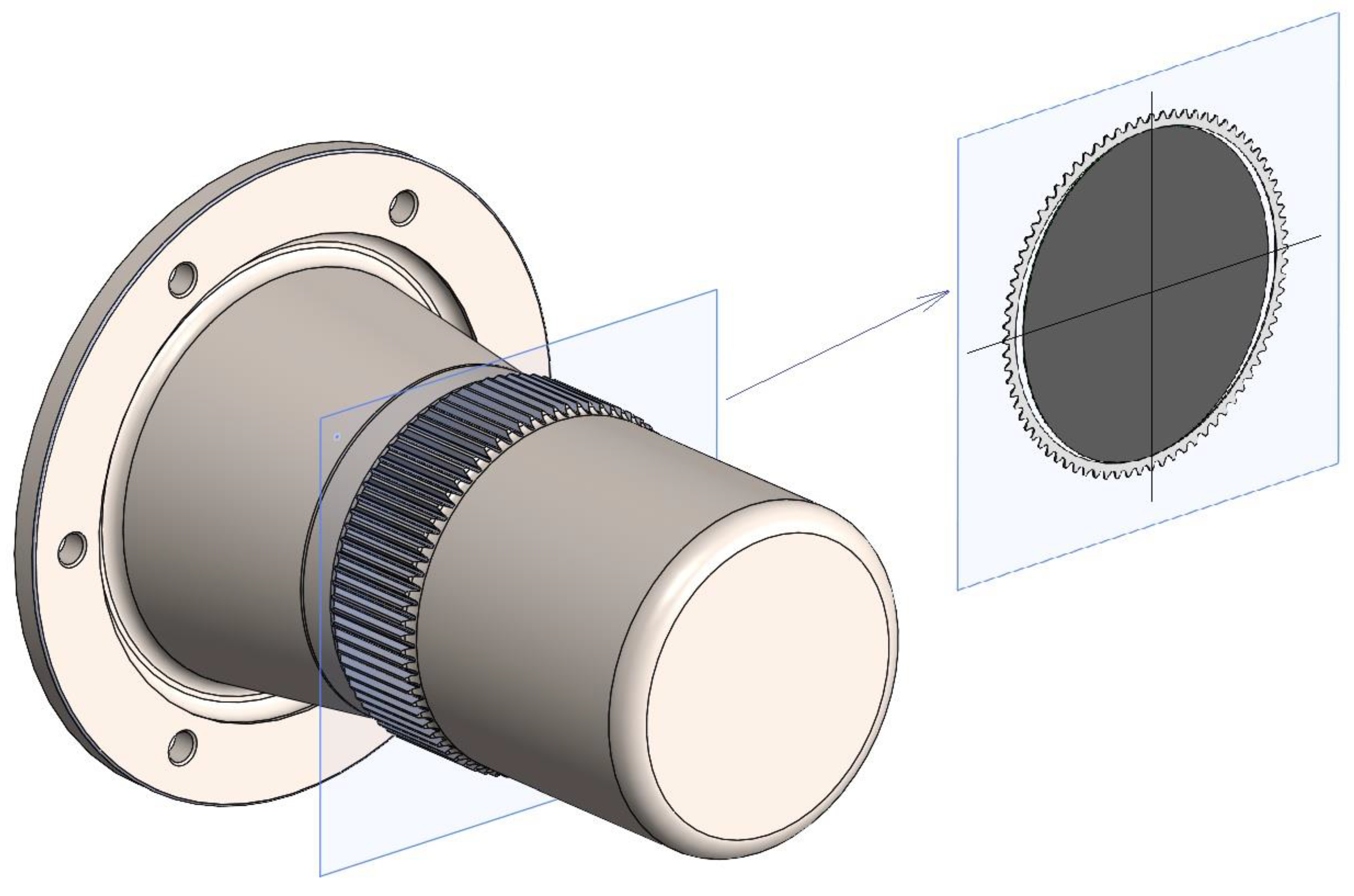
Figure 7 presents an ideological way to create a section of flexspline and generator in a CAD program. To improve the readability of the drawing, the circular spline was omitted, which was included in the calculations.
In the case of the planar theory of elasticity, the two-dimensional models of the full harmonic drive are analyzed, therefore its calculation using the FEM method and the processing of results takes less time. It is caused by a much smaller number of finite elements needed to describe the model, and through it also a smaller number of formulas are necessary to solve the computing program. In view of device limitations, it is sometimes the only possibility for a precise computer analysis of harmonic drives or for confirming the mating of their components.
For the needs of the realized task, the initial project of the hermetic harmonic drive was done by determining its geometric parameters. In addition, check calculations were performed that refer to the interference of the teeth of the mating wheels for each of the four types of generators. Then, on the basis of analytically obtained geometrical parameters, solid models of the main components of the harmonic drive were created. These models were created in the SolidWorks program by defining four assemblies for each of them with the other type of wave generator. On their basis, two-dimensional models were prepared, which are cross sections passing through the middle of the width of the toothed wheel rim of both wheels and the generator. The models prepared in this way were used as a basis for strength calculations using FEM, which were performed in the Abaqus program. A sample model of harmonic drive with a double-roller generator used in the calculations is shown in
Figure 8 and
Figure 9.
In the figure are visible all components of the gear and marks of some boundary conditions introduced during the creation of the computational model. Preparation of numerical calculations of kinematic accuracy started by loading models into the counting program, their settings, and linking them with each other. Then they were discretized using quadrangular finite elements with appropriate mesh density in particularly important areas. The increase in mesh density is defined on the teeth flanks of both gears and on the inner diameter of the flexspline and generator because these surfaces are in contact during operation. Boundary conditions were also defined for all models, as well as displacements and loads, in accordance with the real nature of the operation of the harmonic drive elements. Because the analysis refers to a hermetic harmonic drive in which the flexspline is attached to the casing, in the computational model the possibility of deformation was allowed but the possibility of rotation was blocked. The circular spline and the flexspline were associated with the point positioned on their axis (0) using rigid links. This point was fixed, but the possibility of rotating was allowed to realize the load of the harmonic drive. At this reference point, the angle of rotation of the circular spline was also read after rotating the wave generator about the determined angle φ.
Calculations for each variant difference were only the type of generator used and were composed of three steps. In the initial step, a deformation of the flexspline occurred by a wave generator for the tested model. This stage was not taken in the analysis because it had only caused the wheels to mesh, as it is in a real harmonic drive.
In the first stage, rotation of the wave generator about angle 1 rad in a positive direction was forced, and the load of harmonic drive by torque was realized. In the next stage, rotation of the wave generator was also followed, but in this case in the negative direction of 2 rad. The stages followed each other smoothly and allowed us to trace the relative rotation of the gears forced by the rotation of the generator. It was also possible to determine the backlash of the harmonic hermetic drive when changing the direction of rotation of the generator.
4. Results
The calculations for all four variants were without errors and obtained a lot of result data, allowing us to conduct a thorough analysis of many aspects of the work of the hermetic harmonic drive. The basic results obtained in the Abaqus postprocessor are displayed as stress distribution on the surface of the analyzed model.
The preliminary comparison of them has revealed that discrepancies occur with different types of generators. The distribution of areas with significantly higher values on the flexspline model in the next variant of calculations was also different.
Figure 10 and
Figure 11 show the results obtained for the harmonic hermetic drive with a flexspline deformed double-roller generator without torque.
Areas of increased stress in all calculation variants occurred in areas of the major (D) and minor (M) axis of the generator because the deformation of the flexspline is the highest. However, in none of the computational models were the allowable stresses exceeded. However, a more detailed stress analysis was not performed because the main purpose of the analysis was to determine the kinematic accuracy of the harmonic drive.
The first point of analysis was to compare the angle δ of rotation of the circular spline of the harmonic drive depending on the angle φ of rotation of the generator. In these calculations, rotation of the generator model to angle 1 radian was forced, firstly in the positive destination and then in the negative from the major axis of the generator. The rotation of the wave generator caused the proper rotation of the circular spline, which is the result of the meshing pairs of teeth on both gears. Because the harmonic drive ratio tested was large (i = 95), observation of the models on the computer screen was not allowed for capturing the differences between individual results. For each of the models, there were prepared graphs of the angle of rotating the flexspline, depending on from angle of the rotating generator. In each of them, the nominal value of the angle of rotation of the flexspline has been drawn with a thin grey line. This theoretical value was determined from formulas only on gear ratio. None of the wave generators’ values of the actual angle of rotation of the circular spline do not converge with the nominal values. In the case of both roller generators, in the first phase of cooperation, the rotation of the circular spline is delayed relative to the theoretical value. After rotation about the angle 1 radian, the equalization of the angle value of rotation of the circular spline was obtained in the results of the simulation with the nominal value. Therefore, at this value, the wave generator was stopped and forced to rotate in the opposite direction to a value of −1 radian from the main axis. During the return movement, an even greater delay of the circular spline in relation to the theoretical value was noticed in the analyzed model. The delays occur in the first phase of moving the generator, and then the values of the angle of rotation of the flexspline are approaching theoretically. This shows the high kinematic inertia of the harmonic drive with roller generators. For the other two generators, the course of the graph of the angle of rotation of the circular spline obtained as a result of numerical calculations was much closer to the nominal one. It resulted from the construction of these generators, which allows for the control of form deformation of flexspline much better than roller generators. Of all the computational models, the most favorable course of the graph was obtained for the cam generator, which is in contact with the inner diameter of the flexspline along its entire circumference.
Furthermore, in the case of this type of generator, it was noticed in the numerical simulation that there is a slight delay in the rotation of the circular spline relative to the nominal value. This is the result of clearance occurring between the mating gears, the stiffness of the computational models, or the slide of the generator. At the beginning of cooperation, it also follows the “tooth arrangement” considered with a minimum deflection of the toothed wheel rim to match the flanks of the teeth of both gears. This phenomenon was not described earlier, but it was observed in the results from numerical calculations after applying a sufficiently large scale of deformation during presentation moves and selecting a small range of results (
Figure 12).
The graphs of the angle of rotation of the flexspline relative to the rotation angle of the generator help to indicate characteristic discrepancies relative to theoretical values. They allow one to determine whether there is a deceleration or acceleration relative to the nominal values of the angle of rotation. However, to accurately compare the angular value of the difference for different types of wave generators, additional calculations were made in the spreadsheet, and their result is shown in
Figure 13. In this plot, the graphs of the angle error of the flexspline relative to the nominal values were compiled, which corresponds to the axis of the abscissa (X) in the graph. All fragments of charts obtained in results of numerical calculations FEM for different generators above the axis means acceleration of circular spline relative nominal value, whereas negative values mean delay of the circular spline. The chart can read that the largest temporary angular error occurs for a four-roll generator and is equal to 0.0062247 radians, so 21 arc minutes and similar values are for the two-roll generator.
The slightest error read for the cam generator was 0.003 radians, so about 4 arc minutes. The wave generator recommends that the angular error is kept in the range of 1 to 9 arc minutes [
37]. The kinematic error was also lower for the double-disc generator than for the roller generator and was equal to 0.0041344 radians.
The kinematic error for the roller generators was the highest and exceeded the values even recommended for standard harmonic drives. These two types were omitted in the next part of the analysis. Clearly, gears equipped with roller generators still have high kinematic accuracy and can be used successfully in valve mechanisms and regulators or machine tool setting systems. They definitely have a much simpler construction than cam generators, which in many cases is decided during the choice of these wave generators in the harmonic drive.
Selected models of harmonic drives with double-disc and cam generators were further analyzed. The influence of the load of torque on the kinematic accuracy of the harmonic drive was tested. The same computational models as in the previous calculations were used, but the only difference was that the circular spline was loaded with an additional torque of about 200 Nm. Two variants of the calculation were assumed. In the first, the direction of the torque was consistent with the direction of rotation of the generator (positive) and with the direction of the circular spline. In the second step, the moment (negative) resisted the movement of the wheel because it was opposite to the direction of its rotation.
In the graphs shown in
Figure 14 and
Figure 15, the rotation angle without a load in relation to the rotation angle of the generator was marked by a black color (0). After the circular spline was loaded by torque in accordance with its rotation, there was not a clear difference in the view of the model without load. The graph obtained by numerical calculations for this calculated variant has a green color (2). Almost every time, the charts for these two types of cause overlap. Larger discrepancies occurred in the case of loading the circular spline of torque in the opposite direction. The red-colored figure (2) corresponds to this case. The largest differences are noticeable after crossing a torque angle equal to 1 radian. At this point, the generator stopped and started to rotate in the opposite direction, which also caused the circular spline to rotate in the opposite direction. Differences in the chart regarding the reversing and return movement of the generator indicate for both types of generators the largest differences from the no-load solution. However, the waveform of the graph for the return rotation (from 1 to a −1 rad) refers to the model with a load opposite to the direct torque of the wave generator that is mostly parallel to the case without load. Based on this, it can be assumed that the kinematic error occurs during the change of directions of the rotating generator. Since during further cooperation the deceleration of the circular spline did not increase, it was a consequence of the backlash of the cooperating teeth of both gears and the deformation of the flexspline.
In the presented charts concerning hermetic harmonic drive with the do generator differences and cam generator, we can notice both the shape of the graph and the error values. The harmonic drive with a cam generator should be rated as more accurate, also in the case of its load with torque. It can be concluded that the load of the hermetic harmonic drive had a significant impact on its kinematic accuracy. This factor can have little importance by using harmonic drives in space vehicles where gravitation is low, so a large part of the load can be omitted at a low level. It is also worth paying attention to the direction of the load of flexspline by outer torque because this factor influences accuracy in reverse motion.
Harmonic drives are used in the control mechanisms of antennas or manipulators of space vehicles where there is a continuous change in the direction of rotation. The kinetic accuracy of reversing movement is in this case a parameter decisive for the usefulness of harmonic drive. To more accurately check what kinematic errors occurred during the change of the rotation direction of the generator, the charts of kinematic errors for circular spline dependent on the rotation angle of the generator were prepared. The charts presented in
Figure 16 and
Figure 17 refer to computational models of hermetic harmonic drive with double disc and cam generator. The charts show the results read based on calculations FEM for circular spline without outer load. The kinematic errors were shown, so the difference between the nominal and calculated value of the rotation angle of the circular spline result of rotate generator about the angle. The graphs include the range of rotating angle
φ from −1 to 1 radian relative to the major axis of the generator, which corresponds to the value
φ = 0 radian. For this purpose, the computational model forced the generator to rotate initially by 1 radian in the positive direction and then by 2 radians in the negative direction.
In the graphs of both analyzed types of generators, it can be seen that the initial motion from 0 to A does not follow the same curves as the return motion of the circular spline from point B to C. After the direction of rotation of the wave generator was changed, the circular spline was in its position due to the backlash occurring in the meshing. This state corresponds to the fragment of the graph between points A and B in
Figure 16 and
Figure 17. This section is longer in the case of a disk generator, which means that this type of hermetic harmonic drive will have greater inertia, and therefore lower kinematic accuracy.
The measured backlash for the harmonic drive with double disc generator was equal to 1.16 [arc·min], and for the harmonic drive with cam generator, 0.98 [arc·min]. The values recommended by the producer for harmonic drives in standard execution equal 2.5 [arc·min], whereas the value of the backslash for the special harmonic drive was equal to 1.5 [arc·min] [
19,
20]. Both are based on
Figure 16 and
Figure 17 and values of delay, it can be concluded that the recurring error for a harmonic drive with a cam generator is lower than the case of using a double disc generator. The obtained results clearly indicate that the cam generator allows one to obtain the highest of all the tested kinematic accuracy of the toothed wave hermetic transmission, also in the presence of reversing motion.
5. Discussion
The calculations performed confirm the generally known advantage of harmonic drive—namely, its high kinematic accuracy. Thanks to this study, harmonic drives are used so eagerly in control mechanisms of machine tools, control systems, robots, and manipulators [
38,
39,
40]. The hermetic harmonic drive combines these advantages with the possibility of tight separation of the engine from the ambient space, which is not allowed by harmonic drives with standard construction. This opens the possibility of a wider application of these devices in vehicles and devices operating in space than before. There, hermetic harmonic drives could be an essential component of antenna, camera, or solar panels, ensuring high precision in their positioning. The harmonic drives used should, in addition to hermeticity, ensure the highest possible kinematic accuracy. The previous studies of the authors and knowledge of the construction show that the type of generator to make the greatest extent of influences the kinematic accuracy is the harmonic hermetic drive. The quality of work in hermetic drive also depends on the shape of the tooth or the construction shape of the flexspline, but the deformation form of the toothed wheel rim influences the correct operation of the entire transmission. In the FEM numerical calculation performed, the four types of mechanical generators were analyzed. Models forcing different forms of deformation were selected but also significantly different in construction and manufacturing technology. These were two-wave generators: two-roller, four-roller, double-disc, and cam. Each of the generators has different operating characteristics, so it is necessary to determine whether it is possible to use them in control devices with the required highest kinematic accuracy.
Research on the generator impact of the type on the kinematic accuracy of the harmonic drive was realized by using the numerical finite element method. The calculations were realized in the Abaqus program using flat models of a hermetic harmonic drive. The computational models of all basic elements of the hermetic harmonic drives were their cross sections created on the basis of full spatial models in the CAD program.
The calculations of kinematic error were done for the nonloaded gear and loaded gear by torque with a changed direction of action. The size of the backlash that occurs when changing the direction of rotation of the wave generator was also analyzed. The results of FEM calculations also stresses distributions on the models but were not the purpose of the analysis, so they were not discussed in detail. The highest stress levels were observed on the wheel rim of the flexspline after it was deformed by a two-roll wave generator.
In the first step of the analysis, it was checked how the type of wave generator and the form of deformation of the flexspline obtained affect the kinematic accuracy of the gear. For each of the four types of generators, read the values of kinematic error, so the difference between the expected and real value of the rotation angle of the circular spline and relative angle of rotation of the generator. The largest kinematic error occurred in the case of roller generators, and the harmonic drive with a cam generator was the most accurate. However, the production of the cam generator is much more difficult than that of the roller generators, which can be easily made by conventional methods. The harmonic drives with roller generators, although worse results, can still be successfully used as power transmission gears and in normal quality control mechanisms. However, the kinematic error values for models with roller generators exceed the recommendations of the literature [
23] and manufacturers of harmonic drives [
37,
41], so they were not included in the next part of the analysis.
The harmonic drives work under load, so also in the FEM analysis the load of the circular spline model with the external moment was simulated. The load was first applied in the direction of rotation of the circular spline and then its direction was changed to the opposite. In the first step of the calculations, no negative effect of the torque on the value of the kinematic error of harmonic drive was observed, regardless of its direction. However, in the second step of the calculations, when the wave generator started to rotate in the opposite direction after stopping, there were discrepancies between the values of the angle of rotation of the circular spline without and with the load. The greatest difference occurred immediately after the change in the direction of rotation of the wave generator, indicating the clearances on the sides of the teeth. The occurring delays in the angle of rotation of the circular spline are also influenced by additional and unforeseen deformations of the flexspline or slippage between the generator and the inner diameter of the flexspline. Based on results obtained in the FEM calculations, it is clearly shown that the error is greater when using a disc generator than when using a cam generator.
The values read for both generators are so low that, according to the producers’ recommendations, they should be classified as harmonic drives with higher than standard kinematic accuracy. However, it should be taken into account that in real harmonic hermetic drives, the value of the backlash and also the total kinematic error includes the torsional stiffness of the flexspline, vibrations of elements, or sliding between all elements of the kinematic chain. Finally, of all computational models tested, the smallest values of kinematic error occurred in the hermetic harmonic drive with a cam generator. This type of harmonic drive is recommended for applications that require the highest kinematic accuracy. With airtightness in mind, it is recommended to use hermetic gears in devices that explore new planets or space objects.
The hermetic harmonic drive kinematic accuracy tests confirm its high kinematic accuracy, which further demonstrates the possibility of its use also in precision mechanisms and space vehicle control systems.


