Article

Optimal Design and Experiment of Corn-Overlapped Strip Fertilizer Spreader

1
Intelligent Agricultural Machinery Equipment Engineering Laboratory, Harbin Cambridge University, Harbin 150069, China
2
College of Mechanical and Electrical Engineering, Northeast Forestry University, Harbin 150040, China
3
College of Engineering, Northeast Agricultural University, Harbin 150030, China
*
Authors to whom correspondence should be addressed.
Appl. Sci. 2023, 13(4), 2559; https://doi.org/10.3390/app13042559
Submission received: 2 January 2023 / Revised: 7 February 2023 / Accepted: 13 February 2023 / Published: 16 February 2023
(This article belongs to the Special Issue Advances in Technology Applied in Agricultural Engineering)

Abstract

:
As the complex terrain in hilly areas is not conducive to corn mid-tillage precision fertilization, a corn-overlapped strip fertilizer spreader was designed without an external power source. By configuring a passive overlapping spreading method with a three-branch split chamber structure, the uniform spreading of fertilizer in strips was achieved. A horizontal and vertical movement model of fertilizer spreading was developed to determine the angle of the fertilizer extending tube, the width of fattening small plates, and the height of the fertilizer spread as the main factors affecting the fertilizer distribution pattern. The single-factor ternary orthogonal rotational combination response surface simulation test was carried out with pendulum angle, width, and height as test factors and the transversal fertilizer uniformity coefficient and longitudinal fertilizer uniformity coefficient as test indicators. The test results showed that the pendulum angle, height, and width had significant effects (p < 0.05) on the transversal fertilizer uniformity coefficient, and the pendulum angle and width had a considerable impact (p < 0.05) on the longitudinal fertilizer uniformity coefficient. In the optimal combination of parameters, swing angle 52°, height 400 mm, and width 50 mm operation, the coefficients of uniformity of both the transversal fertilizer uniformity coefficient and longitudinal fertilizer uniformity coefficient were less than 0.15%. A verification test was carried out under the optimal combination of parameters for the simulation tests with the simulation conditions as the standard. The test results were consistent with the simulation results within the error range. The deviation values of the transversal fertilizer uniformity coefficient and longitudinal fertilizer uniformity coefficient were 8.11% and 9.01%, respectively. The corn-overlapped strip fertilizer spreader was able to complete the fertilizer spreading operation smoothly. This study provides evidence for further optimizing the performance of the corn mid-tillage fertilizer applicator.

1. Introduction

China’s geographic environment, where hilly mountainous areas account for 43% of the complex landscape, restricts the development of agricultural mechanization [1]. Excellent corn fertilizer chasing machinery can not operate in the field, and due to the lack of a small fertilizer spreading device, fertilization is still dominated by manual spreading [2]. Uneven spreading of fertilizer can also lead to low fertilizer utilization, reduce the quality yield of maize, and cause problems such as the environmental pollution of soil slab [3,4]. Therefore, it is necessary to study the corn fertilizer fertilization device in hilly areas to enhance the spreading efficiency, increase the emergence rate, and improve the soil environment of the seed bed.
The mechanical fertilizer spreading method is mainly divided into strip application and spreading; the inline gravity type belongs to strip application, applying fertilizer without a power source and low fertilizer utilization, and the centrifugal spreading type belongs to spreading, and fertilizer spreading needs a power source [5,6]. In recent years, the discrete element method has been used to simulate and analyze the interaction between agricultural bulk materials and mechanical equipment to good effect [7], providing a new means of digital design for modern agricultural equipment. Especially in the application of fertilizer dischargers, fertilizer application devices and fertilizer spreading devices are more common. Researchers have conducted many studies on fertilizer spreading devices. Hongxin Liu [8] et al. designed an auxiliary roller for the side-throwing of organic fertilizer on the opposite swashplate and studied the influence of the roller speed, spiral angle, and blade number on the uniformity variation coefficient using the discrete element method; Zhengdao Liu [9] et al. designed a pneumatic seed fertilizer cavity application device and used the coupled CFD-DEM method to clarify the flow field distribution within the fertilizer delivery mechanism and its effect on the movement of fertilizer masses under different delivery paths, which ultimately improved the fertilizer yield; Cancan Song [10] et al. designed fertilizer discharge wheels with different groove shapes and number of groove columns, and used EDEM simulation and bench tests to test the discharge range of each wheel, as well as the pulsation and accuracy when discharging fertilizer so as to preferably select a fertilizer discharge wheel that meets the requirements of UAV fertilizer application; Xiaodong Liu [11] et al. designed a spiral cone centrifugal fertilizer application device, based on a discrete element approach to optimize the curved conical discs that affect the uniformity of the fertilizer application device; Shangpeng Ding [12] et al. designed a dual-frequency fertilizer applicator and used the discrete element method (DEM) to model the operating process of the applicator to examine the effect of machine parameters on the ratio of starting fertilizer to base fertilizer discharged and the separation distance of the fertilizer band. The above-mentioned studies on discrete elements in agricultural machinery all provide good technical tools and methods for this study.
Overall, the existing research provides further research for ample fertilizer spreading devices. However, fewer small fertilizer-spreading machines have fully considered non-powered drives. For the complex terrain of hilly mountainous areas, choosing a minor, lightweight, low-power fertilizer spreading device is more suitable [13,14]. Therefore, based on the gravity inline fertilizer spreading technology, the development of new fertilizer spreading machinery structures to increase the spreading width and fertilizer utilization rate under the premise of low power consumption deserves more in-depth research.
Therefore, this article combined the gravity inline fertilizer spreading method and proposed a corn-overlapped strip fertilizer spreader without an external power source. Based on configuring a passive overlapping spreading process with a three-branch split chamber structure, the uniform spreading of fertilizer in strips is achieved. Then, based on the theoretical analysis of the fertilizer particle motion model, the main factors affecting the distribution pattern of fertilizers are determined. A single-factor, ternary orthogonal rotational combined response surface simulation test was conducted using discrete element (EDEM) software, and the analysis of variance was completed for the transversal fertilizer uniformity coefficient and longitudinal fertilizer uniformity coefficient and determined the best parameters for simulation testing. The validation test was verified with 3D printing technology [15] to provide a reference for maize mid-tillage fertilizer chasing machinery design.

2. Materials and Methods

2.1. Operating Principle of the Corn-Overlapped Strip Fertilizer Spreader

The structure of the corn-overlapped strip fertilizer spreading device (Figure 1) mainly consists of fattening small plates, upper fertilizer spreading tube, lower fertilizer spreading tube, fertilizer funnel, fertilizer cone, and fattening bulges. The upper fertilizer spreading tube is axially equipped with a fertilizer funnel and cone, the lower fertilizer spreading tube is circumferentially evenly distributed with three fertilizer-type cavities, and the lower fertilizer spreading tube is solidly connected with fattening small plates with fattening bulges.
In the process of working, the fertilizer falls by gravity through the fertilizer discharge device into the upper fertilizer spreading tube. The fertilizer funnel collects the fertilizer so that the fertilizer flows to the fertilizer cone after the fertilizer funnel gathers flow. The fertilizer washes into the three cavities of the lower fertilizer tube through the first diversion of the fertilizer cone, then flows to the fattening small plates, achieves the second diversion under the action of the fattening bulge on the fattening small plates, and finally is thrown to the crops on both sides of the monopoly furrow.
When the machine moves forward in operation, three fattening small plates correspond to three single plates of the fertilizer spreading area, which form the left spreading belt, middle spreading belt, and right spreading belt, as shown in Figure 2. To ensure that the fertilizer spreading covers the fertilization monopoly in all directions and avoid leakage, the left applying belt and the right spreading belt should be overlapped with the middle spreading belt to ensure that the fertilizer spreading set becomes a surface.

2.2. Analysis of Fertilizer Spreading Motion

The fertilizer particles enter the fertilizer spreading tube with a certain initial velocity, collide randomly with the wall surface, and are finally thrown from the fattening small plates at different angles. The distribution of the fertilizer particles changes when the throwing speed and throwing height change. Referring to the study of Qingjin Lv [16,17] et al. on the vertical organic fertilizer spiral spreading device, the up-throw phase model and the down-throw phase model of the spiral spreading device were determined. This study is based on the down-throw phase model but does not involve the analysis of the specific collision motion of the fertilizer particles within the spreading device.

2.2.1. Analysis of the Spatial Dispersion Motion of Fertilizer Particles

During the fertilizer throwing motion, the swing angle between the fattening small plates and the vertical plane α determines the throwing direction after contact between the particles and the surface. If α is too small, the vertical fall of the particles is not conducive to throwing, and if α is too large, the fertilizer pile in the fertilizer spreader tube is likely to be blocked, and the fertilizer particles tend to become stuck when the friction angle is greater than [18,19]. Therefore, reasonable parameters need to be set to achieve the design requirements.
In the process of fertilizer particle throwing, it is necessary to carry out component processing in the X, Y, and Z directions, respectively, as shown in Figure 3. β indicates the combined throwing range angle of the fertilizer particles at the three outlets, and in this paper, the A–A surface is selected within the β throwing range angle for analysis, and main structural parameters in the figure: M indicates the width of the fattening small plates, N indicates the width of the bottom edge of the fattening small plates, α indicates the angle between the fattening small plates and the vertical plane pendulum, V1 indicates the forward speed of the machine, L indicates the farthest distance the fertilizer can be thrown, L1 indicates the horizontal distance from the center of the fertilizer spreading tube to the bottom edge of the fertilizer distribution plate, L2 indicates the length of fertilizer veneer throwing, and L3 indicates the outer diameter of lower fertilizer spreading tube.
According to the geometric relationship in the horizontal throwing motion in Figure 3:
L = L 1 + L 2 L 1 = L 3 2 + M sin α
Combining the structural parameters of existing surface mini-medium tillage fertilizer application products [20] and set fertilizer spreading tube inner diameter 48 mm, outer diameter 50 mm, and spreading tube width 55 mm, substituting into Equation (1) yields the following relationship:
L 3 = 13 + 35 sin α L 1 = 13 + 35 sin α 2 + M sin α
Referring to the agronomic standard for maize mid-tillage monopoly spacing [21] and set corn monopoly spacing of 600 mm, the farthest distance of fertilizer spreading should also satisfy the relationship:
2 L 600 2 L 1 N
Since the inclination angle α of the angle between the fattening small plates and the vertical plane pendulum and the width N of the width of the bottom edge of the fattening small plates are mutually constrained, the range of the width N of the bottom edge of the fattening small plates and L2, the width of fertilizer veneer throwing, needs to be further investigated in conjunction with the vertical throwing motion of the fertilizer.

2.2.2. Analysis of the Vertical Throwing Motion of Fertilizer Particles

The upper end of this fertilizer spreading device is connected to the fertilizer discharger. The fertilizer blending device based on EDEM software by Chen Haitao [22,23] et al. is similar to this investigation in that its fertilizer allocation device is connected to the fertilizer discharger, and during its analysis of the discharge velocity of the discharger outlet, the velocity at the discharge port of the discharger is derived in the theoretical output velocity range of 0.44 m/s –0.57 m/s. As shown in Figure 4, the fertilizer enters the fertilizer spreading tube at speed Vin, with the height H1 of the fertilizer particles from the inlet to the outlet of the spreading device and energy loss E1 generated during the impact with the inner wall surface of the fertilizer spreading tube, while the process increases the conversion of gravitational potential energy into kinetic energy, and finally, at the outlet of fattening small plates, it is thrown out at speed Vout. The kinetic energy of its exit is calculated as: 1 2 m V o u t 2 = 1 2 m V i n 2 + 2 m g H 1 E 1 , and the outlet velocity Vout is obtained as V o u t = V i n 2 + 2 g H 1 2 E 1 .
Ignoring other motions, such as the rotation and collision of fertilizer particles in the fertilizer spreading device, and simplifying the vertical spreading movement of fertilizer, the vertical spreading motion is shown in Figure 4. The direction of fertilizer particles is set to falling in the Z direction, and the direction of movement of the corn along the side of the monopoly is the horizontal X direction. Vx and Vy denote the velocity of fertilizer particles moving in the X and Y directions, respectively; F denotes the sum of air resistance to fertilizer particles; and Fx and Fz signify air resistance to fertilizer particles in the X and Z directions, respectively.
Fertilizer pellets are thrown from the fattening small plates by gravity and air resistance. The air resistance applied is:
F = 1 2 ρ s c v 2
where F is the air resistance of fertilizer particles, N; ρ is the air density, kg/m3; S is the windward area of fertilizer particles, m2; V is the velocity of fertilizer particles, m/s; C is the air resistance coefficient, m2; and H is the throwing height of fertilizer particles, mm.
Combining Newton′s second law and related studies [24,25], the equation of motion of a fertilizer particle in the vertical plane is:
F z = ρ s c 2 v 2 sin α 2 m g d 2 H Z d t 2 = F z m g
where Fz is the air resistance of fertilizer particles in the vertical plane, N; t is the time required to throw to the ground, s; and Hz is the displacement of fertilizer particles in the vertical plane, m.
It can be obtained as:
t = 2 m H z F Z + m g = 4 m H z ρ s c v 2 sin α 2 + 2 m g
The three fattening small plates are evenly distributed in a 120° homogeneous direction; the throwing direction of the two side fattening small plates and the rear fattening small plates is different from the forward direction of the machine. Therefore, the motion of the fertilizer particles in the horizontal direction needs to be solved separately.
When the throwing direction of the fattening small plates is opposite to the forward direction of the machine, the equation of motion in the horizontal direction is:
F L 2 = ρ s c 2 v 1 + v 2 cos α 2 d 2 L 2 d t 2 = F L 2 m
When the throwing direction of fattening small plates is the same as the forward direction of the machine, the equation of motion in the horizontal direction is:
F L 2 = ρ s c 2 v 1 v 2 cos α 2 d 2 L 2 d t 2 = F L 2 m
During the entire motion, the fertilizer particles are thrown at an initial position velocity Vout = V2, then, substituting Equation (6) into Equations (7) and (8), respectively, the horizontal displacement L2 of the fertilizer particles is found as:
L 2 = ρ s c v 1 v 2 cos α 2 H z 2 m g ρ s c v 2 sin α 2
L 2 = ρ s c v 1 + v 2 cos α 2 H z 2 m g ρ s c v 2 sin α 2
Then, the fertilizer granule spreading height H at the farthest spreading distance is:
H = L 1 + L 2 tan α
H = 26 + 35 sin α + M sin α + ρ s c v 1 + v 2 cos α 2 H z 2 m g ρ s c v 2 sin α 2 tan α
Combining Equations (2), (3) and (12), we can find that α > 30°. The main structural parameters of the spreading width are the swing angle α of the spreading tube, the width N of the bottom edge of the fattening small plates, and the spreading height H.
The range of structural parameters was determined according to the height of the fuselage and the actual operational requirements; it was determined that 250 mm < height H < 450 mm, 40 mm < width N < 60 mm, and 30° < pendulum angle α < 60° according to the sliding friction coefficient of fertilizer.

3. Simulation Test of Corn-Overlapped Strip Fertilizer Spreader

3.1. Simulation Test Model and Parameters

This paper selects Dongping Lake urea fertilizer produced by Shandong Runyin Biological. The fertilizer had a water content of 0.89%, an actual density of 1.471 g/cm3, an average triaxial dimension of 2.24 mm × 2.22 mm × 2.24 mm, an equivalent diameter of 2.23 mm, and a sphericity of 0.975. Therefore, fertilizer particles with a similar equivalent diameter were selected to establish a spherical profile model.
As previously expressed, this paper builds a simulation model based on an agronomic model of corn planting with a monopoly spacing of 60 cm. The model was built using Solidworks, as shown in Figure 5, and consists mainly of the ground, corn root stubble, soil particles factory, fertilizer particles factory, and corn-overlapped fertilizer spreader. The model ground had a width of 2000 mm and a width of 1500 mm, corn root stubble evenly spaced at 60 cm, soil particles factory width of 2000 mm and a width of 1500 mm, height of 300 mm, and size from the ground of 100 mm. The fertilizer particles factory combines the outer slotted wheel fertilizer discharger with the dispensing funnel size [26], which is set as a cylinder with a diameter of 40 mm and a height of 60 mm in order to ensure that fertilizer does not accumulate during the operation. The main fertilizer spreading device parameters swing angle α, width N, and height H are changed according to the test requirements. The model was developed with Solidworks and saved as an IGS file, then imported into EDEM software.
According to the different simulation objects, a suitable contact model should be selected, combined with related research [27,28]. This paper chooses the Hertz–Mindlin (no slip) model in EDEM as the contact model. During the fertilizer spreading process simulation test, which simulates a natural operating environment, the soil first covers the land surface in contact with the corn root stubble, and the fertilizer falls into contact with the soil and corn root stubble, respectively. As a result, contact occurs between fertilizer particles and fertilizer particles, between fertilizer particles and soil particles, between fertilizer particles and corn roots, between fertilizer particles and fertilizer spreading devices, between soil particles and fertilizer particles, and between soil particles and fertilizer spreading tubes. Referring to the relevant literature and research on the subject of corn root stubble collision parameters [29,30], the simulation-related parameters were determined, as shown in Table 1. The material of the fertilizer spreading device was set to PLA to facilitate prototype processing and manufacturing using 3D printing technology at a later stage.

3.2. Simulation Test Model and Test Index

A layer of soil needs to be laid on the ground to prevent the fertilizer particles from bouncing before the fertilizer spreading device starts operating. The Hertz–Mindlin (no slip) model in EDEM is chosen as the contact model. A virtual soil particles factory is first established, simplifying the soil particles to spherical particles with a radius of 7 mm and adding material properties to them, as shown in Table 1. Soil particles are generated at a rate of 200,000 particles/s and a total of 20,000 particles at a speed of 3 m/s along the negative direction of the Z-axis.
Then, fertilizer particles factory are created, fertilizer particles radius is set to its 1.165 mm spherical particles model, and material properties are added as shown in Table 1, with a total number of 100,000 and generation rate of 10,000/s. As the fertilizer particles in the fertilizer spreading device are in motion as the machine advances, the fertilizer particles need to be generated instantaneously and synchronously, and the lateral speed of the fertilizer particles needs to be aligned with the fertilizer spreading device during this process, as shown in Figure 6 Therefore, the positive x-axis velocity is set to 0.5 m/s in line with the travel speed of the fertilizer spreading device. At the same time, an initial velocity is given for the falling speed of the fertilizer particles by the above theoretical analysis process. For the simulation test analysis and calculation, the middle value of the above theoretical analysis of the inlet velocity Vin velocity range of 0.5 m/s is taken, and the z-axis setting velocity is set to −0.5 m/s.
When the soil particle factory starts operation and when the soil is spread on the ground, 0 s is set, and 0.72 s is set after the fertilizer particles factory and the fertilizer spreading device then start the spreading operation. The fertilizer spreading device is located in the rightmost starting position of the land model, and the operation speed is synchronized with the X-axis direction of the fertilizer particle factory is 0.5 m/s, the simulation step length is 2.0 × 10⁻⁵ s, and the data recording interval is 0.05 s. The total duration of the simulation is 3 s, and the simulation process is shown in Figure 7.
After the simulation, a fertilizer quality monitoring area of 2000 mm in length, 1500 mm in width, and 300 mm in height was set up on the ground surface, and the monitoring area was divided into fertilizer quality monitoring units of 150 mm in length, 200 mm in width, and 300 mm in height, as shown in Figure 8. According to the agronomic requirements of corn planting, referring to the relevant literature [31], the evaluation index of fertilizer uniformity is the uniformity coefficient. The exact moment of the monitoring area is selected, and the quality of fertilizer in the monitoring area of unit fertilizer quality is measured. The transversal fertilizer uniformity coefficient and longitudinal fertilizer uniformity coefficient are calculated and expressed by Y1 and Y2, respectively. The smaller the uniformity coefficient, the more uniformly the fertilizer was spread. The larger the uniformity coefficient [32,33], the more unevenly the fertilizer was distributed, calculating the uniformity coefficient according to Equation (13).
C v = s m ¯ s c = k = 1 n m k m ¯ k 1 m ¯ = 1 k k = 1 n m k
where CV is the uniformity coefficient; mk is the fertilizer mass of the kth monitoring cell row, g; sc is the standard deviation; m ¯ is the mean value of the fertilizer mass collected in each column of the grid for the effective operational width, g; and K is the number of grid rows in the effective width region.

3.3. Parameter Optimization Test

3.3.1. Single-Factor Simulation Test

Single-factor tests were conducted with pendulum angle α, height H, and width N as test factors and the transversal fertilizer uniformity coefficient (TFUN)Y1 and longitudinal fertilizer uniformity coefficient(LFUC) Y2 as test indexes. Based on the theoretical analysis of the parameter range, five test values were set for every aspect of the field of values. The remaining elements were kept constant in the middle of their respective values degrees. Design-expert 8.0.6 software was applied for data processing and statistical analysis [34,35], the results of the tests are shown in Table 2, and the trends of the effects are shown in Figure 9.

3.3.2. Response Surface Simulation Test

The single-factor test results showed that the angle α, width N, and height H had significant effects on the transversal fertilizer uniformity coefficient and longitudinal fertilizer uniformity coefficient. To further optimize the fertilizer spreading performance, the degree of influence of the above factors and their interaction terms were investigated, and the ternary orthogonal rotational combination response surface simulation test was carried out with angle α, height H, and width N as test factors, denoted by X1, X2, and X3, respectively, and the transversal fertilizer uniformity coefficient Y1 and longitudinal fertilizer uniformity coefficient Y2 as test indexes. The test factor code table is shown in Table 3, the simulation results and the test protocol table are shown in Table 4, and the analysis of variance is shown in Table 5 and Table 6.
The variance of the model the of transversal fertilizer uniformity coefficient Y1 is shown in Table 5. The model was highly significant, the significance test of the model F1 = 4.44, p < 0.01, and the misfit term was not significant F2 = 9.38, p > 0.01, indicating that the regression model is highly significant and fits well within the test. The effects of angle X1, height X2, and width X3 were significant (0.01 < p < 0.05), the interaction term X1X3 had an effect (0.05 < p < 0.1), X32 had an extremely significant effect (p < 0.01), and the remaining terms did not have a significant effect on this test index (p > 0.1).
The variance of the model of the longitudinal fertilizer uniformity coefficient Y2 is shown in Table 6. The model was highly significant, the significance test of the model F1 = 13.65, p < 0.01, and the misfit term was not significant F2 = 1.89, p > 0.01, indicating that the regression model is highly significant and fits well within the test. The effects of angle X1 and width X3 were significant (0.01 < p < 0.05), the squared terms X12, X22, and X32 were extremely significant (p < 0.01), and the remaining terms had no significant effect on this test index (p > 0.1).
Removing the non-significant term, the regression equation of the coefficient of variation of transversal fertilizer uniformity coefficient Y1 with each factor was:
Y 1 = 4.71746 3.47853 × 10 3 X 1 3.83364 × 10 4 X 2 + 0.19157 X 3 7.96427 × 10 4 X 1 X 3 + 4.23387 × 10 4 X 1 2 1.39007 × 10 3 X 3 2
Removing the non-significant term, the regression equation of the coefficient of variation of longitudinal fertilizer uniformity coefficient Y2 with each factor was:
Y 2 = 16.63512 + 0.2039 X 1 + 0.027281 X 2 + 0.21583 X 3 1.9706 × 10 3 X 1 2 3.3859 × 10 5 X 2 2 1.91498 × 10 3 X 3 2

3.3.3. Response Surface Analysis

The single-factor test analysis showed that the transversal fertilizer uniformity coefficient Y1 and longitudinal fertilizer uniformity coefficient Y2 tended to decrease as the height X2 decreased and reached the lowest value at 400 mm, so the response surface analysis of the interaction term X1X3 was conducted when the height X2 was selected as 400 mm, as shown in Figure 10. With the angle X1 increased, the transversal fertilizer uniformity coefficient Y1 showed a decreasing trend and subsequently became smaller, indicating that the spreading uniformity became better; as the width X3 increased, the decreasing trend of the transversal fertilizer uniformity coefficient Y1 slowed down compared with the angle X1, but also subsequently became smaller, indicating that the spreading uniformity became better and better with the increase in the width X3.

3.3.4. Parameter Optimization
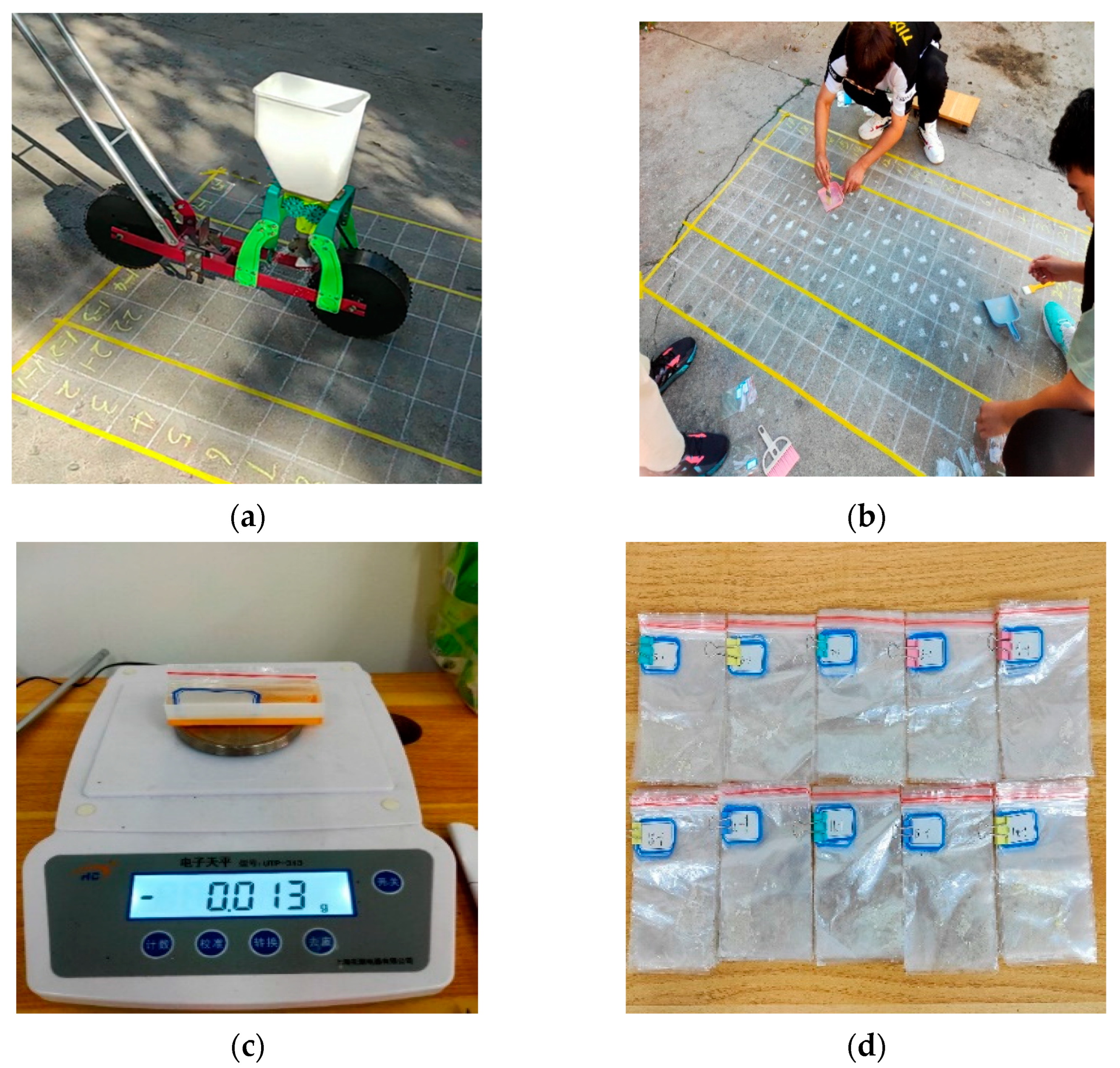
According to the agronomic requirements of corn planting, the coefficient of variation of fertilizer spreading uniformity needs to meet the requirements of NY/T 1003-2006 <Technical Specification for Fertilizer Application Machinery Quality Evaluation> [36,37], and in order to seek the optimal combination between relevant factors, the height X2 is determined to be 400 mm, the transversal fertilizer uniformity coefficient Y1 and longitudinal fertilizer uniformity coefficient Y2 are less than 0.15 as the optimization index, and the solved range of parameters is the constraint for the optimization solution. The optimization results are shown in Figure 11.
In order to facilitate the actual processing to reduce the cost and the stability of the fertilizer spreading operation, the median swing angle X1 = 52°, height X2 = 400 mm, and minimum width X3 = 50 mm were determined as the optimal combination of parameters.
The simulation model was re-established with the optimized parameters, and the simulation validation test was conducted. The test was repeated three times, and the test results were averaged. The test results showed that the optimized transversal fertilizer uniformity coefficient Y1 and longitudinal fertilizer uniformity coefficient Y2 are 0.132 and 0.135, which are less than 0.15 and are within the optimization criterion and prove that the optimized simulation parameters are correct.

4. Validation Test

A validation test of the corn-overlapped strip spreader was carried out to verify the feasibility of the simulation method mentioned above and the correctness of the optimization results of the corn-overlapped strip spreader. The experiment was conducted in September 2021 at the Intelligent Agricultural Equipment Engineering Laboratory of Harbin Cambridge University. The experiment was conducted realistically by replicating the grid division of the statistical simulation area, with a total of 160 fertilizer collection points in 8 columns and 20 rows in a test area of 2 m × 1.2 m, with a row spacing of 15 cm and a column spacing of 20 cm.
The experimental procedure is shown in Figure 12 The test device mainly consisted of a fertilizer tank, a fertilizer discharger, a corn-overlapped strip fertilizer spreader, and a walking device, and the corn-overlapped strip spreader was obtained through a 3D printing process [38,39]. A chain drove the walking device and the fertilizer spreader, and the machine′s forward speed was controlled by adjusting the transmission ratio to 0.5 m/s before the test. Before the test, five groups of the same mass of fertilizer were weighed and poured into the fertilizer tank. The front wheel of the whole machine was located at the middle starting line of the test grid along the center line of the grid to advance the operation. At the end of the test, the fertilizer in each grid was collected with a brush and then weighed and counted, and each fertilizer collection bag was labeled with the corresponding grid position to facilitate the tallying of test results. The test was repeated five times, the data from each test were weighed with an electronic balance, and a statistical interval was selected to calculate its horizontal and vertical uniformity coefficients, as shown in Table 7.
The results showed that the corn-overlapped strip fertilizer spreading device could complete the spreading operation smoothly, and the average values of the transversal fertilizer uniformity coefficient and longitudinal fertilizer uniformity coefficient were 0.1427 and 0.1471, with deviation values of 8.11% and 9.01%, respectively, from the simulation test, which was in line with the ±10% deviation range. A possible reason for the deviation might be the deviation of the urea particles from the ideal particles in the simulation, and the bouncing of the urea particles on the cement ground during the actual operation, resulting in a slight deviation of the fertilizer spreading process on the cement ground from the simulation. The departure was not significant, indicating that the whole machine worked well.

5. Conclusions

(1)
In this study, we designed a corn-overlapped strip fertilizer spreading device in without an external power source. By configuring a passive overlapping spreading method with a three-branch split chamber structure, uniform spreading of fertilizer in strips was achieved. Based on the theoretical analysis of the fertilizer particle motion model, the main factors affecting the distribution pattern of fertilizers were angle α, width N, and height H.
(2)
The single-factor ternary orthogonal rotational combination response surface simulation test was carried out with angle α, width N, and height H as test factors and the transversal fertilizer uniformity coefficient and longitudinal fertilizer uniformity coefficient as test indicators. The regression model was established using Design-expert8.0.6 software to derive the variation relationship of the test factors on the test indexes. The test results showed that the optimized transversal fertilizer uniformity coefficient and longitudinal fertilizer uniformity coefficient were less than 0.15% when the pendulum angle = 52°, height = 400 mm, and width = 50 mm, which were under the optimization criterion.
(3)
A verification test was carried out under the optimal combination of parameters for the simulation tests with the simulation conditions as the standard. The test results were consistent with the simulation results within the error range, and the deviation values of the transversal fertilizer uniformity coefficient and longitudinal fertilizer uniformity coefficient were 8.11% and 9.01%, respectively, which was in line with the ± 10% deviation range. The corn-overlapped strip fertilizer spreader was able to complete the fertilizer spreading operation smoothly.

6. Patents

Two patents have been applied in China in this manuscript (Patent No. ZL202121578688.3 No. ZL202021054986.8).

Author Contributions

G.D. and N.M. designed the research. N.M., X.J. and F.Z. participated in the measurements and data analysis, and N.M. wrote the first draft of the manuscript. G.D. and N.M. revised and edited the final version of the manuscript. G.D. and W.J. are responsible for funding acquisition. All authors have read and agreed to the published version of the manuscript.

Funding

This research was funded by the National Key Research and Development Program Project, grant number 2018YFD0201001, Northeast Forestry University Fundamental Research Funds for Central Universities, grant number 2572020BF03, and Harbin Cambridge University Key Scientific Research Application Research Project, grant number JQZKY2022021.

Institutional Review Board Statement

Not applicable.

Informed Consent Statement

Not applicable.

Data Availability Statement

Not applicable.

Conflicts of Interest

The authors declare no conflict of interest.

References

  1. He, Y.; Zhao, X.; Li, C.; Dou, H.; Li, S.; Wang, X. Research statusand analysis of corn topdressing mechan-ical fertilization technology. Agric. Mech. Res. 2021, 43, 1–9. [Google Scholar]
  2. Tan, S.; Xie, D.; Ni, J.; Chen, F.; Ni, C.; Shao, J.; Zhu, D.; Wang, S.; Lei, P.; Zhao, G.; et al. Characteristics and Influencing Factors of Chemical Fertilizer and Pesticide Applications by Farmers in Hilly and Mountainous Areas of Southwest, China. Ecol. Indic. 2022, 143, 109346. [Google Scholar] [CrossRef]
  3. Chen, A.; Tian, J.; Wu, H.; Zhang, H.; Li, B. Development status of organic fertilizers and their supporting fertiliza-tion machinery. Use Maint. Agric. Mach. 2022, 9, 1–5. [Google Scholar]
  4. Gao, J.; Peng, C.; Shi, Q. Study on the High Chemical Fertilizers Consumption and Fertilization Behavior of Small Rural Househo in China: Discovery from 1995~2016 National Fixed Point Survey Data. Manag. World 2019, 35, 120–132. [Google Scholar]
  5. Zhao, J.; Wang, X.; Tian, H.; Lu, Y.; Guo, C.; Liu, H. A Fertilizer Discharge Detection System Based on Point Cloud Data and an Efficient Volume Conversion Algorithm. Comput. Electron. Agric. 2021, 185, 106131. [Google Scholar] [CrossRef]
  6. Bu, H.; Yu, S.; Dong, W.; Zhang, L.; Xia, Y. Analysis of the Effect of Bivariate Fertilizer Discharger Control Sequence on Fertilizer Discharge Performance. Agriculture 2022, 12, 1927. [Google Scholar] [CrossRef]
  7. Zeng, Z.; Ma, X.; Cao, X.; Li, Z.; Wang, X. Application status and prospect of discrete element method in agricultural engineering research. J. Agric. Mach. 2021, 52, 1–20. [Google Scholar]
  8. Liu, H.; Du, C.; Yin, L.; Zhang, G. Study on the shape and control of the side-throwing jet of organic fertilizer on an inclined opposed disk. J. Agric. Mach. 2022, 53, 168–177. [Google Scholar]
  9. Liu, Z.; Wang, Q.; Li, H.; He, J.; Lu, C.; Yu, C. Analysis and test of fertilizer application path of pneumatic seed and fertilizer hole application device coupled with CFD-DEM. J. Agric. Eng. 2019, 35, 18–25. [Google Scholar]
  10. Song, C.; Zhou, Z.; Wang, G.; Wang, X.; Zang, Y. Optimization of the structural parameters of the sheaves of the fertiliser UAV sheaves. J. Agric. Eng. 2021, 37, 1–10. [Google Scholar]
  11. Liu, X.; Lü, Q.; Li, G.; Wang, J.; Yan, D.; Yang, L.; Liu, E. Design Optimization and Experimental Verification of Spiral Cone Centrifugal Fertilizer Apparatus Based on the Discrete Element Method. Processes 2023, 11, 199. [Google Scholar] [CrossRef]
  12. Ding, S.; Bai, L.; Yao, Y.; Yue, B.; Fu, Z.; Zheng, Z.; Huang, Y. Discrete Element Modelling (DEM) of Fertilizer Dual-Banding with Adjustable Rates. Comput. Electron. Agric. 2018, 152, 32–39. [Google Scholar] [CrossRef]
  13. Wang, J.; Qi, X.; Xu, C.; Wang, Z.; Jiang, Y.; Tang, H. Design Evaluation and Performance Analysis of the Inside-Filling Air-Assisted High-Speed Precision Maize Seed-Metering Device. Sustainability 2021, 13, 5483. [Google Scholar] [CrossRef]
  14. Shaikh, S.A.; Li, Y.; Ma, Z.; Chandio, F.A.; Tunio, M.H.; Liang, Z.; Solangi, K.A. Discrete Element Method (DEM) Simulation of Single Grouser Shoe-Soil Interaction at Varied Moisture Contents. Comput. Electron. Agric. 2021, 191, 106538. [Google Scholar] [CrossRef]
  15. Landry, H.; Laguë, C.; Roberge, M. Discrete Element Representation of Manure Products. Comput. Electron. Agric. 2006, 51, 17–34. [Google Scholar] [CrossRef]
  16. Lv, J.; Sun, Y.; Li, J.; Li, Z.; Liu, Z. Design and test of vertical organic fertilizer spiral spreading device. J. Agric. Eng. 2020, 36, 19–28. [Google Scholar]
  17. Zinkevičienė, R.; Jotautienė, E.; Jasinskas, A.; Kriaučiūnienė, Z.; Lekavičienė, K.; Naujokienė, V.; Šarauskis, E. Determination of Properties of Loose and Granulated Organic Fertilizers and Qualitative Assessment of Fertilizer Spreading. Sustainability 2022, 14, 4355. [Google Scholar] [CrossRef]
  18. Dang, Y.; Yang, G.; Wang, J.; Zhou, Z.; Xu, Z. A Decision-Making Capability Optimization Scheme of Control Combination and PID Controller Parameters for Bivariate Fertilizer Applicator Improved by Using EDEM. Agriculture 2022, 12, 2100. [Google Scholar] [CrossRef]
  19. Yang, L.; Chen, L.; Zhang, J.; Liu, H.; Sun, Z.; Sun, H.; Zheng, L. Fertilizer Sowing Simulation of a Variable-Rate Fertilizer Applicator Based on EDEM. IFAC PapersOnLine 2018, 51, 418–423. [Google Scholar] [CrossRef]
  20. Mudarisov, S.; Farkhutdinov, I.; Khamaletdinov, R.; Khasanov, E.; Mukhametdinov, A. Evaluation of the Significance of the Contact Model Particle Parameters in the Modelling of Wet Soils by the Discrete Element Method. Soil Tillage Res. 2022, 215, 105228. [Google Scholar] [CrossRef]
  21. Li, A.; Han, Y.; Jia, F.; Zhang, J.; Meng, X.; Chen, P.; Xiao, Y.; Zhao, H. Examination Milling Non-Uniformity in Friction Rice Mills Using by Discrete Element Method and Experiment. Biosyst. Eng. 2021, 211, 247–259. [Google Scholar] [CrossRef]
  22. Dun, G.; Chen, H.; Feng, Y.; Yang, J.; Li, A.; Cha, S. Parameter optimization and test of key components of fertilizer blending device based on EDEM software. J. Agric. Eng. 2016, 32, 36–42. [Google Scholar]
  23. Liu, J.-S.; Gao, C.-Q.; Nie, Y.-J.; Yang, B.; Ge, R.-Y.; Xu, Z.-H. Numerical Simulation of Fertilizer Shunt-Plate with Uniformity Based on EDEM Software. Comput. Electron. Agric. 2020, 178, 105737. [Google Scholar] [CrossRef]
  24. Pocius, A.; Jotautiene, E.; Pekarskas, J.; Mieldazys, R.; Jasinskas, A. Research of particle geometrical parameters and aerodynamic features of granular organic compost fertilizers. Eng. Rural. Dev. 2014, 13, 401–406. [Google Scholar]
  25. Zinkevičienė, R.; Jotautienė, E.; Juostas, A.; Comparetti, A.; Vaiciukevičius, E. Simulation of Granular Organic Fertilizer Application by Centrifugal Spreader. Agronomy 2021, 11, 247. [Google Scholar] [CrossRef]
  26. Lv, H.; Yu, J.; Fu, H. Simulation of the Operation of a Fertilizer Spreader Based on an Outer Groove Wheel Using a Discrete Element Method. Math. Comput. Model. 2013, 58, 842–851. [Google Scholar] [CrossRef]
  27. Kim, Y.-S.; Siddique, M.A.A.; Kim, W.-S.; Kim, Y.-J.; Lee, S.-D.; Lee, D.-K.; Hwang, S.-J.; Nam, J.-S.; Park, S.-U.; Lim, R.-G. DEM Simulation for Draft Force Prediction of Moldboard Plow According to the Tillage Depth in Cohesive Soil. Comput. Electron. Agric. 2021, 189, 106368. [Google Scholar] [CrossRef]
  28. Van Liedekerke, P.; Tijskens, E.; Dintwa, E.; Rioual, F.; Vangeyte, J.; Ramon, H. DEM Simulations of the Particle Flow on a Centrifugal Fertilizer Spreader. Powder Technol. 2009, 190, 348–360. [Google Scholar] [CrossRef]
  29. Zhao, S.; Gao, L.; Yuan, Y.; Hou, L.; Zhang, X.; Yang, Y. The law of corn stalk movement in deep subsoiling operation based on discrete element method. J. Agric. Eng. 2021, 37, 53–62. [Google Scholar]
  30. Song, X.; Dai, F.; Zhang, F.; Wang, D.; Liu, Y. Calibration of DEM Models for Fertilizer Particles Based on Numerical Simulations and Granular Experiments. Comput. Electron. Agric. 2023, 204, 107507. [Google Scholar] [CrossRef]
  31. Zhang, G.; Wang, Y.; Liu, H.; Ji, C.; Hou, Q.; Zhou, Y. Design and test of centrifugal side-throw lotus root fertilizer spreader. J. Agric. Eng. 2021, 37, 37–47. [Google Scholar]
  32. Yinyan, S.; Man, C.; Xiaochan, W.; Odhiambo, M.O.; Weimin, D. Numerical Simulation of Spreading Performance and Distribution Pattern of Centrifugal Variable-Rate Fertilizer Applicator Based on DEM Software. Comput. Electron. Agric. 2018, 144, 249–259. [Google Scholar] [CrossRef]
  33. Zhang, M.; Tang, Y.; Zhang, H.; Lan, H.; Niu, H. Parameter Optimization of Spiral Fertilizer Applicator Based on Artificial Neural Network. Sustainability 2023, 15, 1744. [Google Scholar] [CrossRef]
  34. Barbosa, L.A.P. Modelling the Aggregate Structure of a Bulk Soil to Quantify Fragmentation Properties and Energy Demand of Soil Tillage Tools in the Formation of Seedbeds. Biosyst. Eng. 2020, 197, 203–2159. [Google Scholar] [CrossRef]
  35. Bai, J.; Hao, F.; Cheng, G.; Li, C. Machine Vision-Based Supplemental Seeding Device for Plug Seedling of Sweet Corn. Comput. Electron. Agric. 2021, 188, 106345. [Google Scholar] [CrossRef]
  36. Wang, Y.; Xue, W.; Ma, Y.; Tong, J.; Liu, X.; Sun, J. DEM and Soil Bin Study on a Biomimetic Disc Furrow Opener. Comput. Electron. Agric. 2019, 156, 209–216. [Google Scholar] [CrossRef]
  37. Shi, Y.; Xin (Rex), S.; Wang, X.; Hu, Z.; Newman, D.; Ding, W. Numerical Simulation and Field Tests of Minimum-Tillage Planter with Straw Smashing and Strip Laying Based on EDEM Software. Comput. Electron. Agric. 2019, 166, 105021. [Google Scholar] [CrossRef]
  38. Jadhav, A.; Jadhav, V.S. A Review on 3D Printing: An Additive Manufacturing Technology. Mater. Today Proc. 2022, 62, 2094–2099. [Google Scholar] [CrossRef]
  39. Shahrubudin, N.; Lee, T.C.; Ramlan, R. An Overview on 3D Printing Technology: Technological, Materials, and Applications. Procedia Manuf. 2019, 35, 1286–1296. [Google Scholar] [CrossRef]
Figure 1. A structural diagram of the corn-overlapped strip fertilizer spreader; (a) structural model diagram; (b) cross-sectional view: 1. fattening small plates, 2. lower fertilizer spreading tube, 3. upper fertilizer spreading tube, 4. fertilizer funnel, 5. fertilizer falling path, 6. fertilizer cone, 7. fattening bulges.
Applsci 13 02559 g001
Figure 2. Schematic diagram of the fertilizer strip: 1. fattening small plates, 2. fattening bulges, 3. single plate spreading area, 4. fertilizer spreading overlap zone.
Applsci 13 02559 g002
Figure 3. Analysis of fertilizer spreading campaigns.
Applsci 13 02559 g003
Figure 4. Fertilizer vertical spreading movement.
Applsci 13 02559 g004
Figure 5. Simulation test model. 1. Ground, 2. corn root stubble, 3. soil particles factory, 4. fertilizer particles factory, 5. corn-overlapped strip fertilizer spreader.
Applsci 13 02559 g005
Figure 6. Simulation process. 1. Soil particles, 2. soil particles factory, 3. fertilizer particles factory, 4. fertilizer particles.
Applsci 13 02559 g006
Figure 7. Fertilizer spreading process in simulation test. (a) 0.72 s, (b) 1.22 s, (c) 1.94 s, (d) 2.83 s.
Applsci 13 02559 g007
Figure 8. Schematic diagram of fertilizer monitoring area.
Applsci 13 02559 g008
Figure 9. The influence curve of the single factor test. (a) Effect of angle on the transversal fertilizer uniformity coefficient and longitudinal fertilizer uniformity coefficient, (b) effect of width on the transversal fertilizer uniformity coefficient and longitudinal fertilizer uniformity coefficient, (c) effect of height on the transversal fertilizer uniformity coefficient and longitudinal fertilizer uniformity coefficient.
Applsci 13 02559 g009
Figure 10. Angle–width response surface graph.
Applsci 13 02559 g010
Figure 11. Angle–height response surface graph.
Applsci 13 02559 g011
Figure 12. Experimental procedure. (a) Testing device, (b) fertilizer collection, (c) weighing process, (d) fertilizer collection bags.
Applsci 13 02559 g012
Table 1. Global variable parameter setting.
ProjectPropertyValue
Poisson ratio0.25
Urea fertilizer granuleShear modulus (Pa)1.04 × 10⁷
Density (kg·m3)1345
Poisson ratio0.25
Soil particlesShear modulus (Pa)1 × 10⁸
Density (kg·m3)2000
Poisson ratio0.28
Fertilizer spreading deviceShear modulus (Pa)8.0 × 10⁹
Density (kg·m3)1240
Corn rootsPoisson ratio0.33
Shear modulus (Pa)6.39
Density (kg·m3)107.64
Urea fertilizer granule–urea fertilizer granuleRestitution coefficient0.60
Static friction coefficient0.40
Rolling friction coefficient0.01
Urea fertilizer granule–soil particlesRestitution coefficient0.60
Static friction coefficient0.50
Rolling friction coefficient0.50
Urea fertilizer granule–corn rootsRestitution coefficient0.60
Static friction coefficient0.60
Rolling friction coefficient0.20
Urea fertilizer granule–fertilizer spreading deviceRestitution coefficient0.01
Static friction coefficient0.02
Rolling friction coefficient0.01
Soil particles–corn rootsRestitution coefficient0.60
Static friction coefficient0.60
Rolling friction coefficient0.02
Table 2. Single factor test results of swing angle, height, and width.
Test FactorsRange of Test FactorsTransversal Fertilizer
Uniformity Coefficient Y1
Longitudinal Fertilizer
Uniformity Coefficient Y2
Angle α30°0.79010.4293
37.5°0.70240.3290
45°0.61900.2213
52.5°0.62260.2127
60°0.58280.1356
Width N250 mm0.89020.5160
300 mm0.82980.4489
350 mm0.81390.4356
400 mm0.77930.4112
450 mm0.71050.28952
Height H400.81370.4351
450.74020.3296
500.61900.2213
550.5970.1850
600.59120.2168
Table 3. Factor level coding table.
CodeFactor
Angle X1/(°)Height X2/mmWidth X3/mm
1.68260.00450.0060.00
156.96429.7357.97
052.50400.0055.00
−148.04370.2752.03
−1.68245.00350.0050.00
Table 4. Simulation test scheme and results.
CodeTest FactorTest Indexes
Angle X1/(°)Height X2/mmWidth X3/mmThe Transversal Fertilizer
Uniformity Coefficient Y1
The Longitudinal Fertilizer Uniformity Coefficient Y2
152.50400.0055.000.17630.1129
256.96429.7357.970.17000.1258
348.04370.2757.970.11010.1324
460.00400.0055.000.13540.1096
552.50400.0055.000.14450.1306
652.50400.0055.000.12750.1041
752.50400.0055.000.14580.1659
852.50450.0055.000.09750.1069
956.96370.2757.970.21100.1275
1052.50400.0060.000.13610.0750
1152.50400.0055.000.15590.1165
1252.50400.0055.000.14040.1385
1352.50350.0055.000.13020.1097
1448.04429.7357.970.09970.2188
1552.50400.0055.000.14880.2077
1656.96370.2752.030.14680.2077
1748.04429.7352.030.14280.1877
1848.04370.2752.030.17180.2077
1952.50400.0055.000.14580.2537
2052.50400.0050.000.12180.2078
2152.50400.0055.000.14480.2077
2245.00400.0055.000.14780.2077
2356.96400.0055.000.17630.1128
Table 5. Analysis of variance for lateral uniformity coefficient.
Evaluation Indicators of the Transversal Fertilizer Uniformity Coefficient Y1
Source of VarianceSquare
Sum
Degree of FreedomMean SquareF-Valuep-ValueSignificance
Model0.01091.137 × 10−34.440.0078***
X12.170 × 10−312.170 × 10−38.480.0121**
X21.774 × 10−311.774 × 10−36.930.0207**
X31.196 × 10−311.196 × 10−34.680.0498**
X1×21.347 × 10−811.347 × 10−85.264 × 10−50.9943
X1X38.920 × 10−418.920× 10−43.490.0846*
X2X36.478 × 10−416.478 × 10−42.530.1356
X121.125 × 10−311.125 × 10−34.400.0561*
X225.053 × 10−615.053 × 10−60.0200.8904
X322.4 × 10−312.4 × 10−39.380.0091***
Residual3.326 × 10−3132.558 × 10−49.380.0091
Misfit term2.002 × 10−354.004 × 10−42.420.1279
Pure error1.324 × 10−381.655 × 10⁻⁴
Total variation0.01422
Note: *** p < 0.01 (highly significant); ** 0.01 < p < 0.05 (significant); * p > 0.05 (non-significant); p > 0.1 (non-effect).
Table 6. Analysis of variance of average velocity of fertilizer particles.
Evaluation Indicators of the Longitudinal Fertilizer Uniformity Coefficient Y2
Source of VarianceSquare
Sum
Degree of FreedomMean SquareF-Valuep-ValueSignificance
Model0.05095.588 × 10−313.65<0.0001***
X12.469 × 10−312.469 × 10−36.030.0289**
X24.528 × 10−414.528 × 10−41.110.3120
X33.237 × 10−313.237 × 10−37.910.0147**
X1X25.809 × 10−415.809 × 10−41.420.2548
X1X37.163 × 10−417.163 × 10−41.750.2086
X2X31.510 × 10−411.510× 10−40.370.5541
X120.02410.02459.63<0.0001***
X220.01410.01434.78<0.0001***
X324.552 × 10−314.552 × 10−311.120.0054***
Residual5.32 × 10−3134.092 × 10−4
Misfit term2.879 × 10−355.758 × 10−41.890.2024
Pure error2.441 × 10−383.051 × 10⁻⁴
Total variation0.05622
Note: *** p < 0.01 (highly significant); ** 0.01 < p < 0.05 (significant); p > 0.1 (non-effect).
Table 7. Test results.
Serial NumberThe Transversal
Fertilizer Uniformity Coefficient
The Longitudinal
Fertilizer Uniformity Coefficient
10.14510.1487
20.15670.1378
30.13540.1575
40.12890.1459
50.14760.1457
Average value0.14270.1487
Simulation value0.1320.135
Relative error−8.11%−9.01%
Disclaimer/Publisher’s Note: The statements, opinions and data contained in all publications are solely those of the individual author(s) and contributor(s) and not of MDPI and/or the editor(s). MDPI and/or the editor(s) disclaim responsibility for any injury to people or property resulting from any ideas, methods, instructions or products referred to in the content.

