Abstract
There has been a large amount of scientific research carried out to date on the impact of salty backwash brine from domestic water softeners (WS) on domestic wastewater treatment plants (DWTPs). Experts and practitioners agree that the impact is harmful and there is still a need to look for new technologies. The study of the effect of an increased sodium chloride (NaCl) concentration after softener regeneration is important from the point of view of the operation of DWTPs and soil properties. This paper presents the results of a field study of the concentration of NaCl at the septic tank (ST) drainage point, into which the grey water from the regeneration of the water softener flowed. During the six-month measurements (recorded every 1 min), an increase in NaCl concentration was observed in the septic tank outflow, from an average NaCl concentration of 1.5 g·L−1—between regenerations—to an average concentration of 4.5 g·L−1—after water softener regeneration. The increased NaCl concentration decreased significantly up to 2 days after the water softener regeneration. Temperature changes in the treated wastewater were also measured—during the winter period, temperature differences of up to 10 °C per day were recorded. In the second part of the study, conducted on a semi-technical scale, the effect of brine from the regeneration of the water softener on the hydraulic conductivity (Ks) of the soil from the infiltration drain of the DWTPs studied was assessed. The Ks was determined by analysing the time it took the water to soak into the soil, using the Van Hoorn equation. The results and statistical analysis indicate an increased salt content in the soil absorbing the brine, which may have been influenced by the reduced absorption and capacity of the drain due to adverse physico-chemical changes.
1. Introduction
In non-urbanised areas where, for technical or economic reasons, it is not possible to connect to the sewerage network, drainless reservoirs or domestic wastewater treatment plants (DWTPs) are used. The latter are becoming increasingly popular due to their lower odour nuisance and lower maintenance costs in comparison to the costs incurred for the disposal of wastewater from drainless reservoirs [1,2].
The simplest DWTPs are those consisting of a septic tank (ST) and a wastewater leaching system (e.g., a subsurface leaching system) [3,4]. The ST is usually the first unit in a domestic wastewater treatment plant and is used for the primary treatment of wastewater. More extensive domestic wastewater treatment plants utilise aerobic biological processes (flow-through activated sludge, sequencing batch reactor (SBR), trickling filter) after the preliminary treatment of wastewater, e.g., in a septic tank [5,6]. Effective sorption materials of various origins are also increasingly used in DWTPs. Sorption is a frequently used method of water purification and uses, e.g., polymer composites, membranes, graphene, carbon nanomaterials, and natural adsorbents such as aerogels of biological and natural origin adsorbents. The latter can be further divided into organic and inorganic materials [7]. Currently, adsorbents used to remove various types of pollutants from water, including oils, antibiotics, and heavy metals, can be divided into natural—of organic and inorganic origin—and synthetic materials [8,9].
In a septic tank, the wastewater treatment process mainly takes place through the sedimentation of solids with a higher density than the liquid in the tank. The solids settling to the bottom form sludge. Meanwhile, for the suspended solids lighter than the liquid in the tank, a flotation process occurs, resulting in the formation of scum in the vicinity of the wastewater table. Anaerobic biological processes have little influence on the treatment of wastewater discharged from septic tanks [10,11,12]. Psychrophilic fermentation takes place in the accumulated sludge at the bottom of the tank due to the low temperature inside the septic tank [9]. A study conducted in Poland observed a range of liquid temperatures in the septic tank from 3 to 19 °C, with an annual air temperature of −13 to 30 °C [13].
The density of wastewater flowing into a septic tank is influenced by the concentration of suspended solids and their temperature [14,15]. Wastewater with a high content of suspended solids acts as if it has a higher density than the wastewater in the septic tank and settles to the bottom. As a result, the slab velocity is much higher than the theoretical one, and the septic tank has worse efficiency. When density differences are influenced by the temperature, there are two possibilities. The first is that when the wastewater entering the septic tank is cooler than the wastewater in the tank, a bottom slab is formed, which lifts the sludge accumulated at the bottom. This phenomenon is referred to as spring turnover or boil of the septic tank and may result in a deterioration of the quality of the treated wastewater. This situation is particularly prevalent during the summer when cold water is used more frequently. Instances where warmer wastewater causes a surface slab are particularly noticeable during winter. In this situation, very little treated wastewater enters the septic tank outlet [2]. In order to prevent the negative effects of the temperature difference between the inlet wastewater and the interior of the septic tank, it is recommended to use special inlet and outlet design solutions in septic tanks [13,16] or dedicated connections between chambers for multi-chamber tanks [17].
In the last few years, water softeners (WS) have been installed in detached houses to improve water quality. The application of such a device aims to reduce the hardness of the water, among other things, in order to reduce the adverse effects of limescale and sediment deposits on the water supply, heating systems, and the devices that use the water. Water softening in individual installations takes place on the basis of ion exchange [18,19]. As a result of the water-softening process, calcium and magnesium cations, responsible for the hardness of the water, are exchanged for sodium cations. Once the ion-exchange capacity of the bed has been exhausted to a certain extent, a regeneration process takes place from time to time in the SW by automatically flushing the bed with a solution of water and salt, called brine. The solution contains a high concentration of sodium ions with which the bed is re-supplied with sodium cations [20,21,22]. During the regeneration process, grey water is produced, which is usually discharged into the sewage system [20].
It is possible that there may be a negative impact of water softener regeneration grey waters on the operation of DWTPs, both in relation to biological wastewater treatment and the leaching system [23]. In the context of biological methods [24], the influent brine may interfere with the wastewater treatment bacterial microflora (present in the form of free-floating activated sludge or immobilised on a biomass carrier), reducing the efficiency of the domestic treatment plant. An important factor of this impact is, among other things, the size of the tank (e.g., septic tank) where the wastewater pre-treatment is performed. In wastewater infiltration systems [25], in turn, crystallising salt can have a negative effect. In the case of a soakaway pit, due to the point of introduction of wastewater, the crystallising salt deposits can, after a few or several years, reach a salt layer thick enough to obstruct the free flow of wastewater into the native soil. With infiltration drainage, on the other hand, the negative impact may be less significant compared to the previously discussed systems, due to the distribution of treated wastewater over larger areas.
As demonstrated in a laboratory study by Gross and Bounds (2007), the brine from a softener rinse contributed to the stratification of the zones in the tank and the increase in the sludge layer [26]. Based on the observed phenomenon, it was concluded that the salty water had accumulated at the bottom of the tank and lifted the sludge, which may have adversely affected the proper operation of the domestic wastewater treatment plant. Higgins and Novak (1997a) showed that high concentrations of sodium can lead to deflocculation in activated sludge systems [27]. Novak et al. (1997a) also demonstrated that when the monovalent-to-divalent cation ratio exceeded two, effluent characteristics in activated sludge systems deteriorated.
Promoting the concept of “reduce, reuse, and recycle” in DWTPs [21] and following the principles of a circular economy, brine used in various industries needs to be recovered and/or managed in an environmentally friendly manner [28]. In the softener regeneration process discussed in this paper, the brine is traditionally directed to a cesspool, discharged underground into a dry well or routed through building pipes to grade level. Excessive amounts of salt in the soil may result in, among other things, physiological drought for plants, which is related to the loss of their ability to extract mineral nutrients from the soil solution [25]. Sodium also influences the swelling of some soil particles, making it much more difficult for water to infiltrate the soil. The rationale and method for controlling the infiltration of grey waters into the soil, along with other negative effects, are presented later in this paper.
The primary objective of this study was to carry out six-month field tests at a DWTP facility equipped with a septic tank and measure the concentration of sodium chloride at the outflow of a septic tank into which the grey waters from the regeneration of a water softener (WS) flowed. The regeneration of the bed of the WS occurred cyclically and consisted of flushing it with a salt solution. The temperature change of the treated effluent was also recorded during the experiment, together with temperature measurements in a control well. The aim of the second part of the study was to evaluate the effect of the SW regeneration brine on the hydraulic conductivity of the soil, carried out on a semi-technical scale using filter columns.
2. Materials and Methods
2.1. Septic Tank Study
The domestic wastewater treatment plant (DWTP) that was included in the study was located in the city of Ujazd, Łódzkie Voivodship, Poland. The research was carried out there in 2022 from January to June. Its primary operation was a septic tank (3)—the subject of this study—made of polyurethane, with an active volume of 2.0 m3 (see Figure 1).
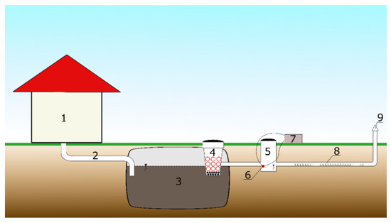
Figure 1.
Simplified diagram of the DWTP as a test stand: (1) detached house, (2) the duct, (3) septic tank, (4) filter basket, (5) control well, (6) measuring probe, (7) data logger, (8) infiltration drainage, (9) exhaust pipe.
At the outlet of the septic tank (3), there was a filter basket (4) filled with volcanic rock–pozzolan (distributor company Tycner Sp. z o.o., Mielec, Poland), which is shown in the photos below (Figure 2).
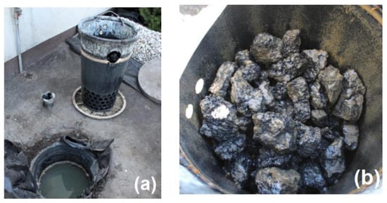
Figure 2.
Filter basket filled with volcanic rock (pozzolana), installed on the septic tank outflow: (a) external view, (b) internal view.
The pozzolan used was pure material of volcanic origin, without admixtures or metallurgical waste. The main components of this material were calcium oxide (CaO, 57.02%), silicon(IV) oxide (SiO2, 21.77%), magnesium oxide (MgO, 2.71%), aluminium(III) oxide (Al2O3 2.59%), sulphur(VI) oxide (SO3, 2.41%), and iron(III) oxide (Fe2O3, 0.65%) [29]. Due to its excellent sorptive properties, it is very often used as a filter material for domestic wastewater treatment plants. Generally, the filling is supposed to slow down the rate of wastewater flow through the septic tank and additionally act as a strainer, reducing the amount of suspended solids in the outflow from the ST. Being a material of volcanic origin, pozzolan is characterised by a highly varied yet significantly developed specific surface area, ideal for the formation of a biological membrane (bacterial biofilm) [30]. Other features of this material include its high chemical and mechanical stability, which results in an extended shelf life [29]. The high quality of pozzolan ensures the effective operation of the filter—retaining the non-liquid fraction (suspended solids) upstream of the infiltration section (drainage) while counteracting blockages in sewage infiltration systems.
Behind the ST provided with a filter basket (3 and 4) was a control well (5) with a volume of several litres, from which the treated wastewater entered the infiltration drain (8) (see Figure 1). The filter basket should be visually inspected for clogging twice a year. In the event of clogging, the filter material in the basket should be removed for thorough flushing with a high-pressure water jet. Then, the filter material is installed in the basket and refilled if necessary. The filling of the filter basket does not need to be replaced; cures are usually replaced every 10 years. The price of the material (volcanic rock) for a standard basket is about PLN 100.
The study began approximately one year after the installation of the water softener (Viessmann Aquahome Duo 30-N, Viessmann GmbH & Co KG, Allendorf, Germany), while the domestic wastewater treatment plant had already been operating for several years. The ST was emptied of accumulated sludge regularly (once a year). Regeneration of the water softener bed occurred cyclically, after approximately every 4.0 m3 of softened water. The bed was flushed with a salt solution containing about 3.2 kg of salt and about 105 L of water on average, used for the regeneration process.
The measurement of the sodium chloride concentration was conducted using the Gravity DFR0300: Analog Electrical Conductivity Sensor/Meter V2 (DFRobot, Richmond, VA, USA) probe (measurement range: from 1 ms·cm−1 to 20 ms·cm−1; accuracy: ±10%). The electrical conductivity was measured, with the simultaneous measurement of the temperature in the distribution well. The end of the probe (6) was installed in the distribution well (5) at the level of the outflow of treated effluent (see Figure 1). The measurement was recorded every minute over a six-month period.
2.2. Annual Costs of Water Softener Use
Based on the current tariffs for water, sewage, and electricity and the market prices for salt, the annual costs of using a domestic water softener were determined.
Charging rates:
- ▪
- Water—3.98 PLN/m3;
- ▪
- Sewage—9.86 PLN/m3;
- ▪
- Electricity—0.9 PLN/kWh;
- ▪
- Salt—60 PLN/25 kg.
The number of regenerations of the device for a period of 1 year, calculated on the basis of household water consumption, was 28 regenerations.
The total annual cost of using the household water softener was 259.96 PLN (see Figure 3a,b). The cost of one regeneration was 9.28 PLN. More than 80% of this amount was the cost of regenerate (salt); water and sewage made up about 15%; electricity accounted for less than 2%. The costs of water and wastewater consumption strongly depend on local tariffs, with different rates applying in each region of Poland. Most devices allow for the duration of the regeneration modes to be changed, e.g., salting, pre-rinsing, etc. These changes reduce water and wastewater consumption by 20 to 50%. Unfortunately, any change requires a water hardness test, so most users opt for the standard settings.
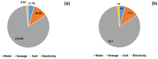
Figure 3.
Annual costs of using a water softener expressed in: (a) PLN and (b) %.
2.3. Study of the Effect of Brine on the Hydraulic Conductivity of the Soil
The second part of the study, carried out at a semi-technical scale, consisted of an analysis of the effect of brine from water softener regeneration on the hydraulic conductivity of the soil. This involved the use of nine pipes with an internal diameter of 105 cm, simulating the action of an infiltration drain into which the grey water from the regeneration of a water softener enters. The pipes, which were given the function of filter columns, were filled with soil extracted at a distance of approximately 4 metres from the infiltration drainage of the DWTPs under study. The excavation of the test material was carried out to a depth of 0.5 m. A layer of stones of about 10 cm was poured onto the bottom of the pipes, and then soil was added to a height of 1 m, as shown in Figure 4.
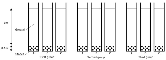
Figure 4.
Diagram of the filter column arrangement used in the study of the effect of brine on the hydraulic conductivity of the soil, at a semi-technical scale; first column group—treated wastewater, second column group—treated wastewater + brine, third column group—water (A, B, C repetitions for a specific group).
The columns were stably placed in a shaded area and secured so that the dosed liquid flowed freely through them. Treated wastewater was poured into the first group (columns: 1a, b, c), treated wastewater and brine into the second group (columns: 2a, b, c), and water into the third group (columns: 3a, b, c). The treated wastewater was collected from the septic tank outflow in the DWTPs under study when the salt concentration did not indicate softener flushing. The brine, on the other hand, was prepared (prior to each injection) using tap water and regeneration salt, with a concentration analogous to that of the brine used in the technical-scale study. In addition, the columns were moistened each time with the appropriate type of liquid before measuring the time it took for the liquid to soak into the soil (see Figure 4).
The hydraulic conductivity Ks was determined by analysing the time it took for the water to soak into the soil, using the Van Hoorn Equation (1):
where:
- KS—hydraulic conductivity, m·s−1;
- r—opening radius, m;
- t—water subsidence time, s;
- H0—initial water level in the opening, m;
- H1—final water level in the opening, m [31].
Hydraulic conductivity testing was performed after 2–3 cycles of brine dosing to the corresponding filter column group.
On the basis of the monthly water meter readings—in terms of water consumed per day at the property in question—it was calculated that the average water consumption was approximately 300 L·d−1 (d—day). In accordance with the diagram (see Figure 5), which shows the permissible hydraulic loading of the soil surface (q) with the wastewater treated in the septic tank—it was determined, in accordance with the source literature [32,33,34], that for the soil located at the household in question, the maximum hydraulic loading was 17.7 L·m−2·d−1 [32,33].
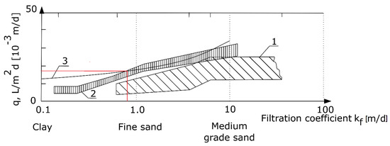
Figure 5.
Permissible hydraulic loading of soil with treated wastewater q, based on (1) Polish technical guidelines for the design of infiltration drains and sand filters from 1971, calculated in accordance with a correction by Błażejewski (2003) [32], (2) French standard DTU 64.1 [33], (3) Laak (1986) [34].
On the basis of the value read from this diagram and the value of the surface area of the filter column (A = 0.00865 m2), the theoretical maximum daily dosage of solution to the filter column was obtained, which was 0.153 L·d−1. In the experiment, however, a dosage of 0.100 L·d−1 was used. A brine concentration of 5.0 g·L−1 at a volume of 0.05 L (dosage calculated at a semi-technical scale) was applied to the second group of columns (2a, b, c) for regeneration, which took place every 10 days (10 d·0.100 L·d−1—i.e., every 1 L). Its dosage was estimated from a proportional calculation of the actual volume of water used between regenerations of the domestic water softener and from an approximate amount of water used to rinse the bed. Rinsing the ion exchange bed consumed approximately 3.9 m3 of water, and the process itself consumed between 105 and 175 L of water.
3. Results and Discussion
3.1. Changes in NaCl Concentration within the Septic Tank
The major type of measurement made during the fieldwork was the recording of changes in the NaCl concentration within the septic tank. Figure 6a presents the salinity measurements obtained over a period of two weeks (13.01–27.01). This was the initial period that the measuring device was installed behind the septic tank. In this graph, a fluctuation in the average NaCl concentration of 1.5 g·L−1 can be observed. At minute 1905 (i.e., 14.01), there was an increase to the highest concentration in the period, at 4.4 g·L−1, which indicates that regeneration was taking place at this time. Twelve days later (26.01), i.e., at minute 18,797, another increase was observed—one of the highest concentrations of the two weeks in question, at 3.5 g·L−1. Due to the time of occurrence, which was 8.23 a.m., the presence of grey waters from the water treatment plant may be inferred.
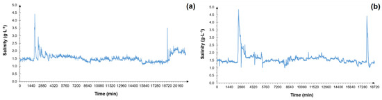
Figure 6.
Changes in the NaCl concentration in the septic tank outflow (a) between 13 and 27 January and (b) between 31 May and 14 June.
Figure 6b presents the next two weeks of salinity measurements, six months after the beginning of the study (31.05–14.06). The average NaCl concentration in the treated wastewater during this period was 1.6 g·L−1. Water softener regeneration occurred twice: at minute 2560, when the maximum NaCl concentration in the septic tank outflow was 4.9 g·L−1, and at minute 17818, with a maximum value of 4.3 g·L−1.
Figure 6a,b shows that the increased NaCl concentration level after regeneration lasted for approximately 1.5 to 2 days, after which it returned to the average concentration. Based on these graphs, an increased concentration of NaCl in the wastewater after the softener regeneration period was also noted. Similar results related to the increase in the NaCl concentration after the softener regeneration and such uncontrolled fluctuations in the brine concentration have also been observed by other researchers in pioneering experiments [35,36]. The destabilisation of the system, caused by the increase in NaCl concentration, inhibited the wastewater treatment processes.
The next graph (Figure 7) demonstrates an example of the NaCl concentration over a two-day period from the start of the regeneration on 2 June.
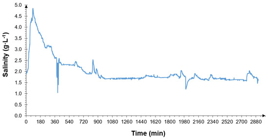
Figure 7.
Example of a two-day period of NaCl concentration measurements at the septic tank outflow, after the start of water softener regeneration.
The above-discussed changes in the NaCl concentration at the septic tank outflow are in line with laboratory studies carried out by Gross and Bounds (2007) [26]. The authors recognised that water backwash brine can be detrimental to onsite wastewater treatment system performance. The researchers concluded that concentrated salt water accumulates at the bottom of a septic tank receiving brine and can be periodically discharged to the advanced treatment unit, with consequent adverse effects on the treatment performance [26]. In the case of the presented studies regarding the grey water from the water softener regeneration, the wastewater most likely did not mix with the liquid in the septic tank and rather accumulated in the clarification zone or moved the accumulated sludge in the tank. The zone of clarification was between the sludge accumulated on the bottom and the floating blanket near the water table. This was followed by leaching of the grey water from the septic tank over a period of up to 2 days, which was associated with a period of an increased NaCl concentration at the septic tank outflow.
From the results of the measurements, presented in Figure 7, it may be concluded that the regeneration of the water softener started at around 7:00 a.m. and lasted for more than an hour. Considering, in turn, the six-month study period, it appears that the frequency of regeneration of the water softener occurred every 10–13 days on average. The maximum salinity concentration during the bed rinsing in the softener was 5.1 g·L−1.
The analysis of the collected data did not show a statistically significant increase in the NaCl concentration in the septic tank outflow after successive regenerations of the water softener. Diagram 8 shows a graph of the average salinity occurring between successive regenerations. The NaCl content of the treated wastewater increased with a slight decrease from March to mid-April. The trend line in the graph exhibits an increasing trend; however, the coefficient of determination R2 was 0.216, which means that the variability in the observed data is relatively low.
The next graph (Figure 8) shows the maximum values of the NaCl concentrations in the septic tank outflow that occurred during the successive water softener regenerations. The trend line in this case had an increasing tendency; however, as with the data in Figure 9, the coefficient of determination has a low value. The maximum NCl concentration during the water softener regeneration ranged from 3.5 g·L−1 to 5.1 g·L−1, with a mean value of 4.5 ± 0.5 g·L−1. The range of inter-quarter intervals was 4.2 g·L−1 to 4.8 g·L−1, while the median was 4.7 g·L−1.
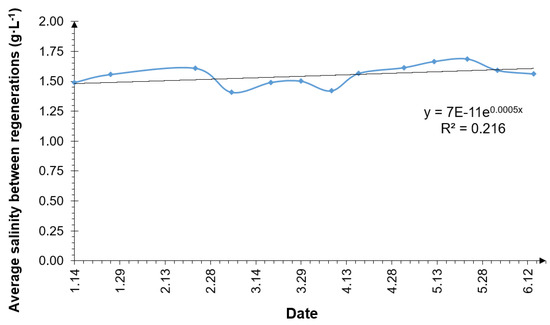
Figure 8.
Average NaCl concentration at the septic tank outflow occurring between softener regenerations.
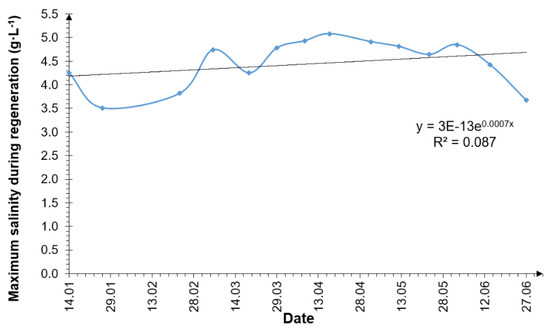
Figure 9.
Maximum NaCl concentration at the septic tank outflow during water softener regeneration.
Although the study demonstrated that the increase in NaCl concentration in the septic tank outflow was not statistically significant, a number of researchers and leading practitioners are convinced of the negative impact of the brine produced by the regeneration of the water softener exchange resin on the ability of septic tanks to settle solids and treat wastewater [27,37]. There is no doubt that the increased levels of sodium inhibit settling and increase the deflocculation of settled solids, especially in industrial and domestic WTPs [38,39]. Consequently, it can also invalidate manufacturers’ warranties on all elements of the most common technologies. Concerns regarding this issue have led areas in the United States, including the states of Massachusetts and Connecticut, to formulate legal prohibitions on discharging brine into septic tanks and instructions for other technological solutions for discharging regenerate outside of the ST [16,40].
3.2. Temperature Value on Outflow from the Septic Tank
In parallel to the salinity measurements, the temperature of the wastewater flowing into the control well, located downstream of the septic tank, was also measured. Figure 10 shows the changes in temperature and NaCl concentration over two days (measurements every 1 min). From the course of the NaCl concentration, it was concluded that the regeneration process of the water softener had started at approx. 8 a.m. (480 min), after which the NaCl concentration in the septic tank outflow reached a value of approx. 4.0 g·L−1. Meanwhile, the change in the temperature of the wastewater discharging from the septic tank (and flowing into the control well) showed a difference of approx. 10 °C, over a period of one day—such a situation generally occurs in winter. The maximum recorded temperature reached about 24 °C (in the summer) and the minimum reached lower than 2 °C (in the winter).
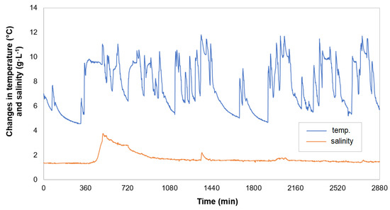
Figure 10.
Changes in the temperature and salinity of treated wastewater, during an example of two days of the winter period.
By comparing the values of the results in Figure 11a,b, which show the temperature pattern from a selected week of the summer and winter period, small temperature variations of around 2 °C per day in summer (Figure 11a) and up to 10 °C per day in winter (Figure 11b) were noted. During the winter period, the wastewater cooled down—most often during the night hours, when there was no warm wastewater inflow [37]. However, in the case of the conducted tests, after the first day, as evidenced by the graphical image in Figure 11b, there was no cooling down (in the week considered in the graph) of the wastewater in the control well. Cooling only occurred on subsequent days during the night period, when the temperature decreased to around 5 °C. The highest wastewater temperatures during the winter period occurred during the evening peak when bathing water (a large volume of wastewater with a significant temperature value) was discharged.
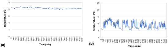
Figure 11.
Changes in temperature of the treated wastewater in sample weeks of (a) the summer period and (b) the winter period.
The temperature values obtained for the wastewater discharged from the septic tank are consistent with the temperature range (3–19 °C) reported by Pawlak et al. (2015), who showed a more significant relationship between the temperature of the wastewater in the tank at the outlet of the septic tank and the air temperature, obtaining a linear determination coefficient for this relationship R2 = 0.76 [13]. Similar values for the temperature of wastewater draining from septic tanks were reported by Bounds (1997) in his work, i.e., ranging from 10 to 23 °C [41]. On the other hand, Leverenz et al. (2010) reported monthly average temperatures in a septic tank in San Francisco (USA) that ranged from approximately 17 °C, between February and May, to 22 °C, in September, while in Quebec (Canada), temperatures ranged from 9 °C in January to 22 °C in July, and in Kansas (USA), from 7 °C in April to 18 °C in August, confirming a significant relationship between the air temperature and the wastewater temperature in septic tanks [42].
Patterson (2003) also carried out an experiment to measure the temperature of the wastewater in a septic tank, located in Australia, using a recorder with a 15 min time interval [43]. In his opinion, temperature fluctuations in the septic tank should be small and brief due to the relatively small volume of hot and cold wastewater compared to the volume of the tank. This researcher deduced that temperature changes caused by warm effluent from—for example, a shower at 38 °C or a dishwasher that runs at 60 °C—can be significant during winters, while at other times of the year, they may be small, which was confirmed by the results of field studies presented in his publication [37]. He also believes that cold water changes the temperature of wastewater during the summer, providing the example of a 1.5 °C drop in temperature due to the use of high volumes of cold water from flushing toilets and washing hands. During the 14-day study period of the four septic tanks, temperature fluctuations fell within a relatively wide range of 20 °C to 31 °C.
3.3. Hydraulic Conductivity of Soil—Semi-Technical Scale Test
On a semi-technical scale, a study was carried out to assess the hydraulic conductivity of soil exposed to sodium chloride using constructed filter columns (see Figure 4). During the course of this experiment, 84 days, i.e., 12 weeks of operation of the water softener system, working together with the septic tank, were simulated. As designed, a salt solution was injected into the second group of columns every 10 simulated days (Figure 3; 2a, b, c,). In order to assess the potential difference between the effects of the treated wastewater, brine from the grey water and water on the ground, four hydraulic conductivity tests were carried out on all columns, which were each performed on the fourth simulated day after the regeneration of the water softener.
Figure 12a–c shows the changes in height difference between the initial water level and the level after 60 min during the hydraulic conductivity tests for each group of filter columns.
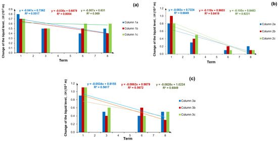
Figure 12.
Difference in height between the initial water level and the level after 60 min (∆H), for: (a) column group 1a, b, c supplied with treated wastewater, (b) column group 2a, b, c supplied with treated wastewater and brine solution periodically and (c) column group 3a, b, c supplied with tap water; terms from 1–8 represent the measurement periods after 1–8 regenerations.
The linear trends in Figure 12a–c are mostly decreasing. However, in Figure 12b, which shows the columns supplied with treated wastewater and brine, there are more leading trends. This may be due to the increased salt content of the soil. It is likely that the NaCl may have influenced the swelling of the soil and reduced the water-permeable surface area [22]. The coefficient of determination relating to the first group of columns (treated wastewater, Figure 12a) reached values above 55% in two cases (Column 1a and 1b), while it was below 10% for Column 1c. Regarding the second group of columns (treated wastewater + brine, Figure 12b), variable X had an influence of more than 80% on the value of variable Y in two cases, while the remaining third had an influence of less than 70%. The coefficient of determination R2 in the third group of columns (tap water, Figure 12c) ranged from 56% to 68%. When comparing all three column variants, it was found that for column group 2 (i.e., the column variant supplied with treated wastewater and brine), the decrease in the height difference between the initial water level and the level after 60 min (∆H), was most evident. In this case, the trend lines (Figure 12b) show the greatest decreases, while the coefficients of determination were the highest compared to the others (Figure 12a,c), with column group 1 distinguished by the lowest decrease in ∆H.
Table 1 presents the values of water level differences during hydraulic conductivity testing.

Table 1.
Summary of water level differences during hydraulic conductivity testing.
On the basis of the Shapiro–Wilk test of normality [44], it can be deduced that the distribution follows a normal distribution—there are no grounds to reject the null hypothesis p = 0.827 > α = 0.01 (p—test probability, α(n)—tabulated test coefficient for sample size n (see Figure 13)).
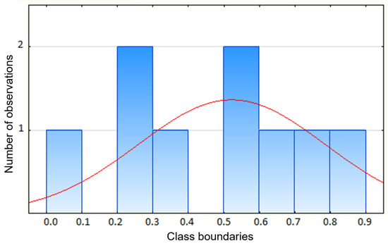
Figure 13.
Shapiro–Wilk test for the difference between the measurement after 1 regeneration and the measurement after 8 regenerations (W(α,n)—critical value for fixed α, read from the quantile tables for the Shapiro–Wilk test).
The next step was to check for the homogeneity of variance [44] in order to select an appropriate statistical test for the significance of differences between the results. A p-value of 0.787 > α = 0.05 means that, at a significance level of 0.05, there are no grounds to reject the null hypothesis of homogeneity of variance.
In order to indicate the significance of differences between the measurement after 1 regeneration and the measurement after 8 regenerations in pairs, Fisher’s test was performed. Table 2 presents the differences between the measurement of the change in the height of the liquid in the column at 60 min after 1 regeneration and the same measurement after 8 regenerations, obtained using the Fisher test carried out in Statistica 13.3 software (StatSoft Inc., 2013, Tulsa, OK, USA).
Table 2.
Comparison of the difference between the measurement after 1 regeneration and the measurement after 8 regenerations—Fisher’s test.
Based on the results presented in Table 2 at the significance level of α = 0.01, using Fisher’s test, the specific hypotheses were rejected for column pair 1–2 (because p = 0.009 < α = 0.01). At a significance level of 0.01, we found that the true differences between the measurement after one regeneration and the measurement after eight regenerations of the column pairs listed above (treated wastewater dosing option and treated wastewater dosing with brine) were significantly different. In contrast, the differences between the measurement results for column pairs 1–3 and 2–3 (i.e., comparison of the options for water supply alone and the other options) are not significantly different.
Figure 14a–c presents the estimated hydraulic conductivity (Ks) according to the Van Hoorn Formula (1) for the individual filter columns.
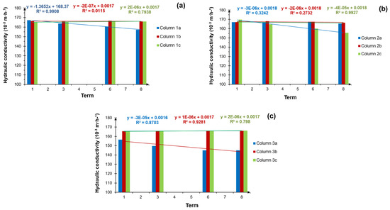
Figure 14.
Hydraulic conductivity for: (a) column group 1, supplied with treated wastewater, (b) column group 2, supplied with treated wastewater and brine solution periodically, and (c) column group 3, supplied with tap water; terms from 1–8 represent the measurement periods after 1–8 regenerations.
When analysing the effect of the grey water discharged from the water softener into the DWTPs, with reference to the results in Figure 14a–c, no significant effect was found on the deterioration of the hydraulic conductivity of the investigated soil. However, returning to Figure 12b, which shows the height difference between the initial water level and the level after 60 min for column group 2, supplied with treated wastewater and brine, it is important to recall the leading linear trends. This course of the graph, as previously mentioned, is most likely the result of increased salt content in the soil. It cannot, therefore, be excluded that, recorded at a semi-technical scale, the lack of a significant effect of grey water on changes in the hydraulic conductivity of the soil under investigation was unambiguous with the actual state. In this respect, there is a need to continue research with other parameters, including microbiological and physicochemical research.
The brine used in the regeneration process must be disposed of in a proper manner. Conventionally, it is directed to a cesspool, discharged underground into a dry well or routed through building pipes to grade level. Regardless of where it flows, brine has the potential to affect groundwater or surface water. The brine for flushing contains excess chloride, sodium, and potassium ions from regeneration salts and naturally occurring ions removed from tap water that may have been concentrated by the water softener. Particular areas of concern, as mentioned in the introduction of this paper, are high chloride concentrations [22,23].
Domestic wastewater has a high nutrient content in organic matter and macro- and micro-nutrients, especially nitrogen and phosphorus, which could favour crop production. Wastewater reuse has been practised for centuries in drylands and semi-arid countries such as Israel, Saudi Arabia, Libya, and Egypt [45]. With the growth of the closed-loop economy and environmental pressures, the disposal and management of wastewater are becoming an increasingly important research topic [46]. However, the reuse of raw wastewater in a soil application may endanger the environment through increased salinity, heavy metal contamination, densification, and the introduction of pathogens, viruses, and others [47]. The source literature describes a growing number of technologies that address the above-mentioned issues. For example, Liu et al. developed a short-term column experiment on simulating the infiltration process of wastewater in desert soil [25]. Wastewater irrigation and plant growth decreased the soil zeta potential while increasing the formation of aggregates and bacterial abundance and diversity in soil. This course of action is promising.
4. Conclusions
During the water softener regeneration in the DWTPs included in this study, a short-term maximum NaCl concentration in the treated wastewater was observed at the septic tank drainage point, ranging from 3.5 to 5.1 g·L−1, with an average value of 4.5 ± 0.5 g·L−1. The six-month research results of the average NaCl concentration at the ST outflow, conducted at a real scale, did not provide a clear position on the increase in the value of the average NaCl concentration between the regeneration periods of the WS. The data obtained systematically demonstrate a low coefficient of determination value for the trend line. Nevertheless, the increased value of the NaCl concentration after WS regeneration may have had a negative impact on the biological processes occurring in the subsequent stages of wastewater treatment. The above results, therefore, provide a basis for further research into the effects of WS treatment on the biological processes in DWTPs. In order to optimise the processes in DWTPs, further research will include the analysis of microbiological, physicochemical parameters, and the type of filter material.
The results of the hydraulic conductivity and statistical analysis, obtained from the semi-technical scale experiment, made it possible to observe differences between the filter columns supplied with treated wastewater and columns to which treated wastewater with brine was applied. The differences in the liquid height values between the columns indicate the accumulation of salt and the likelihood of its influence on the permeability and absorption of the drain due to physico-chemical changes, including the process of soil swelling and the siltation of porous structures, among others. Presumably, it is the type of soil that may have a decisive influence on the intensity of siltation of the infiltration drainage. Further studies on the effect of brine on the hydraulic conductivity of the soil for different types of soil and over a longer period of time are therefore planned.
Author Contributions
Conceptualisation, M.P.; methodology, M.P., K.Z. and S.K.; software, M.P. and R.M.; validation, S.K. and R.M.; formal analysis, A.A.P.; investigation, M.P., K.Z., S.K. and R.M.; resources, M.P., A.A.P. and K.Z.; data curation, M.P. and A.A.P.; writing—original draft preparation M.P.; writing—review and editing, M.P. and A.A.P.; visualisation, M.P. and A.A.P.; supervision, A.A.P. and K.Z.; project administration, M.P.; funding acquisition, M.P. and A.A.P. All authors have read and agreed to the published version of the manuscript.
Funding
This research was co-financed within the framework of the Polish Ministry of Science and Higher Education’s programme: “Regional Initiative Excellence” in the years 2019–2022 (No. 005/RID/2018/19), financing amount 12 000 000.00 PLN.
Institutional Review Board Statement
Not applicable.
Informed Consent Statement
Not applicable.
Conflicts of Interest
The authors declare no conflict of interest.
References
- Gallagher, J.; Gill, L.W. The Life Cycle Environmental Performance of On-Site or Decentralised Wastewater Treatment Systems for Domestic Homes. Water 2021, 13, 2542. [Google Scholar] [CrossRef]
- D’Amato, V.A.; Bahe, A.; Bounds, T.; Comstock, B.; Konsler, T.; Liehr, S.K.; Long, S.K.; Ratanaphruks, K.; Rock, C.A.; Sherman, K. Factors Affecting the Performance of Primary Treatment in Decentralized Wastewater Systems; Raport WERF 04-DEC-7; IWA Publishing: London, UK, 2008. [Google Scholar]
- Saeed, T.; Afrin, R.; Al-Muyeed, A.; Miah, J.; Jahan, H. Bioreactor septic tank for on-site wastewater treatment: Floating constructed wetland integration. J. Environ. Chem. Eng. 2021, 9, 105606. [Google Scholar] [CrossRef]
- Adhikari, J.R.; Lohani, S.P. Design, installation, operation and experimentation of septic tank—UASB wastewater treatment system. Renew. Energy 2019, 143, 1406–1415. [Google Scholar] [CrossRef]
- Pishgar, R.; Morin, D.; Young, S.J.; Schwartz, J.; Chu, A. Characterization of domestic wastewater released from ‘green’ households and field study of the performance of onsite septic tanks retrofitted into aerobic bioreactors in cold climate. Sci. Total Environ. 2021, 755, 142446. [Google Scholar] [CrossRef] [PubMed]
- Perumal, M.; Karikalacholan, S.; Parimannan, N.; Arichandran, J.; Ravi, K.S.R.; Jayapandiyan, S.; Jayakumar, S.; Mohandas, T. Integrated anaerobic-aerobic processes for treatment of high strength wastewater: Consolidated application, new trends, perspectives, and challenges. In Integrated Environmental Technologies for Wastewater Treatment and Sustainable Development; Elsevier Science: Amsterdam, The Netherlands, 2022; pp. 457–481. [Google Scholar]
- Chandra, S.; Jagdale, P.; Medha, I.; Tiwari, A.K.; Bartoli, M.; Nino, A.D.; Olivito, F. Biochar-Supported TiO2-Based Nanocomposites for the Photocatalytic Degradation of Sulfamethoxazole in Water—A Review. Toxics 2021, 9, 313. [Google Scholar] [CrossRef] [PubMed]
- Ahmad, R.; Kim, J.K.; Kim, J.H.; Kim, J. Nanostructured Ceramic Photocatalytic Membrane Modified with a Polymer Template for Textile Wastewater Treatment. Appl. Sci. 2017, 7, 1284. [Google Scholar] [CrossRef]
- De Nino, A.; Olivito, F.; Algieri, V.; Costanzo, P.; Jiritano, A.; Tallarida, M.A.; Maiuolo, L. Efficient and Fast Removal of Oils from Water Surfaces via Highly Oleophilic Polyurethane Composites. Toxics 2021, 9, 186. [Google Scholar] [CrossRef]
- Lohani, S.P.; Khanal, S.N.; Bakke, R. A simple anaerobic and filtration combined system for domestic wastewater treatment. Water-Energy Nexus (WEN) 2020, 3, 41–45. [Google Scholar] [CrossRef]
- Liu, X.; Zhang, S.; Cheng, R.; Liu, R.; Liu, Z.; Yang, Q. Effects of nZVI and Fe3O4 NPs on anaerobic methanogenesis, microbial communities and metabolic pathways for treating domestic wastewater at ambient temperature. J. Water Proc. Eng. 2022, 48, 102845. [Google Scholar] [CrossRef]
- Sanchez, L.; Carrier, M.; Cartier, J.; Charmette, C.; Heran, M.; Steyer, J.P.; Lesage, G. Enhanced organic degradation and biogas production of domestic wastewater at psychrophilic temperature through submerged granular anaerobic membrane bioreactor for energy-positive treatment. Bioresour. Technol. 2022, 353, 127145. [Google Scholar] [CrossRef]
- Pawlak, M.; Skiba, M.; Spychała, M.; Nieć, J. The investigation of density currents and rate of outflow from a septic tank. J. Ecol. Eng. 2015, 16, 103–110. [Google Scholar] [CrossRef]
- Mahon, J.M.; Jan Knappe, J.; Gill, L.W. Sludge accumulation rates in septic tanks used as part of the on-site treatment of domestic wastewater in a northern maritime temperate climate. J. Environ. Manag. 2022, 304, 114199. [Google Scholar] [CrossRef]
- Amerian, T.; Farnood, R.; Sarathy, S.; Santoro, D. Effects of total suspended solids, particle size, and effluent temperature on the kinetics of peracetic acid decomposition in municipal wastewater. Water Sci. Technol. 2019, 80, 2299–2309. [Google Scholar] [CrossRef] [PubMed]
- Toor, G.S.; Lusk, M.; Obreza, T. Onsite Sewage Treatment and Disposal Systems: An Overview. University of Florida IFAS Extension. 2011. Available online: https://edis.ifas.ufl.edu/pdffiles/SS/SS54900.pdf (accessed on 15 June 2011).
- Jowett, E.C.; Lay, R. Importance of Laminar Flow Design in Septic Tank; Waterloo Biofilter Systems: Guelph, ON, Canada, 2006. [Google Scholar]
- Parsons, S.A. The effect of domestic ion–exchange water softeners on the microbiological quality of drinking water. Water Res. 2000, 34, 2369–2375. [Google Scholar] [CrossRef]
- Lahnafi, A.; Elgamouz, A.; Jaber, L.; Tijani, N.; Kawde, A.N. NaA zeolite-clay composite membrane formulation and its use as cost-effective water softener. Microporous Mesoporous Mater. 2023, 348, 112339. [Google Scholar] [CrossRef]
- Skipton, S.O.; Dvorak, B.I.; Niemeyer, S.M. Drinking Water Treatment: Water Softening (Ion Exchange). University of Nebraska-Lincoln Extension. 2003–2014. Available online: https://www.ianrpubs.unl.edu/live/g1491/build/g1491.pdf (accessed on 9 September 2014).
- Koul, B.; Yadav, D.; Singh, S.; Kumar, M.; Song, M. Insights into the Domestic Wastewater Treatment (DWWT) Regimes: A Review. Water 2022, 14, 3542. [Google Scholar] [CrossRef]
- Ali, M.E.A. Nanofiltration process for enhanced treatment of RO brine discharge. Membranes 2021, 11, 212. [Google Scholar] [CrossRef]
- Sánchez-Aldana, D.; Ortega-Corral, N.; Rocha-Gutiérrez, B.A.; Ballinas-Casarrubias, L.; Pérez-Domínguez, E.J.; Nevárez-Moorillon, G.V.; Soto-Salcido, L.A.; Ortega-Hernández, S.; Cardenas-Félix, G.; González-Sánchez, G. Hypochlorite generation from a water softener spent brine. Water 2018, 10, 1733. [Google Scholar] [CrossRef]
- Semaha, P.; Lei, Z.; Yuan, T.; Zhang, Z.; Shimizu, K. Transition of biological wastewater treatment from flocculent activated sludge to granular sludge systems towards circular economy. Bioresour. Technol. Rep. 2023, 21, 101294. [Google Scholar] [CrossRef]
- Liu, C.; Liu, F.; Andersen, M.N.; Wang, G.; Wu, K.; Zhao, Q.; Ye, Z. Domestic wastewater infiltration process in desert sandy soil and its irrigation prospect analysis. Ecotoxicol. Environ. Saf. 2021, 208, 111419. [Google Scholar] [CrossRef]
- Gross, M.; Bounds, T. The effect of water softener backwash brine in onsite wastewater treatment systems. In Proceedings of the Eleventh Individual and Small Community Sewage Systems Conference Proceedings, Warwick, RI, USA, 20–24 October 2007; pp. 72–105. [Google Scholar]
- Higgins, M.J.; Novak, J.T. Dewatering and settling of activated sludges: The case for using cation analysis. Water Environ. Res. 1997, 69, 225–232. [Google Scholar] [CrossRef]
- Harris, S.; Tsalidis, G.; Corbera, J.B.; Gallart, J.J.E.; Tegstedt, F. Application of LCA and LCC in the early stages of wastewater treatment design: A multiple case study of brine effluents. J. Clean. Prod. 2021, 307, 127298. [Google Scholar] [CrossRef]
- Naik, B.; Pradhan, S.S.; Bagal, D.K. Mechanical characterization based on partial replacement analysis of portland pozzolana cement with industrial waste in M30 grade concrete. Int. J. Appl. Eng. Res. 2019, 14, 1–53. [Google Scholar]
- Gonzalez-Martinez, S.; Gonzalez-Barcelo, O.; Flores-Torres, C.A. Wastewater treatment in an anaerobic filter using small lava stones as filter media without temperature control. Water Sci. Technol. 2011, 63, 1188–1195. [Google Scholar] [CrossRef]
- Nieć, J.; Spychała, M. Hydraulic conductivity estimation test impact on long-term acceptance rate and soil absorption system design. Water 2014, 6, 2808–2820. [Google Scholar] [CrossRef]
- Błażejewski, R. The Sewerage of the Village; Polish Association of Sanitary Engineers and Technicians: Poznań, Poland, 2003. (In Polish) [Google Scholar]
- Norm DTU 64. Implementation of autonomous sanitation systems—Single-family houses. French and European standards (Mise en oeuvre des dispositifs d’assainissement autonome—Maisons d’habitation individuelle), 1998.
- Laak, R. Wastewater Engineering Design for Unsewered Areas, 2nd ed.; Technomic Publ. Co.: Lancaster, PA, USA, 1986. [Google Scholar]
- Kargi, F.; Dincer, A.R. Salt inhibition in biological treatment of saline wastewater in RBC. J. Environ. Eng. 1999, 125, 966–971. [Google Scholar] [CrossRef]
- Uygur, A.; Kargi, F. Salt inhibition on biological nutrient removal from saline wastewater in a sequencing batch reactor. Enzym. Microb. Technol. 2004, 34, 313–318. [Google Scholar] [CrossRef]
- Harrison, J.F.; Michaud, C.F. Home water treatment system discharges to on-site wastewater systems. Water Cond. Purific. (WC&P) 2005, 12, 34–39. [Google Scholar]
- Murthy, S.N.; Novak, J.T.; De Haas, R.D. Monitoring cations to predict and improve activated sludge settling and dewatering properties of industrial wastewaters. Water Sci. Technol. 1998, 38, 119–126. [Google Scholar] [CrossRef]
- Davis, M.L. Water and Wastewater Engineering: Design Principles and Practice; The McGraw-Hill Companies, Inc.: New York, NY, USA, 2011. [Google Scholar]
- WQRF Softened Water Benefits Study—Energy Savings (Issue VI, Article 1) In: WQA Recertification Kit. 2012. Available online: https://wqa.org/wp-content/uploads/2022/09/Article-1-Softened-Water-Benefits-Study-Vol.-VI-Copy.pdf (accessed on 12 May 2012).
- Bounds, T.R. Design and Performance of Septic Tanks. Site Characterization and Design of Onsite Septic Systems ASTM STP 901; Bedinger, M.S., Johnson, A.I., Fleming, J.S.J., Eds.; American Society for Testing Materials: Philadelphia, PA, USA, 1997. [Google Scholar]
- Leverenz, H.L.; Tchobanoglous, G.; Darby, J.L. Evaluation of Greenhouse Gas Emissions from Septic Systems; Report WERF DEC1R09; IWA Publishing: London, UK, 2010. [Google Scholar]
- Patterson, R.A. Temporal Variability of Septic Tank Effluent in Future Directions for On-site Systems: Best Management Practice. In Proceedings of the On-Site ’03 Conference, Armidale, Australia, 30 September–2 October 2003; Patterson, R.A., Jones, M.J., Eds.; Lanfax Laboratories: Armidale, Australia, 2003; pp. 305–312, ISBN 0-9579438-1-4. [Google Scholar]
- James, G.; Witten, D.; Hastie, T.; Tibshirani, R. An Introduction to Statistical Learning: With Applications in R, 2nd ed.; Springer Publishing: New York, NY, USA, 2021. [Google Scholar]
- Travis, M.J.; Wiel-Shafran, A.; Weisbrod, N.; Adar, E.; Gross, A. Greywater reuse for irrigation: Effect on soil properties. Sci. Total Environ. 2010, 408, 2501–2508. [Google Scholar] [CrossRef]
- Bolaños-Benítez, V.; McDermott, F.; Gill, L.; Knappe, J. Engineered silver nanoparticle (Ag-NP) behaviour in domestic on-site wastewater treatment plants and in sewage sludge amended-soils. Sci. Total Environ. 2020, 722, 137794. [Google Scholar] [CrossRef] [PubMed]
- Frenk, S.; Hadar, Y.; Minz, D. Resilience of soil bacterial community to irrigation with water of different qualities under Mediterranean climate. Environ. Microbiol. 2014, 16, 559–569. [Google Scholar] [CrossRef] [PubMed]


Disclaimer/Publisher’s Note: The statements, opinions and data contained in all publications are solely those of the individual author(s) and contributor(s) and not of MDPI and/or the editor(s). MDPI and/or the editor(s) disclaim responsibility for any injury to people or property resulting from any ideas, methods, instructions or products referred to in the content. |
© 2023 by the authors. Licensee MDPI, Basel, Switzerland. This article is an open access article distributed under the terms and conditions of the Creative Commons Attribution (CC BY) license (https://creativecommons.org/licenses/by/4.0/).