Abstract
In this paper, a discrete skew methodology is presented to understand the effect of skewing angle on electromagnetic torque in SynRM design. A new approach is proposed to estimate the amplitude of each torque ripple component as a function of skewing angle. The reduction factor for each harmonic component is derived in general form, allowing for the determination of overall torque ripple waveform. The validity of the proposed method is evaluated through the examination of two SynRMs, resulting in a torque ripple reduction of up to 70%. The results obtained through the use of a proposed analytical ripple reduction estimator and FEA evaluation showed good agreement. The proposed skewing technique was applied on a previously optimized triple-barrier SynRM with a positive outcome: a consistent torque ripple reduction tackling relevant harmonic components. The analysis of harmonic distribution of torque ripple is mandatory for the selection of the optimal skewing strategy when following the proposed method, with two-step skewing recommended for mostly-purely-sinusoidal torque waveforms, and multi-step skewing recommended for machines with multiple higher-magnitude harmonic components.
1. Introduction
The operating principle of Synchronous Reluctance Motors (SynRMs), shown schematically in Figure 1, is based on the anisotropy variations of different magnetic paths, present in the rotor structure, that enable the production of reluctance torque. SynRMs are singly excited machines that can achieve good torque density, high efficiency, high-speed operation, fault tolerance capability, and low cost [1,2,3,4,5], making them a promising competitor of induction machines (IM). The absence of rotor windings or rotor cage translates into zero rotor copper losses, and as a result, lower rotor temperatures and higher efficiency in comparison with IMs [6]. In addition, the absence of permanent magnets simplifies the manufacturing process and reduces the overall cost with respect to other machines for the same power. Nevertheless, these advantages come at the cost of two critical drawbacks: high torque ripple and low power factor [1,7]. If the torque ripple is not minimized by design or by control strategies, it can lead to undesired mechanical vibrations and potential acoustic noise, as well as impact the current harmonics. Moreover, in high-performance applications, low torque ripple is strictly required [8], and consequently, different techniques have been developed to reduce its magnitude as much as possible. One of the main sources of the large torque ripple in SynRM is the interaction of the spatial harmonics in the magnetic motive force, generated by stator currents, and the anisotropic rotor geometry and its features [9]. There are several different design techniques presented in the literature to reduce the torque ripple in SynRMs, and they can be divided into two main categories: (i) those that aim to modify and optimize the winding configuration and slot pole combinations [10], and (ii) those that seek to optimize the rotor structure (flux barriers), the details of its geometry, or the positioning and dimension of the iron ribs [11,12,13,14,15]. Among these techniques, skewing the stator or rotor structure is one of the most predominant [16,17,18] since it provides a reliable and straightforward solution for mitigating the torque ripple. Moreover, skewing is the most used method for suppressing torque ripple in SynRM [18].
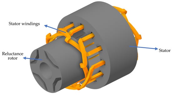
Figure 1.
Three-dimensional sketch of a one-barrier four-pole synchronous reluctance motor.
Skewing techniques can be classified into two main categories: continuous skewing and discrete skewing (also called step skewing). The first one involves rotating each lamination of the stator or rotor core in regular angular distribution, between the first and the last slice equal to the skew angle [15], as depicted in Figure 2b. This can drastically reduce torque ripple, but complicates and makes the manufacturing process more expensive since each lamination of the rotor has a different position with respect to a symmetry axis, thus requiring specific tooling. In turn, the second category, considers the division of the rotor stack into a few discrete segments, as shown in Figure 2c.
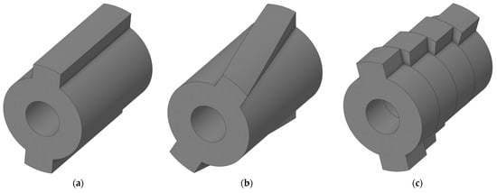
Figure 2.
Three-dimensional sketches of different types of skew: (a) reference skewless rotor, (b) continuous skew, (c) discrete skew, also called step skew.
A considerable number of studies have addressed the rotor skewing technique using the conventional one-slot-pitch skew angle. These studies can be found in references [19,20,21,22,23,24,25]. In [19], the performance of a SynRM is compared when it is operated without skewing to when the rotor is skewed by one stator tooth pitch. Reference [20] investigates the effect of rotor skewing on reducing slot harmonic torques, using a conventional skew angle of one stator slot pitch, but this reduces the average torque as well. This was confirmed in [21,22]. In [23], the equation to calculate the skew angle to suppress the stator slot harmonic component (one-slot-pitch) was presented, considering the number of slices in the calculation. The novel forced feasibility concept was introduced in [24] to improve optimization convergence and reduce overall optimization time in a SynRM design. A rotor skew was chosen as the best suited torque-ripple mitigation option by skewing the rotor at an angle of one stator slot. Recently in [25], a SynRM with salient pole rotor was continuously skewed by one stator slot pitch to improve energy conversion and reduce torque ripple. The impact of rotor skewing on torque ripple in SynRMs was analyzed in recent research [16], comparing both continuous and segmented rotor skewing. Post-optimization simulations were performed for both methods and yielded similar results, with a slight advantage to segmented rotor skewing due to the increased cost of continuous skewing. In both cases, the total skew angle was equal to one stator slot. As it may be noted from the dates of these works, the one-slot-pith skewing trend is dominant as a post-optimization process, applicable to several up-to-date machine topologies.
In turn, several papers have discussed the skewing technique for reducing torque ripple [26,27,28,29,30,31,32], but they lack information on the selection of the skew angle or the skewing parameters used. In [26], a rotor design with an asymmetric flux barrier was created to reduce torque ripple by splitting the rotor into two step-skewed parts. However, the paper does not mention the method used to determine the skew angle, which is assumed to be equal to the slot pitch. Reference [29] evaluates the suitability of SynRMs for electric traction applications. Skew is applied to reduce torque ripple by using a 2.5° mechanical skew angle between three stacks, resulting in an angle close to the slot pitch. In [30], the torque ripple was reduced by dividing the machine into three layers using step skew, but the skewing angle is not specified. A SynRM was optimized using topology optimization in [31], which increased the torque compared to a model optimized with parameters, but also increased the torque ripple. The skewing technique was used to reduce the torque ripple by dividing the rotor into two slices, but the specific skew angle and its determination method are not reported. In [32], the goal was to reduce torque ripple through rotor skewing while maintaining a power factor through optimization. The study found that the optimum mechanical skew angle across all machines was 2.5 mechanical degrees, very close to the slot pitch. All these works seem to match the one-slot-pith skewing trend.
Despite the prevalence of the slot pitch angle as the optimal skew angle in the literature, references [33,34] question its effectiveness in minimizing torque ripple. Reference [33] demonstrates that a torque ripple of less than 3.0% can be achieved by applying rotor skew. The optimum rotor skew angles ranged from 60–70% of a slot pitch angle for the 24-slot machine and 30–80% for the 36-slot machine. The analysis highlights that the ideal rotor skew angle heavily depends on both the stator configuration and the rotor topology. In [34], a comparison between continuous skewing and discrete skewing was performed over a SynRM. The results indicated that the torque ripple was significantly reduced even with two stacks, while only slightly decreasing in the average torque when high order torque harmonics were produced. Some results showed that the optimal skew angle differed from the traditional one-slot pitch, being either higher or lower, depending on the type of skew technique applied (continuous or discrete).
As a result, recent trends have been investigated to improve the efficacy of skewing in different topologies [17,35,36]. A new unconventional magnet step-skew method for permanent magnet synchronous motors (PMSM) is introduced in [17]. It involves varying both the length of the magnet and the skew angle between magnet segments, in contrast to the constant stack length and step-skew angle in conventional permanent magnet (PM) motors. A semi-finite element analysis (FEA) algorithm is developed showing improved performance compared to conventional step-skew. However, it comes with increased magnet manufacturing cost. In [35], a new method for parameterizing the flux barrier profiles of SynRMs and Permanent Magnet assisted Synchronous Reluctance Machina (PMa-SynRMs) was introduced. In order to reduce torque ripple, the skew angle is obtained through a parametric FEA analysis. A discrete rotor skewing of 4° in three-step pieces is applied, which deviates from the conventional 10° angle for a 36-slot machine based on one slot pitch. In [36], the impact of step skewing on the output torque and motor inductance in a 30-slot/four-pole SynRM configuration was examined. A comparison of step skewing was made theoretically, and the study considered the effect of two harmonic orders, but did not account for the number of steps in the skewing angle calculation. Moreover, it discovered that the average torque reduction resulting from skewing is dependent on the machine operating point.
As seen, this topic has gained increased attention in the literature. A better understanding of how the optimal skewing can be achieved at the design stage is an important factor in the sizing of a SynRM. Notwithstanding and to the best of the authors’ knowledge, this has not yet been investigated. In particular, the influence of a generalized multi-step skewing on the performance of SynRM, considering a torque ripple harmonic content approach and not the traditional one-slot-pitch skewing technique, has not been examined. This study aims to serve as an input of post-optimization processes in the design stage of SynRMs.
This article presents a comprehensive analytical expression for multi-step discrete skewing in SynRM. The method calculates a specific skew angle to eliminate a specific harmonic component and a mitigation factor to showcase the impact of skewing on each harmonic component. The use of this methodology ensures a suitable selection of the harmonic to be mitigated, and reduce the number of rotor steps required to effectively decrease the presence of dominant harmonics in the electromagnetic torque, in this manner improving the machine’s performance. The article validates the proposed approach by analyzing two SynRM designs through FEA and includes three-dimensional (3D) FEA to consider the border effect, which is not present in two-dimensional (2D) FEA. The optimal step skew angle predicted by the analytical formula closely matches both 2D and 3D FEA results. The proposed equations are evaluated for two-step, three-step, and four-step skewing, showing promising results in mitigating the selected undesired harmonics and reducing other harmonic content collaterally. In addition, an optimized triple-barrier SynRM is post-optimized by means of the proposed method.
The paper is organized as follows: Section 2 presents the selected machines, describing their dimensions and main data. Section 3 provides the details of the proposed analytical expressions to select the step angle of N-step skewing, generalized for machines with any pole count. These expressions are assessed and validated in Section 4, which summarizes the results and discussion of several case studies evaluated by means of 2D and 3D FEA. Section 5 shows a study case of the proposed approach as a post-optimization process, reducing the torque ripple of an optimized triple-barrier SynRM. Conclusions are drawn at the end of the paper summarizing the benefits of the proposed approach and its applicability to the design of SynRM.
2. Selected Machines
With the aim of providing insight into the procedures required to use the proposed N-step skewing analytical expressions, two SynRM machines are considered as a case study and assessed in this work, as presented in Figure 3a,b, respectively. Single-layer distributed windings are considered for both machines.
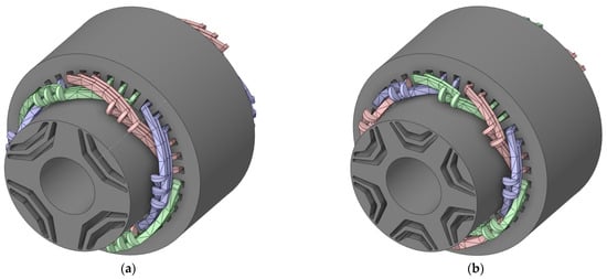
Figure 3.
Three-dimensional schematics of (a) four-pole synchronous reluctance motor with two barriers per pole; and (b) six-pole synchronous reluctance motor with two barriers per pole. Three-phase stator windings are highlighted in red, green, and blue, corresponding to each phase. Rotor in both machines is shown as an exploded view.
Several geometrical parameters of the rotor structure of SynRM can affect the different levels of a SynRM’s performance. There are several design guidelines established in the literature to choose the number of flux barriers and poles. The number of parameters increases exponentially as the number of flux barriers per pole and pole pairs increase. SynRM is designed to maximize d-axis inductance and minimize q-axis inductance, as this ensures that the machine’s saliency ratio is large enough for the machines to achieve the required torque performance. On the one hand, to obtain a good saliency ratio, a small number of pole pairs is preferred, and the literature recommends adopting two- or three-pole pairs [37]. On the other hand, the optimum number of flux barriers is defined according to the number of stator slots. In the case of a 36-slot machine, some authors do not encourage to adopt more than three flux barriers. A greater number of barriers could jeopardize the mechanical integrity of the rotor or make the design process more complex [3,38].
Therefore, in this paper, two machines with two- and three-pole pairs are considered, and each pole features two barriers. The common data for all machines are presented in Table 1.

Table 1.
Main data of the selected machines.
3. Analytical Method Derivation for Discrete Skewing
The main period of torque ripple of three-phase winding machines is 60 electrical degrees [39], which therefore dictates the period of the torque ripple harmonic of order v, derived in electrical degrees by:
The aim of the discrete skewing is to consider N machine slices, rotated with respect to each other by a specific angle, so that each slice contributes to different torque harmonics that will ultimately modulate the torque waveform. This superposition has to be adjusted with the aim of mitigating undesired harmonic components of the resulting torque waveform. The -th order harmonic of the torque ripple can be expressed as a term of the Fourier series expansion of the electromagnetic torque as:
where is the amplitude of the -th harmonic of the torque ripple, is the rotor position in electrical degrees, is the phase shift of the torque waveform, and ...
In this sense, and following the concept of balanced multiphase systems, if the -th harmonic of the torque ripple wants to be mitigated, then the electrical angle between each one of the N slices of the machine is proposed as:
For example, if a two-step skew is adopted, then the machine rotor will be comprised of two halves, each one contributing with torque waveforms that are shifted one with respect to the other. If the electrical shift is , then the positive semi-cycles of the -th harmonic of the torque ripple of one half of the rotor will compensate the negative semi-cycles of the other half, hence mitigating the undesired component.
The electrical angle between the N slices of the machine is translated into the skew angle (), which corresponds to the mechanical angle in which two consecutive rotor slices are rotated one with respect to the other so as to mitigate the -th order harmonic of the torque ripple (Equation (4)).
In Figure 4, the proposed methodology is schematized, comprising the decomposition of the electromagnetic torque waveform in harmonic components, the selection of a high-magnitude undesired component, and the calculation of to mitigate that undesired harmonic depending on the adopted number of slides N.
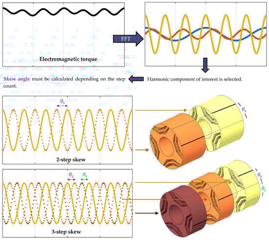
Figure 4.
Schematics of the proposed methodology to calculate the skew angle to mitigate a selected harmonic of order . Two-step and three-step discrete skew are presented, although the method can be used for any number of slides.
Considering the proposed skew angle, Equation (2) can be expressed in terms of a sum of the contributions of the N slices of the machine as
The resulting reduction on each component of the torque ripple, considering idealized conditions and electromagnetic independency between adjacent slices can be obtained by means of the phasorial representation and consequent analysis of Equation (5). Then:
In consequence, the magnitude of the -th harmonic of the torque ripple after applying discrete skewing following the design guidelines of Equations (3) and (4) can be expressed as
Finally, a skew reduction factor () can be devised by obtaining the ratio between Equations (2) and (8), derived by:
This factor is meant to be used after the calculation of the skew angle as per Equation (4), and it allows for estimating the resulting amplitude of each torque ripple component (of order v) after applying the skew. Simplified equations for and 4 are provided in the following section, which are further verified and analyzed by means of 2D and 3D finite element analysis.
4. Results and Discussion: Finite Element Validation
This section shows the results obtained by applying the analytical method described in Section 3 for both four-pole and six-pole SynRMs. In order to provide the results in a clear fashion, this section is divided into four subsections. The first presents the machine evaluations without considering any type of skew, hereby called skewless machines; and the following three sections address machines with different slide number ( and ). All the results are obtained by means of 2D and 3D FEA simulations carried out in the commercial package ANSYS Electronic Desktop. The simulation time was chosen to evaluate a whole period of the machine’s torque ripple.
4.1. FEA Evaluation Original Designs (Skewless Machines)
Figure 5 presents the electromagnetic torque waveform and spatial harmonic spectrum of both the four-pole and the six-pole SynRMs. Both 2D and 3D results are shown for comparison. From the results, the evaluation of the 2D and 3D models provide similar values, showing expected small differences, in accordance with the findings of [40]. The harmonic components of the electromagnetic torque for each machine are detailed in Figure 5b,d for the four-pole and six-pole machines, respectively. As expected, the largest harmonic component in both designs corresponds to the one generated by the stator slotting effect. Specifically, the highest magnitude harmonic of the four-pole machine corresponds to , and that of the six-pole machine corresponds to . Therefore, and according to the methodology proposed in Section 3, for the four-pole SynRM and for the six-pole machine. Table 2 shows the skew angle that should be considered to discrete skew the machine according to Equation 4, depending on the desired step number and aiming to mitigate the highest magnitude harmonic component. The following sections evaluate the impact of the proposed skew methodology on mitigating torque ripple for and .
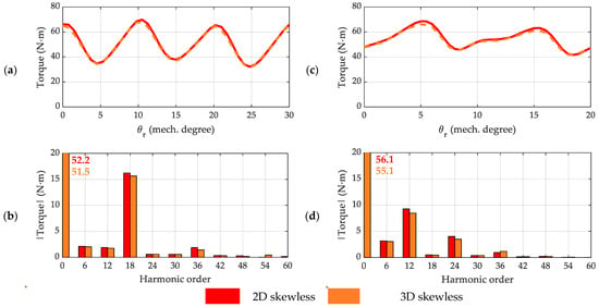
Figure 5.
Electromagnetic torque waveform and spectrum of a skewless reference machine: (a) torque waveform of four-pole machine with two barriers per pole; (b) torque spatial harmonic content of four-pole machine with two barriers per pole; (c) torque waveform of six-pole machine with two barriers per pole; (d) torque spatial harmonic content of six-pole machine with two barriers per pole. Additionally, 2D and 3D simulation results are compared.
Table 2.
Skew angle to reduce a specific electromagnetic torque harmonic order by discrete skew.
4.2. Evaluation of Torque Ripple Reduction by Means of Two-Step Discrete Skew
The comparison of the electromagnetic torque for the four-pole and six-pole machine is shown in Figure 6 when two-step skewing is applied. It can be observed that there is a significant reduction in the harmonic torque component to be mitigated, to approximately 10% of its original value.
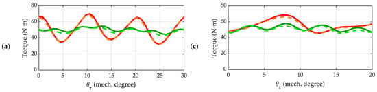
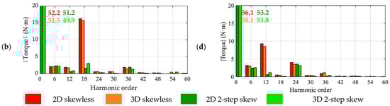
Figure 6.
Comparison of electromagnetic torque waveform and harmonic content of a skewless machine vs. two-step skewed machine: (a) torque waveform of four-pole machine with two barriers per pole; (b) torque spatial harmonic content of four-pole machine with two barriers per pole; (c) torque waveform of six-pole machine with two barriers per pole; (d) torque spatial harmonic content of six-pole machine with two barriers per pole. The 2D and 3D simulation results are compared.
This agrees with the estimations obtained from the reduction factor proposed in Equation (9), which can be simplified when evaluating to:
According to Equation (10), the reduction of the main component of the electromagnetic torque (which has order ) should be maximum (). The difference lies in the fact that Equation (9) considers magnetically independent rotor slices, neglecting their interaction. Regardless of this, a significant reduction was observed in other harmonic components. In addition, for the four-pole machine it was found that the torque ripple harmonic component with was also reduced to ~45% of its original value, whilst other relevant harmonics of order and were not significantly affected. This agrees with the estimated reduction factor proposed in Equation (10), since , and . In turn, for the six-pole machine it was observed that the relevant torque ripple harmonic component with was slightly reduced (to 87% of the original value), and that other relevant harmonics of order and were reduced to 77% and 14% of their original magnitude, respectively. This agrees with the estimated reduction factor proposed in Equation (10), since , and . In addition, the trend of other less relevant harmonic components of both machines matches closely with the estimations of Equation (10). These findings are summarized in Table 3.
Table 3.
Torque ripple harmonic component reduction as a result of two-step skewing. The 3D results were considered and relevant harmonic components analyzed.
As an overall result of the discrete two-step skewing, the peak-to-peak value of the torque ripple was reduced. Table 4 summarizes the torque ripple as a percentage of the mean torque for the 2D and 3D simulation results, respectively. The torque ripple reduction is greater than 70% for the four-pole machine and up to 55% for the six-pole design, and an expected slight reduction of the average torque was also obtained.
Table 4.
Average torque and torque ripple comparison when applying two-step skewing, by means of 2D and 3D FEA simulations.
In this specific case, it can be observed that the 3D evaluation shows worse results than the 2D assessment, since in the 3D the ripple reduction is lower, and the mean torque reduction is increased, with respect to the 2D simulations. This can be ascribed to the fact that 2D simulations on ANSYS consider each slice of the machine as independent machines, when discrete skewing is applied, and the interface between slices is not taken into account, resulting in an idealization of the problem. On the other hand, the 3D simulation evaluates the rotor as a whole unit comprised of physically rotated slices, hence considering effects within the adjacent slices interface. This is further addressed in Section 4.4.
4.3. Evaluation of Torque Ripple Reduction by Means of Three-Step Discrete Skew
The comparison of the electromagnetic torque for the four-pole and six-pole machine is shown in Figure 7 when adopting a three-step discrete skew strategy.
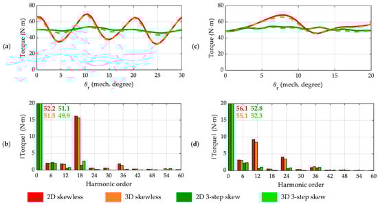
Figure 7.
Comparison of electromagnetic torque waveform and harmonic content of skewless machine vs. three-step skewed machine: (a) torque waveform of four-pole machine with two barriers per pole; (b) torque spatial harmonic content of four-pole machine with two barriers per pole; (c) torque waveform of six-pole machine with two barriers per pole; (d) torque spatial harmonic content of six-pole machine with two barriers per pole. The 2D and 3D simulation results are compared.
As in the case of the two-step skewing, there is a significant reduction of up to 93% of the highest magnitude harmonic component of the torque ripple. This is in accordance with the reduction factor derived in Equation (9), further simplified for cases with as per:
According to Equation (11), the reduction of the highest magnitude component of the electromagnetic torque, when , is maximum (). Additionally, for the four-pole machine it was found that the torque ripple harmonic components with and were reduced to ~45% and ~6% of their original value, respectively, whilst the other relevant harmonic of order was not significantly affected. This agrees with the reduction factor proposed in Equation (11) for , since , and . On the other hand, for the six-pole machine it was observed that the harmonic components with and were reduced to ~70% and ~12% of their original value, respectively, whilst the harmonic of order was not visibly reduced. This agrees with the values provided by Equation (11), since , and . Although they were not relevant contributors, the trend of other harmonic components of both machines were in good agreement with the expression presented in Equation (11). These findings are summarized in Table 5.
Table 5.
Torque ripple harmonic component reduction as a result of three-step skewing. The 3D results are considered and the relevant harmonic components analyzed.
As a result of the discrete three-step skewing, the peak-to-peak value of the torque ripple was considerably reduced. Table 6 presents the obtained mean torque and torque ripple (as a percentage of the mean torque) for the 2D and 3D simulations, respectively. It may be noted that the torque ripple reduction is greater than 75% in both analyzed designs and there is an expected slight reduction in the average torque.
Table 6.
Average torque and torque ripple comparison when applying three-step skewing, by means of 2D and 3D FEA simulations.
Similar to the case of two-step skewing, it can be appreciated that the 3D evaluation shows a worse outcome than the 2D assessment, since a lower ripple reduction and a higher mean torque reduction were achieved.
4.4. Evaluation of Torque Ripple Reduction by Means of Four-Step Discrete Skew
The comparison of the electromagnetic torque for the four-pole and six-pole machine is shown in Figure 8 when four-step skewing is applied.
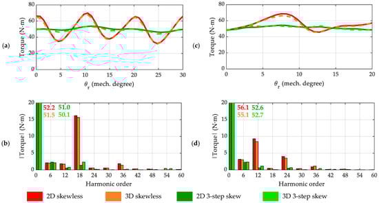
Figure 8.
Comparison of electromagnetic torque waveform and harmonic content of skewless machine vs. four-step skewed machine: (a) torque waveform of four-pole machine with two barriers per pole; (b) torque spatial harmonic content of four-pole machine with two barriers per pole; (c) torque waveform of six-pole machine with two barriers per pole; (d) torque spatial harmonic content of six-pole machine with two barriers per pole. The 2D and 3D simulation results are compared.
It can be observed that there is a significant reduction in the harmonic torque component to be mitigated, approximately 10% of its original magnitude, to a similar extent to the two-step and three-step skewing. This is in agreement with the estimations obtained from the reduction factor proposed in Equation (9), which, for the specific case of , can be simplified to:
Based on Equation (12), the reduction of the highest magnitude component of the electromagnetic torque, when , is maximum (). Additionally, for the four-pole machine it was found that the torque ripple harmonic components with and were reduced to ~35% and ~5% of their original value, respectively, whilst the other relevant harmonic of order was not affected. This is in agreement with the reduction factor proposed in Equation (12) for , since , and . On the other hand, for the six-pole machine, it was observed that the harmonic components with , and were reduced to ~74%, ~12% and ~6% of their original value, respectively. This is in agreement with the values provided by Equation (12), since , and . Although they are not relevant contributors, the trend of other harmonic components of both machines are in good agreement with the expression presented in Equation (12). A summary of these results is presented in Table 7.
Table 7.
Torque ripple harmonic component reduction as a result of three-step skewing. The 3D results are considered, and relevant harmonic components analyzed.
Four-step skewing resulted in a severe torque ripple reduction, as summarized in Table 8, which presents the results obtained by means of the 2D and 3D evaluations, respectively. The torque ripple reduction was greater than 75% in both analyzed designs and there was an expected slight reduction of the average torque.
Table 8.
Average torque and torque ripple comparison when applying four-step skewing, by means of 2D and 3D FEA simulations.
Similar to the two-step and three-step skewing cases, it may be appreciated that the 3D evaluation shows a worse outcome than the 2D assessment, since a lower ripple reduction and a higher mean torque reduction were achieved. Nevertheless, the 2D and 3D results were very similar; for this reason, assessing the proposed skew technique by means of 2D simulations as a preliminary stage design can be recommended.
It is possible to observe that, when N = 2 and N = 3 are compared, there is a considerable improvement in the reduction of the torque ripple, and the behavior is different for N = 3 and N = 4, where the reduction is the same. For all cases, N = 2, N = 3 and N = 4, the average torque remains relatively constant. Therefore, when assessing close-to-purely-sinusoidal electromagnetic torque waveforms in a SynRM, two-step skew may then be sufficient as a single ripple component. Conversely, if there are several preponderant harmonic components, then it is worth taking a multi-step skewing approach, to mitigate multiple harmonics at once. A study case is addressed in Section 5 covering this issue.
Consequently, it is necessary to correctly analyze the harmonic distribution of the electromagnetic torque to properly choose N, since increasing the number of steps does not always guarantee a significant reduction in torque ripple and could lead to other different manufacturing costs.
5. Study Case: Optimized SynRM for Minimum Ripple Torque
A 36-slot, six-pole, three-barrier SynRM was selected as the case study for this section. The aim was to show the applicability of the proposed method to an optimized machine, with the particularity that its torque ripple harmonic content does not have a predominant component. The machine design was optimized using ANSYS commercial software, including Electronic Desktop for electromagnetic analysis, DesignModeler for geometry parameterization, and Workbench for optimization. The optimization process was conducted using a combination of multi-objective genetic algorithms (MOGA) and FEA simulations. During the optimization process, the machine was supplied with a current of 20 A/mm2, which is approximately three times the rated current listed in Table 9. This answers to the known fact that selecting a current between two and three times the rated current can improve the insensitivity of torque ripple to load variations [41].
Table 9.
Main data of the study-case machine subject to optimization.
The objective functions were set to minimize torque ripple, maximize power factor, and maintain average torque above a specified value. The primary constraint during optimization was to keep the machine’s insulation ratio within the defined limits of 0.35 to 0.45, as per the literature [42]. Geometric constraints were established to ensure feasible rotor geometries and to prevent errors or unrealistic solutions during optimization. The upper and lower limits for the rotor’s geometrical parameters (objective variables) were properly defined.
The optimization results are presented in Figure 9. The optimal design was selected based on a trade-off between average torque and torque ripple, as it is not possible to achieve the lowest torque ripple and highest average torque simultaneously. In this case, the machine with the lowest torque ripple was selected.
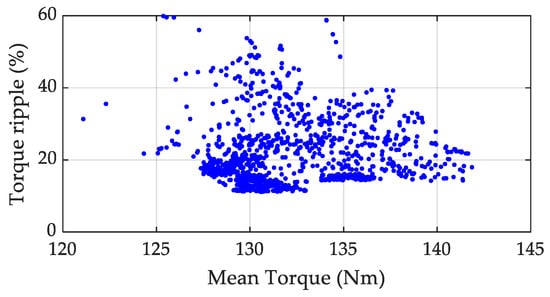
Figure 9.
Designs obtained from the optimization process. The current was fixed to ~20 A/mm2 and the current angle was defined in the optimization algorithm for MTPA.
To choose a suitable skew angle for reducing the torque ripple to acceptable values, a FFT was performed on the electromagnetic torque for one period of the torque ripple, as described in Section 3. The harmonic components of both designs under different load conditions are shown in Figure 10.
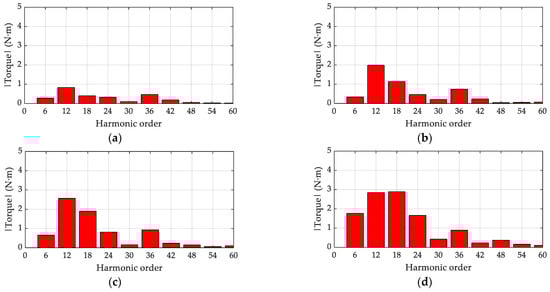
Figure 10.
Harmonic components of the electromagnetic torque for the optimum design: (a) current density 5 ; (b) current density 7.5 ; (c) current density 10 ; (d) current density 12.5 .
From Figure 10, it can be noted that, when the current density is below 10 A/mm2, the second harmonic is predominant, which is mainly related to stator slotting. When the current density is above 10 A/mm2, the third harmonic instead is predominant, which could render traditional methods useless based on mitigating the contribution of slotting effect on the torque ripple. In consequence, a customized skew angle is calculated from the proposed methodology, summarized in Table 10. This analysis considered the first, second, and third harmonics for mitigation using two-step, three-step, four-step, and five-step skewing.
Table 10.
Skew angle to reduce a specific harmonic component of the electromagnetic torque.
From Figure 10 it may be noted that some torque ripple harmonics get significantly larger as the current density increases, so it is desirable that the skewing technique used reduces these harmonics. The mitigation factor defined by Equation (9) can be used to estimate the reduction of each harmonic component. Table 11, Table 12 and Table 13 report the mitigation factor when the skew is applied to the first, second, and third harmonics, respectively.
Table 11.
Value of the mitigation factor when the sixth harmonic component is selected to reduce (.
Table 12.
Value of the mitigation factor when the 12th harmonic component is selected to reduce (.
Table 13.
Value of the mitigation factor when the 18th harmonic component is selected to reduce (.
The analysis shows that the best option for applying skew is to mitigate the first harmonic using a five-step skew. This theoretically eliminates the harmonic components, but in practice, this translates into a considerable harmonic reduction. Figure 11 shows the harmonic components of the optimal design with a five-step skew applied.
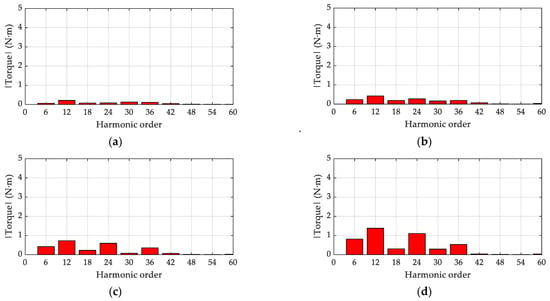
Figure 11.
Harmonic components of the electromagnetic torque for the optimum design applying five-step skewing: (a) current density 5 ; (b) current density 7.5 ; (c) current density 10 ; (d) current density 12.5 .
The result of applying this skewing techniques translates into a ripple reduction of up to 65%. Considerable differences can be appreciated when analyzing the response of this optimized machine and the machines evaluated in Section 4. For the case of the optimized machine, several harmonic components contributed to torque ripple, the reason for which a multi-step skewing was best suited from an electromagnetic perspective. In contrast, the machines addressed in Section 4 had a predominant torque ripple harmonic component, which could be handled by a two-step skewing.
6. Conclusions
In this paper, an in-depth analysis of discrete-skew methodology was investigated, and an approach proposed to better understand the effect of the skewing angle and its determination during the design phase of SynRM. Following a literature review discussing the topic, the reduction factor for each harmonic component was introduced and derived in general form to estimate the resulting amplitude of each torque ripple component as a function of the skew. As a result, the overall torque ripple waveform was estimated considering the reduction of each harmonic component.
To assess the validity of the proposed method, two SynRMs were evaluated and a torque ripple reduction of up to 70% was obtained. The outcomes from the analytical expressions and FEA evaluation showed good agreement. Moreover, the proposed harmonic component reduction factor showed promising results, being able to roughly estimate the reduction of specific harmonic components of the torque ripple. The proposed skewing technique was used to mitigate the torque ripple on a previously optimized triple-barrier SynRM with acceptable results: a 65% ripple reduction was observed from 3D FEA simulations results.
By analyzing the harmonic distribution of the torque ripple, the best skewing strategy can be selected as an input of the proposed skewing technique: for mostly-purely-sinusoidal torque waveforms, a two-step or three-step skewing is advised, whilst for machines that have multiple high-magnitude harmonic components, a multi-step skewing can be recommended.
Author Contributions
Conceptualization; methodology; software; validation; formal analysis; writing—original draft preparation, C.G. and C.M.; writing—review and editing, J.A.T. and M.D.; visualization, C.G. and C.M.; supervision, J.A.T. and M.D.; funding acquisition, J.A.T. All authors have read and agreed to the published version of the manuscript.
Funding
This research was funded in part by the Agencia Nacional de Investigación y Desarrollo (ANID), Chile through grant ANIDPFCHA/Doctorado Nacional/2020-21200527, grant ANID-PFCHA/Doctorado Nacional/2020-21200350, project FONDECYT REGULAR #1201667, and project FONDEF ID21I10099.
Institutional Review Board Statement
Not applicable.
Informed Consent Statement
Not applicable.
Data Availability Statement
Data are contained within the article.
Conflicts of Interest
The authors declare no conflict of interest.
References
- Naseer, M.U.; Kallaste, A.; Asad, B.; Vaimann, T.; Rassõlkin, A. Analytical modelling of synchronous reluctance motor including non-linear magnetic condition. IET Electr. Power Appl. 2022, 16, 511–524. [Google Scholar] [CrossRef]
- Ibrahim, M.N.F.; Abdel-Khalik, A.S.; Rashad, E.M.; Sergeant, P. An Improved Torque Density Synchronous Reluctance Machine With a Combined Star–Delta Winding Layout. IEEE Trans. Energy Convers. 2018, 33, 1015–1024. [Google Scholar] [CrossRef]
- Tawfiq, K.B.; Ibrahim, M.N.; El-Kholy, E.E.; Sergeant, P. Performance Improvement of Synchronous Reluctance Machines—A Review Research. IEEE Trans. Magn. 2021, 57, 1–11. [Google Scholar] [CrossRef]
- Wang, B.; Wang, J.; Sen, B.; Griffo, A.; Sun, Z.; Chong, E. A Fault-Tolerant Machine Drive Based on Permanent Magnet-Assisted Synchronous Reluctance Machine. IEEE Trans. Ind. Appl. 2018, 54, 1349–1359. [Google Scholar] [CrossRef]
- Villani, M.; Fabri, G.; Credo, A.; Di Leonardo, L.; Collazzo, F.P. Line-Start Synchronous Reluctance Motor: A Reduced Manufacturing Cost Avenue to Achieve IE4 Efficiency Class. IEEE Access 2022, 10, 100094–100103. [Google Scholar] [CrossRef]
- Ozcelik, N.G.; Dogru, U.E.; Imeryuz, M.; Ergene, L.T. Synchronous Reluctance Motor vs. Induction Motor at Low-Power Industrial Applications: Design and Comparison. Energies 2019, 12, 2190. [Google Scholar] [CrossRef]
- Fratta, A.; Toglia, G.P.; Vagati, A.; Villata, F. Ripple evaluation of high-performance synchronous reluctance machines. IEEE Ind. Appl. Mag. 1995, 1, 14–22. [Google Scholar] [CrossRef]
- Zhao, W.; Sun, Y.; Ji, J.; Ren, Z.; Song, X. Phase Shift Technique to Improve Torque of Synchronous Reluctance Machines With Dual M-Phase Windings. IEEE Trans. Ind. Electron. 2021, 69, 5–17. [Google Scholar] [CrossRef]
- Liang, J.; Dong, Y.; Sun, H.; Liu, R.; Zhu, G. Flux-Barrier Design and Torque Performance Analysis of Synchronous Reluctance Motor with Low Torque Ripple. Appl. Sci. 2022, 12, 3958. [Google Scholar] [CrossRef]
- Wang, B.; Wang, J.; Griffo, A.; Sen, B. Experimental assessments of a triple redundant nine-phase fault-tolerant PMA SynRM drive. IEEE Trans. Ind. Electron. 2017, 66, 772–783. [Google Scholar] [CrossRef]
- Sanada, M.; Hiramoto, K.; Morimoto, S.; Takeda, Y. Torque ripple improvement for synchronous reluctance motor using an asymmetric flux barrier arrangement. IEEE Trans. Ind. Appl. 2004, 40, 1076–1082. [Google Scholar] [CrossRef]
- Credo, A.; Villani, M.; Popescu, M.; Riviere, N. Application of Epoxy Resin in Synchronous Reluctance motors with fluid-shaped barriers for e mobility. IEEE Trans. Ind. Appl. 2021, 57, 6440–6452. [Google Scholar] [CrossRef]
- Bianchi, N.; Bolognani, S.; Bon, D.; Pre, M.D. Rotor flux-barrier design for torque ripple reduction in synchronous reluctance motors. In Proceedings of the Conference Record of the 2006 IEEE Industry Applications Conference Forty-First IAS Annual Meeting, Tampa, FL, USA, 8–12 October 2006; pp. 1193–1200. [Google Scholar]
- Gallardo, C.; Tapia, J.A.; Degano, M.; Mahmoud, H.; Hoffer, A.E. Rotor Asymmetry Impact on Synchronous Reluctance Machines Performance. In Proceedings of the 2022 International Conference on Electrical Machines (ICEM), Valencia, Spain, 5–8 September 2022; pp. 848–854. [Google Scholar]
- Ferrari, S.; Armando, E.; Pellegrino, G. Torque Ripple Minimization of PM-assisted Synchronous Reluctance Machines via Asymmetric Rotor Poles. In Proceedings of the 2019 IEEE Energy Conversion Congress and Exposition (ECCE), Baltimore, MD, USA, 29 September–03 October 2019; pp. 4895–4902. [Google Scholar]
- Ban, B.; Stipetic, S. Systematic Metamodel-Based Optimization Study of Synchronous Reluctance Machine Rotor Barrier Topologies. Machines 2022, 10, 712. [Google Scholar] [CrossRef]
- Ocak, O.; Aydin, M. An Innovative Semi-FEA Based, Variable Magnet-Step-Skew to Minimize Cogging Torque and Torque Pulsations in Permanent Magnet Synchronous Motors. IEEE Access 2020, 8, 210775–210783. [Google Scholar] [CrossRef]
- Xu, M.; Liu, G.; Chen, Q.; Ji, J.; Zhao, W. Design and optimization of a fault tolerant modular permanent magnet assisted synchronous reluctance motor with torque ripple minimization. IEEE Trans. Ind. Electron. 2020, 68, 8519–8530. [Google Scholar] [CrossRef]
- Vagati, A.; Canova, A.; Chiampi, M.; Pastorelli, M.; Repetto, M. Design refinement of synchronous reluctance motors through finite-element analysis. IEEE Trans. Ind. Appl. 2000, 36, 1094–1102. [Google Scholar] [CrossRef]
- Bomela, X.B.; Kamper, M.J. Effect of stator chording and rotor skewing on performance of reluctance synchronous machine. IEEE Trans. Ind. Appl. 2002, 38, 91–100. [Google Scholar] [CrossRef]
- Hamiti, T.; Lubin, T.; Rezzoug, A. A Simple and Efficient Tool for Design Analysis of Synchronous Reluctance Motor. IEEE Trans. Magn. 2008, 44, 4648–4652. [Google Scholar] [CrossRef]
- Wang, Y.; Ionel, D.M.; Rallabandi, V.; Jiang, M.; Stretz, S.J. Large-Scale Optimization of Synchronous Reluctance Machines Using CE-FEA and Differential Evolution. IEEE Trans. Ind. Appl. 2016, 52, 4699–4709. [Google Scholar] [CrossRef]
- Juergens, J.; Fricassè, A.; Marengo, L.; Gragger, J.; De Gennaro, M.; Ponick, B. Innovative design of an air cooled ferrite permanent magnet assisted synchronous reluctance machine for automotive traction application. In Proceedings of the 2016 XXII International Conference on Electrical Machines (ICEM), Lausanne, Switzerland, 4–7 September 2016; pp. 803–810. [Google Scholar]
- Ban, B.; Stipetic, S.; Jercic, T. Minimum Set of Rotor Parameters for Synchronous Reluctance Machine and Improved Optimization Convergence via Forced Rotor Barrier Feasibility. Energies 2021, 14, 2744. [Google Scholar] [CrossRef]
- Bernard, N.; Dang, L.; Moreau, L.; Bourguet, S. A Pre-Sizing Method for Salient Pole Synchronous Reluctance Machines with Loss Minimization Control for a Small Urban Electrical Vehicle Considering the Driving Cycle. Energies 2022, 15, 9110. [Google Scholar] [CrossRef]
- Bianchi, N.; Bolognani, S.; Bon, D.; Pre, M.D. Rotor Flux-Barrier Design for Torque Ripple Reduction in Synchronous Reluctance and PM-Assisted Synchronous Reluctance Motors. IEEE Trans. Ind. Appl. 2009, 45, 921–928. [Google Scholar] [CrossRef]
- Bianchi, N.; Fornasiero, E.; Carraro, E.; Bolognani, S.; Castiello, M. Electric vehicle traction based on a PM assisted synchronous reluctance motor. In Proceedings of the 2014 IEEE International Electric Vehicle Conference (IEVC), Florence, Italy, 17–19 December 2014. [Google Scholar]
- Lazari, P.; Wang, J.; Sen, B. 3-D Effects of Rotor Step-Skews in Permanent Magnet-Assisted Synchronous Reluctance Machines. IEEE Trans. Magn. 2015, 51, 8112704. [Google Scholar] [CrossRef]
- Hofer, M.; Schroedl, M. Comparison of a flux barrier and a salient pole synchronous reluctance machine for high rotational speeds in electric traction applications. In Proceedings of the 2017 20th International Conference on Electrical Machines and Systems (ICEMS), Sydney, NSW, Australia, 11–14 August 2017; pp. 1–6. [Google Scholar]
- Lee, T.-H.; Lee, J.-H.; Yi, K.-P.; Lim, D.-K. Optimal Design of a Synchronous Reluctance Motor Using a Genetic Topology Algorithm. Processes 2021, 9, 1778. [Google Scholar] [CrossRef]
- Lee, T.-H.; Lim, D.-K.; Moon, K.-Y.; Jeon, K.-W. Topology Optimization Combined with a Parametric Algorithm for Industrial Synchronous Reluctance Motor Design. Processes 2022, 10, 746. [Google Scholar] [CrossRef]
- Baziruwiha, J.-C.; Kamper, M.J.; Botha, S. High Pole Number Epoxy-Casted Rotor Reluctance Synchronous Wind Generator. In Proceedings of the 2022 IEEE Energy Conversion Congress and Exposition (ECCE), Detroit, MI, USA, 9–13 October 2022; pp. 1–8. [Google Scholar]
- Howard, E.; Kamper, M.J.; Gerber, S. Asymmetric Flux Barrier and Skew Design Optimization of Reluctance Synchronous Machines. IEEE Trans. Ind. Appl. 2015, 51, 3751–3760. [Google Scholar] [CrossRef]
- Hubert, T.; Reinlein, M.; Kremser, A.; Herzog, H.-G. Torque ripple minimization of reluctance synchronous machines by continuous and discrete rotor skewing. In Proceedings of the 2015 5th International Electric Drives Production Conference (EDPC), Nuremberg, Germany, 15–16 September 2015; pp. 1–7. [Google Scholar]
- Korman, O.; Nardo, M.D.; Degano, M.; Gerada, C. A Novel Flux Barrier Parametrization for Synchronous Reluctance Machines. IEEE Trans. Energy Convers. 2022, 37, 675–684. [Google Scholar] [CrossRef]
- Islam, M.S.; Shrestha, A.; Islam, M. Effect of Step Skew in Synchronous Reluctance Machines for High Performance Applications. In Proceedings of the 2022 IEEE Energy Conversion Congress and Exposition (ECCE), Detroit, MI, USA, 9–13 October 2022; pp. 1–6. [Google Scholar]
- Cai, S.; Hao, H.; Jin, M.-J.; Shen, J.-X. A simplified method to analyze synchronous reluctance machine. In Proceedings of the 2016 IEEE Vehicle Power and Propulsion Conference (VPPC), Hangzhou, China, 17–20 October 2016; pp. 1–6. [Google Scholar]
- Ibrahim, M.N.F.; Sergeant, P.; Rashad, E. Simple design approach for low torque ripple and high output torque synchronous reluctance motors. Energies 2016, 9, 942. [Google Scholar] [CrossRef]
- Bianchi, N.; Degano, M.; Fornasiero, E. Sensitivity Analysis of Torque Ripple Reduction of Synchronous Reluctance and Interior PM Motors. IEEE Trans. Ind. Appl. 2015, 51, 187–195. [Google Scholar] [CrossRef]
- Fitouri, M.; Bensalem, Y.; Abdelkrim, M.N. Comparison Between 2D and 3D Modeling of Permanent Magnet Synchronous Motor Using FEM Simulations. In Proceedings of the 2020 17th International Multi-Conference on Systems, Signals & Devices (SSD), Monastir, Tunisia, 20–23 July 2020; pp. 681–685. [Google Scholar]
- Cupertino, F.; Pellegrino, G.; Gerada, C. Design of synchronous reluctance motors with multiobjective optimization algorithms. IEEE Trans. Ind. Appl. 2014, 50, 3617–3627. [Google Scholar] [CrossRef]
- Degano, M.; Murataliyev, M.; Shuo, W.; Barater, D.; Buticchi, G.; Jara, W.; Bianchi, N.; Galea, M.; Gerada, C. Optimised Design of Permanent Magnet Assisted Synchronous Reluctance Machines for Household Appliances. IEEE Trans. Energy Convers. 2021, 4, 3084–3095. [Google Scholar] [CrossRef]


Disclaimer/Publisher’s Note: The statements, opinions and data contained in all publications are solely those of the individual author(s) and contributor(s) and not of MDPI and/or the editor(s). MDPI and/or the editor(s) disclaim responsibility for any injury to people or property resulting from any ideas, methods, instructions or products referred to in the content. |
© 2023 by the authors. Licensee MDPI, Basel, Switzerland. This article is an open access article distributed under the terms and conditions of the Creative Commons Attribution (CC BY) license (https://creativecommons.org/licenses/by/4.0/).