Article

The Design of 2DOF IMC-PID Controller in Biochemical Reaction Networks

1
Key Laboratory of Advanced Design and Intelligent Computing, Ministry of Education, School of Software Engineering, Dalian University, Dalian 116622, China
2
State Key Laboratory of Synthetical Automation for Process Industries, Northeastern University, Shenyang 110004, China
3
College of Environmental and Chemical Engineering, Dalian University, Dalian 116622, China
*
Author to whom correspondence should be addressed.
Appl. Sci. 2023, 13(6), 3402; https://doi.org/10.3390/app13063402
Submission received: 3 February 2023 / Revised: 4 March 2023 / Accepted: 5 March 2023 / Published: 7 March 2023
(This article belongs to the Section Computing and Artificial Intelligence)

Abstract

:
DNA molecules can be adopted to design biomolecular control circuits that can effectively control biochemical reaction processes. However, the leak reaction in actual biochemical reactions causes a significant uncertainty for reactions. In this paper, the first-order time-delay system is selected as the controlled object. A two-degree-of-freedom internal model PID controller (2DOF IMC-PID) is constructed for the first time within the framework of chemical reaction networks (CRNs). Under this control strategy, the set-point tracking and disturbance suppression are tuned with individual controllers, respectively. The controller parameters are determined by two filtering parameters that affect the controller’s performance, so the parameter tuning is simpler and more targeted. Then, the 2DOF IMC-PID controller is implemented in DSD reaction networks, with less overshoot in the 2DOF IMC-PID control system than the traditional PID control system and the 2DOF PID control system. Finally, a 2DOF IMC-PID division gate control system is established to effectively inhibit the impacts of leak reactions on the computation results. Although the leak reaction occurs at the division gate, the ideal output can be produced by the 2DOF IMC-PID division gate control system.

1. Introduction

DNA molecules are well-suited for designing biomolecular circuits due to their programmability, self-assembly, and sufficient stability [1,2]. One of the important goals of synthetic biology is to engineer and implement biological molecular feedback control circuits to control biochemical reaction processes, which require the ability to control biochemical reactions accurately and stably at the biomolecular level [3,4,5,6]. Chemical reaction networks (CRNs) are commonly used in biochemical circuit design as a programming language for modeling and manipulating DNA molecules. CRNs provide a convenient representation for the computation and manipulation of biomolecules [7,8].
DNA strand displacement (DSD) reactions can be abstracted into ideal chemical reaction expressions to construct ideal chemical reaction modules. Likewise, basic chemical reactions (e.g., catalysis, degradation, and annihilation) can be easily translated to equivalent DSD responses, and ideal chemical reactions can simulate the dynamic behavior of DSD reaction networks [9,10,11]. With these advantages, the design of molecular circuits within the CRN framework has drawn the interest of many researchers. It has been applied to many aspects of analog computing, disease prognosis, and drug detection [12,13,14,15,16].
The computation between signals is the basis for building molecular circuits. In recent years, researchers have designed and implemented many biochemical molecular circuits and DNA devices, including oscillators, division gates, and synchronization systems [17,18,19,20,21]. The division gate, especially, can be built by using the three basic calculation methods of addition, subtraction, and multiplication to realize the function of calculating the ratio of two chemical species [22]. However, leak reactions of biochemical reactions make studying chemistry circuits difficult. Leak reactions refer to the fact that, for some reasons (e.g., some base pairs of the DNA strand can be temporarily interrupted [23]), the concentrations of the initial species are different from the ideal set concentrations. For example, the initial species concentrations drop due to the leak reaction in the division gate. The calculation of the division gate is incorrect due to the influence of the leak reaction.
Many biomolecular controllers have been designed by using CRNs as the programming language. A linear I/O system is implemented through ideal chemical reactions by Oishi et al. [24]. Yordanov et al. [25] built a PI controller using CRNs and designed DSD reactions for catalysis, degradation, and annihilation. A QSM feedback controller is constructed with DSD by Sawlekar et al. [26]. Mathias et al. [27,28] devised and realized a signal cycle controller and feedforward controller based on DSD. Paulino et al. [29] modeled a delay time system and PID controller using CRNs. Yuan et al. [30] evidenced that the 2DOF PID controller performs better than the 1DOF PID controller at the molecular level. Wang et al. [31] accomplished the PI control of the three-dimensional oscillatory chaotic system at the biomolecular level. A state feedback controller is designed by using CRNs to deal with the problem of the leak reaction in the addition gate [32].
Previous research shows that the 2DOF PID biomolecular controller is operated by setting five parameters [30,33], but the complex parameter adjustment problem is ignored. The 2DOF IMC-PID control strategy is indicated to provide better control characteristics and leads to less complexity in parameter tuning [34]. Currently, the internal model control (IMC) strategy is used in many industrial situations [35,36,37,38], but there are few studies and applications in biochemistry.
Traditional PID controllers are capable of stabilizing linear systems without a time delay and provide excellent control performance. In fact, the time delay is unavoidable in biochemical systems; for example, due to the temperature, pH, and other factors, it creates a time delay when establishing molecular devices by using DSD [30]. Time-delay problems in the control system can be effectively solved by adopting the internal model control method. Therefore, the first-order time-delay system is selected as the controlled object and the 2DOF IMC-PID control strategy is adopted as an innovative method to control the biochemical reaction process in this paper. Firstly, the 2DOF IMC-PID controller is created by using CRNs according to the internal mathematical model of the controlled subject. Controllers that determine the performance of the system are tuned with two filtering parameters, respectively, which makes parameter adjustment simpler and more targeted. Secondly, the CRNs of the 2DOF IMC-PID controller are mapped into DSD response networks by Visual DSD, and the effectiveness of the 2DOF IMC-PID control tactics in DSD reaction networks is proven. Finally, this article considers the leak reaction as the disturbance input and constructs a 2DOF IMC-PID division gate control system by using CRNs to suppress leak reactions. With the 2DOF IMC-PID controller, the correct calculation results are obtained even though the leak reaction occurs at the divisor or dividend in the division gate.
The main contributions of this paper are concluded as follows: (1) The 2DOF IMC-PID controller at the biomolecular level is built based on CRNs. It presents a better set-point following and disturbance rejection capability, while the complexity of parameter adjustment is reduced. (2) The feasibility of mapping the CRNs of the 2DOF IMC-PID controller into DSD response networks is verified. It is demonstrated that the overshoot in DSD reaction processes can be reduced with the 2DOF IMC-PID control strategy. (3) Within the framework of CRNs, the 2DOF IMC-PID division gate control system is constructed for eliminating the effect of leak reactions. It is ensured that the ideal output is realized, despite the leak reaction occurring at the division gate.

2. Materials and Methods

2.1. The 2DOF IMC Control Theory

In this part, the fundamental control theory is introduced for designing the 2DOF IMC-PID controller. The structure of the 2DOF control system using the IMC controller is shown in Figure 1. The 2DOF IMC controller is composed of Q 1 ( s ) and Q 2 ( s ) , and G m ( s ) is the internal mathematical model of the plant G p ( s ) .
According to Figure 1, r , d , and y represent the input signal, output signal, and disturbance signal of the control system, respectively. The relationship between the signals in the control system is derived as
y ( s ) = G p ( s ) Q 1 ( s ) 1 + Q 2 ( s ) [ G p ( s ) G m ( s ) ] r ( s ) + G p ( s ) [ 1 G m ( s ) Q 2 ( s ) ] 1 + Q 2 ( s ) [ G p ( s ) G m ( s ) ] d ( s )
The structure in Figure 1 can be simplified to the set-point filter type 2DOF control structure shown in Figure 2; the 2DOF controller is formed by C 1 ( s ) and C 2 ( s ) .
The controller can provide 2DOF in Figure 2, because the set-point input r ( s ) and the disturbance input d ( s ) can be controlled separately by two individual controllers [39,40]. On the basis of Equation (1), the following equation can be obtained
y ( s ) = C 1 ( s ) C 2 ( s ) G p ( s ) 1 + C 2 ( s ) G p ( s ) r ( s ) + G p ( s ) 1 + C 2 ( s ) G p ( s ) d ( s )
The transition relationship between 2DOF IMC controllers and 2DOF controllers is given by
C 1 ( s ) = Q 1 ( s ) Q 2 ( s )
C 2 ( s ) = Q 2 ( s ) 1 G m ( s ) Q 2 ( s )
Remark 1.
When the internal model is exact, Equation (1) can be further expressed as
y ( s ) = G m ( s ) Q 1 ( s ) r ( s ) + [ 1 G m ( s ) Q 2 ( s ) ] d ( s )
By Equation (5), the set-point following capability of the control system in Figure 1 is determined by Q 1 ( s ) , and the disturbance rejection performance is influenced by Q 2 ( s ) . Therefore, the set-point input r ( s ) of the control system is mainly managed by the set-point filter C 1 ( s ) and the disturbance input d ( s ) in the feedback loop is mainly managed by the PID controller C 2 ( s ) in the control system shown in Figure 2. With the 2DOF control structure shown in Figure 2, the set-point input r ( s ) and the disturbance input d ( s ) can be controlled separately.

2.2. Design of 2DOF IMC-PID Control System Based on CRNs

The CRNs are used as the programming language in this part. In constructing molecular devices with CRNs, the molecular concentration is non-negative and cannot be used to represent negative signals. The problem of representing negative signals with CRNs is solved by the dual-rail representation [24]. In the next task, the three modules of the 2DOF IMC-PID control system F 1 are constructed based on CRNs: respectively, the controlled object G p ( s ) , the set-point filter C 1 ( s ) , and PID controller C 2 ( s ) .

2.2.1. The First-Order Time-Delay System Based on CRNs

The lower-order model is usually used to represent the actual process in the analysis and design of practical process control systems. The controllers designed according to the low-order model have a simple structure and are easy to implement. The higher-order models are usually further transformed into lower-order models by adopting the model step-down method. First-order time-delay (FOTD) systems can better represent biomolecular systems; the effects of degradation and dilution are represented by the pole and the signal delay can be captured by the phase. FOTD systems can be approximated to simple forms that can be adapted to the optimal tuning rules of the PID controller. Therefore, the first-order time-delay model is selected as a controlled object in this paper. The following controlled object model is considered.
G p ( s ) = K T s + 1 e τ s
The time-delay term e τ s in the controlled object G p ( s ) is simplified by the first-order Padé approximation, and the expression of the internal mathematical model G m ( s ) is approximated as
G m ( s ) = K T s + 1 2 τ s 2 + τ s
In Equation (7), the internal mathematical model of the plant is derived as G m ( s ) = g 1 s + g 2 ( g 3 s + g 4 1 ) , and g 1 = K T 1 , g 2 = T 1 , g 3 = 4 τ 1 , and g 4 = 2 τ 1 . The CRNs of controlled object G p ( s ) are given as follows:
M ± g 1 M ± + P 1 ± , P 1 ± g 2 , P 1 + + P 1 k a n n
P 1 ± g 3 P 1 ± + P 2 ± , P 2 ± g 4 , P 2 + + P 2 k a n n
P 1 ± k c a t P 1 ± + Y , P 2 ± k c a t P 2 ± + Y ± , Y ± k deg
M + + M k a n n , Y + + Y k a n n
The dynamic equations are derived from Equations (8)–(11).
p ˙ 1 ± = g 1 m ± g 2 p 1 ± k a n n p 1 + p 1
p ˙ 2 ± = g 3 p 1 ± g 4 p 2 ± k a n n p 2 + p 2
y ˙ ± = k c a t p 1 + k c a t p 2 ± k deg y ± k a n n y + y

2.2.2. The 2DOF IMC-PID Controller Based on CRNs

By adopting the internal model controller design method, the internal model is decomposed into two portions ( G m ( s ) = G m + ( s ) G m ( s ) ). The expressions of 2DOF IMC controllers are as follows.
Q 1 ( s ) = G m 1 ( s ) F 1 ( s )
Q 2 ( s ) = G m 1 ( s ) F 2 ( s )
Remark 2.
In Equations (15) and (16),   G m ( s ) is the minimum-phase part of the internal model G m ( s ) , and F 1 ( s ) and F 2 ( s ) are low-pass filters .
G m ( s ) = K T s + 1
F 1 ( s ) = 1 λ 1 s + 1
F 2 ( s ) = 1 λ 2 s + 1
where λ 1 and λ 2 are the filtering parameters. Q 1 ( s ) = T s + 1 K ( λ 1 s + 1 ) and Q 2 ( s ) = T s + 1 K ( λ 2 s + 1 ) are further obtained according to Equations (15)–(19). Thus, the reference-value-tracking characteristic of the 2DOF IMC control system is regulated by the filtering parameter λ 1 , and the disturbance rejection capability is influenced by filtering parameter λ 2 . The expressions of 2DOF controllers are further obtained via Equations (3) and (4).
C 1 ( s ) = λ 2 s + 1 λ 1 s + 1
C 2 ( s ) = ( K P + K I s + K D s ) 1 T F s + 1
where the PID control structure is adopted for controller C 2 ( s ) , and the controller parameters K P = 2 T + τ 2 K ( λ 2 + τ ) , K I = 1 K ( λ 2 + τ ) , K D = τ T 2 K ( λ 2 + τ ) , and T F = τ λ 2 2 ( λ 2 + τ ) . T , K , τ are known parameters in the controlled object, so the controller parameters are determined by two filtering parameters λ 1 and λ 2 .
In Figure 2, the 2DOF IMC-PID controller is composed of the set-point filter C 1 ( s ) and the PID controller C 2 ( s ) . Equations (22) and (23) are derived from Equations (20) and (21), which can be useful for constructing controllers within the framework of CRNs in the following section. In Equations (22) and (23), approximation is used instead of differential representation. Set-point filter C 1 ( s ) and PID controller C 2 ( s ) are modified to obtain a block diagram of the transfer function and the control structure in Figure 3 and Figure 4.
C 1 ( s ) = λ 2 s + 1 λ 1 s + 1 = k 7 + k 8 k 9 + s
C 2 ( s ) = ( K P + K I s + K D s ) 1 T F s + 1 = ( k 1 + k 2 s k 3 k 4 + s ) k 5 k 6 + s
In set-point filter C 1 ( s ) , k 7 = λ 2 λ 1 , k 8 = λ 1 λ 2 λ 1 2 , and k 9 = 1 λ 1 . In PID controller C 2 ( s ) , k 1 = K P + 2 K D τ , k 2 = K I , k 3 = 4 K D τ 2 , k 4 = 2 τ , and k 5 = k 6 = 1 T F . According to Equations (22) and (23), the expressions of CRNs are given for set-point filter C 1 ( s ) and PID controller C 2 ( s ) , respectively. The set-point filter C 1 ( s ) can be represented by CRNs as follows:
R ± k 7 R ± + X 4 ± , X 4 ± k deg , X 4 + + X 4 k a n n
R ± k 8 R ± + X 5 ± , X 5 ± k 9 , X 5 + + X 5 k a n n
X 4 ± k c a t X 4 ± + V ± , X 5 ± k c a t X 5 ± + V ±
V ± k deg , V + + V k a n n
The set-point filter C 1 ( s ) shown in Figure 3 is established by Equations (24)–(27). Equations (24) and (25) represent the CRNs of the proportional gain x 4 = k 7 r and the first-order system x 5 = k 9 x 5 + k 8 r , respectively. Equations (26) and (27) refer to the summation result v of signals x 4 and x 5 .
The PID controller C 2 ( s ) can be represented by CRNs as follows:
V ± k c a t V ± + E ± , Y ± k c a t Y ± + E , E ± k deg
V + + V k a n n , Y + + Y k a n n , E + + E k a n n
E ± k 5 E ± + N ± , N ± k 6 , N + + N k a n n
N ± k 1 N ± + X 1 ± , X 1 ± k deg , X 1 + + X 1 k a n n
N ± k 2 X 2 ± , X 2 + + X 2 k a n n
N ± k 3 N ± + X 3 ± , X 3 ± k 4 , X 3 + + X 3 k a n n
X 1 ± k c a t X 1 ± + M ± , X 2 ± k c a t X 2 ± + M ± , M ± k deg
X 3 ± k c a t X 3 ± + M , M + + M k a n n
The PID controller C 2 ( s ) shown in Figure 4 is set up by Equations (28)–(35). Equations (28) and (29) represent the error signal e = v y . Equation (30) represents the signal n ˙ = k 5 e k 6 n in the PID controller C 2 ( s ) . Proportional gain x 1 = k 1 n , integral x ˙ 2 = k 2 n , and first-order system x ˙ 3 = k 3 n k 4 x 3 in the PID controller C 2 ( s ) are realized by Equations (31)–(33), respectively. Equations (34) and (35) indicate the signal m = x 1 + x 2 x 3 . The dynamic equations of the 2DOF IMC-PID controller are acquired as follows:
e ˙ ± = k c a t v ± + k c a t y k deg e ± k a n n e + e
n ˙ ± = k 5 e ± k 6 n ± k a n n n + n
x ˙ 1 ± = k 1 n ± k deg x 1 ± k a n n x 1 + x 1
x ˙ 2 ± = k 2 n ± k a n n x 2 + x 2
x ˙ 3 ± = k 3 n ± k 4 x 3 ± k a n n x 3 + x 3
x ˙ 4 ± = k 7 r ± k deg x 4 ± k a n n x 4 + x 4
x ˙ 5 ± = k 8 r ± k 9 x 5 ± k a n n x 5 + x 5
By combining the block diagram of the set-point filter C 1 ( s ) and the PID controller C 2 ( s ) , the 2DOF IMC-PID control system block diagram is given in Figure 5. The 2DOF IMC-PID controller is built based on CRNs by Equations (24)–(35).
A 2DOF IMC-PID controller is devised by combining the IMC principle with the 2DOF control structure in this part. The controller parameters are affected by depending on two filtering parameters λ 1 and λ 2 . The simulation results of the designed 2DOF IMC-PID control system will be presented in the following work.

3. Results

The effectiveness and superiority of the 2DOF IMC-PID controller is verified by three simulations. Firstly, the advantages of the 2DOF IMC-PID controller are explained by its output responses. Secondly, the realization of the 2DOF IMC-PID controller based on the CRNs in DSD response networks is evidenced. Thirdly, the 2DOF IMC-PID division gate control system is built by using CRNs. This ensures that the output of the control system is still correct even if leak reactions occur in the division gate.

3.1. Performance of the 2DOF IMC-PID Biomolecular Controller

In this part, the input signals are split into two situations for simulation. In Case 1, there are no disturbance inputs to the control systems ( d ( t ) = 0 ( t ) ) and the reference value input is r ( t ) = 1 ( t ) . In Case 2, the disturbance input of the control system is d ( t ) = 1 ( t ) and the reference value input is r ( t ) = 1 ( t ) . The two simulations shown in this section are the output response curves of the three control systems F i ( i = 1 , 2 , 3 ) 
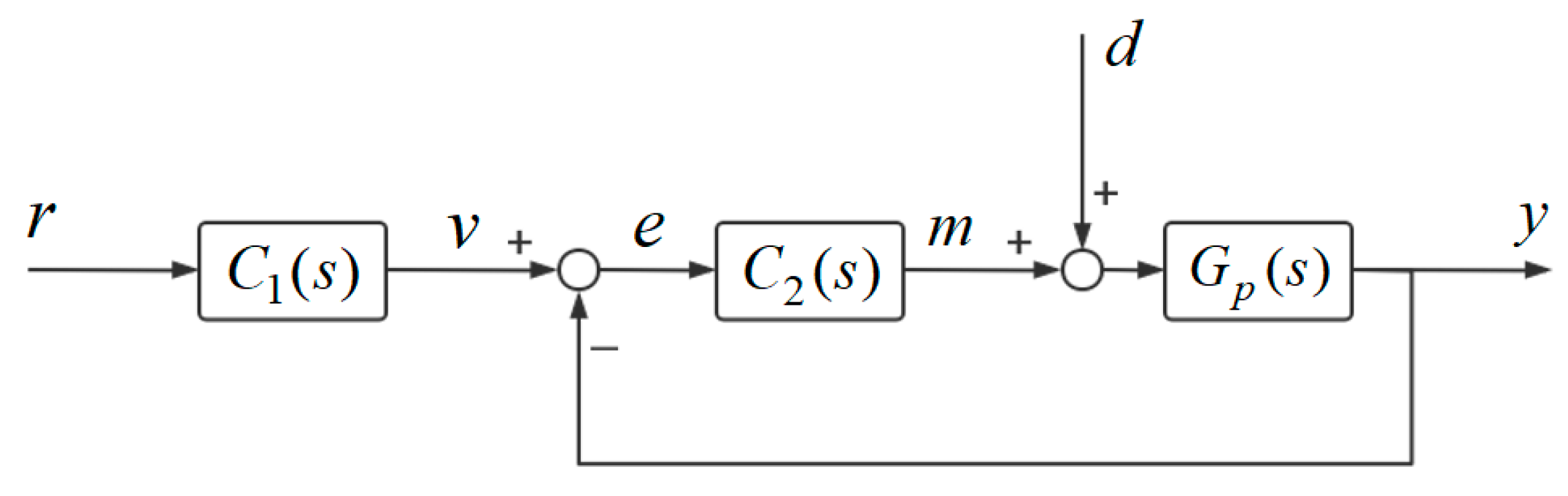
for the same input conditions. The system block diagram for the 1DOF PID control system F 2 and the 2DOF PID control system F 3 are given in Figure 6 and Figure 7.
Remark 3.
The transfer functions of the controllers shown in Figure 6 and Figure 7 are given as follows:
K ( s ) = k P ( 1 + k I s + k D s )
K f ( s ) = k P ( α + β k D s )
The 1DOF PID controller K ( s ) based on CRNs is established as
R ± k c a t R ± + E 1 ± , Y ± k c a t Y ± + E 1 , E 1 ± k deg
R + + R k a n n , Y + + Y k a n n , E 1 + + E 1 k a n n
E 1 ± l 1 E 1 ± + X 1 ± , X 1 ± k deg , X 1 + + X 1 k a n n
E 1 ± l 2 X 2 ± , X 2 + + X 2 k a n n
E 1 ± l 3 E 1 ± + X 3 ± , X 3 ± l 4 , X 3 + + X 3 k a n n
X 1 ± k c a t X 1 ± + V 1 ± , X 2 ± k deg X 2 ± + V 1 ± , V 1 ± k deg
X 3 ± k c a t X 3 ± + V 1 , V 1 + + V 1 k a n n
The feedforward controller K f ( s ) is built by CRNs in the following form
R ± k c a t R ± + E 2 ± , E 2 ± k deg
E 2 + + E 2 k a n n , R + + R k a n n
E 2 ± l 5 E 5 ± + X 4 ± , X 4 ± k deg , X 4 + + X 4 k a n n
E 2 ± l 6 E 2 ± + X 5 ± , X 5 ± l 7 , X 5 + + X 5 k a n n
X 5 ± k c a t X 5 ± + V 2 ± , X 4 ± k c a t X 4 ± + V 2
V 2 ± k deg , V 2 + + V 2 k a n n
The 2DOF PID controller shown in Figure 7 is modeled based on CRNs through Equations (45)–(57). The parameters of the control systems F 2 and F 3 have been tuned in [29,30]. The parameters of the controlled object G p ( s ) and the control system F 1 are given in Table 1. In Figure 8a, the rise time and settling time of the control system F 2 are shorter than the control systems F 1 and F 3 . However, the control system F 2 generates a large overshoot when the disturbance signal is d ( t ) = 0 ( t ) . The overshoot gets reduced by the control systems F 1 and F 3 , respectively. In Figure 8b, the rise time of the control system F 1 is longer than the control systems F 2 and F 3 .However, the performance of the control system F 1 is better than the control systems F 2 and F 3 for the overshoot and settling time. Table 2 and Table 3 are given to show the performance of the three control systems F i ( i = 1 , 2 , 3 ) . In addition, there are only two filtering parameters ( λ 1 and λ 2 ) to be adjusted in the 2DOF IMC-PID controller; the complexity of the controller parameter tuning is reduced.
Remark 4.
Figure 9 is given to show the output response curves of the 2DOF IMC-PID controller for different values of the two filtering parameters   λ 1 and   λ 2 . In the simulation shown in Figure 9, the step function   d ( t ) = 2 ( t ) is chosen as the disturbance input to the 2DOF IMC-PID control system   F 1 .
The parameter λ 1 is adjusted while keeping the parameter λ 2 constant in Figure 9a. As can be seen, the set-point following characteristic of the controller can be improved by reducing the filtering parameter λ 1 . Similarly, the parameter λ 2 is adjusted while keeping the parameter λ 1 constant. In Figure 9b, the disturbance rejection performance of the 2DOF IMC-PID controller gets improved by increasing the filtering parameter λ 2 . The performance of the controller for the different filtering parameters λ 1 and λ 2 are shown in Table 4 and Table 5.
As a conclusion, the set-point following performance of the controller can be improved by keeping the parameter λ 2 constant and reducing the parameter λ 1 . Similarly, the excellent disturbance suppression capability of the controller is attained by keeping the parameter λ 1 constant and reducing the parameter λ 2 .
Remark 5.
To better demonstrate the rejection performance of the 2DOF IMC-PID controller based on CRNs for different disturbance signals, the trigonometric signal   d ( t ) = ξ sin ω t is selected as the disturbance input. The suppression effect of the 2DOF IMC-PID controller based on the CRNs for the trigonometric signal d ( t ) = ξ sin ω t with different frequencies is simulated. The CRNs of the trigonometric signal d ( t ) = ξ sin ω t are as follows:
S ± ω S ± + D ± , D ± ω D ± + S
S ± k a n n , D ± k a n n
The initial species D ± is selected to join Equations (58) and (59), and S ± is the product. In Equation (58), the frequency of the trigonometric function d ( t ) = ξ sin ω t is determined by the reaction rate ω. The amplitude of the trigonometric function d ( t ) = ξ sin ω t is determined by the initial concentration of the reacting specie D ± , and the relationship between D ± and ξ is [ D + ] = ξ . When the trigonometric signal d ( t ) = sin ω t ( ξ = 1 ) is selected as the disturbance signal, the output response curves of the 2DOF IMC-PID control system F 1 are given in Figure 10.
In Figure 10, it can be seen that the trigonometric signal d ( t ) = sin ω t can be effectively suppressed by the 2DOF IMC-PID controller. However, the suppression effects are different for the trigonometric signals d ( t ) = sin ω t with different periods. The disturbance rejection performance of the controller is shown clearly in Figure 10b. It can be seen that the suppression effect of the 2DOF IMC-PID controller is more obvious when the period of d ( t ) = sin ω t is smaller. The initial concentrations and reaction rates of the trigonometric signals d ( t ) = sin ω t with different frequencies are defined in Table 6.

3.2. Simulation of DSD Reaction Networks

With the professional simulation software Visual DSD, the designs within the framework of CRNs can be automatically simulated to generate DSD reaction networks [41]. The 2DOF IMC-PID controller is constructed by three basic chemical reactions (i.e., catalysis, degradation, and annihilation), and now it is necessary to map the CRNs of the 2DOF IMC-PID controller into DSD reaction networks. With deterministic simulations, the output response profiles of the control systems F i ( i = 1 , 2 , 3 ) in DSD response networks are depicted in Figure 11.
The simulation results show that the 2DOF IMC-PID controller can achieve a steady-state following of the reference signal. The rise time of the control system F 2 is shorter than the control systems F 1 and F 3 , but the settling time of the control system F 1 is shorter than the control systems F 2 and F 3 . In addition, the overshoot generated by the 2DOF IMC-PID control system is smaller than the 1DOF PID control system and 2DOF PID control system. The performance of the three control systems F i ( i = 1 , 2 , 3 ) is shown in Table 7. The DSD reactions for constructing the 2DOF IMC-PID controller can be obtained in Visual DSD. (The relevant details are given in the Supplementary Materials.)
In this part, the effectiveness of the 2DOF IMC-PID control strategy in the DSD reaction networks is verified. The simulation results show that oscillations around the output signal become suppressed and overshoots become reduced with the 2DOF IMC-PID controller.

3.3. Building the Division Gate Control System to Restrain Leak Reactions

It has been verified that the design of the 2DOF IMC-PID controller is implementable within the framework of CRNs, and, next, the controller will be used to construct a division gate control system to suppress leak reactions. The division gate is established by combining the three operations of addition, subtraction, and multiplication, which achieves the ratio operation of the two biomolecular signals A and B [22].
The division gate in Figure 12 is built based on CRNs by Equations (60)–(63).
A ± μ 1 A ± + E ± , W ± μ 1 W ± + E
E ± μ 1 , E + + E k a n n
E ± i 1 E ± + C ± , C ± i 2 , C + + C k a n n
C ± + B ± μ 2 C ± + B ± + W ± , W ± μ 2 , W + + W k a n n
Equations (60) and (61) represent the error signal E and set μ 1 = 0.1   nM / s . Equation (62) produces the calculation result C , and the reaction rates i 1 = 0.01   nM / s and i 2 = 1 × 10 8   nM / s . Equation (63) offers the multiplication result of the output signal C with the input signal B and sets μ 2 = 1   nM / s . For example, the initial concentrations of the species are set to [ A + ] 0 = 6   nM and [ B + ] 0 = 3   nM . When the initial specie A is affected by the different extent of the leak reactions, it makes [ A + ] 0 < 6   nM and leads to the calculation of the division gate to a smaller C < A B . Similarly, when the initial specie B is affected by the different extent of the leak reactions, it makes [ B + ] 0 < 3   nM and leads to the calculation of the division gate to a bigger C > A B . The CRNs of the leak reactions are given as follows.
A γ
B γ
In Equations (64) and (65), the leak parameters γ and γ reflect the extent to which leak reactions occur. Figure 13 presents the effect of various levels of leak reactions on the computations.
As the leak reaction occurs more severely, the error of the calculation result of the divisor gate gets larger. The leak at the dividend leads to small calculations and the leak at the divisor leads to large results. The 2DOF IMC-PID division gate control system in Figure 14 is established to solve this problem; the calculation results are accurate even when leak responses occur in the division gate.
Different initial reaction concentrations and leak parameters are defined in Table 8. The first case is a leak in the initial specie A , and the other is a leak in the initial specie B . As Figure 15 shows, the calculation results of the 2DOF IMC-PID control system are acquired according to the parameters defined in Table 8.
Remark 6.
Another case is discussed for when the initial species   A and B leak simultaneously, and how the calculation result of the division gate changes. The calculation of the division gate is correct when the initial species A and B leak to the same level, but this is not the ideal result. Once the two species leak to different extents, the calculation result of the division gate will be wrong. However, the problem is solved by the 2DOF IMC-PID division gate control system. Figure 16 is given to show the calculations of the 2DOF IMC-PID division gate control system when the initial species A and B leak at the same time. As can be observed, the 2DOF IMC-PID division gate control system still obtains correct calculation results when there is a leak at both the divisor and dividend. The concentrations of the initial reaction species and the leak parameters are defined in Table 9.
The 2DOF IMC-PID division gate control system is designed to suppress leak reactions, and we discuss different cases of leak reactions of the initial species A and B in this part. The simulations show that the effectiveness of the 2DOF IMC-PID controller to restrain the leak reaction is demonstrated.

4. Conclusions

In this paper, the first-order time-delay system is selected as the control object, and a 2DOF IMC-PID controller is constructed by using CRNs as the programming language. The 2DOF IMC-PID controller is designed according to the mathematical model of the controlled subject by incorporating the IMC principle and the 2DOF control theory. With the 2DOF IMC-PID control tactics, the set-point tracking and disturbance suppression characteristics are decided by two independent controllers, respectively. The performance of the controller is obtained only by adjusting the two filtering parameters λ 1 and λ 2 , and the complexity of parameter tuning is greatly reduced compared with the 2DOF PID controller that requires five parameters to be adjusted. The 2DOF IMC-PID control strategy is verified to be effective in stabilizing biochemical reactions based on the DSD reaction network. The simulation results in Visual DSD show that the 2DOF IMC-PID controller has better set-point following and disturbance rejection capabilities. Uncertainty in the calculation results is caused by the leak reaction in the division gate. For this reason, a 2DOF IMC-PID division gate control system is established, and the leak reaction is considered as the external disturbance signal. Although there are leak reactions in the division gate, the calculations of the 2DOF IMC-PID division gate control system are still accurate, which proves that the 2DOF IMC-PID controller can effectively suppress the leak reactions. In future work, we will continue to explore the possibility of constructing molecular control circuits in biochemical reaction networks by combining some advanced optimization algorithms in the field of control engineering.

Supplementary Materials

The following supporting information can be downloaded at: https://github.com/ly810342287/Ly.

Author Contributions

Conceptualization, H.L. and Y.L.; data curation, Y.L.; formal analysis, Y.L.; investigation, Y.L.; methodology, Y.L.; project administration, H.L. and X.W.; resources, H.L.; software, Y.L.; supervision, H.L. and X.W.; validation, H.L., Y.L. and X.W.; visualization, Y.L.; writing—original draft, Y.L.; writing—review & editing, H.L. and X.W. All authors have read and agreed to the published version of the manuscript.

Funding

This work is supported by 111 Project (No. D23006), the National Natural Science Foundation of China (Nos. 62272079, 61972266), the Liaoning Revitalization Talents Program (No. XLYC2008017), the Natural Science Foundation of Liaoning Province (Nos. 2020-KF-14-05, 2021-MS-344, 2021-KF-11-03, 2022-KF-12-14), the Scientific Research Fund of Liaoning Provincial Education Department (No. LJKZZ20220147), the State Key Laboratory of Synthetical Automation for Process Industries, the State Key Laboratory of Light Alloy Casting Technology for High-end Equipment (No. LACT-006), the Postgraduate Education Reform Project of Liaoning province (No. LNYJG2022493), and the Dalian Outstanding Young Science and Technology Talent Support Program (No. 2022RJ08).

Institutional Review Board Statement

Not applicable.

Informed Consent Statement

Not applicable.

Data Availability Statement

The data supporting the results reported here are available from the corresponding author upon request.

Conflicts of Interest

The authors declare no conflict of interest.

Nomenclature

r Set-point input
d Disturbance input
y Output of the control system
τ Time-delay parameter
K Constant gain
s Poles
T Time constant
λ 1 , λ 2 Filtering parameters
K P Proportional gain
K I Integral gain
K D Derivative gain
α , β The 2DOF parameters
γ , γ The leak parameters

References

  1. Romeo, A.; Falconi, M.; Desideri, A.; Iacovelli, F. Reconstructing the Free Energy Profiles Describing the Switching Mechanism of a pH-Dependent DNA Nanodevice from ABMD Simulations. Appl. Sci. 2021, 11, 4052. [Google Scholar] [CrossRef]
  2. Bush, J.; Hu, C.-H.; Veneziano, R. Mechanical properties of DNA hydrogels: Towards highly programmable biomaterials. Appl. Sci. 2021, 11, 1885. [Google Scholar] [CrossRef]
  3. Stapleton, J.A.; Endo, K.; Fujita, Y.; Hayashi, K.; Takinoue, M.; Saito, H.; Inoue, T. Feedback control of protein expression in mammalian cells by tunable synthetic translational inhibition. ACS Synth. Biol. 2012, 1, 83–88. [Google Scholar] [CrossRef]
  4. Andries, O.; Kitada, T.; Bodner, K.; Sanders, N.N.; Weiss, R. Synthetic biology devices and circuits for RNA-based ‘smart vaccines’: A propositional review. Expert Rev. Vaccines 2015, 14, 313–331. [Google Scholar] [CrossRef]
  5. Chen, Y.-J.; Dalchau, N.; Srinivas, N.; Phillips, A.; Cardelli, L.; Soloveichik, D.; Seelig, G. Programmable chemical controllers made from DNA. Nat. Nanotechnol. 2013, 8, 755–762. [Google Scholar] [CrossRef] [Green Version]
  6. Fu, H.; Lv, H.; Zhang, Q. Using entropy-driven amplifier circuit response to build nonlinear model under the influence of Lévy jump. BMC Bioinform. 2021, 22, 437. [Google Scholar] [CrossRef]
  7. Clamons, S.; Qian, L.; Winfree, E. Programming and simulating chemical reaction networks on a surface. J. R. Soc. Interface 2020, 17, 20190790. [Google Scholar] [CrossRef] [PubMed]
  8. Shah, S.; Wee, J.; Song, T.; Ceze, L.; Strauss, K.; Chen, Y.-J.; Reif, J. Using strand displacing polymerase to program chemical reaction networks. J. Am. Chem. Soc. 2020, 142, 9587–9593. [Google Scholar] [CrossRef]
  9. Soloveichik, D.; Seelig, G.; Winfree, E. DNA as a universal substrate for chemical kinetics. Proc. Natl. Acad. Sci. USA 2010, 107, 5393–5398. [Google Scholar] [CrossRef] [Green Version]
  10. Shapiro, E.; Ran, T. Molecules reach consensus. Nat. Nanotechnol. 2013, 8, 703–705. [Google Scholar] [CrossRef]
  11. Mercurio, P.; Liu, D. Identifying transition states of chemical kinetic systems using network embedding techniques. Math. Biosci. Eng. 2021, 18, 868–888. [Google Scholar] [CrossRef] [PubMed]
  12. Zou, C.; Wei, X.; Zhang, Q.; Liu, C.; Liu, Y. Solution of equations based on analog DNA strand displacement circuits. IEEE Trans.Nanobiosci. 2019, 18, 191–204. [Google Scholar] [CrossRef] [PubMed]
  13. Beitz, A.M.; Oakes, C.G.; Galloway, K.E. Synthetic gene circuits as tools for drug discovery. Trends Biotechnol. 2021, 40, 210–225. [Google Scholar] [CrossRef] [PubMed]
  14. Shakiba, N.; Jones, R.D.; Weiss, R.; Del Vecchio, D. Context-aware synthetic biology by controller design: Engineering the mammalian cell. Cell Syst. 2021, 12, 561–592. [Google Scholar] [CrossRef]
  15. Frei, T.; Khammash, M. Adaptive circuits in synthetic biology. Curr. Opin. Struct. Biol. 2021, 28, 100399. [Google Scholar] [CrossRef]
  16. Tang, Z.; Yin, Z.; Wang, L.; Cui, J.; Yang, J.; Wang, R. Solving 0–1 integer programming problem based on DNA strand displacement reaction network. ACS Synth. Biol. 2021, 10, 2318–2330. [Google Scholar] [CrossRef]
  17. Foo, M.; Sawlekar, R.; Bates, D.G. Exploiting the dynamic properties of covalent modification cycle for the design of synthetic analog biomolecular circuitry. J. Med. Biol. Eng. 2016, 10, 15. [Google Scholar] [CrossRef] [Green Version]
  18. Zou, C.; Wei, X.; Zhang, Q. Visual synchronization of two 3-variable Lotka–Volterra oscillators based on DNA strand displacement. RSC Adv. 2018, 8, 20941–20951. [Google Scholar] [CrossRef] [Green Version]
  19. Zou, C.; Zhang, Q.; Wei, X. Compilation of a coupled hyper-chaotic Lorenz system based on DNA strand displacement reaction network. IEEE Trans. Nanobiosci. 2020, 20, 92–104. [Google Scholar] [CrossRef]
  20. Wang, Y.; Li, Z.; Sun, J. Three-variable chaotic oscillatory system based on DNA strand displacement and its coupling combination synchronization. IEEE Trans. Nanobiosci. 2020, 19, 434–445. [Google Scholar] [CrossRef]
  21. Xing, C.; Zheng, X.; Zhang, Q. Constructing DNA logic circuits based on the toehold preemption mechanism. RSC Adv. 2021, 12, 338–345. [Google Scholar] [CrossRef] [PubMed]
  22. Foo, M.; Sawlekar, R.; Kim, J.; Bates, D.G.; Stan, G.-B.; Kulkarni, V. Biomolecular implementation of nonlinear system theoretic operators. In Proceedings of the 2016 European Control Conference (ECC), Aalborg, Denmark, 29 June–1 July 2016; pp. 1824–1831. [Google Scholar]
  23. Song, T.; Garg, S.; Mokhtar, R.; Bui, H.; Reif, J. Analog computation by DNA strand displacement circuits. ACS Synth. Biol. 2016, 5, 898–912. [Google Scholar] [CrossRef]
  24. Oishi, K.; Klavins, E. Biomolecular implementation of linear I/O systems. IET Syst. Biol. 2011, 5, 252–260. [Google Scholar] [CrossRef] [PubMed] [Green Version]
  25. Yordanov, B.; Kim, J.; Petersen, R.L.; Shudy, A.; Kulkarni, V.V.; Phillips, A. Computational design of nucleic acid feedback control circuits. ACS Synth. Biol. 2014, 3, 600–616. [Google Scholar] [CrossRef]
  26. Sawlekar, R.; Montefusco, F.; Kulkarni, V.V.; Bates, D.G. Implementing nonlinear feedback controllers using DNA strand displacement reactions. IEEE Trans Nanobiosci. 2016, 15, 443–454. [Google Scholar] [CrossRef] [PubMed] [Green Version]
  27. Foo, M.; Sawlekar, R.; Kulkarni, V.V.; Bates, D.G. Biologically inspired design of feedback control systems implemented using DNA strand displacement reactions. In Proceedings of the 2016 38th Annual International Conference of the IEEE Engineering issn Medicine and Biology Society (EMBC), Orlando, FL, USA, 16–20 August 2016; pp. 1455–1458. [Google Scholar]
  28. Foo, M.; Kim, J.; Sawlekar, R.; Bates, D.G. Design of an embedded inverse-feedforward biomolecular tracking controller for enzymatic reaction processes. Comput. Chem. Eng. 2017, 99, 145–157. [Google Scholar] [CrossRef] [PubMed]
  29. Paulino, N.M.; Foo, M.; Kim, J.; Bates, D.G. PID and state feedback controllers using DNA strand displacement reactions. IEEE Contr. Syst. Lett. 2019, 3, 805–810. [Google Scholar] [CrossRef]
  30. Yuan, Y.; Lv, H.; Zhang, Q. DNA strand displacement reactions to accomplish a two-degree-of-freedom PID controller and its application in subtraction gate. IEEE Trans. Nanobiosci. 2021, 20, 554–564. [Google Scholar] [CrossRef]
  31. Wang, Y.; Ji, H.; Wang, Y.; Sun, J. Stability based on PI control of three-dimensional chaotic oscillatory system via DNA chemical reaction networks. IEEE Trans. Nanobiosci. 2021, 20, 311–322. [Google Scholar] [CrossRef]
  32. Yuan, Y.; Lv, H.; Zhang, Q. Molecular device design based on chemical reaction networks: State feedback controller, static pre-filter, addition gate control system and full-dimensional state observer. J. Math. Chem. 2022, 60, 915–935. [Google Scholar] [CrossRef]
  33. Araki, M.; Taguchi, H. Two-degree-of-freedom PID controllers. Int. J.Control Autom. Syst. 2003, 1, 401–411. [Google Scholar]
  34. Wu, S.; Li, Z.; Zhang, R. An improved 2-degree-of-freedom internal model proportional–integral–derivative controller design for stable time-delay processes. Meas. Control 2020, 53, 841–849. [Google Scholar] [CrossRef] [Green Version]
  35. Singh, J.; Chattterjee, K.; Vishwakarma, C. Two degree of freedom internal model control-PID design for LFC of power systems via logarithmic approximations. ISA Trans. 2018, 72, 185–196. [Google Scholar] [CrossRef]
  36. Sonker, B.; Kumar, D.; Samuel, P. Design of two degree of freedom-internal model control configuration for load frequency control using model approximation. Int. J. Simul. Model. 2019, 39, 27–37. [Google Scholar] [CrossRef]
  37. Chekari, T.; Mansouri, R.; Bettayeb, M. Real-time application of IMC-PID-FO multi-loop controllers on the coupled tanks process. Proc. Inst. Mech. Eng. Part I J. Syst. Control Eng. 2021, 235, 1542–1552. [Google Scholar] [CrossRef]
  38. Liu, D.; Wang, G.; Liu, J.; Fan, Y.; Mu, D. An Improved Vector Control Strategy for Switched Reluctance Motor Drive Based on the Two-Degree-of-Freedom Internal Model Control. Appl. Sci. 2022, 12, 5407. [Google Scholar] [CrossRef]
  39. Bingi, K.; Ibrahim, R.; Karsiti, M.N.; Hassan, S.M.; Harindran, V.R. Fractional-Order Systems and PID Controllers; Springer: Berlin/Heidelberg, Germany, 2020; Volume 264. [Google Scholar]
  40. Roy, R.; Islam, M.; Rashid, M.; Mounis, S.; Ahsan, M.M.; Ahad, M.T.; Siddique, Z.; Kouzani, A.Z.; Mahmud, M.P.J.A.S. Investigation of 2dof pid controller for physio-therapeutic application for elbow rehabilitation. Appl. Sci. 2021, 11, 8617. [Google Scholar] [CrossRef]
  41. Carlo Spaccasassi, N.D.; Lakin, M.; Petersen, R.; Phillips, A. Visual DSD User Manual; Microsoft Research: Cambridge, UK, 2019. [Google Scholar]
Figure 1. The 2DOF control structure with IMC controller.
Applsci 13 03402 g001
Figure 2. The 2DOF control structure of set-point filter type.
Applsci 13 03402 g002
Figure 3. Set-point filter C 1 ( s ) .
Applsci 13 03402 g003
Figure 4. PID controller C 2 ( s ) .
Applsci 13 03402 g004
Figure 5. 2DOF IMC-PID control system F 1 .
Applsci 13 03402 g005
Figure 6. 1DOF PID control system F 2 .
Applsci 13 03402 g006
Figure 7. 2DOF PID control system F 3 .
Applsci 13 03402 g007
Figure 8. Output response curves of three control systems F i ( i = 1 , 2 , 3 ) : (a) when there is no disturbance input of systems; (b) when the disturbance signal of systems is d ( t ) = 1 ( t ) .
Applsci 13 03402 g008
Figure 9. Output response curves of the 2DOF IMC-PID controller: (a) variation in controller set-point tracking performance; (b) variation in controller disturbance rejection performance.
Applsci 13 03402 g009
Figure 10. (a) Output response curves of the 2DOF IMC-PID control system F 1 when the disturbance inputs are trigonometric functions d ( t ) = sin ω t with different frequencies. (b) The disturbance suppression performance of 2DOF IMC-PID controller.
Applsci 13 03402 g010
Figure 11. Output responses of three control systems F i ( i = 1 , 2 , 3 ) .
Applsci 13 03402 g011
Figure 12. The structure of the division gate.
Applsci 13 03402 g012
Figure 13. Leak reactions lead to errors in calculation results: (a) leak in the initial specie A ; (b) leak in the initial specie B .
Applsci 13 03402 g013
Figure 14. The 2DOF IMC-PID division gate control system.
Applsci 13 03402 g014
Figure 15. Calculation results of 2DOF IMC-PID division gate control system: (a) leak reaction at the divisor; (b) leak reaction at the dividend.
Applsci 13 03402 g015
Figure 16. Calculations of the division gate control system when the initial species A and B leak simultaneously.
Applsci 13 03402 g016
Table 1. Parameters of controlled object G p ( s ) and control systems F i ( i = 1 , 2 , 3 ) .
Controlled   Object   G p Control   System   F 1 Control   System   F 2 , F 3
τ = 10 5   s K = 1 T = 2 × 10 5   s k c a t = 1 nM / s k deg = 1 nM / s k a n n = 1 nM / s λ 1 = 1.75 × 10 5 λ 2 = 1 × 10 5 k c a t = 1 nM / s k deg = 1 nM / s k a n n = 1 nM / s k P = 2 k I = 9.5 × 10 6   s 1 k D = 5 × 10 5   s α = 0.05 β = 0.04 k c a t = 1 nM / s k deg = 1 nM / s k a n n = 1 nM / s
Table 2. Performance of three control systems without disturbance input.
Control System r ( t ) = 1 ( t ) , d ( t ) = 0 ( t )
Rise TimeSettling TimeOvershoot
2DOF IMC-PID Control System F 1 587,737 s892,306 s0.016%
1DOF PID Control System F 2 [29,30]150,079 s355,008 s10.88%
2DOF PID Control System F 3 [30]410,777 s538,101 s0.48%
Table 3. Performance of three control systems when the disturbance signal is d ( t ) = 1 ( t ) .
Control System r ( t ) = 1 ( t ) , d ( t ) = 1 ( t )
Rise TimeSettling TimeOvershoot
2DOF IMC-PID Control System F 1 573,587 s900,343 s0.024%
1DOF PID Control System F 2 [29,30]238,511 s979,059 s12.10%
2DOF PID Control System F 3 [30]427,343 s990,834 s2.48%
Table 4. Effect of filtering parameter λ 1 on controller set-point tracking performance.
Filter   Parameter   λ 1   and   λ 2 Rise TimeSettling TimeOvershoot
A : λ 1 = 1.5 × 10 5 , λ 2 = 10 5 526,379 s665,496 s0.047%
B : λ 1 = 2 × 10 5 , λ 2 = 10 5 634,209 s778,493 s0.037%
C : λ 1 = 3 × 10 5 , λ 2 = 10 5 850,657 s1,049,520 s0.056%
Table 5. Effect of filtering parameter λ 2 on controller disturbance rejection performance.
Filter   Parameter   λ 1   and   λ 2 Rise TimeSettling TimeOvershoot
D : λ 1 = 2.8 × 10 5 , λ 2 = 0.75 × 10 5 252,556 s276,659 s2.21%
E : λ 1 = 2.8 × 10 5 , λ 2 = 1.5 × 10 5 250,733 s775,082 s9.08%
F : λ 1 = 2.8 × 10 5 , λ 2 = 2 × 10 5 248,043 s1,014,084 s15.85%
Table 6. The initial species concentrations and reaction rate ω .
Initial   Species   Concentrations   D + Reaction Rate ω
D + = 1   nM ω = 0.0002   nM / s
D + = 1   nM ω = 0.0001   nM / s
D + = 1   nM ω = 0.00005   nM / s
Table 7. Performance of three control systems F i ( i = 1 , 2 , 3 ) in DSD reaction networks.
Control SystemRise TimeSettling TimeOvershoot
2DOF IMC-PID Control System F 1 32,188 s, 112,726 s, 192,486 s40,165 s, 123,250 s, 202,671 s0.51%, 1.15%, 0.48%
1DOF PID Control System F 2 [29,30]5601 s, 85,619 s, 165,459 s47,740 s, 137,540 s, 212,244 s26.8%, 51.7%, 27.9%
2DOF PID Control System F 3 [30]19,153 s, 99,125 s, 180,331 s40,211 s, 125,989 s, 205,643 s4.59%, 10.2%, 4.72%
Table 8. Two cases of initial species concentrations and leak parameters γ and γ .
Leak in Initial Species A Leak in Initial Species B
[ A ] 0 = 21   nM , [ B ] 0 = 7   nM , γ = 0.1 [ A ] 0 = 24   nM , [ B ] 0 = 8   nM , γ = 0.1
[ A ] 0 = 22   nM , [ B ] 0 = 11   nM , γ = 0.2 [ A ] 0 = 18   nM , [ B ] 0 = 9   nM , γ = 0.2
[ A ] 0 = 35   nM , [ B ] 0 = 7   nM , γ = 0.3 [ A ] 0 = 36   nM , [ B ] 0 = 9   nM , γ = 0.3
Table 9. The initial species concentrations and leak parameters γ and γ .
The Initial Species ConcentrationsLeak Parameters
[ A ] 0 = 16   nM , [ B ] 0 = 8   nM γ = 0.2 , γ = 0.1
[ A ] 0 = 36   nM , [ B ] 0 = 12   nM γ = γ = 0.1
[ A ] 0 = 15   nM , [ B ] 0 = 10   nM γ = 0.1 , γ = 0.2
Disclaimer/Publisher’s Note: The statements, opinions and data contained in all publications are solely those of the individual author(s) and contributor(s) and not of MDPI and/or the editor(s). MDPI and/or the editor(s) disclaim responsibility for any injury to people or property resulting from any ideas, methods, instructions or products referred to in the content.

