2.2. Optical Components for the NHD System
We discuss optical components for the near-eye holographic display system, for which a schematic architecture is illustrated in
Figure 2a. Collimated light from the green laser with 532 nm wavelength (CNI optoelectronics, MGL-S-532) is generated by using a first positive lens located just after the fiber-coupled laser source as a coherent illumination. To upload holographic 3D content, a flat LCoS-SLM panel that modulates an 8-bit grey-scaled amplitude is modified as a direct-viewing SLM type. First, the polarization direction of the illuminating light is parallel to that of a transparent, film-typed PBS (polarizing beam splitter), which is positioned at the input surface of the LCoS. Second, near the surface of the SLM, a second convex lens called a field lens is placed against the SLM to converge the output light toward the eye box of the observer. The active area of the LCoS-SLM is 12.1 mm (V) × 6.80 mm (H). It supports a pixel arrangement of a nearly rectangular-shaped matrix geometry. This pixel geometry generates an extension of the zeroth diffraction order in the Fourier plane, i.e., a virtual observation window (VW), which corresponds to the area of the eye box of the observer [
10,
16,
17]. The size of VW along the
i-axis (
i =
x,
y) is approximately given by
, where
is the pixel pitch of the SLM along the
i-axis,
f the focal length of the field lens, which is also related to the viewing distance of the observer from the SLM, and
the wavelength of illumination light. The size of the wavelength-dependent VW is designed to become larger than the pupil size of the human eye [
18,
19,
20]. Thus,
f = 500 mm is chosen for
= 532 nm to obtain
= 42.2 mm (along the horizontal direction) and
= 42.2 mm (along the vertical direction). The optical wave field emerging from a 3D object or scene can be directly observed within the region of VW with the help of both the transparent PBS film and the field lens, thus leading to holographic augmented reality (AR), enabling the viewer to experience genuine depth cues and an accommodation effect. Further, optical observation and an experimental evaluation of the optically reconstructed holographic 3D (H3D) images are performed near the area of VW at the eye position (see
Figure 2a) and demonstrated by a camera-captured, holographic 3D (H3D) scene reconstructed from CGHs. As shown in
Figure 2, the proposed near-eye holographic 3D display (NEHD) system consists of two split main components so that binocular observation can be achieved; after a collimated beam is split into two parts, its left-side part is designed to focus an incident beam towards the left-eye and the other part towards the right-eye.
Passing through each SLM, the light wave fields then are guided into two independent focal points corresponding to the two eyes’ observational positions. The separation between these two positions is equal to 65 mm in the eye plane of the observer, where the distance corresponds to the average binocular distance of a human [
21,
22] and is indicated as a binocular distance (BD) in
Figure 2a.
2.3. Acquisition of 360° Multi-Viewed Holographic Content from a 3D Model
A depth map image, representing information on the distance between the surface of an object and the observation point in the unit of the greyscale, is useful to make 3D content modeling for hologram synthesis. It is necessary that a set of RGB color and depth map images per view be extracted from a 3D object, so that we may calculate CGH by using the algorithm of FFT-based cascaded Fresnel transform (see Equation (1)). In this study, instead of choosing specific camera sensors to capture depth information, such as Kinect or Real sensors, we use MAYA 2018
TM software [
23] to design a 3D scene to give depth cues for holographic content. The software has the added advantage of rendering to capture the 3D object with a full range of 360 degrees. To experimentally observe the accommodation effect from holographic content, we design a 3D scene that consists of two Rubik’s cubes in green, each positioned at sufficiently. different distance to generate dynamic occlusion and to differentiate between focal depths.
Figure 3 shows the layout where two objects and a virtual camera are placed in the same plane, representing (a) a perspective view and (b) an in-plane view observed near the position of the camera eye. The camera can be programmed to orbit only along a virtual circular tract with the desired speed. While taking a turn on the circular orbit, the camera keeps shooting the 3D scene to obtain a total of 1024 frames, each shot with a constant increment of 0.352°, capturing a set of RGB images and depth maps simultaneously. Then both the RGB color and depth map images are stored in an 8-bit greyscale with BMP format. The distance from the center-of-mass of two objects to the camera’s orbit is measured and varied through a menu bar called a Distance Tool in MAYA
TM, and the depth value from the camera eye can then be manually adjusted by the user to determine the optimal depth range.
After the process of rendering in MAYATM is completed, a set of RGB and depth map images per frame, each holding FHD (1920 × 1080) resolution, is extracted. Thus, after a circular loop of the camera, the database where images are saved is composed of 1024 views. Through this process, we obtain RGB images and depth images of the target scene for generating 360° moving, holographic content.
2.4. Synthesis of CGH
The CGH synthesis for near-eye holographic content is explained on the basis of the wave optics and Fresnel’s holographic model in the system schematically illustrated in
Figure 4 [
10,
11,
12]. We assume that the distance (
) between the holographic display and the eye lens is equal to the focal length (
) of the field lens. When the size of eyeball and the focal length of eye lens are given as
and
, we also assume that the hologram plane (
,
) near the field lens and the retinal plane (
,
) of the user are located in parallel with the eye lens plane (
u,). The optical field at the display panel with size of
and that of retinal domain of the observer are denoted as
and
, respectively. These fields are related to the following equation, called a cascaded Fresnel transform [
24,
25]:
where
, and
While an image formed at the retinal plane is analyzed using the direct cascaded Fresnel transform, as given in Equation (1), making the desired image formation the optical field input at the display plane (
,
) is calculated using an inverse cascaded Fresnel transform. On the basis of Equation (1), the desired hologram field
in the display domain is synthesized after a process of superposition of a reference wave field with the initially calculated optical field
. It is assumed that the reference wave field is the complex amplitude of the illumination wave from the backlight unit that is collimated, normally incident with a constant amplitude. In addition to the reference wave, we superimpose an off-axis carrier wave
on the calculated optical field
so that the desired signal function may shift from the noise terms, such as the DC term, and the twin-conjugate image. Through direct observation tests of each eye from H3D reconstructions, we experimentally derived the optimized conditions for the carrier wave format of
, with
a = 0.048 and
b = 0.128, in applying the current-considered optical geometry (see
Figure 4). Therefore, we could finally synthesize the signal function for the digital hologram
; the signal function contains complex numbers in general, and can be expressed by
, where
is the amplitude of
and
is its phase. Here, the CGH’s original function must be converted into an appropriate representation, that is, amplitude-modulating hologram data suitable for the study, because we use the amplitude-modulating SLM in our system.
2.5. Encoding Methods for the Amplitude-Modulating Device
In this section, we first explore the established approaches to convert the complex-valued hologram to express the amplitude-modulating SLM (AM-SLM). We then propose our novel encoding scheme, i.e., the modified amplitude-only encoding (MAO) approach.
Among methods to circumvent the non-availability of commercial complex-modulating SLMs, a conventional amplitude-only encoding (CAO) [
16] has been used. The CAO approach is to extract only the real part of a complex-valued optical field at the pixel coordinates of the hologram plane, and subsequently to bias the real-valued space into nonnegative, real-valued space by level shifting, which can be written as
where
is the real part of the original complex field, and
is an offset to make
non-negative and is equal to the absolute value of a minimum of
for the CAO, i.e.,
.
On the other hand, as an alternative representation format of computer-generated holograms (CGHs) available for the AM-SLM, there are two kinds of effective solutions from an analytic perspective: The first analytic representation scheme is Lee’s method, which decomposes a complex-valued field into four real and non-negative components [
13]. The decomposition by Lee’s method is expressed as
where at least two among four coefficients
are equal to zero. The relative phase values for Lee’s method are physically implemented by lateral displacement within a single macro-pixel that consists of four sub-pixels. Alternatively, Burckhardt’s method, which is a simplified version of Lee’s method, uses the feature that any complex-valued function can be analytically decomposed into three real and nonnegative components. The decomposition by Burckhardt’s method can be expressed by
where at least one among the three coefficients
is equal to zero [
14,
15]. The relative phase values for Burckhardt’s method are realized by lateral displacement within one macro-pixel that comprises three sub-pixels.
Finally, the equational representation of the modified amplitude-only encoding (MAO) method we propose is described in the following formula, provided that the minimum of
is negative:
where
is an intermediate function and is defined by
This formula of the MAO scheme has two key features: (i) For the pixel of
, the intermediate function
is not changed from
and retains the original form of
. The result of MAO encoding is thus equivalent to that of conventional amplitude-only encoding, that is,
. (ii) For the pixel of
, a scale-down transform process is first performed before
is divided by the minimal value of
. Its effect reduced with a fixed rate is determined by a parametric factor
, where
is assumed. When we prepare the intermediate function
, we finally obtain
just after subtracting
by its minimum [see Equation (5)]. Using the above-explained approaches, we establish the framework that consist of four different kinds of amplitude holograms, each of which is converted from the original, complex-valued hologram calculated by the FFT algorithm and is prepared for experimental comparison.
Figure 5 shows the results of each encoding using the same original CGH function generated from a set of RGB and depth map images as shown in
Figure 3c,d, with the MAO encoding processed under the condition of
.
For the observer to experience an enhanced three-dimensional effect, two different viewpoints about a given 3D scene are required. Hence, for the dual-view holographic display, we made a set of CGH frames by selectively sorting two images per CGH frame among 1024 prepared images to provide 360° full views of the scene. We now explain that the viewing-point difference per CGH frame has a gap of 8 numbers from a series of 1024 views with a time-sequential difference. For example, the first view image for the left eye and the ninth view image for the right eye can be chosen as the first CGH content for a single frame. The reason is as follows: when the radius of the circular sector, i.e., the distance between the eyes’ plane and the object’s plane, is 1.4 m, the arc, i.e., the average distance (BD) between the eyes, is 65 mm [
21,
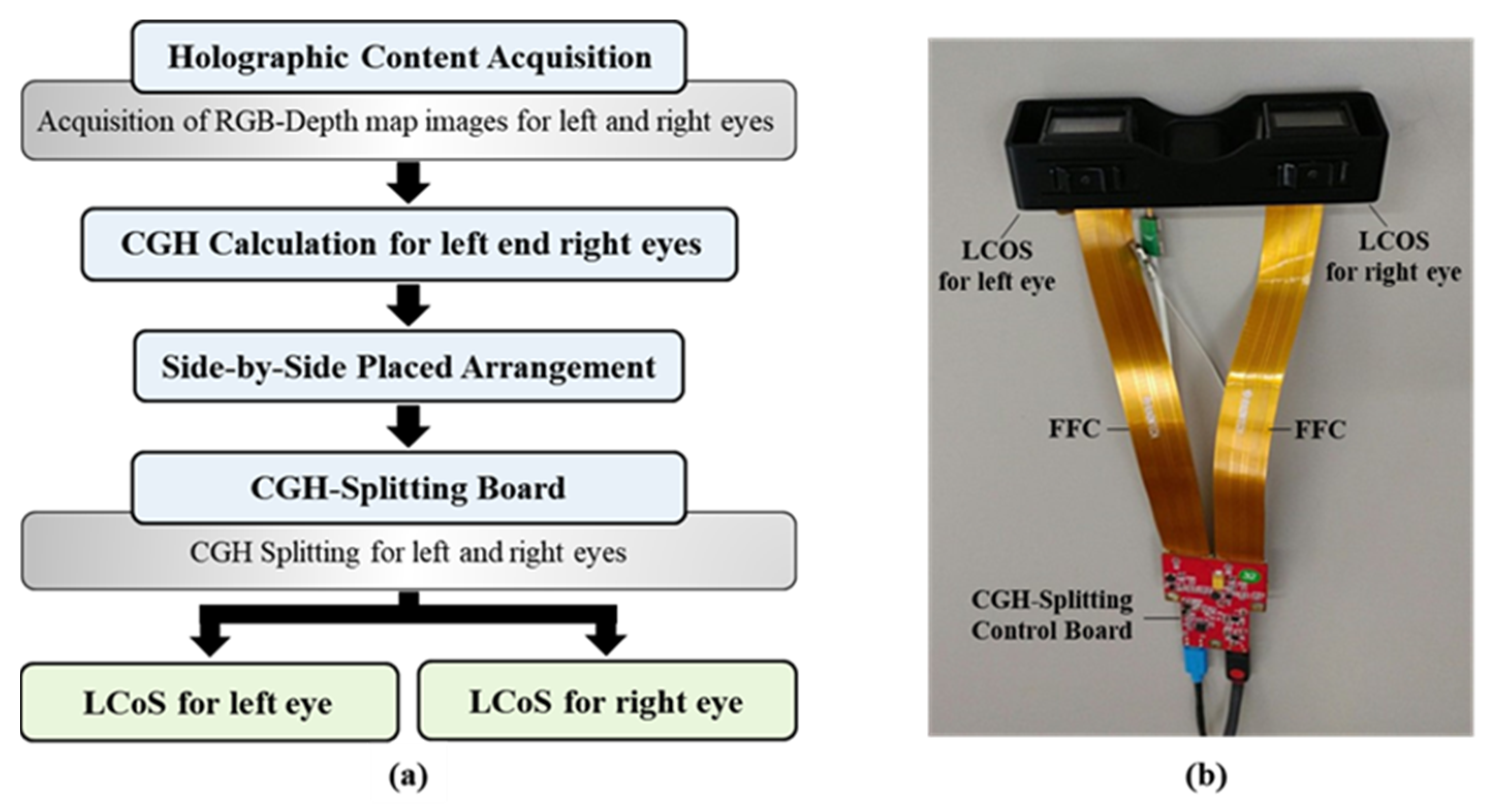
22], and thus their central angle should be 2.66°. Because the central angle increment per image is 0.352°, the view-number difference between the view of left eye and the view of right eye is equal to 8. A brief recapitulation of preparing CGH content fit with the NEHD system is as follows: (i) We obtained two complex hologram matrices through the FFT algorithm from the first set that consists of one RGB-depth image for the left eye and the other for the right eye (see
Figure 6). (ii) Then we computed the four types of CGH content by using CAO, MAO, Lee’s, and Burckhardt’s encoding methods. For each encoding, a pair of calculated CGHs are combined in a side-by-side arrangement and stored as an image file with a resolution of 3840 × 1080.
Figure 6 shows an exemplary process in the case of MAO encoding to prepare the first CGH frame for our dual-view holographic display. Here, we chose two sets of RGB-depth images with different viewpoints; one is for the first viewpoint and the other is for the ninth viewpoint. (iii) We repeated the above process about the 360° full range to create the final holographic content fit for the binocular geometry. (iv) Finally, we converted the time-sequential 360° views’ CGH set into an uncompressed video file, which can show a holographic 3D movie with a speed of 30 frames per second (fps) [see the Supplementary video (a)~(d)].


