Article

Optimal Interplanetary Transfer of Solar Wind Ion Focusing Thruster-Based Spacecraft

Department of Civil and Industrial Engineering, University of Pisa, 56122 Pisa, Italy
*
Author to whom correspondence should be addressed.
Appl. Sci. 2023, 13(6), 3820; https://doi.org/10.3390/app13063820
Submission received: 29 December 2022 / Revised: 10 March 2023 / Accepted: 15 March 2023 / Published: 16 March 2023
(This article belongs to the Special Issue Recent Advances in Space Propulsion Technology)

Abstract

:
The Solar Wind Ion Focusing Thruster (SWIFT) is a highly-innovative propellantless propulsion concept, recently proposed by Gemmer and Mazzoleni. In its nominal configuration, a SWIFT consists of a conically-shaped mesh of positively-charged conducting tethers, with its vertex linked to the spacecraft and its axis oriented towards the Sun. The SWIFT collects and filters the solar wind plasma and suitably directs the positive ions, which are then accelerated by an ion thruster. Such a device is theoretically able to generate a deep-space propulsive acceleration that comes, in part, from the solar wind dynamic pressure impinging on the conical grid and, in part, from the positive ion beam. In particular, the orientation of the ion beam may be chosen in such a way as to set the resultant propulsive acceleration and steer the spacecraft. The aim of this paper is to analyze the performance of a SWIFT-propelled spacecraft in an orbit-to-orbit two-dimensional interplanetary transfer. To that end, some mission scenarios are studied, in an optimal framework, by minimizing the total flight time necessary for the spacecraft to complete the transfer as a function of the propulsion system performance parameters. Numerical simulations are used to compare the optimal flight times calculated in simplified Earth–Venus and Earth–Mars transfers with those obtained by considering other propellantless propulsion systems.

1. Introduction

Propellantless systems are the frontier of current and near-term technology for space propulsion and are likely to become the only viable way to realize new advanced mission concepts, such as reaching high-energy orbits of comets [1,2] or Solar System small bodies [3,4,5], rectilinear trajectories [6,7], displaced orbits [8,9,10,11], or the creation and maintenance of artificial Lagrangian points [12,13,14] and hovering conditions over asteroids [15]. Solar sails and electric solar wind sails (E-sails) are currently the most promising types of propellantless systems. They are both able to gain energy from the Sun, although with different physical mechanisms. On one side, solar sails are propelled by the momentum transfer of solar photons impinging on a large, lightweight, and reflecting membrane [16,17,18,19,20]. E-sails, instead, produce a propulsive thrust by extracting momentum from the solar wind ions, which are shielded by an electric field generated around a large grid of conducting tethers [21,22]. Despite their different working principles, the common feature of solar sails and E-sails is that both require large surfaces to produce thrust and that those surfaces must be suitably oriented with respect to the Sun–spacecraft (that is, radial) direction to generate a thrust component capable of modifying the spacecraft orbital momentum [16,23,24]. Their other common feature is that the maximum thrust magnitude, for a given distance from the Sun, is obtained when the reference plane (either the reflecting membrane or the nominal plane containing the conducting tethers) is placed normal to the radial direction [25].
The need to reorient the reference plane for guidance and navigation purposes gives rise to a double issue. In the first place, the rotations of the plane may represent a complex task to carry out, especially when large reorientation angles are involved. However, even more important is the propulsive effect caused by the rotation, since, as the reference plane strays from a Sun-facing orientation, the solar wind ions and photons “see” a smaller surface to hit, with a consequent reduction of thrust magnitude. Alternative configurations have been proposed to mitigate these drawbacks. For example, in the case of photonic propulsion systems, the functions of collecting and directing the solar radiation may be separated by means of an arrangement that is called Solar Photon Thrustor (SPT), according to its original definition by Robert Forward [26]. In that system, the solar rays impinging on a collector (a large curved reflecting surface) are first directed on a small flat mirror, the reflector, which redirects them on a second steerable mirror, the director, used to suitably orient the force acting on the SPT. Since the collector is always oriented orthogonal to the Sun-pointing direction, it always produces the maximum allowable thrust magnitude for a given collector reflecting surface. Due to its special arrangement, a typical SPT configuration is, in principle, superior to a conventional solar sail, as it may be concluded from simulations of Earth escape trajectories [27] or interplanetary trajectories [28,29]. Updated results, made on realistic SPT configurations, have however called into question the actual effectiveness of this advanced propulsion concept [30].
Returning to systems that extract momentum from the solar wind ions, the Solar Wind Ion Focusing Thruster (SWIFT) is a new propellantless device, which may be thought of as an evolution of the E-sail concept [31,32,33]. It essentially consists of a grid of conducting tethers, electrostatically charged at a positive electric potential, arranged in a conically-shaped mesh with a circular base that has a radius of some kilometers and is supported by a few auxiliary booms with stiffening purposes. The solar wind ions are filtered by the charged SWIFT cone and the collected positive ions are accelerated by an ion thruster and then ejected in a beam that can be suitably oriented to provide the desired thrust component. The propulsion system also includes a cathode (or other suitable electron source) to prevent the thruster from accumulating a net charge. Since the SWIFT cone axis always points to the Sun, the functions of collecting and directing the solar wind ions are separated, and for this reason the SWIFT concept has interesting similarities with the Forward’s SPT configuration. So far, however, a reasonable estimate of the SWIFT capabilities is still lacking and is confined to the preliminary analysis in Ref. [34], where Gemmer et al. have reported some parametric studies about flyby missions to Venus and Mars. The aim of this paper is to fill that gap and quantify the SWIFT’s performance in a systematic way, by translating the analysis into the solution of a minimum-time interplanetary transfer problem. In this case, the optimal (i.e., minimum-time) trajectories are obtained with an indirect approach by enforcing the necessary conditions for optimality according to the Pontryagin’s maximum principle [35]. In particular, the Hamiltonian associated to the problem is maximized at any time by maximizing the projection of the propulsive acceleration vector along the direction of the Lawden’s primer vector [36,37].
This paper is organized as follows. The next section describes the spacecraft dynamics in a heliocentric mission scenario and provides an extension of the thrust model recently discussed in Ref. [34]. The analytic expression of the spacecraft propulsive acceleration vector is then used in Section 3 to optimize the spacecraft transfer trajectory in a circle-to-circle coplanar orbit transfer, while Section 4 discusses the optimal results obtained by numerically simulating two potential (and simplified) interplanetary missions towards Mars and Venus. Finally, the last section summarizes and highlights the main outcomes of this work.

2. Mathematical Model

The performance of a SWIFT-based spacecraft is here investigated assuming that the mission consists of a heliocentric transfer trajectory between two circular and coplanar orbits. Such a two-dimensional spacecraft motion may be conveniently described with the aid of a heliocentric polar reference frame T ( O ; r , θ ) , whose origin O coincides with the Sun’s center of mass; r is the Sun–spacecraft distance, and θ is the spacecraft polar angle measured counterclockwise from a fixed direction, which coincides with the Sun–spacecraft line at the initial time t = t 0 0 ; see Figure 1.
The fundamental unit vectors of T are denoted by { i ^ r , i ^ θ } , where i ^ r is the outward radial unit vector, and i ^ θ is the circumferential unit vector, so that the spacecraft position ( r ) and velocity ( v ) vectors can be written in T as
r = r i ^ r , v = v r i ^ r + v θ i ^ θ ,
where v r (or v θ ) is the radial (or circumferential) component of v . In the polar reference frame, the SWIFT-induced propulsive acceleration is written as a function of the radial ( a r ) and circumferential ( a θ ) components as
a = a r i ^ r + a θ i ^ θ ,
so that the spacecraft equations of motion are
r ˙ = v r
θ ˙ = v θ r
v ˙ r = v θ 2 r μ r 2 + a r
v ˙ θ = v r v θ r + a θ ,
where the dot symbol denotes a derivative with respect to time t, and μ is the Sun’s gravitational parameter. The resultant (spacecraft) heliocentric trajectory requires a suitable model describing the SWIFT-induced propulsive acceleration components as a function of the solar wind properties and of the propulsion system design parameters. Such a model is illustrated in the next section.

Thrust Vector Description

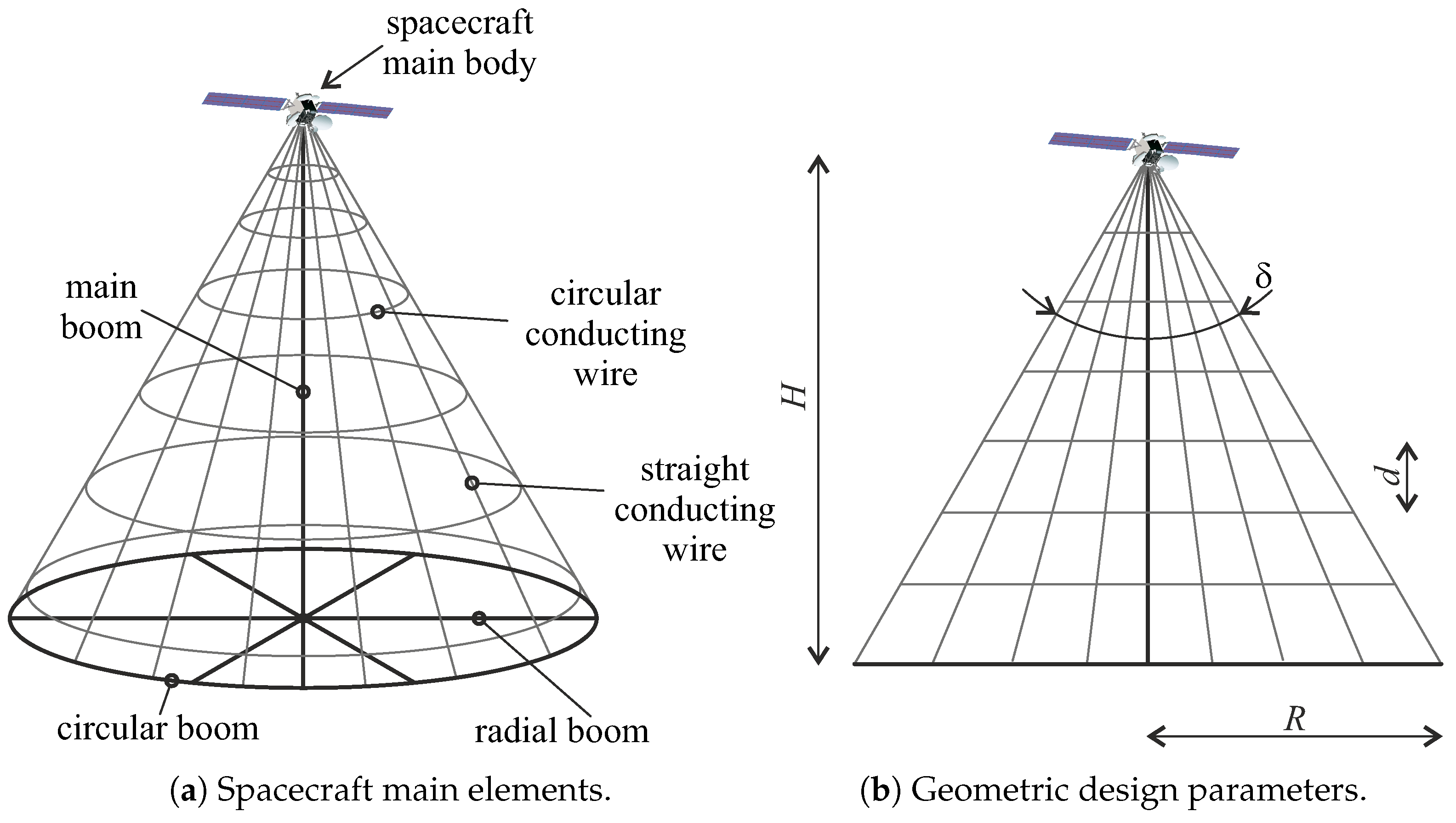
According to Refs. [31,32,33], the SWIFT propulsion system concept consists of a conically-shaped mesh grid of conducting tethers, which are electrostatically charged with a nominal positive voltage ϕ 0 , and a few auxiliary booms, used as supporting structural elements, as illustrated in Figure 2, where δ is the cone aperture angle.
The solar wind dynamic pressure impinging on the conically-shaped mesh grid of the SWIFT produces a propulsive force component D, usually referred to as “drag” because it opposes the Sun’s gravitational pull, which is aligned with the outward radial direction i ^ r (see Figure 1), and given by [34]
D = n sw m p v sw 2 A ,
where n sw and v sw are the local solar wind particle density and bulk velocity, respectively, m p is the proton mass, A π R 2 denotes the SWIFT cone base area, R being the cone’s base radius. The latter is here considered a geometric design parameter. The values of m p and v sw , along with other physical parameters later defined and used in the numerical simulations, are reported in Table 1.
There exists a second contribution to the SWIFT-induced total force [34], that is, the steerable component T of Figure 1, obtained by accelerating the collected solar wind positive ions and then ejecting them in a beam that can be suitably oriented by means of a dedicated assembly. In a two-dimensional mission scenario, the orientation of the ion beam (an so the direction of T) is defined by a single reference angle α , that is, the thrust angle, where α [ α max , α max ] (with α max > 0 ) is measured counterclockwise from i ^ r as illustrated in Figure 1. Note that α is constrained to a maximum ( α max ) and a minimum ( α max ) value by the presence of the conical structure. Bearing in mind the scheme of Figure 2b, the maximum thrust angle cannot exceed π rad δ / 2 , while in the rest of the paper α max is calculated as
α max = π rad δ 2 Δ α ,
where Δ α 0 is a contingency factor that is added to the nominal value of ( π rad δ / 2 ) to account for possible uncertainties on the SWIFT cone geometry. According to Ref. [34], the magnitude of T is given by
T = n sw m p v sw v ex A n sw m p v sw v ex π R 2 ,
where v ex is the ion beam exhaust velocity so that, from Equations (7) and (9), it can be observed that the steerable thrust and the drag are related by the simple relation
T = k D ,
where
k v ex v sw .
In a preliminary mission analysis, the solar wind velocity v sw can be assumed to be practically constant, that is, nearly independent of both r and t. This means that the value of k, defined in Equation (11), may be modified by simply varying the ion beam exhaust velocity v ex . In this sense, k is here considered a propulsive design parameter. Since the particle density n sw scales as the inverse square of the heliocentric distance, that is,
n sw = n r r 2 ,
where r = 1 au is a reference distance and n the solar wind particle density at r = r , the force components D and T may be written in a compact form as
D = D r r 2
T = k D r r 2 ,
where D denotes the value of D calculated at r = r . Note that the previously described model assumes that the solar wind density is stationary, i.e., that it does not fluctuate over time. This simplifying assumption is reasonable in a preliminary mission analysis, although data collected by several space missions [38,39,40] clearly indicate that the plasma parameters undergo chaotic temporal fluctuations. Using Equation (7), the expression of D is
D n m p v sw 2 π R 2 ,
which is a function of the (geometric) design parameter R. To obtain the expressions of the propulsive acceleration components { a r , a θ } in Equation (2), the reference drag force D is rewritten in terms of force-to-mass ratio as
a D D m ,
where m is the total spacecraft mass, here considered as a constant.
The value of m may be estimated with a spacecraft mass breakdown model. To that end, we adopted the original approach reported in Ref. [34], which has been suitably refined and extended. More precisely, the total spacecraft mass is considered as the sum of four contributions, that is,
m = m w + m s + m ps + m b ,
where m w is the total mass of conducting wires, m s is the total mass of supporting booms, m ps is the mass of the power generation subsystem, and m b is the mass of the main spacecraft, including the payload and the other typical subsystems. In this analysis, m b is a sort of inertial design parameter that depends on the characteristics of the scientific mission to be fulfilled. The total mass of the conducting wires composing the (conical) mesh grid is evaluated as
m w = π ρ w r w 2 L w ,
where ρ w is the density of the wire material, r w is the wire radius, and L w is the total length of the conducting wires. The latter is the sum of the total length of the straight wires and the circular wires, viz.
L w = N e R sin ( δ / 2 ) + 2 π d tan ( δ / 2 ) i = 1 N c i ,
where N e and N c are the number of external (straight) and circular conducting wires, respectively, and d is the spacing distance between two consecutive circular wires; see Figure 2. Unlike N e , which is a design parameter, N c is calculated as
N c = ceil R d tan ( δ / 2 ) ,
where ceil ( x ) denotes the ceil function of the argument x, which gives a smaller integer number greater than x.
The second contribution to the total spacecraft mass is given by the structural elements necessary to support the SWIFT, that is, m s . According to Gemmer et al. [31], the supporting structure comprises a main boom, which extends from the spacecraft’s main body to the cone base, a ring-shaped structure around the cone base, and a number N s of auxiliary radial elements connecting the main boom and the base ring; see Figure 2. The total length L s of the supporting structural elements is therefore given by
L s = 2 π R + R tan ( δ / 2 ) + N s R ,
so that
m s = ρ l b L s ,
where ρ l b is the linear mass density of the structural elements. The mass m ps of the power generation subsystem is estimated by writing the total electric power P required by the spacecraft as a function of the design parameters. To this end, two main contributions are accounted for, that is, the electric power P ex used to accelerate the (steerable) ion beam, and the electric power P w required to maintain the conical grid voltage, viz.
P = P ex + P w ,
in which the value of P ex is calculated as
P ex = 1 2 n m p A v sw v ex 2 1 2 n m p π R 2 v sw 3 k 2 ,
while P w is given by
P w = 2 n r w 2 e 3 ϕ 0 3 m e L w ,
where e is the elementary charge, m e is the electron mass, and L w is obtained from Equation (19). Note that the power consumption estimation involves the solar wind ion density at Sun–Earth distance, so it is valid as long as the Sun–spacecraft distance is not too far from 1 au . Finally, the mass of the power generation system m ps is considered a linear function [31] of P through the (assigned) power subsystem specific mass β , that is,
m ps = β P β 1 2 n m p π R 2 v sw 3 k 2 + 2 n r w 2 e 3 ϕ 0 3 m e L w .
Note that, in the right hand side of Equation (26), the dependence on the base radius R also appears in L w ; see Equation (19).
Based on the previous discussion, the two propulsive acceleration components { a r , a θ } can be calculated using Equations (7), (9) and (17), recalling that the drag force component D is radial, while the steerable thrust component T forms an angle α with i ^ r ; see Figure 1. The expressions of { a r , a θ } are therefore
a r = D + T cos α m a D r r 2 ( 1 + k cos α )
a θ = T sin α m a D r r 2 k sin α ,
where a D and k are given by Equations (16) and (11), respectively. The magnitude of the propulsive acceleration vector can be calculated by means of Equations (27) and (28) as
a = a D r r 2 1 + k 2 + 2 k cos α .
Its maximum value, for a given solar distance, is obtained when α = 0 , that is, when T is aligned with the outward radial direction, so that the expression of a max depends on the Sun–spacecraft distance as
a max = a D r r 2 1 + k .
The value of a or a max can be used to obtain the dimensionless version of the propulsive acceleration components as a function of the pair { α , k } , viz.
a r a max = 1 + k cos α 1 + k , a θ a max = k 1 + k sin α
or
a r a = 1 + k cos α 1 + k 2 + 2 k cos α , a θ a = k sin α 1 + k 2 + 2 k cos α .
In this regard, Figure 3 shows the propulsive acceleration, normalized with a max , as a function of k and α .
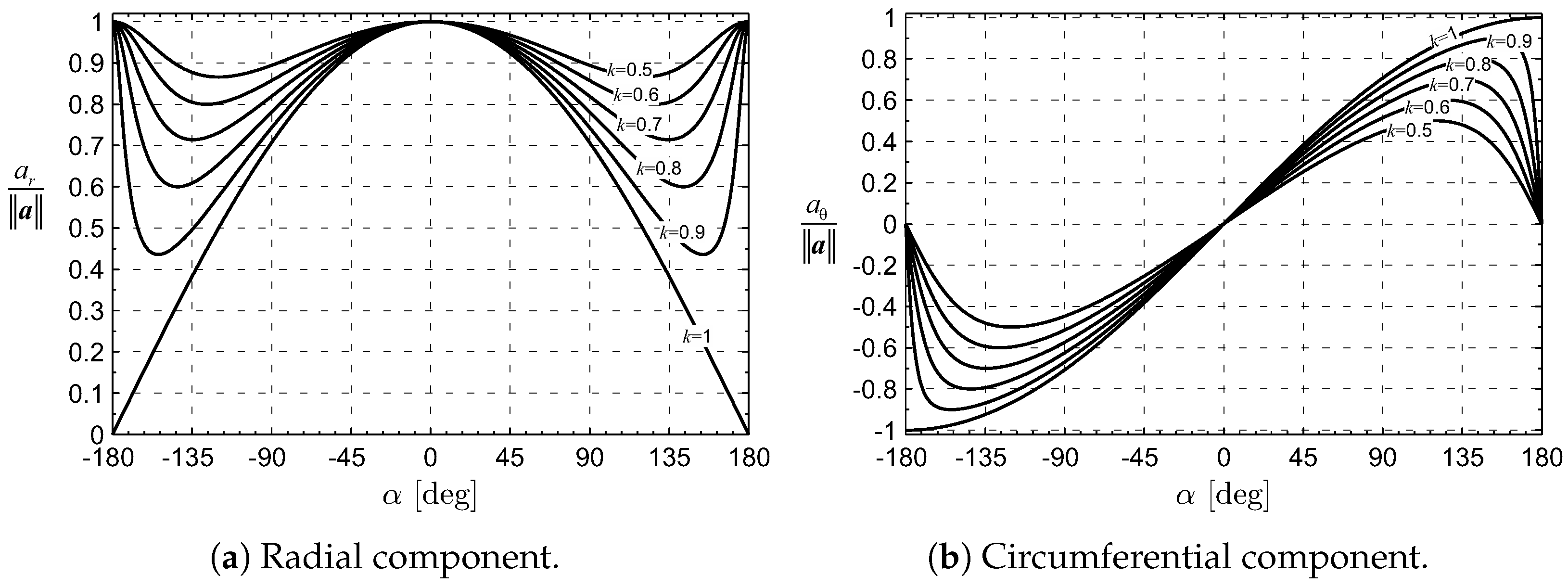
Figure 4, instead, illustrates the dimensionless components of the propulsive acceleration as a function of α for different values of the propulsive parameter k. While the maximum value of a r is obtained with α = 0 , the circumferential component a θ is maximized by values of the thrust angle that vary with the design parameter k.
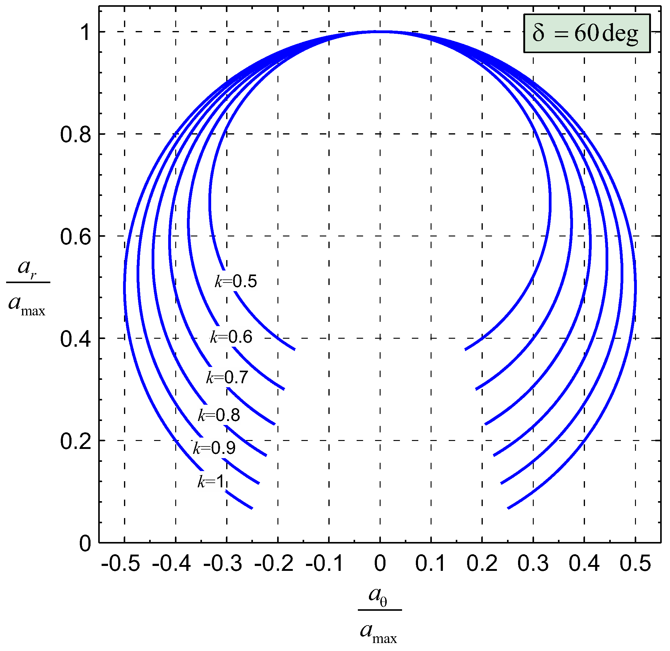
Finally, Figure 5 shows the classical force bubble [41] for different values of k, suggesting that a larger value of k may provide a larger circumferential component of the propulsive acceleration, with the drawback of a corresponding necessary increase of the required power for ion acceleration, as shown by Equation (24). Note that Figure 5 takes into account the presence of a conical grid with aperture angle δ = 60 deg and a contingency Δ α = 0 , thus implying that the thrust angle ranges in the interval α [ 150 , 150 ] deg .
From the viewpoint of interplanetary transfer performance, the possibility of generating a significant value of circumferential acceleration a θ is of primary concern. In this regard, from Equation (28), the maximum value of a θ is reached when α = 90 deg and is given by
max a θ = a D r r 2 k .
Bearing in mind Equation (31), it is found that
max a θ a max = k 1 + k .
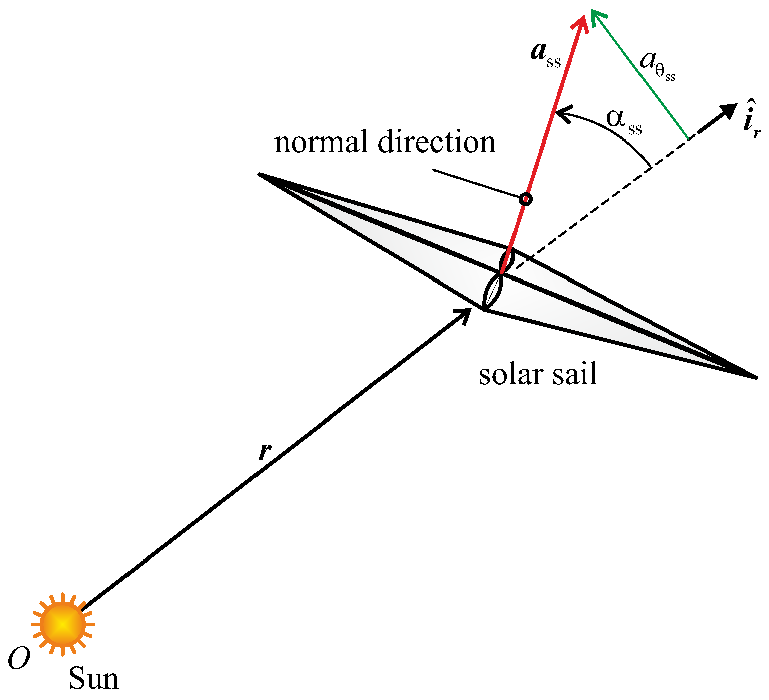
The preceding equation allows us to compare the thrust capabilities of the SWIFT concept and that of an ideal (i.e., perfectly reflecting) flat solar sail in terms of the dimensionless ratio max a θ / a max . In fact, in an ideal solar sail (subscript ss), the circumferential component of the propulsive acceleration can be written as [16]
a θ ss = a max ss sin α ss cos 2 α ss ,
where α ss is the angle between the sail thrust vector (whose direction coincides with that of the unit vector normal to the sail-shaded plane [42]) and the radial direction, while a max ss is the (local) maximum propulsive acceleration magnitude obtained in a Sun-facing condition [43]; see Figure 6.
The value of max a θ ss / a max ss is reached when α ss = arcsin ( 1 / 3 ) , with
max a θ ss a max ss = 2 3 3 .
Equating the right hand sides of Equations (34) and (36), one obtains the value of k necessary for the SWIFT thruster to be equal to the dimensionless circumferential component of the solar sail-induced acceleration, that is,
k = k = 2 3 3 2 0.6258 .
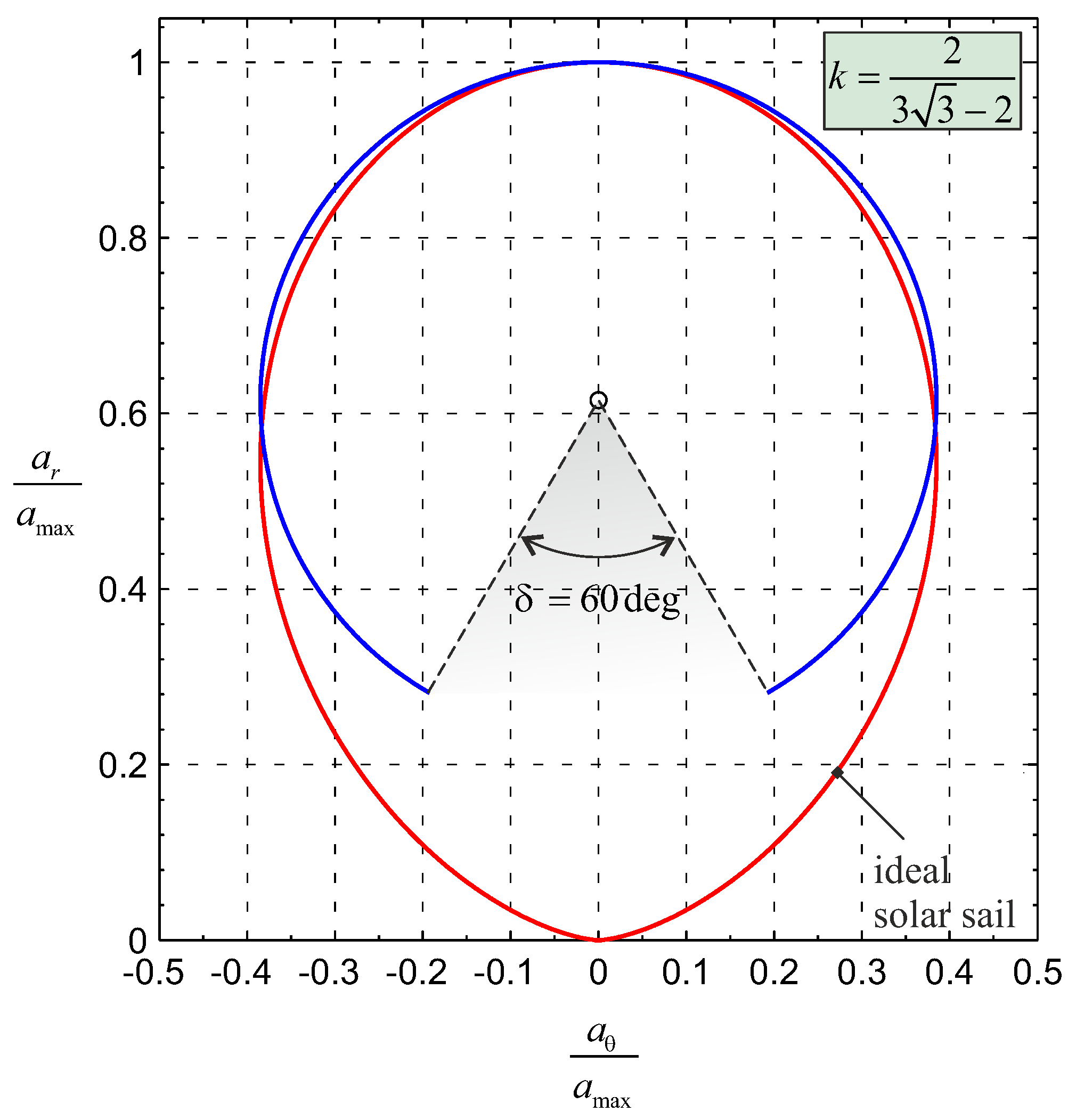
As a result, when k > k , the maximum value of a θ for a SWIFT-based spacecraft is greater than the corresponding value of an ideal solar sail of equal a max . In the special case when k = k , δ = 60 deg and Δ α = 0 , Figure 7 compares the force bubbles of the two propulsion systems.
With the aid of Equations (27) and (28), the last two equations of motion (5) and (6) become
v ˙ r = v θ 2 r μ r 2 + a D r r 2 ( 1 + k cos α )
v ˙ θ = v r v θ r + a D r r 2 k sin α ,
in which the thrust angle α is the control variable, while a D and k may be thought of as the design parameters that define the propulsive performance of the SWIFT system. For a given pair { a D , k } , the time variation of the thrust angle α = α ( t ) is obtained as the solution of an optimal control problem in which the transfer trajectory minimizes the flight time between the parking and the target orbit, as discussed in the next section.

3. Trajectory Optimization

Consider a circle-to-circle (coplanar) orbit transfer, where the SWIFT-based spacecraft, which initially (at t 0 = 0 ) tracks a heliocentric circular orbit of radius r 0 r ( t 0 ) = r , reaches a target circular orbit of given radius r f r ( t f ) at time t f . It is assumed that at time t 0 the spacecraft leaves the Earth along a parabolic (escape) orbit. In addition, without loss of generality, the spacecraft’s initial polar angle is set equal to zero, while the final value of θ is left free, that is, it is an output of the optimization process. Accordingly, the initial and final constraints on the spacecraft state variables { r , θ , v r , v θ } are
r ( t 0 ) = r , θ ( t 0 ) = 0 , v r ( t 0 ) = 0 , v θ ( t 0 ) = μ r
r ( t f ) = r f , v r ( t f ) = 0 , v θ ( t f ) = μ r f .
The orbit transfer is analyzed in an optimal framework [44,45,46], in which the trajectory is found by minimizing the flight time necessary for the spacecraft to reach the target orbit. This amounts to maximizing the performance index
J t f ,
where t f coincides with the total flight time to be calculated. The optimal control problem is faced with an indirect approach [47,48], in which the Hamiltonian H is obtained from Equations (3), (4), (38) and (39) as
H = λ r v r + λ θ v θ + λ v r v θ 2 r μ r 2 + a D r r 2 ( 1 + k cos α ) + + λ v θ v r v θ r + a D r r 2 k sin α ,
where { λ r , λ θ , λ v r , λ v θ } are the variables adjoint to the spacecraft states. The time variation of the adjoint variables is described by the Euler–Lagrange equations [47,48],
λ ˙ r = H r , λ ˙ θ = H θ , λ ˙ v r = H v r , λ ˙ v θ = H v θ ,
whose explicit expressions are here omitted for the sake of brevity. It can be easily verified that λ ˙ θ = 0 (in fact H does not explicitly depend on the polar angle), so that λ θ is a constant of motion. Its value is found from the transversality condition that, in this case, reads
λ θ ( t f ) = 0 , H ( t f ) = 1 ,
from which λ θ = 0 during the whole flight.
The optimal control law α = α ( t ) , that is, the optimal time variation of the thrust angle, comes from the Pontryagin’s maximum principle [48], according to which α must maximize the Hamiltonian at any time instant. Observing from Equation (43) that
H a D k r r 2 λ v r cos α + λ v θ sin α
coincides with that part of H that explicitly depends on α , and recalling that the thrust angle modulus is upper constrained by α max of Equation (8), the optimal control law is found to be
α = α max i f   σ > α max α max i f   σ < α max σ otherwise ,
where σ ( π , π ] rad is an auxiliary angle defined as
sin σ λ v θ λ v θ 2 + λ v r 2 , cos σ λ v r λ v θ 2 + λ v r 2 .
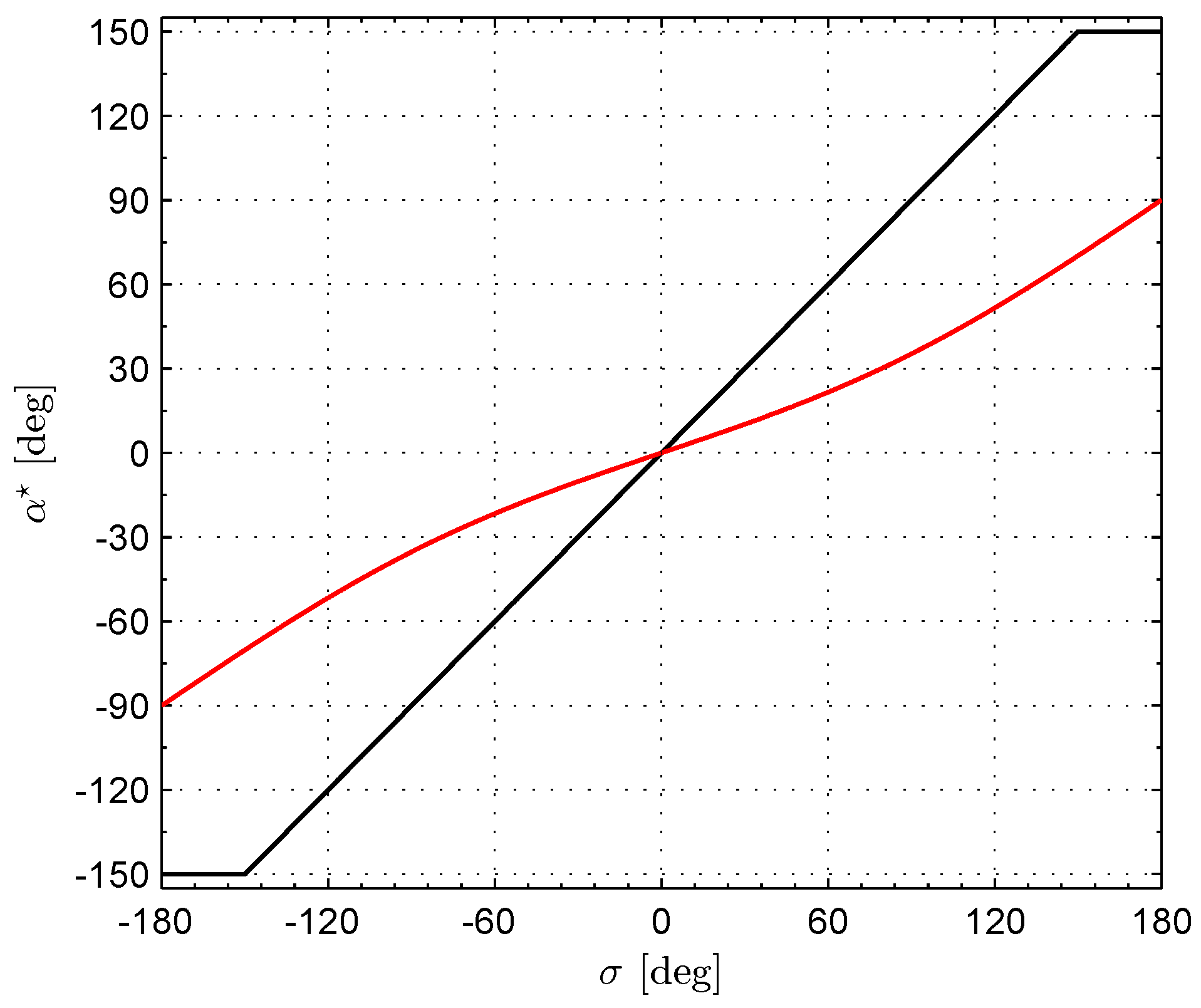
The optimal control law for a SWIFT system is different from that of an ideal solar sail. This is clearly shown in Figure 8, which, with the aid of Sauer’s results [37], compares the optimal thrust angle as a function of σ for an ideal solar sail and a SWIFT propulsion system with an aperture angle δ = 60 deg and a contingency Δ α = 0 .
The associated two-point boundary value problem is described by the eight differential Equations (3), (4), (38), (39) and (44) with the eight boundary conditions given by Equations (40) and (41) and the first of Equation (45), while the last of Equation (45) allows the minimum flight time to be calculated. The two-point boundary value problem has been solved with a hybrid numerical technique that combines genetic algorithms with gradient-based methods [49]. The next section analyzes the results obtained by numerically solving the optimal control problem in a pair of typical mission scenarios.

4. Numerical Simulations and Mission Applications

The previous SWIFT thrust model is now used to evaluate the spacecraft propulsive performance for a given set of design parameters. To that end, we use the main assumptions made in the original work by Gemmer et al. [34], with a few changes. More precisely, the main differences between the data reported in Table 2 and those indicated in Ref. [34] are the values of { d , N s } that were originally chosen as { 1 m , 1 } . In addition, recall that in this work the thrust model accounts for the presence of a sort of “payload” mass term (which coincides with the term m b in the current notation), a contingency angle Δ α , and a maximum thrust angle constraint, which are not considered in the simplified model discussed in Ref. [34].
The design parameters of the SWIFT-based spacecraft are summarized in Table 2, where the main spacecraft mass m b is assumed to be 250 kg , while β is a trade-off value between flight-qualified solar panels (i.e., 10 3 kg / W ) and cutting-edge photovoltaic (i.e., 5 × 10 2 kg / W ) [34,50]. Using these design parameters, the spacecraft characteristics and its propulsive performance are those detailed in Table 3. In particular, according to Equation (8), the assumed values of δ and Δ α provide α max = 90 deg , so that the steerable propulsive force T has a non-negative radial component, as happens in a typical solar sail [16] or E-sail [22] mission scenario. This aspect is highlighted in Figure 9, which shows the SWIFT force bubble used in the numerical simulations at a distance r = r from the Sun. Note that, according to Equation (11), the value k = 1 gives a steerable thrust magnitude equal to D and an exhaust velocity of 400 km / s . The assumed value of v ex is well above the current typical range, but it is consistent with the recent development in the area of electric propulsion systems [51]. Figure 9 shows that in this case the maximum radial acceleration a r is equal to twice the maximum transverse component a θ .

Case Study

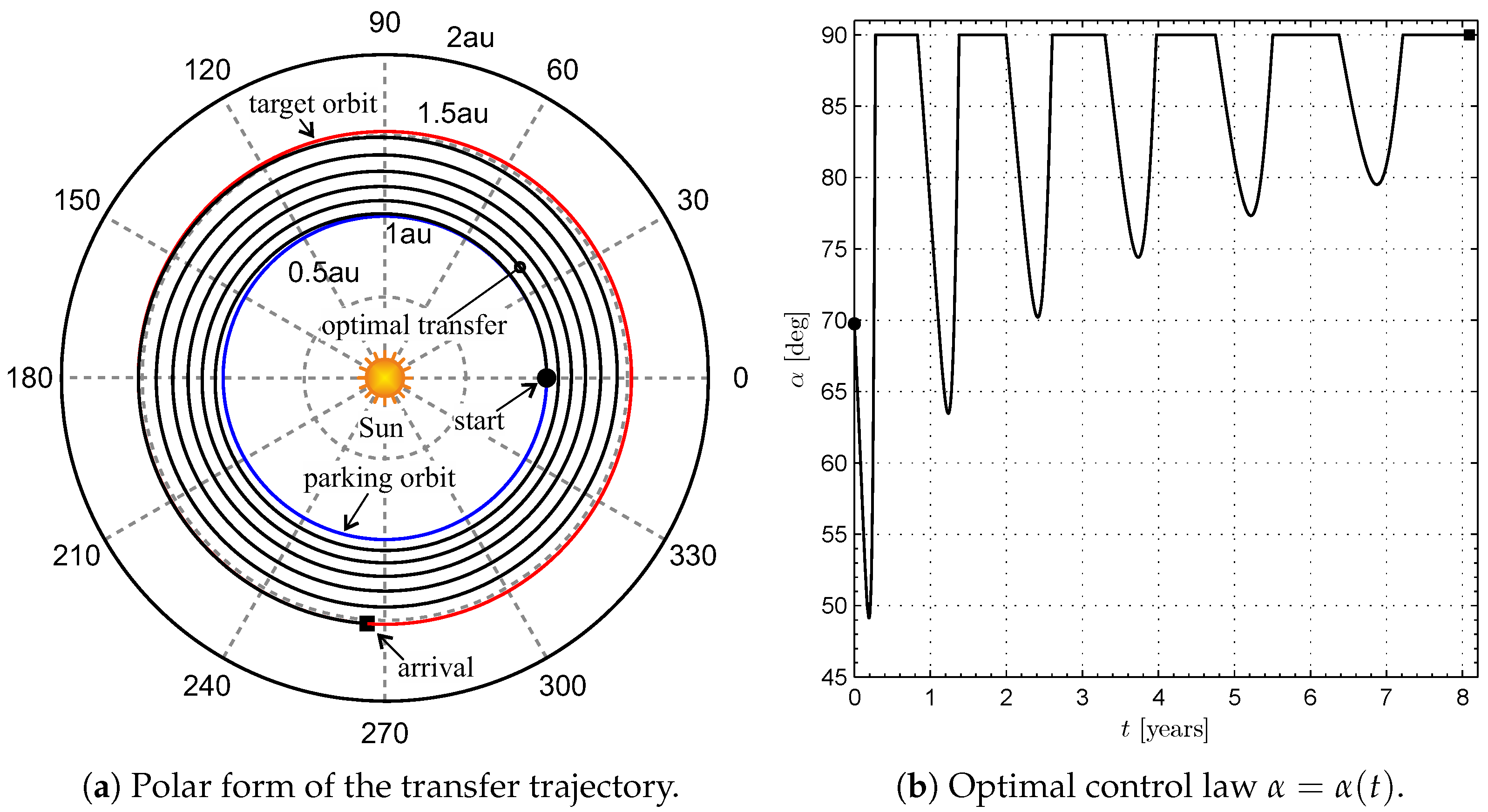
Two specific mission applications are considered to estimate the optimal performance of a SWIFT-based spacecraft, the main characteristics of which are detailed in Table 3. In particular, an orbit raising with r f = r 1.524 au , and an orbit lowering with r f = r 0.723 au have been studied. Recalling that the radius of the initial circular orbit is r 0 = r = 1 au , the case of r f = r (or r f = r ) is representative of a simplified, ephemeris-free, Earth–Mars (or Earth–Venus) interplanetary transfer in which the eccentricity and the inclination over the Ecliptic of both planetary orbits are neglected. The results of the numerical optimization for the Earth–Mars transfer give a minimum flight time that is slightly shorter than 8.1 years , with an optimal transfer trajectory that completes five revolutions around the Sun before reaching the target Mars orbit. This aspect is confirmed by Figure 10a, which shows the optimal transfer trajectory in a polar reference frame. According to Figure 10b, which shows the optimal time variation of the thrust angle, α reaches six times the maximum value α max with a mean value (over the entire transfer) of about 84 deg .
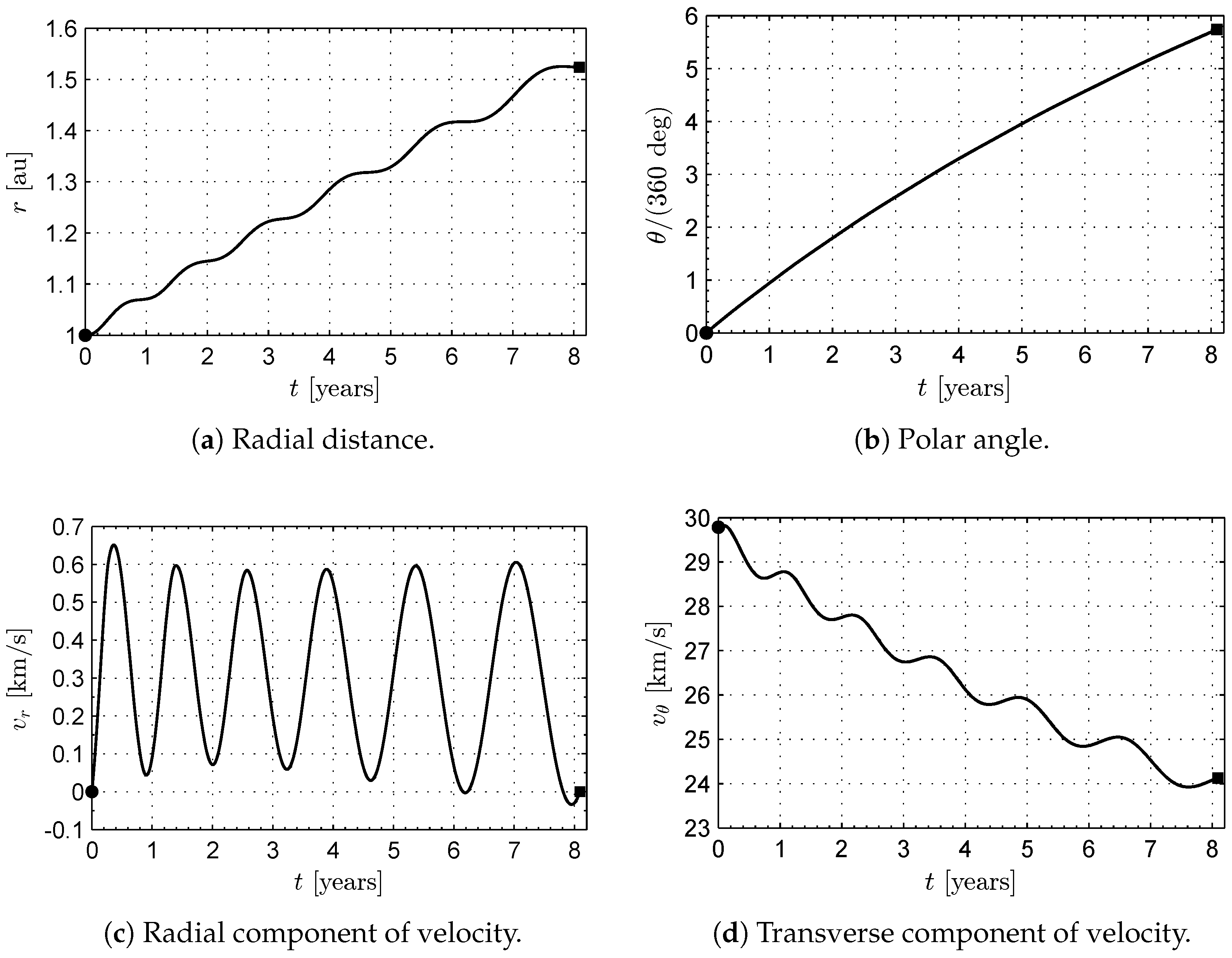
The time variations of the spacecraft states { r , θ , v r , v θ } are reassumed in Figure 11. Note that the radial spacecraft velocity v r remains small during the whole transfer, so that the optimal transfer trajectory can be approximated with a sort of tight spiral connecting the initial and final (circular) orbits. This feature of the transfer trajectory is the result of a propulsive acceleration that is small, in comparison with the (local) Sun’s gravitational acceleration. Figure 11 also shows that the time variation of the Sun–spacecraft distance r (or the transverse component of the inertial spacecraft velocity v θ ) may be thought of as a superposition of a secular increase (or decrease) and a short period of oscillation. As a result, the SWIFT system’s performance is similar to that obtained using a solar sail [52,53,54], an E-sail [25], a Heliogyro [55], or a low-performance electric thruster [56,57] as a primary propulsion system.
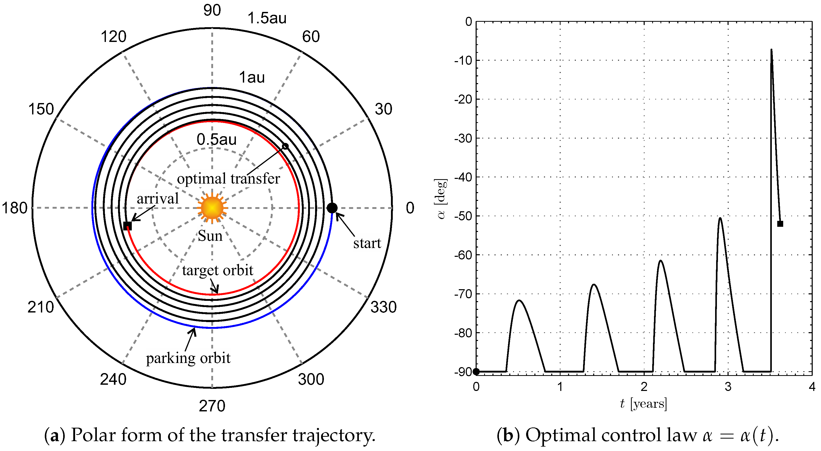
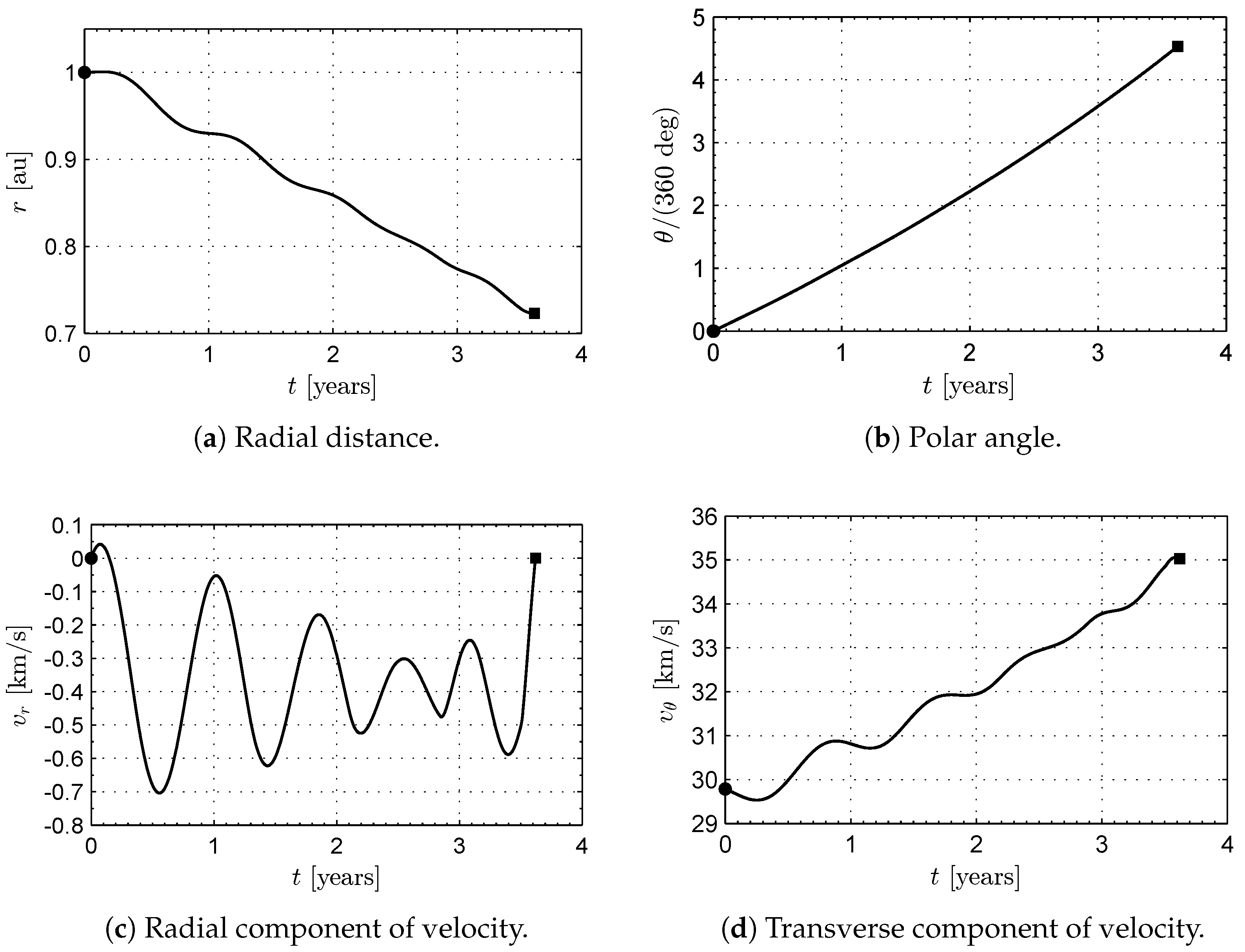
Similar considerations can be made for an Earth–Venus transfer (when r f = r ), which is completed with a flight time of slightly above 3.6 years . In that case, the optimal transfer trajectory and the time variation of the thrust angle are shown in Figure 12, while the spacecraft states are reassumed in Figure 13. Note that α < 0 during the entire transfer, that is, the steerable thrust T has a negative circumferential component. In that case, the value of α max is reached five times, with a mean value of the thrust angle of about 80 deg .

5. Conclusions

This paper has analyzed the performance of a SWIFT-based spacecraft in a heliocentric and two-dimensional mission scenario. In particular, an improved version of the thrust vector mathematical model has been discussed with the aim of obtaining a set of analytical equations useful for a preliminary trajectory analysis. The optimal control law has been obtained with an indirect approach, and the corresponding two-point boundary value problem has been solved using a hybrid numerical technique. The numerical results show that the typical propulsive performance of a SWIFT-based spacecraft, in a simplified interplanetary trajectory, provides a minimum flight time of some years for a mission towards Mars (or Venus) without ephemeris constraints. These numbers, which are comparable to more conventional propellantless systems such as solar sails or E-sails, prevents the use of this propulsion concept from a manned interplanetary mission, as expected. However, the intrinsic characteristic of a SWIFT propeller of providing a continuous thrust for a long period of time allows this propulsion system to be an interesting option in advanced high-energy missions such as the generation of artificial equilibrium points or displaced non-Keplerian orbits. These two latter applications are the focus of our current research and represent the natural extension of this work.

Author Contributions

Conceptualization, A.A.Q.; methodology, A.A.Q.; software, A.A.Q. and L.N.; writing—original draft preparation, A.A.Q. and L.N.; writing—review and editing, G.M. and M.B. All authors have read and agreed to the published version of the manuscript.

Funding

This work is partly supported by the University of Pisa, Progetti di Ricerca di Ateneo (Grant no. PRA_2022_1).

Institutional Review Board Statement

Not applicable.

Informed Consent Statement

Not applicable.

Data Availability Statement

Not applicable.

Conflicts of Interest

The authors declare no conflict of interest.

Abbreviations

Notation
ASWIFT cone base area [m 2 ]
a D design parameter; see Equation (16) [mm/s 2 ]
a propulsive acceleration vector [mm/s 2 ]
a max maximum propulsive acceleration magnitude [mm/s 2 ]
a r radial component of a [mm/s 2 ]
a θ transverse component of a [mm/s 2 ]
Dradial thrust (“drag”) [N]
dspacing between circular conducting wires [m]
eelementary charge [C]
HSWIFT cone height [m]
H Hamiltonian
kdimensionless design parameter; see Equation (11)
k critical value of k; see Equation (37)
i ^ r radial unit vector
i ^ θ circumferential unit vector
Jperformance index
L s total length of structural elements [m]
L w total length of conducting wires [m]
mtotal spacecraft mass [kg]
m b spacecraft main body mass [kg]
m e electron mass [kg]
m p proton mass [kg]
m ps SWIFT power generation system mass [kg]
m s SWIFT structure mass [kg]
m w SWIFT wires total mass [kg]
N c number of circular conducting wires
N e number of straight conducting wires
N s number of radial support booms
n sw solar wind density [particles/m 3 ]
n value of n sw at 1 au from the Sun
OSun’s center of mass
Ptotal power required by the SWIFT [W]
P ex power required by ion acceleration [W]
P w power required by wire grid [W]
RSWIFT cone base radius [m]
rSun-spacecraft radial distance [au]
r spacecraft position vector [au]
r w conducting wire radius [m]
r reference distance [ 1 au ]
Tsteerable thrust [N]
ttime [days]
T polar reference frame
v spacecraft velocity vector [km/s]
v r radial component of the spacecraft velocity [km/s]
v sw solar wind velocity [km/s]
v ex exhaust velocity [km/s]
v θ transverse component of the spacecraft velocity [km/s]
α thrust angle [deg]
α optimal thrust angle [deg]
Δ α contingency value [deg]
β power system specific mass [kg/W]
δ SWIFT cone aperture [deg]
ϕ 0 conducting wire electric potential [V]
λ r variable adjoint to r
λ v r variable adjoint to v r
λ v θ variable adjoint to v θ
λ θ variable adjoint to θ
μ Sun’s gravitational parameter [km 3 /s 2 ]
ρ l b support boom linear density [kg/m]
ρ w conducting wire density [kg/m 3 ]
θ spacecraft polar angle [deg]
Subscripts
0initial, parking orbit
ffinal, target orbit
Mars
Venus
ssideal flat solar sail

References

  1. Jacobson, R.A.; Thornton, C.L. Elements of solar sail navigation with application to a Halley’s comet rendezvous. J. Guid. Control Dyn. 1978, 1, 365–371. [Google Scholar] [CrossRef]
  2. Quarta, A.A.; Mengali, G.; Janhunen, P. Electric sail option for cometary rendezvous. Acta Astronaut. 2016, 127, 684–692. [Google Scholar] [CrossRef]
  3. Hughes, G.W.; McInnes, C.R. Small-body encounters using solar sail propulsion. J. Spacecr. Rocket. 2004, 41, 140–150. [Google Scholar] [CrossRef]
  4. Quarta, A.A.; Mengali, G.; Janhunen, P. Electric sail for a near-Earth asteroid sample return mission: Case 1998 KY26. J. Aerosp. Eng. 2014, 27, 4014031. [Google Scholar] [CrossRef]
  5. Slavinskis, A.; Janhunen, P.; Toivanen, P.; Muinonen, K.; Penttilä, A.; Granvik, M.; Kohout, T.; Gritsevich, M.; Pajusalu, M.; Sunter, I.; et al. Nanospacecraft fleet for multi-asteroid touring with electric solar wind sails. In Proceedings of the IEEE Aerospace Conference, Big Sky, MT, USA, 3–10 March 2018; pp. 1–20. [Google Scholar] [CrossRef]
  6. Dandouras, I.; Pirard, B.; Prado, J.Y. High performance solar sails for linear trajectories and heliostationary missions. Adv. Space Res. 2004, 34, 198–203. [Google Scholar] [CrossRef]
  7. Quarta, A.A.; Mengali, G. Optimal solar sail transfer to linear trajectories. Acta Astronaut. 2013, 82, 189–196. [Google Scholar] [CrossRef]
  8. Gong, S.; Li, J. Solar sail heliocentric elliptic displaced orbits. J. Guid. Control Dyn. 2014, 37, 2021–2025. [Google Scholar] [CrossRef]
  9. Niccolai, L.; Quarta, A.A.; Mengali, G. Electric sail elliptic displaced orbits with advanced thrust model. Acta Astronaut. 2017, 138, 503–511. [Google Scholar] [CrossRef]
  10. Niccolai, L.; Anderlini, A.; Mengali, G.; Quarta, A.A. Electric sail displaced orbit control with solar wind uncertainties. Acta Astronaut. 2019, 162, 563–573. [Google Scholar] [CrossRef]
  11. Bassetto, M.; Quarta, A.A.; Mengali, G. Magnetic sail-based displaced non-Keplerian orbits. Aerosp. Sci. Technol. 2019, 92, 363–372. [Google Scholar] [CrossRef]
  12. Aliasi, G.; Mengali, G.; Quarta, A.A. Artificial equilibrium points for a generalized sail in the circular restricted three-body problem. Celest. Mech. Dyn. Astron. 2011, 110, 343–368. [Google Scholar] [CrossRef] [Green Version]
  13. Niccolai, L.; Caruso, A.; Quarta, A.A.; Mengali, G. Artificial collinear Lagrangian point maintenance with electric solar wind sail. IEEE Trans. Aerosp. Electron. Syst. 2020, 56, 4467–4477. [Google Scholar] [CrossRef]
  14. Bianchi, C.; Niccolai, L.; Mengali, G.; Quarta, A.A. Collinear artificial equilibrium point maintenance with a wrinkled solar sail. Aerosp. Sci. Technol. 2021, 119, 1–14. [Google Scholar] [CrossRef]
  15. Zeng, X.; Gong, S.; Li, J.; Alfriend, K.T. Solar sail body-fixed hovering over elongated asteroids. J. Guid. Control Dyn. 2016, 39, 1223–1231. [Google Scholar] [CrossRef]
  16. McInnes, C.R. Solar Sailing: Technology, Dynamics and Mission Applications; Springer: Berlin, Germany, 1999; pp. 171–196. [Google Scholar] [CrossRef]
  17. Fu, B.; Sperber, E.; Eke, F. Solar sail technology—A state of the art review. Prog. Aerosp. Sci. 2016, 86, 1–19. [Google Scholar] [CrossRef]
  18. Bovesecchi, G.; Corasaniti, S.; Costanza, G.; Tata, M.E. A novel self-deployable solar sail system activated by shape memory alloys. Aerospace 2019, 6, 78. [Google Scholar] [CrossRef] [Green Version]
  19. Zhang, F.; Gong, S.; Baoyin, H. Three-axes attitude control of solar sail based on shape variation of booms. Aerospace 2021, 8, 198. [Google Scholar] [CrossRef]
  20. Zou, J.; Li, D.; Wang, J.; Yu, Y. Experimental study of measuring the wrinkle of solar sails. Aerospace 2022, 9, 289. [Google Scholar] [CrossRef]
  21. Janhunen, P. Electric sail for spacecraft propulsion. J. Propuls. Power 2004, 20, 763–764. [Google Scholar] [CrossRef]
  22. Bassetto, M.; Niccolai, L.; Quarta, A.A.; Mengali, G. A comprehensive review of Electric Solar Wind Sail concept and its applications. Prog. Aerosp. Sci. 2022, 128, 100768. [Google Scholar] [CrossRef]
  23. Huo, M.Y.; Mengali, G.; Quarta, A.A. Electric sail thrust model from a geometrical perspective. J. Guid. Control Dyn. 2018, 41, 735–741. [Google Scholar] [CrossRef]
  24. Bassetto, M.; Quarta, A.A.; Mengali, G.; Cipolla, V. Spiral trajectories induced by radial thrust with applications to generalized sails. Astrodynamics 2020, 5, 121–137. [Google Scholar] [CrossRef]
  25. Quarta, A.A.; Mengali, G.; Bassetto, M.; Niccolai, L. Optimal circle-to-ellipse orbit transfer for Sun-facing E-sail. Aerospace 2022, 9, 671. [Google Scholar] [CrossRef]
  26. Forward, R.L. Solar Photon Thrustor. J. Spacecr. Rocket. 1990, 27, 411–416. [Google Scholar] [CrossRef]
  27. Mengali, G.; Quarta, A.A. Earth escape by ideal sail and solar-photon thrustor spacecraft. J. Guid. Control Dyn. 2004, 27, 1105–1108. [Google Scholar] [CrossRef]
  28. Mengali, G.; Quarta, A.A. Time-optimal three-dimensional trajectories for solar photon thruster spacecraft. J. Spacecr. Rocket. 2005, 42, 379–381. [Google Scholar] [CrossRef]
  29. Mengali, G.; Quarta, A.A. Compound solar sail with optical properties: Models and performance. J. Spacecr. Rocket. 2006, 43, 239–245. [Google Scholar] [CrossRef]
  30. Fieseler, P.; Anderson, K.R.; Cable, V. Critical look at the solar photon thruster concept. J. Spacecr. Rocket. 2015, 52, 1152–1162. [Google Scholar] [CrossRef]
  31. Gemmer, T.R.; Mazzoleni, A.P. Introduction and Performance Analysis of the Solar Wind Ion Focusing Thruster (SWIFT). In Proceedings of the 65th International Astronautical Congress, Toronto, ON, Canada, 29 September–3 October 2014. Paper IAC-14,C4,8,1,x24646. [Google Scholar]
  32. Gemmer, T.R.; Mazzoleni, A.P. Solar wind ion focusing thruster (SWIFT) Orbital Performance Analysis. In Proceedings of the 66th International Astronautical Congress, Jerusalem, Israel, 12–16 October 2015. [Google Scholar]
  33. Gemmer, T.R.; Mazzoleni, A.P. Comparative orbital performance study of a solar wind ion focusing thruster (SWIFT). In Proceedings of the 67th International Astronautical Congress, Guadalajara, Mexico, 26–30 September 2016. Paper IAC-16,C4,8,8,x33664. [Google Scholar]
  34. Gemmer, T.R.; Yoder, C.D.; Mazzoleni, A.P. Performance Analysis and Parametric Studies of the Solar Wind Ion Focusing Thruster (SWIFT) for Interplanetary Travel. J. Br. Interplanet. Soc. 2021, 74, 30–40. [Google Scholar]
  35. Ross, I.M. A Primer on Pontryagin’s Principle in Optimal Control; Collegiate Publishers: San Francisco, CA, USA, 2015; Chapter 2; pp. 127–129. ISBN 9780984357116. [Google Scholar]
  36. Lawden, D.F. Optimal Trajectories for Space Navigation; Butterworths & Co.: London, UK, 1963; pp. 54–60. [Google Scholar]
  37. Sauer, C.G., Jr. Optimum Solar-Sail Interplanetary Trajectories. In Proceedings of the AIAA/AAS Astrodynamics Conference, San Francisco, CA, USA, 18–20 August 1976. [Google Scholar] [CrossRef]
  38. Gallana, L.; Fraternale, F.; Fosson, S.M.; Magli, E.; Opher, M.; Richardson, J.D.; Tordella, D. Voyager 2 solar plasma and magnetic field spectral analysis for intermediate data sparsity. J. Geophys. Res. A Space Phys. 2016, 121, 3905–3919. [Google Scholar] [CrossRef] [Green Version]
  39. Phillips, J.L.; Bame, S.J.; Barnes, A.; Barraclough, B.M.; Feldman, W.C.; Goldstein, B.E. Ulysses solar wind plasma observations from pole to pole. Geophys. Res. Lett. 1995, 22, 3301–3304. [Google Scholar] [CrossRef]
  40. Stone, E.C.; Frandsen, A.M.; Mewaldt, R.A.; Christian, E.R.; Margolies, D.; Ormes, J.F. The Advanced Composition Explorer. Space Sci. Rev. 1998, 86, 1–22. [Google Scholar] [CrossRef]
  41. Mengali, G.; Quarta, A.A.; Circi, C.; Dachwald, B. Refined solar sail force model with mission application. J. Guid. Control Dyn. 2007, 30, 512–520. [Google Scholar] [CrossRef] [Green Version]
  42. Wright, J.L. Space Sailing; Gordon and Breach Science Publishers: Amsterdam, The Netherlands, 1992. [Google Scholar]
  43. Bassetto, M.; Quarta, A.A.; Mengali, G.; Cipolla, V. Trajectory analysis of a Sun-facing solar sail with optical degradation. J. Guid. Control Dyn. 2020, 43, 1727–1732. [Google Scholar] [CrossRef]
  44. Antonakis, A.; Nikolaidis, T.; Pilidis, P. Multi-objective climb path optimization for aircraft/engine integration using particle swarm optimization. Appl. Sci. 2017, 7, 469. [Google Scholar] [CrossRef] [Green Version]
  45. Morante, D.; Sanjurjo Rivo, M.; Soler, M. A Survey on Low-Thrust Trajectory Optimization Approaches. Aerospace 2021, 8, 88. [Google Scholar] [CrossRef]
  46. Jia, F.; Peng, Q.; Zhou, W.; Li, X. Integrated design of Moon-to-Earth transfer trajectory considering re-entry constraints. Appl. Sci. 2022, 12, 8716. [Google Scholar] [CrossRef]
  47. Bryson, A.E.; Ho, Y.C. Applied Optimal Control; Hemisphere Publishing Corporation: New York, NY, USA, 1975; Chapter 2; pp. 71–89. ISBN 0-891-16228-3. [Google Scholar]
  48. Stengel, R.F. Optimal Control and Estimation; Dover Publications, Inc.: New York, NY, USA, 1994; pp. 222–254. [Google Scholar]
  49. Mengali, G.; Quarta, A.A. Optimal three-dimensional interplanetary rendezvous using nonideal solar sail. J. Guid. Control Dyn. 2005, 28, 173–177. [Google Scholar] [CrossRef]
  50. Shiu, K.T.; Zimmerman, J.; Wang, H.; Forrest, S.R. Ultrathin film, high specific power InP solar cells on flexible plastic substrates. Appl. Phys. Lett. 2009, 95, 223503. [Google Scholar] [CrossRef]
  51. Brophy, J.R.; Polk, J.E.; Goebel, D.M. Development of a 50,000-s, Lithium-fueled, Gridded Ion Thruster. In Proceedings of the 35th International Electric Propulsion Conference, Atlanta, GA, USA, 8–15 October 2017. Paper IEPC-2017-042. [Google Scholar]
  52. Caruso, A.; Quarta, A.A.; Mengali, G. Comparison Between Direct and Indirect Approach to Solar Sail Circle-to-circle Orbit Raising Optimization. Astrodynamics 2019, 3, 273–284. [Google Scholar] [CrossRef]
  53. Quarta, A.A.; Mengali, G. Approximate Solutions to Circle-to-Circle Solar Sail Orbit Transfer. J. Guid. Control Dyn. 2013, 36, 1866–1890. [Google Scholar] [CrossRef]
  54. Quarta, A.A.; Mengali, G. Semi-Analytical Method for the Analysis of Solar Sail Heliocentric Orbit Raising. J. Guid. Control Dyn. 2012, 35, 330–335. [Google Scholar] [CrossRef]
  55. Bassetto, M.; Quarta, A.A.; Caruso, A.; Mengali, G. Optimal heliocentric transfers of a Sun-facing heliogyro. Aerosp. Sci. Technol. 2021, 119, 107094. [Google Scholar] [CrossRef]
  56. Mengali, G.; Quarta, A.A. Trajectory design with hybrid low-thrust propulsion system. J. Guid. Control Dyn. 2007, 30, 419–426. [Google Scholar] [CrossRef]
  57. Mengali, G.; Quarta, A.A. Optimal trade studies of interplanetary electric propulsion missions. Acta Astronaut. 2008, 62, 657–667. [Google Scholar] [CrossRef]
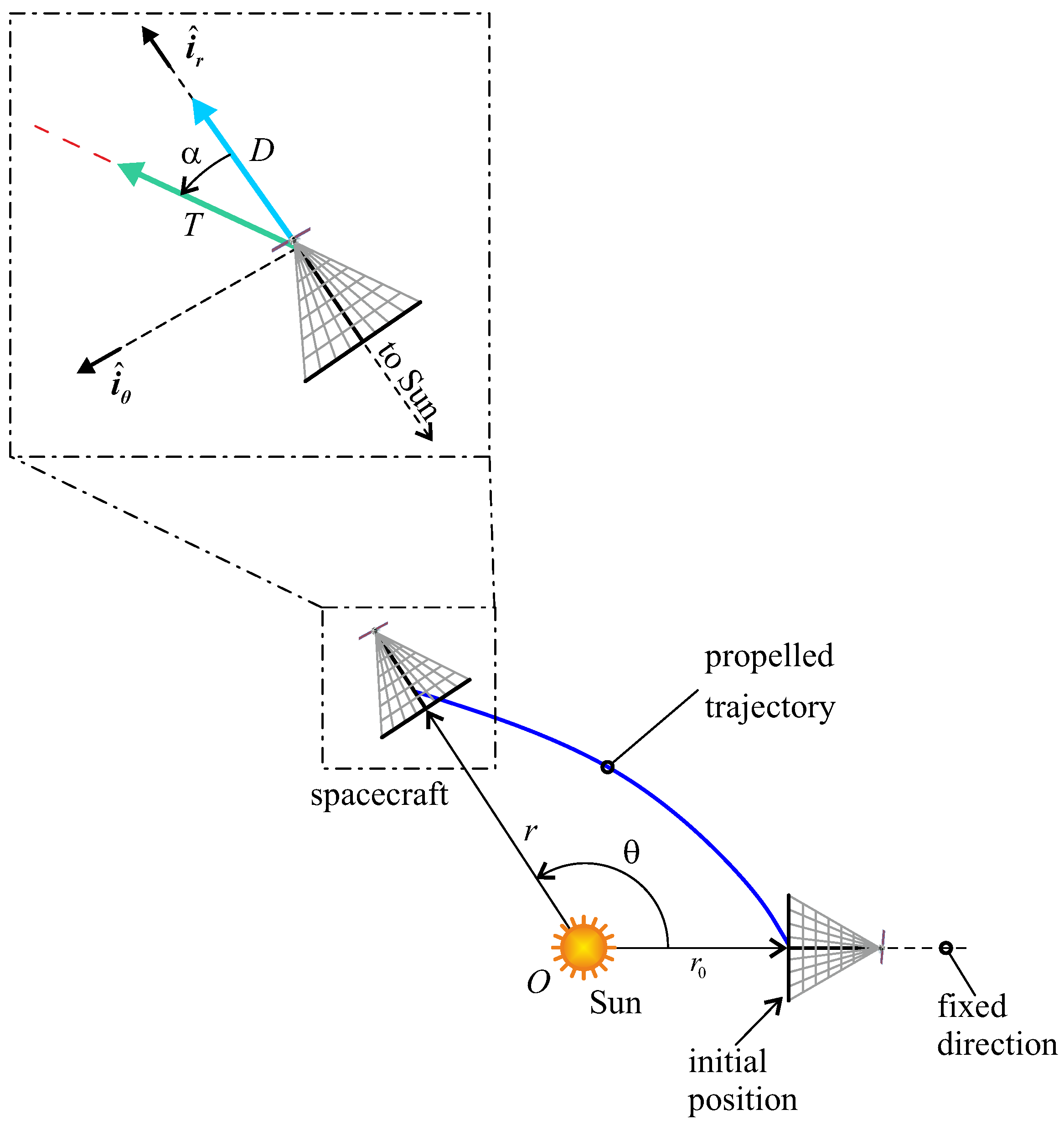
Figure 1. Sketch of the polar reference frame and SWIFT-induced thrust contributions.
Applsci 13 03820 g001
Figure 2. Conceptual scheme of a SWIFT-based spacecraft (main body not to scale).
Applsci 13 03820 g002
Figure 3. Dimensionless propulsive acceleration magnitude as a function of α and k.
Applsci 13 03820 g003
Figure 4. Dimensionless radial and circumferential components of a as functions of α and k.
Applsci 13 03820 g004
Figure 5. SWIFT force bubble with different values of k, when the cone aperture is δ = 60 deg and the contingency is Δ α = 0 .
Applsci 13 03820 g005
Figure 6. Ideal (photonic) flat solar sail thrust angle.
Applsci 13 03820 g006
Figure 7. Comparison between the force bubble of a SWIFT and an ideal (photonic) flat solar sail when k = k , δ = 60 deg and Δ α = 0 .
Applsci 13 03820 g007
Figure 8. Comparison between the optimal control law SWIFT (black line) and an ideal flat solar sail (red line) when δ = 60 deg and Δ α = 0 , that is, α max = 150 deg .
Applsci 13 03820 g008
Figure 9. SWIFT force bubble when r = r , k = 1 , α max = 90 deg and a D = 0.035 mm / s 2 .
Applsci 13 03820 g009
Figure 10. Optimal transfer trajectory and control angle history in an Earth–Mars transfer. Black circle (or square) refers to the start (or arrival) point.
Applsci 13 03820 g010
Figure 11. Time variation of the spacecraft states in an Earth–Mars transfer. Black circle (or square) refers to the start (or arrival) point.
Applsci 13 03820 g011
Figure 12. Optimal transfer trajectory and control angle history in an Earth–Venus transfer. Black circle (or square) refers to the start (or arrival) point.
Applsci 13 03820 g012
Figure 13. Time variation of the spacecraft states in an Earth–Venus transfer. Black circle (or square) refers to the start (or arrival) point.
Applsci 13 03820 g013
Table 1. Constants and physical parameters used in the thrust model and in numerical simulations.
ParameterValueUnits
e 1.60217663 × 10 19 C
m e 9.1093837 × 10 31 kg
m p 1.67262192 × 10 27 kg
n 7.3 × 10 6 particles / m 3
r 1 au
v sw 400 km / s
μ 132,712,439,935.5 km 3 / s 2
ρ w 2700 kg / m 3
Table 2. SWIFT propulsion system design parameters used in the thrust vector mathematical model.
ParameterValueUnits
d10 m
m b 250 kg
N e 100
N s 4
R3 km
r w 2 × 10 5 m
v ex 400 km / s
β 2 × 10 3 kg / W
δ 120 deg
Δ α 30 deg
ϕ 0 10 kV
ρ l b 4 × 10 2 kg / m
Table 3. Characteristics and propulsive performance of the SWIFT-based spacecraft used in the numerical simulations.
ParameterValueUnits
a D 0.035 mm / s 2
D 0.0552 N
m 1 582 kg
P 11.1 kW
k1
α max 90 deg
Disclaimer/Publisher’s Note: The statements, opinions and data contained in all publications are solely those of the individual author(s) and contributor(s) and not of MDPI and/or the editor(s). MDPI and/or the editor(s) disclaim responsibility for any injury to people or property resulting from any ideas, methods, instructions or products referred to in the content.