Article

Design and Feasibility Study of Novel Flying Wing Carrier for Launching Small Satellites in Low Earth Orbit

by
Mario R. Chiarelli
1,*,
Fabiano B. Borrometi
1,
Vittorio Cipolla
2,
Vincenzo Binante
2,
Karim Abu Salem
1 and
Giuseppe Palaia
1
1
Department of Civil and Industrial Engineering, School of Engineering, University of Pisa, 56122 Pisa, Italy
2
Skybox Engineering S.r.l., 56122 Pisa, Italy
*
Author to whom correspondence should be addressed.
Appl. Sci. 2023, 13(8), 4712; https://doi.org/10.3390/app13084712
Submission received: 28 February 2023 / Revised: 4 April 2023 / Accepted: 5 April 2023 / Published: 8 April 2023
(This article belongs to the Special Issue Recent Advances in Space Propulsion Technology)

Abstract

:
In recent years, there has been a considerable growth in the demand for low-orbit satellites, leading to a need for more flexible and cost-effective launch systems. This study presents a low-cost “carrier-launcher” configuration designed for space missions in low earth orbit. The carrier is a remote-controlled unmanned flying wing that can fulfil the role of the first stage of a multi-stage earth-to-orbit launcher rocket. Making the carrier a flying wing increases its effectiveness and efficiency compared to other state-of-the-art options. The flying wing architecture allows for a significantly lighter carrier compared to the traditional aircraft. The launcher is carried on the wing’s upper surface and is released during a high-altitude almost “zero g” parabolic manoeuvre. A state-of-the-art analysis has been conducted to initialize and develop the carrier’s conceptual configuration. The aerodynamics and flight mechanics of the flying wing carrier were studied using the potential aerodynamic code Athena Vortex Lattice. The high-altitude launcher’s release manoeuvre has been investigated to properly assess the required installed thrust. Finite element analyses were also performed using NASTRAN to preliminarily evaluate the aeroelastic behaviour of the proposed “carrier-launcher” configuration. The overall results show the conceptual feasibility of the flying wing carrier for launching small satellites in low earth orbit. This study provides valuable insights into the development of cost-effective launch systems for the growing demand in the low-orbit satellite sector. Our proposed design has a maximum take-off mass of 122,000 kg, uses 4 Rolls-Royce UltraFan model engines, has a wingspan of 54 m, and can carry a 10,000 kg launcher to put a 460 kg payload in LEO. As it is an initial conceptual study, this investigation establishes an initial benchmark for forthcoming inquiries, hence providing a starting point of a breakthrough concept to foster its future development.

1. Introduction

Currently, space missions are increasingly expensive, largely due to the rising complexity of components, the need for overall advancements in technology, and the desire for missions to travel greater distances in space. In response, the concept of “re-use” has become a crucial consideration in the development of novel solutions [1,2,3,4,5]. Companies such as SpaceX and Blue Origin have pioneered the development of technologies that enable the re-use of various components and assemblies, resulting in significant reductions in the overall costs of missions or launches. Additionally, SpaceX has leveraged its experience to develop technology for the safe re-entry of vehicles and boosters, further reducing overhead costs. A development of carriers, launchers, and boosters following this technological path constitutes an essential area of focus for space engineers; thus, seeking to reduce costs and improve efficiency by pushing towards re-using concept and facilitating earlier re-access to components is the guiding idea behind the study proposed in this research.
The objective of this study is to investigate a carrier capable of transporting a launcher to a designated altitude, where it should be released for civil or private purposes, such as by deploying a constellation of satellites in low earth orbit (LEO). LEO satellites are cost-effective, provide effective communication, advanced imaging and sensing technologies, and can be launched with smaller launchers. These benefits have led to a significant growth in demand for LEO satellites, particularly for internet connectivity, environmental monitoring, and space exploration applications [6,7,8,9]. The proposed carrier is a remote-controlled flying wing designed to transport a launcher up to the designed latitude of release, where the launcher is then released during a parabolic manoeuvre [10,11] at approximately 8000 m. With a long operational range of approximately 8000 km, the carrier can fly from a wide set of possible ground stations to reach the designed position for launcher release. Flying wing configurations [12,13,14,15] are candidates to be high-efficient aircraft configurations to be used for these purposes; this study will focus on the initial sizing and conceptual design phases to define the main wing/aircraft design parameters. The potential of the proposed air-to-launch solution may lie in several different aspects. Although the idea is an early-stage concept, different improvements to the current scenario deriving from its utilization can be hypothesized. In the first instance, as previously remarked, the intrinsic re-usability of the concept allows for cost cutting and flexible utilization; indeed, with a flying wing, it is possible to assume a rapid re-arrangement of the whole carrier system to increase the number of monthly missions. The increased potential operating flexibility of this concept derives also from less sensitivity with respect to the weather conditions that currently affect ground-based launch systems, and from a better positioning of the launch point in order to easily intercept the desired orbit for the LEO satellite [16,17]. Launch operations do not need launch pad infrastructures, and this aspect coupled with the reusability of the aircraft carrier allows a reduction in the overall cost [17,18]. Furthermore, as is the case with all air launch systems, the flying wing allows for starting the mission even at high latitudes, since the increase in speed necessary to put a satellite into orbit is reduced [18,19]. A critical issue of the air-to-launch operation is the deploy system, since it has to guarantee no contacts between the aircraft carrier and the launcher because any contact would compromise the success of the mission. Additionally, this air-launch configuration will benefit from a system engineering characteristic endemic to all flying wing concepts: horizontal integration. The benefits of horizontal integration are lower cost and complexity during launch vehicle integration with the payload compared to conventional vertical launchers. This is a major advantage of air launch systems and has the possibility to reduce launch costs further.
The relevant literature [20,21,22,23,24,25] have been analysed to examine the key aspects of conceptual design of such a configuration, including weight analysis, aerodynamics, and flight mechanics [26,27,28,29]. These analyses led to the collection of critical technical information to determine the main design field to perform the conceptual study of the flying wing here proposed [30].
The conceptual study proposed in this research considers several aspects: trade-off study performed in parallel with a state-of-the-art analysis, evaluation of velocity budgets for the air launch system, initial sizing of the configuration, preliminary aerodynamic analysis, preliminary stability analysis, and aeroelastic analysis. The sizing has been performed by selecting the main parameters that define the geometry, such as airfoil, aspect ratio, taper ratio, dihedral angle, wingspan, sweep angle, and preliminarily assessing the overall mass breakdown by estimating structural mass, masses of on-board systems, fuel mass, and payload. The aerodynamic characteristics for steady level flight, such as lift and drag coefficients and lift distribution, have been computed by using the Athena Vortex Lattice software [31]. The same software has been used to evaluate the static longitudinal stability characteristics of the flying wing, together with a comprehensive trim assessment.
After defining the preliminary structural configuration and selecting aluminium as the material for the inner structure, each structural element was sized following the indications provided in previous research [32,33,34]. Since aeroelastic issues are very relevant for the flying wing configurations, they may be taken into account from a very early stage of the design process. Several research articles are indeed devoted to aeroelastic study and the characterization of flying wing structures [35,36,37,38]. For this reason, aeroelastic analyses were performed on the wing model using the commercial software NASTRAN; the preliminary results provided favourable outcomes to increase the confidence level of the feasibility of the proposed flying wing model. These findings are consistent with those of the recent literature on aeroelastic analyses on flying wing configurations [39,40].
To summarize, the main task of this unmanned flying wing is to release a small satellite launcher at an altitude of approximately 8000 m; this research has focused on the feasibility of this manoeuvre, as well as the requirements for the necessary propulsive system. The preliminary evaluations lead to the integration of four high-trust engines [41]. The preliminary mission performance analysis indicates that this novel concept of a flying wing carrier requires less than half the weight of the Virgin Cosmic Girl 747 [42].
The main aim of this initial investigation is to introduce a novel concept of a reusable launcher for more flexible and efficient launching operations of small satellites in low earth orbit. The proposed flying wing carrier may represent a breakthrough step forward in this scenario, and this work is intended to serve as a kick-off for research and development on this subject.
The paper is organized as follows: first, in Section 2, the initial sizing process of the flying wing carrier is proposed; Section 3 provides the multidisciplinary analysis related to aerodynamics, flight mechanics, propulsion integration, and flutter analysis; a critical discussion of the proposed solution is then given in Section 4 and in the Section 5.

2. The Flying Wing Carrier-Launcher System

Several flying wings configurations have been studied and analysed, in order to define a set of historical data to be used for a conceptual geometry definition. Unfortunately, not all the technical specifications of the actual configurations have been made public. This section is divided as follows: Section 2.1 reports the main data, available in the literature, regarding designed flying wings; specifically, mass data and geometrical parameters have been extracted in order to define correlations useful for the initial sizing; Section 2.2 reports the main assumption regarding to the velocity budget; Section 2.3 reports the main data regarding the flying wing developed in this study.

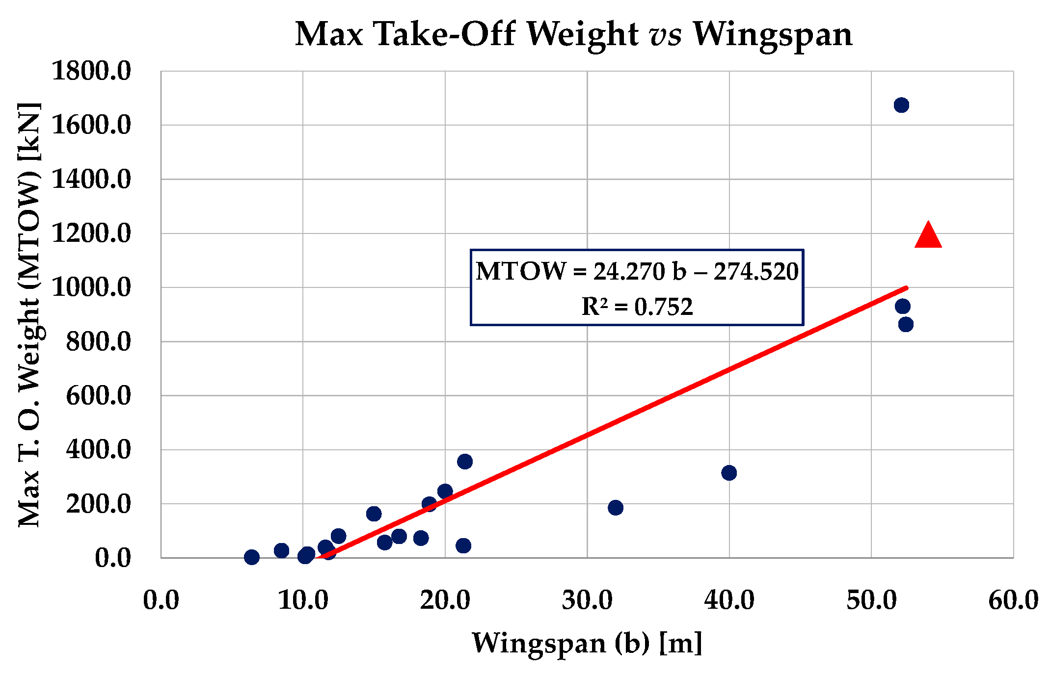
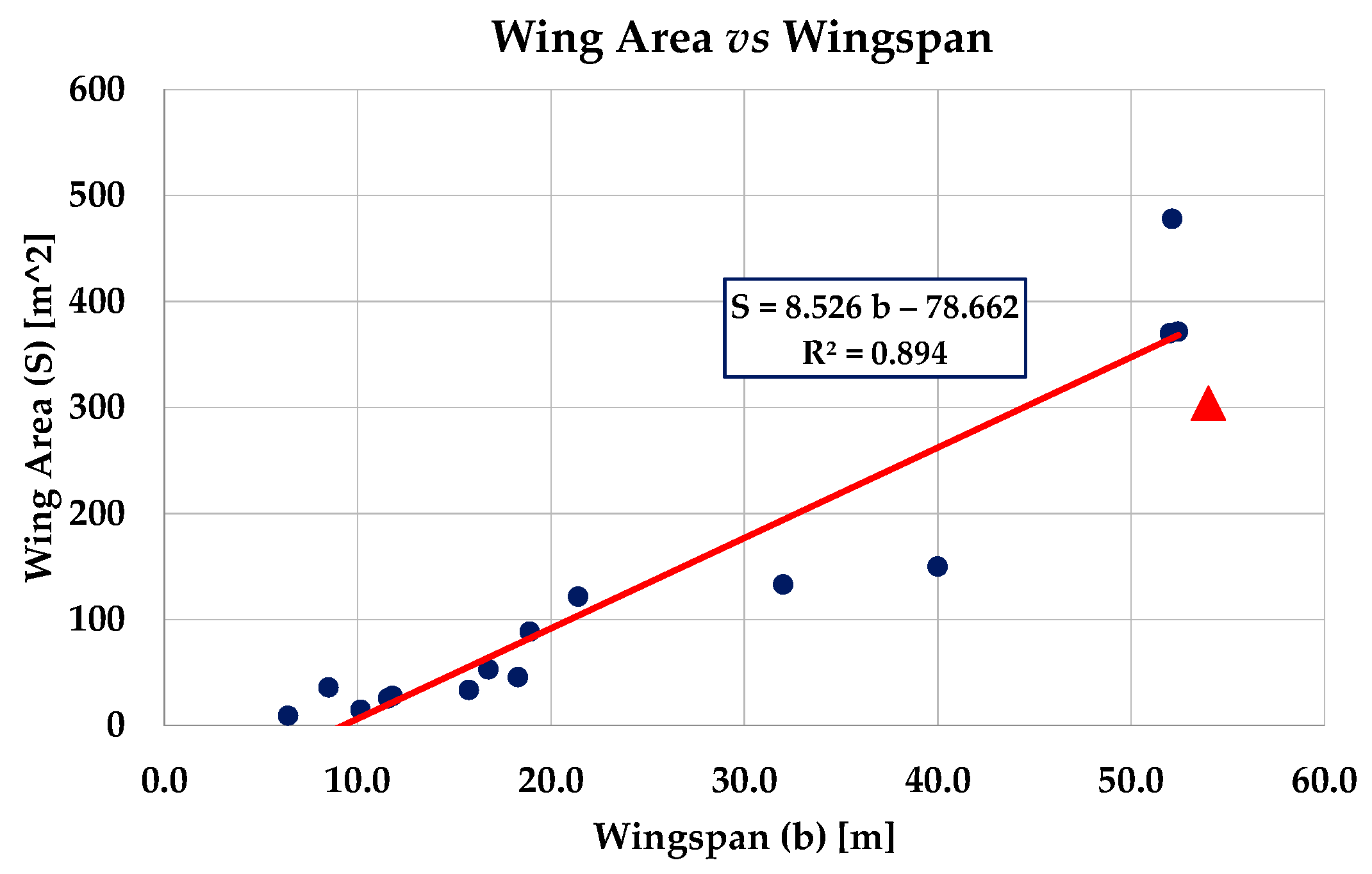
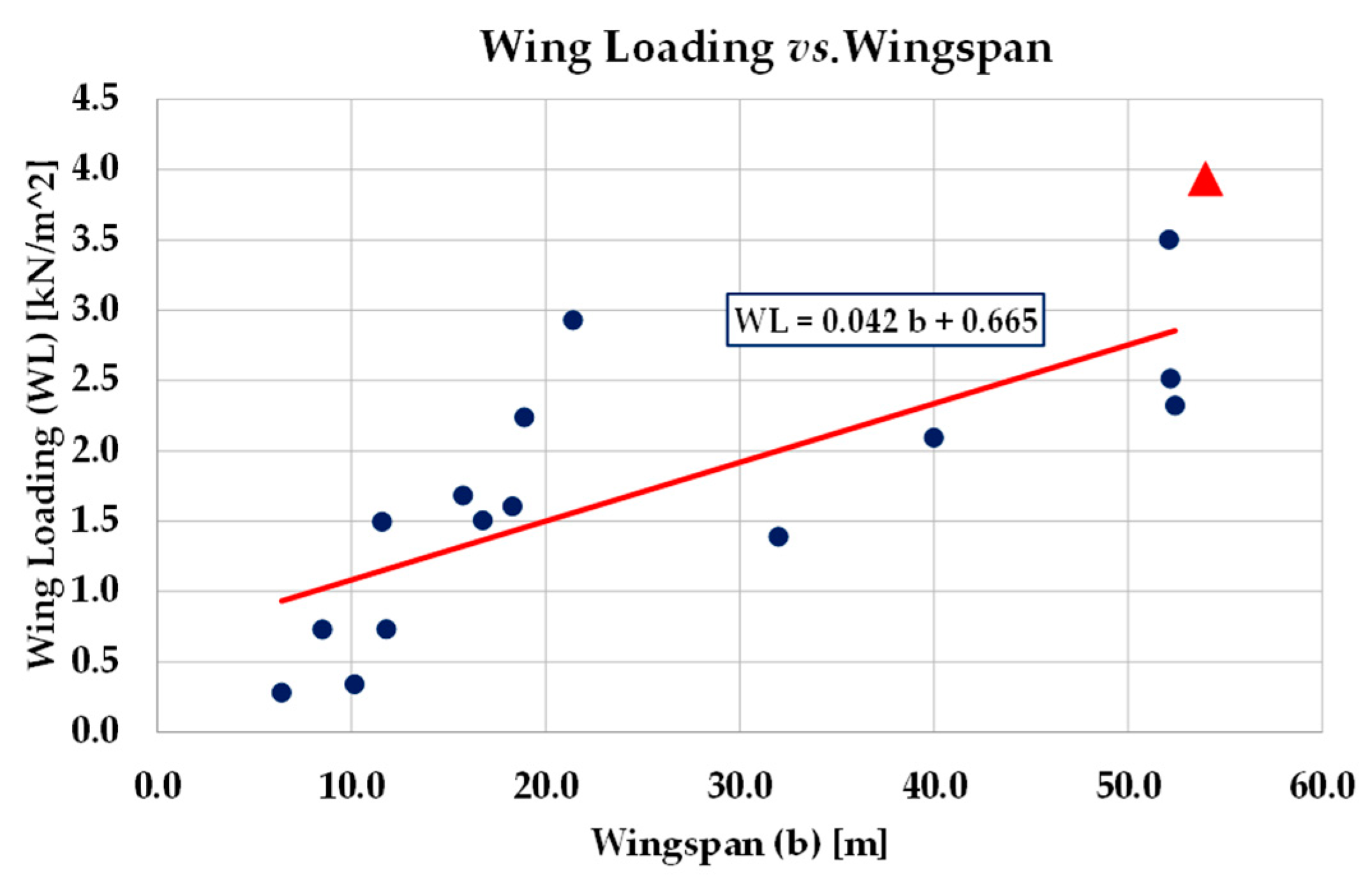
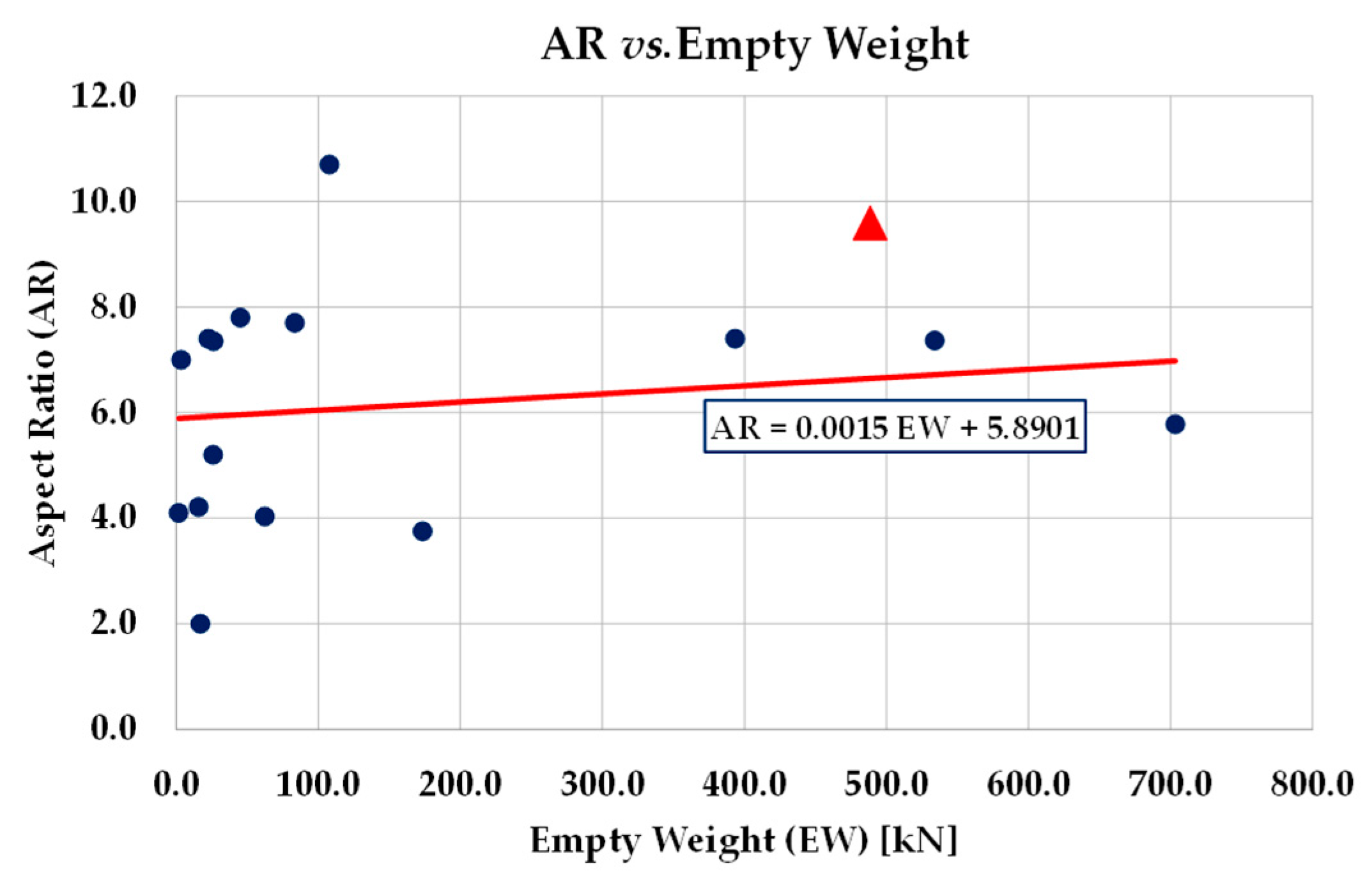
2.1. Historical Data Analysis

Table 1 shows a list of the examined flying wings with their relevant technical data. The data reported in Table 1 were collected by consulting several available sources [43,44,45,46,47,48,49,50]. The analysis of historical data provided a series of graphs that summarize the following relationships: empty weight vs. wingspan (Figure 1), maximum take-off weight (MTOW) vs. wingspan (Figure 2), wing area vs. wingspan (Figure 3), wing loading vs. wingspan (Figure 4), and aspect ratio (AR) vs. empty weight (Figure 5). The wing loading W/S data are calculated considering the maximum take-off weight condition. In the figures, we also reported the linear regression curves, and red-filled triangles indicate the configuration examined in this work, which was defined thanks to a trade-off study.
Even if flying wing configurations generally use airfoils with a reflected trailing edge, (as sketched in Figure 6), for flight stability reasons, (see as example [51]), we selected the Boeing BACXXX airfoil [52,53,54], which has a maximum thickness of 11.3% at 35% of the chord, and a maximum camber of 1.4% at 15% of the chord (Figure 7). Since, generally, the sign of the aerodynamic moment acting on an airfoil is negative (nose down effect), with a reflected trailing edge (Figure 6), the aerodynamic moment acting on the airfoil can change sign and become positive (nose up effect). This circumstance proves useful for designing a swept flying wing that is aero-mechanically stable.
Despite the specific characteristics of the reflected trailing edge airfoils, in this preliminary study, the choice to use a “traditional” airfoil was made with the aim of verifying that the stability of the wing could also be guaranteed with the use of control surfaces.

2.2. Comparison of Ground and Air Launch Systems: Velocity Budgets Estimation

The use of a flying wing as a carrier was motivated by a feasibility analysis based on the calculation and comparison of the velocity budgets, Δ v , necessary to place a satellite in low earth orbit (about 180–200 km); in this regard, Table 2 shows some reference data taken from [55]. The column Δ v t o t represents the velocities due to LEO orbital velocity added to the effects of gravity Δ v g r a v , atmospheric drag Δ v d r a g , and steering losses Δ v s t e e r . The column Δ v t o t indicates the velocity budgets without the effect of the rotation of the earth Δ v r o t , whose ta are reported in the last column of Table 2 for each launch system. The last column Δ v p r o p , which represents the propulsion velocity budget, is calculated by adding the total velocity budget and the velocity budget due to earth rotation, ( Δ v t o t + Δ v r o t ) , and also contains the ascent velocity Δ v s , that varies between 8.8 and 9.3 km/s [55]. The row Mean Values of Table 2 was added in this contest to estimate the velocities to be used in our conceptual analysis.
Table 3 shows the data estimated for the proposed flying wing carrier-launcher system assuming, as a starting point, the mean value of Δ v t o t = 9498   m / s (Table 2). Because the engine of the launcher ignites at an altitude of about h = 8.0   k m with an attitude angle θ = 45 ° , we assumed a reduction in the absolute values for gravity, drag, and steering losses of about the 20% of the mean values indicated in Table 2. Moreover, to be conservative, the assumed effect of earth rotation Δ v r o t = 100   m / s is set small enough to account for launches at higher latitudes.
A major advantage of using an atmospheric carrier is due to the initial velocity of the launcher when its engine ignites, i.e., Δ v c a r r i e r = 260   m / s . As expected, the final estimated ascent velocity for the flying wing launch system is lower than the references collected in Table 2 for ground launch systems; namely Δ v p r o p = 8802   m / s , with a reduction of about 320   m / s is obtained.
Starting from the estimated velocity changes Δ v p r o p = 9126   m / s for ground launch systems (Table 2) and Δ v p r o p = 8802   m / s for the flying wing (Table 3), we calculated the mass of propellant M p r o p needed to reach the low earth orbit assuming a specific impulse of I s p = 400   s and applying the well-known rocket equation of Tsiolkovsky (where g 0 is the standard gravity):
M p r o p = M 0 1 e Δ v p r o p / I s p g 0 ,
M 0 is the launcher mass. To obtain an estimation of the available payload mass, for both launch systems, we made, as an example, the assumptions summarized in Table 4.
Finally, the propellant mass and the payload masses for the two examined launch systems are summarized in Table 5.
The absolute value of the payload mass will depend on effective mass allocation, but whatever the mass allocation, when adopting the proposed air launch system, we would have savings of about 0.32   k m / s in the ascent Δ v , which would translate into at least 0.84% of the total launcher mass becoming available for the payload mass.

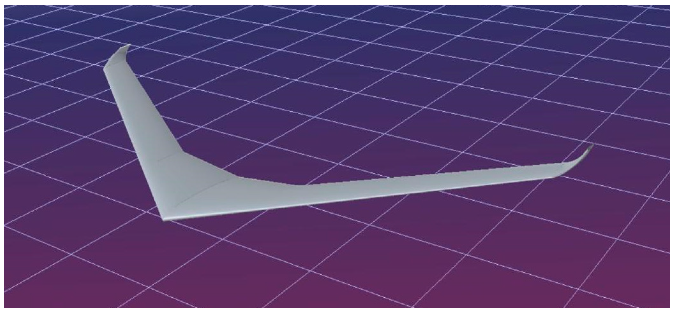
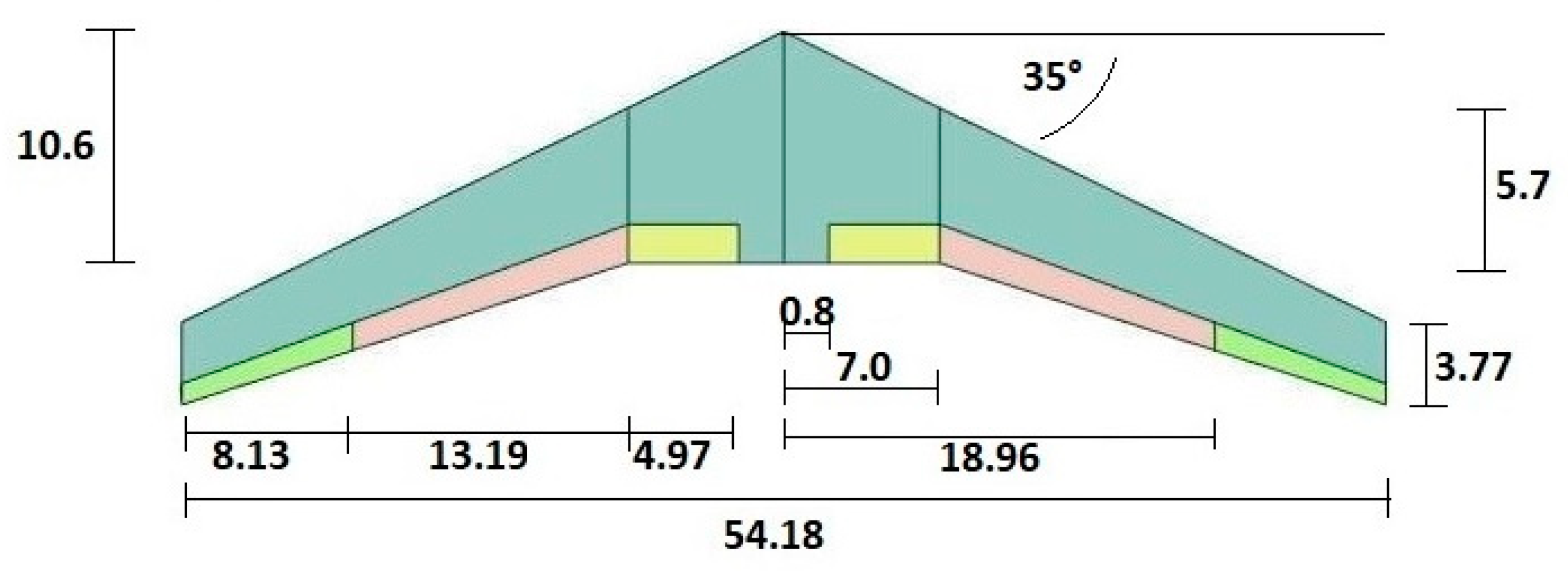
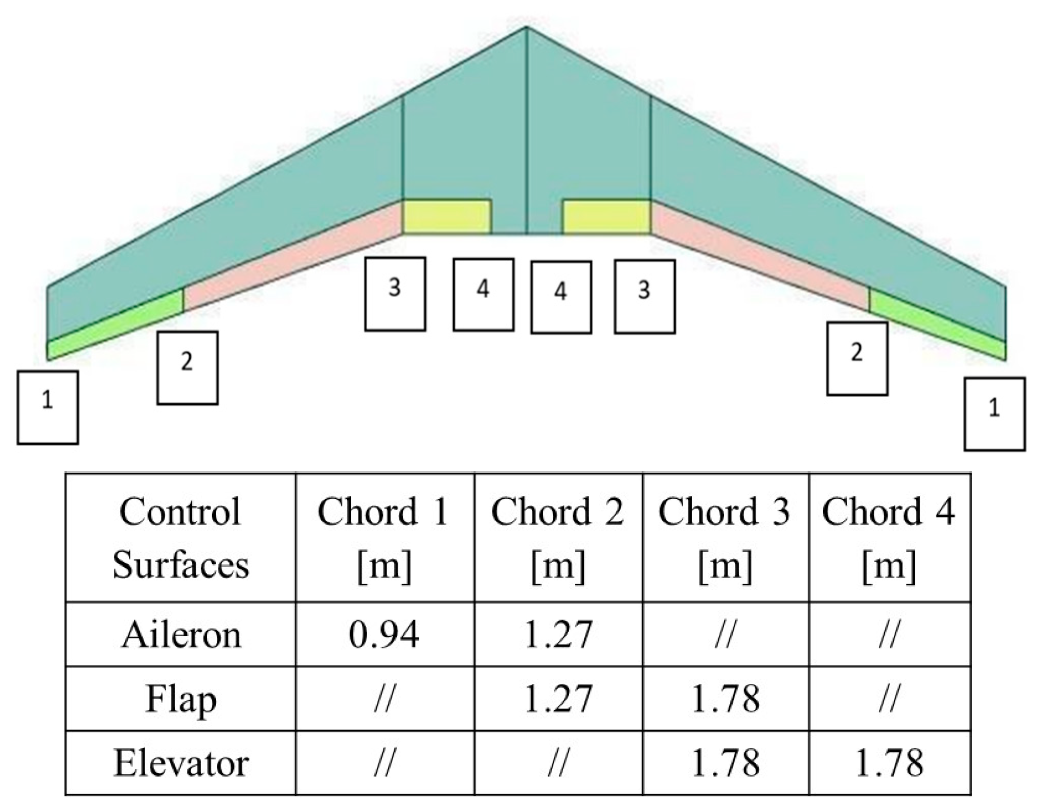
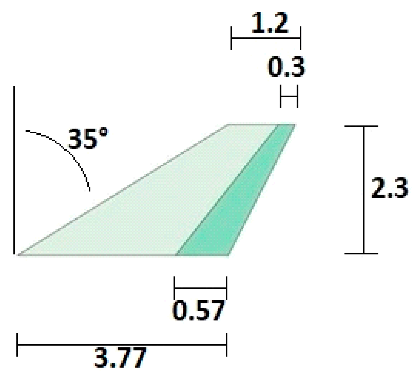
2.3. Description of Geometry and Mass Properties of the Carrier-Launcher System

Since our research is preliminary, and with the aim of verifying the effectiveness of the use of control surfaces for wing stabilization in each phase of a flight, the airfoil adopted in the present study does not have a reflected trailing edge; in fact, the selected airfoil is BACXXX, depicted in Figure 7 [54]. Table 6 reports the data of the configuration, and, in accordance with [26,27], the estimated mass and weight of the components of the carrier-launcher system. Thanks to a trade-off study, a wingspan of about 54.0 m has been selected to obtain increases in the lift-to-drag ratio without severe penalizations of the wing weight. We obtain an empty weight of 488.4 kN and a wing loading of 3,940 N/m2 for the complete configuration at take-off, considering a total mass of about 122,000 kg and a reference surface of about 304 m2. These values agree with historical data, as can be seen from the previous graphs (Figure 1, Figure 2, Figure 3, Figure 4 and Figure 5).
Winglets have been added at the tip of the wing to increase the lift-to-drag ratio. Figure 8 shows the CAD model of our conceptual flying wing configuration, and Figure 9 shows a plan sketch of the flying wing with its main dimensions, and with the selected layout of the control surfaces of the configuration [30].
The control surfaces consist of a pair of tip ailerons, a pair of centre double-acting flaps, and a pair of double-acting elevators; all the control devices are of single-surface type. The chord dimensions chords of the control surfaces are reported in Figure 10, whereas Figure 11 shows the dimensions of the winglet added to the flying wing tips with a cant angle of 35 degrees.

3. The Carrier-Launcher System Performance: Preliminary Analyses and Results

This section describes the analysis techniques and the results obtained in the research regarding the carrier-launcher system’s overall performance. This investigation is essentially conceptual in nature. Consequently, during the calculations, certain simplifications were applied, and, in certain instances, some data were predetermined to ensure that the outcomes were both conservative and coherent from an engineering standpoint.

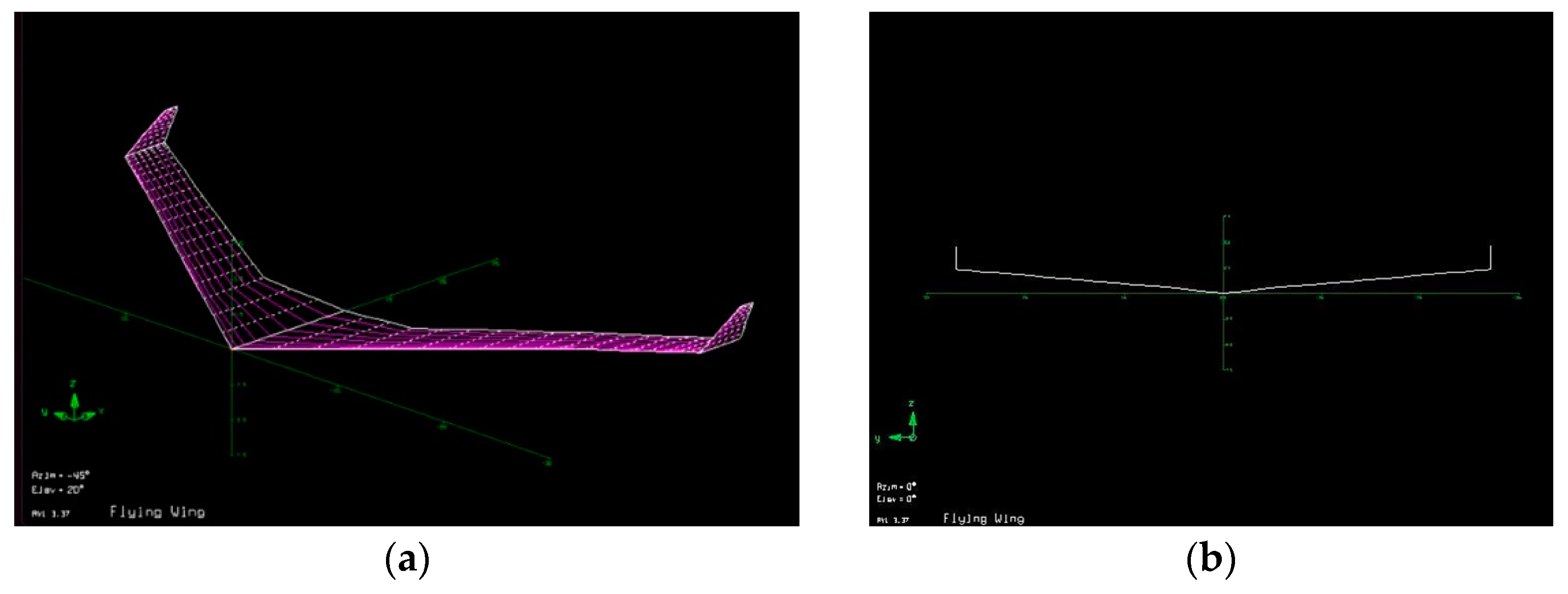
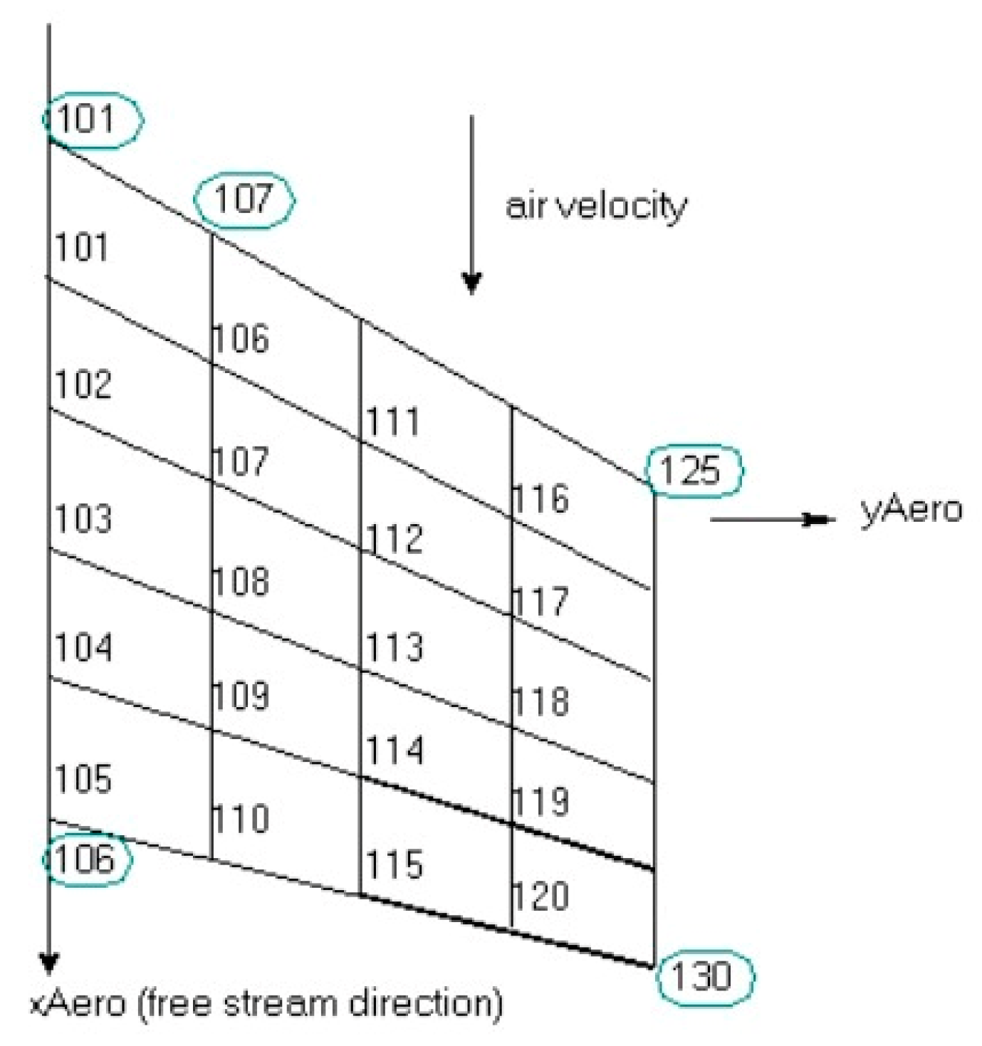
3.1. Aerodynamic and Aeromechanical Analyses of the Carrier-Launcher System

In the present conceptual study, the aerodynamic and aeromechanical performance (in terms of stability characteristics) of the flying wing carrier-launcher system were performed by means of the Athena Vortex Lattice (AVL) software [31]; this is a vortex-lattice solver, which adopts linearized potential aerodynamic theory, discretizing the lifting surfaces with panels. This code allows us to evaluate aerodynamic performance, stability characteristics, and trim conditions. The geometric data of the wing and the geometry of the airfoil (Figure 7) were properly modelled and introduced in AVL; Figure 12 shows a sketch of the model of the flying wing implemented in AVL.
For the flying wing carrier-launcher system, during the transfer flight, the cruise flight condition corresponds to an altitude h = 10,000   m (air density ρ = 0.41271   k g / m 3 ) with a cruise speed U = 239.60   m / s . The local sound speed is c = 299.5   m / s and the cruise Mach number is M = 0.8 (ISO standard). Referring to the MTOW in a conservative way when considering cruising, the estimated lift C L _ c r u i s e coefficient in a cruise flight is
C L _ c r u i s e = 2   M T O W / ρ S U 2 = 0.33 ,
and the drag coefficient is shown by
C D _ c r u i s e = C D 0 _ c a r r i e r l a u n c h e r + C L _ c r u i s e 2 / π   A R   e ,
where the value of the Oswald coefficient, e = 0.9075 , has been estimated by applying the model described in [28]. The drag coefficient at zero lift has been calculated starting from the analysis performed with the use of AVL; thus, for the flying wing, C D 0 _ c a r r i e r = 0.013 . To take into account the effect of the launcher, we assumed a 20% increase in the carrier-launcher zero-lift drag coefficient (a pure translation in the polar curve).
C D 0 _ c a r r i e r l a u n c h e r = 1.20 × 0.013 = 0.0156 .
Moreover, for a stable and trimmed flight condition (i.e., pitching moment equal to zero), we must rotate upward the central flap surfaces of an angle of approximately δ = 21.08   d e g ; in the equilibrium condition, the trim angle of attack is α w = 5.75   d e g . This latter control maneuver produces, due to the induced drag, an increase in the drag coefficient of about C D _ c r u i s e _ i n d = 0.0156 , as estimated by AVL code, so we may assume the finale value of the cruise drag coefficient as (adding up all the terms):
C D _ c r u i s e = C D 0 _ c a r r i e r l a u n c h e r + C D _ c r u i s e _ i n d = 0.0156 + 0.0156 = 0.0312 .
In a cruise flight condition, the estimated lift-to-drag ratio (or lift-to-drag ratio L/D) of the system is
L / D = C L _ c r u i s e / C D _ c r u i s e = 0.33 / 0.0312 = 10.58 .
As mentioned above, with the code AVL, it is possible to perform preliminary aeromechanical analyses and stability assessments; specifically, the cruise static stability margin (SM), i.e., the distance between the centre of gravity of the system and the neutral point divided by the mean aerodynamic chord (MAC), can be estimated in different flight conditions. AVL is indeed able to calculate the longitudinal position of the aircraft neutral point; then, by inserting the mass distribution of the model and the related longitudinal position of the centre of gravity, the SM is computed (Figure 13).
The MAC of the considered flying wing is equal to 7.73 m. Assuming the origin of the longitudinal x coordinates at the vertex of the wing’s leading edge (nose of the wing), the stability margin is computed by means of Equation (7):
S M c r u i s e = x n p x c g / M A C = 9.60 7.64 / 7.73 = 0.25 ,
where x n p , x a c , w and x c g are the longitudinal coordinates of the neutral point, aerodynamic centre of the wing, and centre of gravity of the carrier-launcher system, respectively. It has been assumed that the longitudinal position of the neutral point is equal to the longitudinal position of the aerodynamic centre; all the data are reported in Table 7.
The estimated stability margin after the release manoeuvre of the launcher, assuming a reduced fuel mass of about 37,300 kg, is
S M n o l a u n c h e r = x n p x c g / M A C = 9.60 8.02 / 7.73 = 0.20 .
In both examined conditions, the stability margin is positive and reaches typical values of a transport aircraft. The system is statically stable from an aeromechanical point of view if, in a generic equilibrium condition, and assuming the centre of gravity as the pole of moments, the overall moment is zero and the aerodynamic moment at zero lift is sufficiently large and positive. Neglecting higher order infinitesimal terms and including the effect of the thrust, we have for the overall moment coefficient (Figure 14):
C M c g , s y s t e m = C M a c , s y s t e m + C L , s y s t e m · h h n C T · z e z = 0
where h = x c g / M A C and h n = h a c , w = x n p / M A C are, respectively, the dimensionless coordinates of the centre of gravity and of the aerodynamic centre of the carrier-launcher system. C T is the thrust coefficient; z and ze denote two dimensionless quantities, such that, indicating with c = MAC the reference chord, z c is the vertical distance between the c.g. and the reference plane of the wing, and z e c is distance between the thrust axis and the reference plane of the wing (Figure 14). The quantities z c and z e c are positive in the upper half plane.
For the system to be stable,
C M a c , s y s t e m C T · z e z > 0
and C L , s y s t e m = C L α , s y s t e m · α w ,
C M c g , s y s t e m / α w = C L α , s y s t e m · h h n < 0 ,
where α w is the angle of attack and C L α , s y s t e m is the slope of the lift curve.
The requirement of Equation (10) can be critical for a flying wing; this is the reason why it is almost obligatory to use profiles with a reflected trailing edge (Figure 6). Anyway, to ensure stability in the various phases of the flight, the aerodynamic control surfaces (Figure 10) can be used in an appropriate and combined manner.

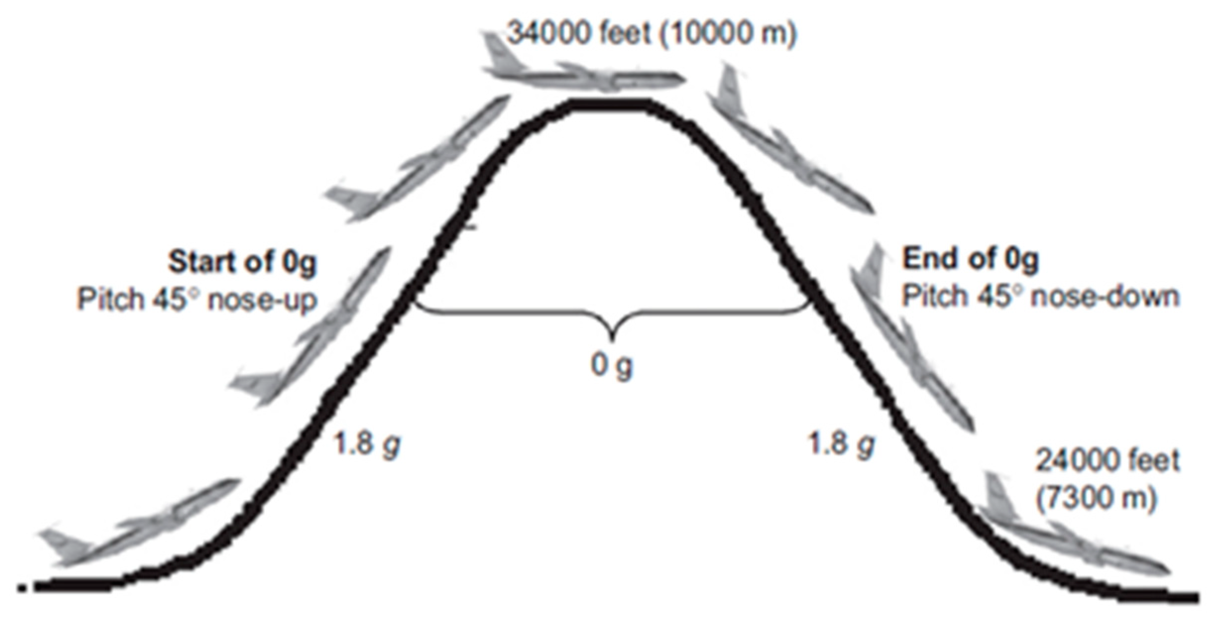
3.2. Choice of Engines Needed to Perform the Parabolic Manoeuvre

The engines adopted in the preliminary configuration are four Rolls-Royce UltraFan engines [56]. These engines satisfy the requirements in terms of thrust to perform the first phase of the launcher release manoeuvre. In the present case, from an altitude of about 6000 m, with a speed of 260 m/s, and M = 0.822, the launcher should perform a pull-up manoeuvre. It should climb to an angle γ = 45 ° and up to an altitude of about 8000 m to release the launcher at the beginning of the parabolic flight phase. Figure 15 shows a typical trajectory flown during a parabolic flight [10].
During the 1.8 g phase of flight (pull-up manoeuvre), the lift ( L ) is
L = 1 / 2 ρ S V 2 C L _ c l i m b = 1.8 W r e d ,
and the requested thrust T r e q is calculated, considering no acceleration along the climbing trajectory, by
T r e q = D + W r e d s e n γ = 1 / 2 ρ S V 2 C D _ c l i m b + W r e d s e n γ ,
where ρ is the air density, S the reference surface of the wing, V = 260   m / s the velocity, D the aerodynamic drag, W r e d the reduced weight of the carrier configuration at the beginning of the pull-up maneuver, γ is the trajectory angle (the velocity vector and thrust axis are aligned with the trajectory), and C L _ c l i m b and C D _ c l i m b are the aerodynamic coefficients of lift and drag of the carrier-launcher configuration, respectively. To evaluate W r e d at the beginning of the manoeuvre, we assume that the mass of the remaining fuel is 60% of its initial mass; therefore, the mass of fuel is 37,300   k g and the actual reduced weight of the carrier-launcher configuration with four engines is W r e d = 952,590   N .
In this preliminary analysis, to obtain coherent results, we assume that the carrier starts the manoeuvre depicted in Figure 15 [10] at an altitude of h = 6000   m , and while the carrier is climbing, it can safely reach a maximum altitude of about h = 8000   m (as a reference, the final value of the trajectory radius is R = 6300   m ). Therefore, to perform a preliminary verification of the thrust requirements, we refer to the altitude h = 8000   m : in this case, the air density is ρ = 0.52517   k g / m 3 and from Equation (12) we estimate a value of the lift coefficient C L _ c l i m b = 0.32 (very similar to the lift coefficient in cruise condition). The same result was obtained with the use of the AVL software, as previously mentioned.
Equation (13) allows us to estimate the maximum required thrust to execute the manoeuvre. Again, from AVL calculation C D 0 _ c a r r i e r = 0.013 , and, as performed for the cruise condition, we increase this value by 20% to account for the launcher during the climbing phase of the parabolic manoeuvre, thus C D 0 _ c l i m b = 0.0156 .
In this case, for a stable flight condition, we must rotate the central flap surfaces (upward direction) of an angle of approximately δ = 19.84   d e g , and, in the equilibrium condition, the angle of attack is α w = 5.24   d e g . These results were obtained with AVL setting the pitching moment equal to zero.
The induced drag produces an increase in the drag coefficient of about (AVL result) C D _ c l i m b _ i n d = 0.0145 , thus the final value of the manoeuvre drag coefficient is
C D _ c l i m b = C D 0 _ c l i m b + C D _ c l i m b _ i n d = 0.0156 + 0.0145 = 0.0301 .
Inserting this value in Equation (13) we obtain
T r e q = 1 / 2 × 0.52517 × 304.36 × 260 2 × 0.0301 + 952,590 × 0.707 / 1000 = 836.4   k N
and we must compare this value with the available thrust.
The PW4000-112 engine [41], considered as a candidate engine in first instance, develops a maximum thrust at a sea level of about 98,000   pounds , i.e., 435.9   k N . To consider, in a first approximation, the effect of altitude at h = 8000   m , we may use the relationship based on density ratio:
T m a x P W e n g i n e = T 0 ρ / ρ 0 = 435.9   k N × 0.52517 / 1.225 = 435.9   k N × 0.4287 = 186.9   k N ,
thus, estimating a reduction of the maximum thrust of about 57%. As a result, the maximum thrust of four PW4000-112 engines is not sufficient to perform the required manoeuvre.
The Rolls-Royce UltraFan engine [56] develops a maximum thrust at sea level of about 110,000   pounds , i.e., 489.3   kN . For this engine, we obtain
T m a x R R e n g i n e = T 0 ρ / ρ 0 = 489.3   k N × 0.52517 / 1.225 = 489.3   k N × 0.4287 = 209.8   k N .
Finally, with four Rolls-Royce UltraFan engines we have
4   T m a x R R e n g i n e = T m a x c a r r i e r = 4 × 209.8 = 839.1   k N > T r e q ,
and the thrust requirement is satisfied, although with almost zero margin.
For the proposed carrier-launcher system, the altitude h = 8000   m represents the maximum flight level at which the parabolic flight phase begins, when the thrust begins to be reduced. These preliminary calculations demonstrate that to practically accomplish this type of mission, four high-thrust engines must be installed on the flying wing carrier-launcher system.

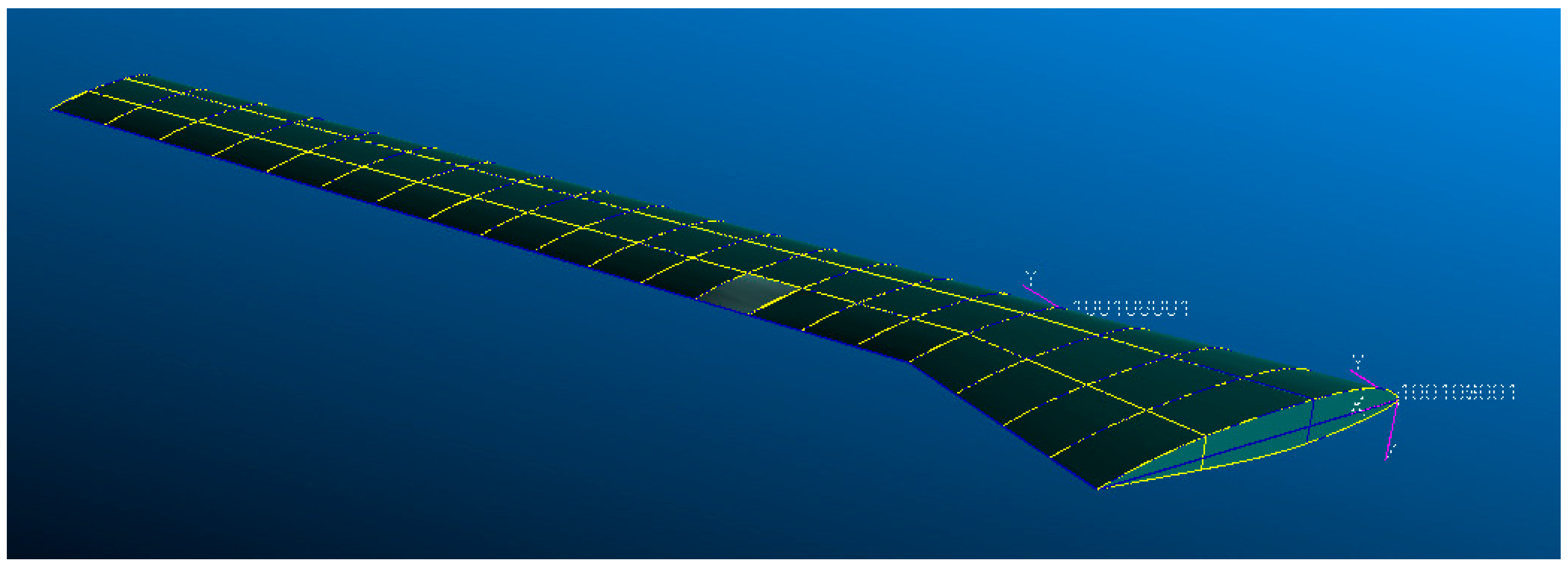
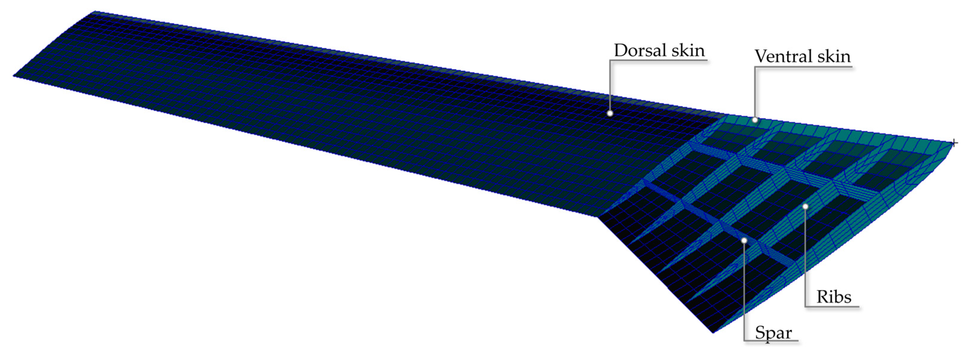
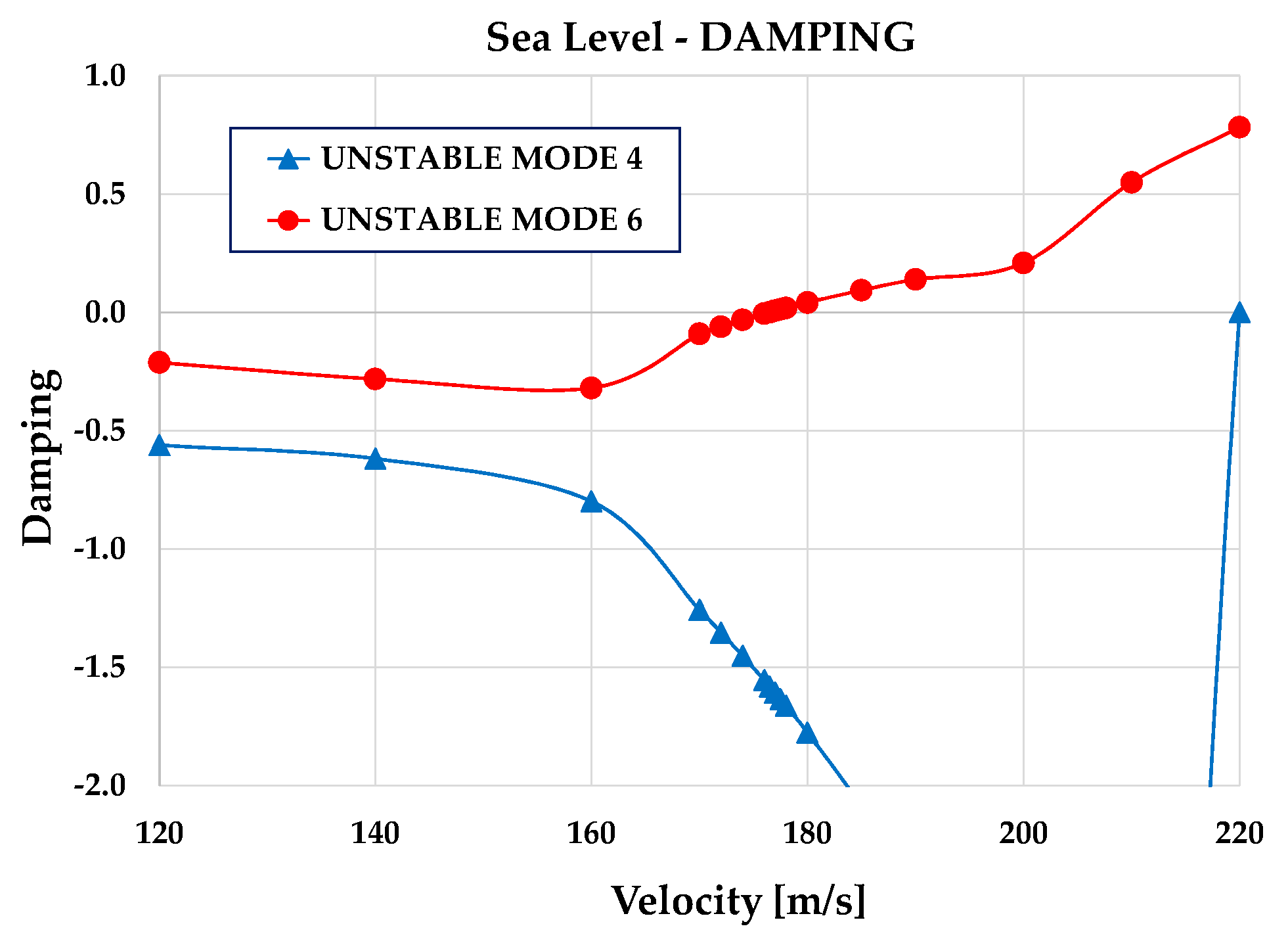
3.3. Modal Analyses and Aeroelastic Analyses of the Carrier-Launcher System

As a major issue in the development of such lifting architectures is related to aeroelastic problems, because of the initial sizing processes, the last part of the research involved a preliminary study of the aeroelastic behaviour of the flying wing. To conduct this study, the finite element software MSC NASTRAN was used [57]. In this conceptual design phase, a half-wing model was studied. A two-spar wing-box structure was modelled, making standard assumptions in terms of sizing of the various components, and an aluminium alloy was selected as the structural material [30]. Both ribs and spars (Table 8) are tapered, and they were modelled with shell elements.
The landing gears have been modelled as concentrated masses positioned in the correct stations, while the launcher and the two engines are connected to the structure with the RBE2 connection of NASTRAN; the launcher is placed in the root section (half of its inertia characteristics have been introduced). Table 9 and Table 10 contain the data used to prepare the finite element model.
The structural mesh of the wing-box is composed of 4165 nodes and about 4446 CQUAD4 elements. Figure 16 and Figure 17 show, respectively, a sketch of the geometry of the half-wing model and a sketch of the structural mesh implemented in PATRAN [58]. In NASTRAN (Fight Loads tool), the aerodynamic surface covers the entire plan form of the wing and is connected (through surface splines) to the displacements of the structural nodes of the wing-box upper skin.
As for as the aerogrid, it is built by fragmenting the surfaces into panels; each panel is numbered and perfectly defined. We built two aerogrids: one for the inboard surface and one for the outboard surface in a sequential way along the span. Figure 18 shows an example of the aerodynamic mesh which can be implemented to carry out the aeroelastic analyses with the software NASTRAN [57]. In this case, we used five subdivisions in the wing chord direction and a total of ten subdivisions in the wingspan direction.
Two types of modal analysis were performed: the first with the root section free to move in the vertical plane (in this case only the longitudinal translation is constrained for all the nodes of the root section), and the second with the root section clamped. In the first case (free wing), for all the nodes of the root section, the degrees of freedom “1345” are set equal to zero (the two translations in the chord direction UX and in the wingspan direction UZ, and the two rotations around the chord direction ROTX—rolling—and the in-plane rotation ROTY—yaw). Vertical translation (UY) and pitching degrees of freedom (ROTZ) are free. In the second case (clamped wing), all nodes at the root section have been fixed; therefore, all degrees of freedom “123456” are set to zero (in a Global Reference Frame).
Table 11 shows the list and the comparison of first natural frequencies calculated with the mentioned modal analyses of the free half-wing and clamped half-wing, respectively.
Table 12 contains a comparison of natural modes of vibration in terms of their qualitative shape. As is known, due to the different constraint conditions, the free-wing model has slightly higher frequency values.
The aeroelastic analyses were performed at sea level and in cruise flight condition. In these calculations, we assumed h = 11,000   m as cruising altitude. To obtain preliminary results, the half-wing clamped model was considered (neglecting rigid modes effect). We selected the p-k method [57] to extract the complex eigenvalues (10 complex roots). A structural damping of 0.02 was assumed. In both conditions, we inserted in the input file of NASTRAN a suitable list of speeds to be analysed in order to identify the sign variation of the overall damping parameter, and therefore the instability conditions. It is known that with the p-k method it is also possible to identify the conditions of static divergence; in this case, the imaginary part of the eigenvalue, which is related to the frequency of the unstable mode, tends to zero. In fact, this happened in one of the flight conditions examined.
For the flight condition at sea level, we found a flutter instability in the range 170 ÷ 180   m / s corresponding to a flutter speed of about 176.5   m / s with a Mach number of M = 0.52 and frequency of 1.4   H z . A second form of instability instead highlighted a condition of divergence with a critical speed equal to about 220   m / s ( M = 0.64 ). In the cruise flight condition, we found flutter instabilities. The first instability occurred at a speed of about 281.5   m / s (Mach number M = 0.954 ) with a frequency of about 1.9   H z ; other forms of instability occurred for unrealistic Mach number values. The forms of instabilities found are listed in Table 13. Damping and frequency, as a function of flight speed, are shown in Figure 19 and Figure 20 for the sea level condition. The data calculated for the cruise flight condition are shown in Figure 21 and Figure 22.
Thanks to the PATRAN animation tool, it was observed that for the sea level condition, Mode 4 is a bending mode while Mode 6 is a bending-torsion mode. In a cruise flight condition, Mode 6 appears as a pure bending mode, whereas another high-speed mode highlighted a combination of bending and torsion. In these cases, it should be noted that the term mode and its order number are related to the complex eigenvector list calculated by NASTRAN with the available aeroelastic solver, and therefore are not to be confused with natural modes of vibration.
In the cruise condition, divergence was found in the supersonic regime, but this result was also considered unreliable. Figure 23 shows, as an example, the sketch of the unstable Mode 6 (the flutter mode) calculated for the half-wing clamped model at the sea level flight condition (figure shows only the wing-box structure deflections).

4. Discussion

A system for deploying small satellites in LEO, in a range of 100–500 kg, has been proposed and studied at a conceptual level. The flying system is unmanned and remotely controlled; it is composed of a flying wing and a small launcher. The CAD visualization of the carrier-launcher system discussed in this paper is shown in Figure 24. The research proposed here has the aim of representing the first step in the development of a novel air launch system to be a candidate for a more effective and efficient solution, with respect to the current technical solutions. To do so, the first action needed is a conceptual feasibility study, focused on conceptual design and preliminary performance assessment of the concept.
The main feature that distinguishes this air launch system from others existing in the technical literature [59] consists in the method by which the separation of the launcher from the carrier takes place. The separation between the two components of the system occurs during the execution of a parabolic manoeuvre that allows the internal forces, due to the gravitational effect, to be reduced to a minimum, thus simplifying the mechanical procedure for detaching the launcher. It has therefore been thought and verified that the launcher is released and ignites its own thruster, with a high speed and at an altitude of about 8000 m, at the end of a pull-up manoeuvre of the wing which performs a parabolic manoeuvre.
A conceptual configuration has been defined at the end of a state-of-the-art study. The aerodynamic performance, the basic characteristics of the flight mechanics, and the aeroelastic behaviour have been preliminarily studied thanks to the use of well-known software (AVL [31] and NASTRAN [57]). The maximum take-off weight of the system, which can cover a long cruise range (about 8000 km) up to the actual launch area, is about 1200 kN. The weight is therefore much lower than that of other conventional configurations of air launch systems [42].
As is well known, the stability of the flying wing can be a critical issue. In this work, it is demonstrated, at least preliminarily, that even in the most critical flight phase (parabolic flight) aeromechanical stability can be ensured using conventional control surfaces, without a strong reduction in lift-to-drag ratio.
The safe execution of the parabolic manoeuvre requires the use of four high-thrust latest generation jet engines [56]. First-level analyses have shown that the system does not present evident criticalities due to forms of aeroelastic instability. However, further analyses are necessary to consider the effect of the launcher in a more realistic way, both from an aerodynamic and an inertial point of view. A non-secondary topic that certainly falls within the future developments of this research concerns the use of more reliable aerodynamic calculation systems (CFD methodologies) for a more in-depth study of the aerodynamic performance of the configuration, both at low speed (with a high angle of attack) and in transonic flight conditions. Another technical topic to be explored concerns the design of the system for connecting the launcher to the carrier. Among the technical requirements that this system will have to guarantee, the reliability and simplicity of execution of the separation phase of the launcher must certainly be considered.

5. Conclusions

This study presented a conceptual design of a flying wing carrier-launcher for satellites in low earth orbit. The concept represents a breakthrough solution in the field of LEO satellite launch systems, providing a more flexible and effective platform to accomplish this type of mission. The primary objective of this investigation was to assess the feasibility of the proposed system as a potential solution for satellite launches. Indeed, the main aim of this conceptual research is to characterize a novel and innovative system that offers a more efficient, effective, low-cost, and flexible solution compared to existing ground launcher technologies, providing its main features in the very early design stage. The proposed flying wing carrier-launcher is designed to address the limitations and challenges of conventional launcher systems by leveraging on the concept of “re-use” of the launcher platform. The introduction of such a system could potentially reform the sector of satellite launches and provide a more efficient means of accessing space.
The study involved conceptual sizing to evaluate the flying wing carrier key performance and possible issues; the results indicate that the proposed design may represent a promising starting point to initialize a further detailed engineering process on the development of such a carrier-launcher system. The investigation has been conducted by assessing the initial sizing of the flying wing, in terms of aerodynamics, thrusts, weights, and structural behaviour. The sizing process has taken the selected air launch operation into account, namely a release at a zero g parabolic manoeuvre.
In this path, further research and development are necessary to refine and improve the fidelity of the proposed analyses, and to technically develop the proposed concept. Critical issues that require further investigation include the optimization of the geometry, mass distribution, propulsion system, and control systems; furthermore, the design should be subjected to more detailed aerodynamic and structural analyses to assess its overall performance more reliably. Indeed, to improve the fidelity of this study, future research could focus on conducting more detailed multidisciplinary simulations and systems analyses, based on higher fidelity tools, such as CFD analyses for aerodynamic evaluations, or FEM-based structural design and optimization.
The proposed system allows saving the weight of the carrier (since there is neither a fuselage nor a tail), and therefore produces an increase in the efficiency of the launch system as a whole. Nevertheless, this study serves as an initial milestone for future research aiming to stimulate and inspire further development for the proposed concept.

Author Contributions

Conceptualization, M.R.C.; methodology, M.R.C. and F.B.B.; software, V.C. and V.B.; validation, M.R.C., V.C. and V.B.; formal analysis, F.B.B.; investigation, M.R.C. and F.B.B.; resources, V.C. and V.B.; data curation, F.B.B.; writing—original draft preparation, M.R.C. and F.B.B.; writing—review and editing, K.A.S. and G.P. All authors have read and agreed to the published version of the manuscript.

Funding

This research received no external funding.

Institutional Review Board Statement

Not applicable.

Informed Consent Statement

Not applicable.

Data Availability Statement

The data presented in this study are contained within the paper.

Conflicts of Interest

The authors declare no conflict of interest.

References

  1. Sippel, M.; Stappert, S.; Koch, A. Assessment of multiple mission reusable launch vehicles. J. Space Saf. Eng. 2019, 6, 165–180. [Google Scholar] [CrossRef] [Green Version]
  2. Dresia, K.; Jentzsch, S.; Waxenegger-Wilfing, G.; Hahn, R.D.S.; Deeken, J.; Oschwald, M.; Mota, F. Multidisciplinary Design Optimization of Reusable Launch Vehicles for Different Propellants and Objectives. J. Spacecr. Rocket. 2021, 58, 1017–1029. [Google Scholar] [CrossRef]
  3. Brevault, L.; Balesdent, M.; Hebbal, A. Multi-Objective Multidisciplinary Design Optimization Approach for Partially Reusable Launch Vehicle Design. J. Spacecr. Rocket. 2020, 57, 373–390. [Google Scholar] [CrossRef]
  4. Ansgar, M.; Josef, K.; Johannes, R.; Daniel, K.; Sebastian, K.; Davide, B.; Vos, J.; Matthew, J.; Anett, K.; João, C. Retro propulsion assisted landing technologies (retalt): Current Status and Outlook of the EU Funded Project on Reusable Launch Vehicles. In Proceedings of the 70th International Astronautical Congress, Washington DC, USA, 21–25 October 2019; Available online: https://elib.dlr.de/132566/ (accessed on 1 April 2023).
  5. Cheng, G.; Jing, W.; Gao, C. Recovery trajectory planning for the reusable launch vehicle. Aerosp. Sci. Technol. 2021, 117, 106965. [Google Scholar] [CrossRef]
  6. Burton, R.L.; Brown, K.; Jacobi, A. Low-Cost Launch of Payloads to Low Earth Orbit. J. Spacecr. Rocket. 2006, 43, 696–698. [Google Scholar] [CrossRef]
  7. Crisp, N.; Roberts, P.; Livadiotti, S.; Oiko, V.; Edmondson, S.; Haigh, S.; Huyton, C.; Sinpetru, L.; Smith, K.; Worrall, S.; et al. The benefits of very low earth orbit for earth observation missions. Prog. Aerosp. Sci. 2020, 117, 100619. [Google Scholar] [CrossRef]
  8. del Portillo, I.; Cameron, B.G.; Crawley, E.F. A technical comparison of three low earth orbit satellite constellation systems to provide global broadband. Acta Astronaut. 2019, 159, 123–135. [Google Scholar] [CrossRef]
  9. Curzi, G.; Modenini, D.; Tortora, P. Large Constellations of Small Satellites: A Survey of Near Future Challenges and Missions. Aerospace 2020, 7, 133. [Google Scholar] [CrossRef]
  10. Karmali, F.; Shelhamer, M. The dynamics of parabolic flight: Flight characteristics and passenger percepts. Acta Astronaut. 2008, 63, 594–602. [Google Scholar] [CrossRef] [Green Version]
  11. Pletser, V. Aircraft Parabolic Flights: A Gateway to Orbital Microgravity and Extra-Terrestrial Planetary Gravities. 2020. Available online: https://www.intechopen.com/chapters/72224 (accessed on 29 May 2020).
  12. Goetzendorf-Grabowski, T. Flight dynamics of unconventional configurations. Prog. Aerosp. Sci. 2023, 137, 100885. [Google Scholar] [CrossRef]
  13. Wang, Y.; Liu, L.; Xing, Y.; Yang, Z. Investigation of wing structure layout of aerospace plane based on the finite element method. Adv. Mech. Eng. 2017, 9, 1687814017713701. [Google Scholar] [CrossRef] [Green Version]
  14. Pan, Y.; Huang, J. Influences of airfoil profile on lateral-directional stability of aircraft with flying wing layout. Aircr. Eng. Aerosp. Technol. 2019, 91, 1011–1017. [Google Scholar] [CrossRef]
  15. Keidel, D.; Molinari, G.; Ermanni, P. Aero-structural optimization and analysis of a camber-morphing flying wing: Structural and wind tunnel testing. J. Intell. Mater. Syst. Struct. 2019, 30, 908–923. [Google Scholar] [CrossRef]
  16. Sarigul-Klijn, M.; Sarigul-Klijn, N.; Hudson, G.; McKinney, B.; Voss, J.; Chapman, P.; Morgan, B.; Tighe, J.; Kramb, J.; Doyle, K. Selection of a Carrier Aircraft and a Launch Method for Air Launching Space Vehicles. In Proceedings of the AIAA SPACE 2008 Conference & Exposition, San Diego, CA, USA, 9–11 September 2008. [Google Scholar] [CrossRef] [Green Version]
  17. Sarigul-Klijn, M.; Sarigul-Klijn, N.; Morgan, B.; Tighe, J.; Leon, A.; Hudson, G.; McKinney, B.; Gump, D. Flight Testing of a New Earth-to-Orbit Air Launch Method. J. Aircr. 2006, 43, 577–583. [Google Scholar] [CrossRef]
  18. Sarigul-Klijn, N.; Sarigul-Klijn, M.; Noel, C. Air Launching Earth-to-Orbit Vehicles: Delta V gains from Launch Conditions and Vehicle Aerodynamics. In Proceedings of the 42nd AIAA Aerospace Sciences Meeting and Exhibit, Reno, NV, USA, 5–8 January 2004. [Google Scholar] [CrossRef]
  19. Sarigul-Klijn, N.; Sarigul-Klijn, M.; Noel, C. Air-Launching Earth to Orbit: Effects of Launch Conditions and Vehicle Aerodynamics. J. Spacecr. Rocket. 2005, 42, 569–575. [Google Scholar] [CrossRef]
  20. Dagur, R.; Singh, V.; Grover, S.; Sethi, N.; Arora, B.B. Design of Flying Wing UAV and Effect of Winglets on its Performance. Int. J. Emer. Tech. Adv. Eng. 2018, 8, 414–428. [Google Scholar]
  21. Rajendran, S. Design of Parametric Winglets and Wing Tip Devices—A Conceptual Design Approach. Master’s Thesis, Linkoping University, Institute of Technology, Linkoping, Sweden, 2012. Available online: https://liu.diva-portal.org/smash/get/diva2:547954/FULLTEXT01.pdf (accessed on 1 April 2023).
  22. Anderson, J.D., Jr. Introduction to Flight, 7th ed.; McGraw-Hill Education: New York, NY, USA, 2011. [Google Scholar]
  23. Kundu, A.K. Aircraft Design; Cambridge University Press: Cambridge, UK, 2010. [Google Scholar]
  24. Hoerner, F.S. Fluid-Dynamic Drag; Hoerner Fluid Dynamics: Bakersfield, CA, USA, 1992. [Google Scholar]
  25. Tulapurkara, E.G. Flight Dynamics–II (Stability and Control), Department of Aerospace Engineering, I.I.T. Madras, Chennai-600036, India. 2008. Available online: https://cnj.atu.edu.iq/wp-content/uploads/2020/03/3b.pdf (accessed on 1 April 2023).
  26. Raymer, D.P. Aircraft Design: A Conceptual Approach, 6th ed.; AIAA: Reston, VA, USA, 2018. [Google Scholar]
  27. Lan, C.E.; Roskam, J. Airplane Aerodynamics and Performance, 5th ed.; DARcorporation: Lawrence, KS, USA, 2016. [Google Scholar]
  28. Niţă, M.; Scholz, D. Estimating the Oswald Factor from Basic Aircraft Geometrical Parameters; Deutscher Luft- und Raumfahrtkongress: Berlin, Germany, 2012; Available online: https://www.dglr.de/publikationen/2012/281424.pdf (accessed on 1 April 2023).
  29. Mardanpour, P.; Hodges, D.H.; Neuhart, R.; Graybeal, N. Engine Placement Effect on Nonlinear Trim and Stability of Flying Wing Aircraft. J. Aircr. 2013, 50, 1716–1725. [Google Scholar] [CrossRef]
  30. Borrometi, F.B. The Flying Wing “R6” as a First Stage Carrier of a Small Launcher for the Deployment of Satellites in LEO. Master’s Thesis, University of Pisa, Pisa, Italy, 2022. Available online: https://etd.adm.unipi.it/t/etd-05172022-160106/ (accessed on 1 April 2023).
  31. AVL. Available online: https://web.mit.edu/drela/Public/web/avl/ (accessed on 1 April 2023).
  32. Chiarelli, M.R.; Cagnoni, M.; Ciabattari, M.; De Biasio, M.; Massai, A. High Aspect Ratio Wing with Curved Planform: CFD and FE Analyses. In Proceedings of the 27th Congress of the International Council of the Aeronautical Sciences (ICAS ‘10), Nice, France, 19–24 September 2010. [Google Scholar]
  33. Chiarelli, M.R.; Bonomo, S. Aeroelastic analysis of wings in the transonic regime: Planform’s influence on the dynamic instability. Int. J. Aer. Eng. 2016, 2016, 3563684. Available online: https://www.hindawi.com/journals/ijae/2016/3563684/ (accessed on 1 April 2023).
  34. Chiarelli, M.R.; Bonomo, S. Numerical Investigation into Flutter and Flutter-Buffet Phenomena for a Swept Wing and a Curved Planform Wing. Int. J. Aerosp. Eng. 2019, 2019, 8210235. Available online: https://www.hindawi.com/journals/ijae/2019/8210235/ (accessed on 1 April 2023). [CrossRef] [Green Version]
  35. Schmidt, D.K.; Danowsky, B.P.; Seiler, P.J.; Kapania, R.K. Flight-Dynamics and Flutter Analysis and Control of an MDAO-Designed Flying-Wing Research Drone. In Proceedings of the AIAA Scitech 2019 Forum, San Diego, CA, USA, 7–11 January 2019; p. 1816. [Google Scholar] [CrossRef]
  36. Syed, A.A.; Moshtaghzadeh, M.; Hodges, D.H.; Mardanpour, P. Aeroelasticity of Flying-Wing Aircraft Subject to Morphing: A Stability Study. AIAA J. 2022, 60, 5372–5385. [Google Scholar] [CrossRef]
  37. Moshtaghzadeh, M.; Izadpanahi, E.; Bejan, A.; Mardanpour, P. Evolutionary Aeroelastic Design of Flying-Wing Cross Section. AIAA J. 2022, 60, 913–924. [Google Scholar] [CrossRef]
  38. Shi, P.; Liu, F.; Gu, Y.; Yang, Z. The Development of a Flight Test Platform to Study the Body Freedom Flutter of BWB Flying Wings. Aerospace 2021, 8, 390. [Google Scholar] [CrossRef]
  39. Richards, P.W.; Yao, Y.; Herd, R.A.; Hodges, D.H.; Mardanpour, P. Effect of Inertial and Constitutive Properties on Body-Freedom Flutter for Flying Wings. J. Aircr. 2016, 53, 756–767. [Google Scholar] [CrossRef]
  40. Izadpanahi, E.; Rastkar, S.; Mardanpour, P. Constructal Design of Flying Wing Aircraft: Curved and Swept Configurations. AIAA J. 2019, 57, 5527–5542. [Google Scholar] [CrossRef]
  41. PW4000-112 Engine. Available online: https://prattwhitney.com/products-and-services/products/commercial-engines/pw4000-112 (accessed on 1 April 2023).
  42. COSMIC GIRL 747. Available online: https://www.virgin.com/branson-family/richard-branson-blog/virgin-orbits-launcherone-meets-cosmic-girl-747 (accessed on 1 April 2023).
  43. Northrop Grumman. Available online: https://www.northropgrumman.com/what-we-do/air/b-2-stealth-bomber/10-cool-facts-about-the-b-2/ (accessed on 1 April 2023).
  44. Military Factory. Northrop XB-35/YB-35. Available online: https://www.militaryfactory.com/aircraft/detail.php?aircraft_id=976 (accessed on 1 April 2023).
  45. Military Factory. Northrop YB-49. Available online: https://www.militaryfactory.com/aircraft/detail.php?aircraft_id=977 (accessed on 1 April 2023).
  46. Military Factory. McDonnell Douglas/General Dynamics A-12 Avenger II. Available online: https://www.militaryfactory.com/aircraft/detail.php?aircraft_id=723 (accessed on 1 April 2023).
  47. Military Factory. Horten Ho XVIII (Amerika Bomber). Available online: https://www.militaryfactory.com/aircraft/detail.php?aircraft_id=1351 (accessed on 1 April 2023).
  48. Naval Technology. X-47B Unmanned Combat Air System (UCAS). Available online: https://www.naval-technology.com/projects/x-47b-unmanned-combat-air-system-carrier-ucas/ (accessed on 1 April 2023).
  49. Cole, W. X-45A Makes HISTORY—Successful First Flight at Dryden Paves the Way for More Tests, More UCAVs; Boeing Frontiers Online: Arlington, VA, USA, 2022. [Google Scholar]
  50. Military Factory. Lockheed Martin/Boeing RQ-3 DarkStar. Available online: https://www.militaryfactory.com/aircraft/detail.php?aircraft_id=1152#:~:text=Overall%20dimensions%20of%20the%20aircraft,loaded%20weight%20of%208%2C500lbs (accessed on 1 April 2023).
  51. Tsagarakis, M. Project Solaris—Analysis of Airfoil for Solar Powered Flying Wing UAV. Bachelor’s Thesis, Aeronautical Engineering, Mälardalen University, Västerås, Sweden, 2011. Available online: https://www.diva-portal.org/smash/get/diva2:450812/fulltext01 (accessed on 1 April 2023).
  52. Airfoil Tools. Available online: http://airfoiltools.com/airfoil/details?airfoil=bacxxx-il (accessed on 1 April 2023).
  53. Jones, T.; Rustenburg, J.W.; Skinn, D.A.; Tipps, D.O.; DeFiore, T. Statistical Data for the Boeing-747-400 Aircraft in Commercial Operations; Federal Aviation Administration: Springfield, VA, USA, 2005. [Google Scholar]
  54. Boeing BACXXX Airfoil. Available online: https://m-selig.ae.illinois.edu/ads/afplots/bacxxx.gif (accessed on 1 April 2023).
  55. Humble, R.W.; Henry, G.N.; Larson, W.J. Space Propulsion Analysis and Design; McGraw Hill: New York, NY, USA, 1995. [Google Scholar]
  56. Rolls-Royce UltraFan Engine. Available online: https://www.rolls-royce.com/innovation/ultrafan.aspx (accessed on 1 April 2023).
  57. MSC NASTRAN. Available online: https://hexagon.com/it/products/product-groups/computer-aided-engineering-software/msc-nastran (accessed on 1 April 2023).
  58. PATRAN. Available online: https://hexagon.com/it/products/patran (accessed on 1 April 2023).
  59. Sarigul-Klijn, N.; Sarigul-Klijn, M. A comparative analysis of methods for air-launching vehicles from earth to sub-orbit or orbit. Proc. Inst. Mech. Eng. Part G J. Aerosp. Eng. 2006, 220, 439–452. [Google Scholar] [CrossRef]
Figure 1. Historical data of flying wings: Empty weight vs. wingspan; red triangle represents the configuration developed in this paper.
Applsci 13 04712 g001
Figure 2. Historical data of flying wings: max take-off weight vs. wingspan; red triangle represents the configuration developed in this paper.
Applsci 13 04712 g002
Figure 3. Historical data of flying wings: wing area vs. wingspan; red triangle represents the configuration developed in this paper.
Applsci 13 04712 g003
Figure 4. Historical data of flying wings: wing loading (MTOW/S) vs. wingspan; red triangle represents the configuration developed in this paper.
Applsci 13 04712 g004
Figure 5. Historical data of flying wings: aspect ratio vs. empty weight; red triangle represents the configuration developed in this paper.
Applsci 13 04712 g005
Figure 6. Sketch of an airfoil with reflected trailing edge [51].
Applsci 13 04712 g006
Figure 7. Boeing BACXXX airfoil sketch (airfoil adopted in the present study) [54].
Applsci 13 04712 g007
Figure 8. CAD model of the flying wing conceptual configuration [30].
Applsci 13 04712 g008
Figure 9. Plan sketch of the flying wing with its main dimensions [30].
Applsci 13 04712 g009
Figure 10. Dimensions of the chords of the flying wing control surfaces [30] (// not applicable).
Applsci 13 04712 g010
Figure 11. Lateral view with dimensions of the winglet added to the flying wing tips [30].
Applsci 13 04712 g011
Figure 12. (a) AVL model of the flying wing: isometric view, (b) AVL model of the flying wing: front view [30].
Applsci 13 04712 g012
Figure 13. Stability Margin definition [30].
Applsci 13 04712 g013
Figure 14. Main parameters involved in the equilibrium condition of a flying wing [30].
Applsci 13 04712 g014
Figure 15. Trajectory flown during a parabolic flight [10].
Applsci 13 04712 g015
Figure 16. Sketch of Half-Wing geometry prepared with PATRAN [30].
Applsci 13 04712 g016
Figure 17. Sketch of Half-Wing structural mesh prepared with PATRAN [30].
Applsci 13 04712 g017
Figure 18. Example of aerodynamic mesh and panel numbering in NASTRAN [30] (circled numbers indicate nodes of the aerogrid).
Applsci 13 04712 g018
Figure 19. Graph of damping for the First Unstable Modes (Sea Level).
Applsci 13 04712 g019
Figure 20. Graph of frequency for the First Unstable Modes (Sea Level).
Applsci 13 04712 g020
Figure 21. Graph of damping for the First Unstable Mode (Cruise Condition).
Applsci 13 04712 g021
Figure 22. Graph of Frequency for the Unstable Modes (Cruise Condition).
Applsci 13 04712 g022
Figure 23. Sketch of Mode 6 (Flutter Mode) at Sea Level: 1.40 Hz.
Applsci 13 04712 g023
Figure 24. Rendering of the Proposed Carrier-Launcher System.
Applsci 13 04712 g024
Table 1. List of flying wings and data used in the present study [30].
NoteFlying Wing ModelWingspan
[m]
Aspect
Ratio
Wing Area
[m2]
Empty Weight
[kN]
Max T.O.
Weight
[kN]
Wing Loading
[kN/m2]
Airfoil
Northrop B-2 Spirit [43]52.125.78478.00703.381673.593.501NACA 0018
Northrop YB-35 [44]52.007.40370.00533.98929.992.513tip: NACA
653-018
root: NACA 653-019
Northrop YB-49 [45]52.437.20370.00393.54862.982.322tip: NACA 653-018
root: NACA 653-019
Northrop XP-79B11.585.19n.a. *26.0038.571.495NACA
662-018
BlendedNorthrop X-47B [48]18.904.0388.5962.29198.312.239n.a. *
Northrop N-1M11.794.2133.0015.7020.420.732n.a. *
Northrop N-9M18.307.3545.5026.2273.011.605NACA 65-019
Blended/UAVNorthrop Grumman X-47A Pegasus8.502.0035.9817.0726.270.730n.a. *
McDonnell Douglas/General Dynamics A-12 Avenger II [46]21.413.75121.50173.54355.982.930n.a. *
Horten Ho 229A16.767.8052.8045.1379.461.50513% thickness
Horten H.XVIIIA [47]40.0010.70150.00107.91313.922.09316% thickness
Interstate XBDR-115.757.4033.6022.6256.541.683n.a. *
DINFIA IA 3832.007.70133.0083.39184.661.388n.a. *
Baynes Bat10.167.0014.863.405.040.339n.a. *
BlendedBoeing X-48B6.404.109.341.752.620.280n.a. *
Blended/UAVBoeing X-45A [49]10.30n.a. *n.a. *35.6014.24n.a. *n.a. *
Boeing Phantom Ray15.00n.a. *n.a. *64.97162.41n.a. *n.a. *
BlendedLockheed Martin RQ-3 DarkStar [50]21.00n.a. *n.a. *19.4244.55n.a. *n.a. *
Dassault nEUROn12.50n.a. *n.a. *48.0780.79n.a. *n.a. *
SupersonicSukhoi S-70 Okhotnik20.00n.a. *n.a. *147.15245.25n.a. *n.a. *
* Not available.
Table 2. Velocity budgets for Ground Launch to Low-Earth Orbits for selected Launch Vehicles [55].
Launch
System
v L E O
[m/s]
Δ v g r a v
[m/s]
Δ v d r a g
[m/s]
Δ v s t e e r
[m/s]
Δ v t o t
[m/s]
Δ v r o t
[m/s]
Δ v p r o p
[m/s]
Ariane A-44L78021576135389551−4139138
Atlas I794613951101679618−3759243
Delta 792578421150136339161−3478814
Space Shuttle779412221073589481−3959086
Saturn V77981534402439615−3489267
Titan IV/Centaur78961442156659559−3529207
Mean Values784613871141519498−3729126
Table 3. Velocity budgets for Air Launch to Low-Earth Orbits for the Flying Wing.
Launch
System
Δ v t o t
[m/s]
Δ v g r a v
[m/s]
Δ v d r a g
[m/s]
Δ v s t e e r
[m/s]
Δ v r o t
[m/s]
Δ v c a r r i e r
[m/s]
Δ v p r o p
[m/s]
Flying Wing9498−284.27−22.23−29.38−100−2608802
Table 4. Hypothesis about launcher’s mass budgets.
Launcher Mass
M 0 kg
Structural Mass
3.0 % × M 0 kg
Mass of Systems
3.0 % × M 0 kg
10,000300300
Table 5. Comparison of propellant and payload masses of GLTO and ALTO (Flying Wing).
Launch System Δ v p r o p
[m/s]
Propellant Mass
M p r o p kg
Payload Mass
M p a y l o a d kg
Ground Launch to Orbit91269023377
Air Launch to Orbit (FW)88028939461
Table 6. Geometric data and Mass/Weight data of the carrier-launcher system configuration.
Geometry Parameter ComponentMass/Weight
Surface Area [m2]304.00Structure [kg]23,535
Root chord [m]10.60Engines [kg]18,300
Kink chord [m]5.70Landing gears [kg]3660
Tip chord [m]3.77On-board systems [kg]3520
Kink section position [m]7.00Control surfaces [kg]495
Half wingspan [m]27.09Batteries [kg]200
Aspect Ratio9.64APU [kg]80
Angle of Sweep at L.E. [deg]35.00Fuel [kg]62,190
Max t/c [%]11.30Launcher (payload) [kg]10,000
Dihedral angle [deg]7.00Carrier’s Structural Mass [kg]49,790
Winglet cant angle [deg]35.00Carrier’s Take-Off Mass [kg]121,980
Empty Weight [kN]488
Max Take-Off Weight (MTOW) [kN]1196
Wing loading [kN/m2]3.936
Table 7. Coordinates used for the Stability Margin calculation (cruise flight condition).
Reference Pointx-Coordinate [m]Source
Aerodynamic Centre/Neutral Point x n p = x a c , w = 9.60 AVL model
C. G.—Flying Wing/Carrier (empty)9.00CAD model
C. G.—Fuel (full)7.20Geometry of the tanks
C. G.—Launcher3.61Launcher geometry
C. G.—Carrier-Launcher system x c g = 7.64 Calculation result
Table 8. Sizes of Structural Components of the Wing-box Structure.
ComponentThickness [mm]Size of Parts [mm]
Skin2.5---
Stringers—Z section2.0Flange: 16
2.0Web: 15
Spar—I section30.0Flange Width: 300
30.0Web—Root: 840
30.0Web—tip: 300
Ribs3.0---
Table 9. Inertia Characteristics of Engines, Landing Gears, and Launcher.
Component Mass   kg Inertia   kg   m 2 C.G. Location
Engine427316,7503.4 m (from local leading edge)
Landing Gear 1732------
Landing Gear 21464------
Launcher10,00014,0003.61 (from the wing nose)
Table 10. Engines and Landing Gears Locations.
ComponentDistance from the Wing Root [m]Distance from the Wing Nose [m]
Engine 17.0---
Engine 217.0---
Landing Gear 10.02.0
Landing Gear 23.09.0
Table 11. Free Wing and Clamped Wing Natural Frequencies (NASTRAN Model Results) [30].
Free Half-Wing ModelClamped Half-Wing Model
Mode 10 Hz
Mode 20 Hz
Mode 30.40 HzMode 10.35 Hz
Mode 40.60 HzMode 20.57 Hz
Mode 50.70 HzMode 30.62 Hz
Mode 61.15 HzMode 41.13 Hz
Mode 71.49 HzMode 51.48 Hz
Mode 81.74 HzMode 61.50 Hz
Mode 92.00 HzMode 72.00 Hz
Mode 103.52 HzMode 83.40 Hz
Mode 113.54 HzMode 93.54 Hz
Mode 123.95 HzMode 103.95 Hz
Table 12. Free Wing and Clamped Wing Natural Frequencies (NASTRAN Model Results).
Free ModelClamped ModelMode Type
Mode 30.40 HzMode 10.35 HzBending
Mode 81.74 HzMode 61.50 HzBending—Torsion
Mode 92.00 HzMode 72.00 HzIn Plane Bending
Mode 123.95 HzMode 103.95 HzTorsion
Table 13. NASTRAN Results: Static and Dynamic Instabilities.
Unstable ModeSpeed [m/s]MachFrequency [Hz]Instability
Mode 6 (sea level)176.50.521.4Flutter
Mode 4 (sea level)220.00.640.0Divergence
Mode 8 (cruise)281.50.9541.9Flutter
Disclaimer/Publisher’s Note: The statements, opinions and data contained in all publications are solely those of the individual author(s) and contributor(s) and not of MDPI and/or the editor(s). MDPI and/or the editor(s) disclaim responsibility for any injury to people or property resulting from any ideas, methods, instructions or products referred to in the content.

