Article

Influence of Suction on Capacity of Pile Foundation

1
Department of Civil and Environmental Engineering, School of Engineering and Digital Sciences, Nazarbayev University, Astana 010000, Kazakhstan
2
Department of Civil Engineering, Post Graduate Program, Universitas Bina Darma, Palembang 30111, Indonesia
3
Department of Petroleum Engineering, School of Mining and Digital Sciences, Nazarbayev University, Astana 010000, Kazakhstan
*
Author to whom correspondence should be addressed.
Appl. Sci. 2023, 13(6), 3968; https://doi.org/10.3390/app13063968
Submission received: 21 January 2023 / Revised: 7 March 2023 / Accepted: 7 March 2023 / Published: 21 March 2023
(This article belongs to the Section Civil Engineering)

Abstract

:
In the common practice of geotechnical design, the state of soil is considered fully saturated, while recent examples show the importance of the consideration of unsaturated conditions as well due to the location of the groundwater table at deeper levels. However, it is problematic to design a foundation and calculate bearing capacity as the internal stress in unsaturated conditions needs to be quantified. The mechanics of unsaturated soils are critical in geotechnical engineering, especially when the case of the foundation design is required. This study aims to investigate the influence of suction on the shaft capacity of pile foundations based on the data obtained from in situ and laboratory testing. The three modified methods (i.e., modified α, β, and λ) were implemented in this study in order to calculate the shaft capacity of the pile foundation incorporating unsaturated soil mechanics principles. In addition, the effect of varying matric suction on shaft capacity was discussed. The results of obtained changes show the importance of rain infiltration in the design of piles in unsaturated conditions. It can be concluded that the most conservative method is found to be the modified β method in designing pile foundations incorporating the suction changes due to rainwater infiltration. However, cost optimization shall be considered while choosing the method for the design. As for the increase in GWT, the modified λ method depicted the most conventional behavior. The possible rain infiltration decreases matric suction, mostly in the upper layers.

1. Introduction

Fully saturated conditions of the soil can be reached whenever voids are filled with water. On the other hand, if voids are partially filled with gas (mostly air), states are considered unsaturated [1,2]. The thickness of the unsaturated soil zone depends on the specific area’s climatic conditions, where the net moisture is calculated as the difference in precipitation and evaporation rate [3]. As stated by Fredlund et al. [4], the zone in the middle of the ground surface and the water table is called the “vadose zone”. It can be seen that the unsaturated zone is divided into a dry zone, two-phase, and capillary zones, where the degree of saturation differs with the depth [5,6].
In the common practice of geotechnical design, the state of soil is considered fully saturated, while recent examples show the importance of the consideration of unsaturated conditions as well due to the location of the groundwater table at deeper levels [7,8]. However, it is problematic to design a foundation and calculate bearing capacity, as the internal stress in unsaturated conditions needs to be quantified [9]. Therefore, this paper dwells on the challenges of the design in unsaturated conditions, as well as the different approaches for calculating the pile foundation’s matric suction, bearing, and shaft capacity.
The mechanics of unsaturated soils are critical in geotechnical engineering, especially when the case of the foundation design is required [7]. Unsaturated soils have four major difficulties that are the source of errors in making assumptions for the calculation of the bearing capacity of any foundation [10]. The challenge of quantifying the internal stress in these conditions, applying the obtained results on-site cases, and obtaining the laboratory data from a limited number of sources seriously affects the safety of the design [11]. The ending problem could be a tension crack, an unexpectedly large settlement, and even a failure of the foundation structure.
It is an often-used practice to detect the v-shape and develop from the sides to the center cracks along the foundation in any residential (tall or small) building [12]. The problems with those cracks are the saturation levels of the expansive soil, namely expansive clay layers, below the building. The change in the volume occurs due to the change in the moisture content of the clay that can be triggered by rainwater infiltration. Subsequently, a non-uniform water content can cause destabilization of the soil and lead to an upward–downward movement of the foundation in cases when the swelling pressure is large [12,13]. On the contrary, when the soil undergoes shrinkage, the foundation and the building subside, creating larger cracks in the foundation. Moreover, underground water flow is non-homogeneous [14,15]. The practical challenge associated with this water movement in the ground is settlement. Uneven increases in the saturation of soil in different layers can lead to an upper layer’s weight being greater, which leads to an increase in the total pressure of the soil [16,17].
Within the lifetime of the building, creep deformation of the foundation in soft soils may gradually occur [18]. Soil creep causing slope instability and settlement may adversely affect the engineering construction [19]. On a microscopic scale, within a creep process, the breaking of particles is initiated, and the particles’ spacing decrease, thereby decreasing the volume of pores and increasing their quantity [20,21]. Additionally, the effect of the topographic irregularity should also be considered in soil-structure interaction (i.e., pile-soil interaction) analysis [22,23] to reach the accuracy of future deformation of the foundation.
Based on a review of the literature, there are only limited studies investigating the effect of suction changes on the bearing capacity of pile foundations utilizing common α, β, and λ methods. This study is intended to provide the bridge between past studies and future research on the suction effect on pile capacity.
This study aims to investigate the effect of suction on the increase in the pile capacity and the effect of rainwater infiltration on changes in the pile capacity based on the data obtained from in situ testing. The three modified methods (i.e., modified α, β, and λ) were implemented in order to calculate the shaft capacity of reinforced concrete bored pile foundations incorporating the unsaturated soil mechanics principle. The total cohesion method was implemented to investigate the possible effect of varying matric suction, and the resulting capacity from the ground water table level change was also calculated. The importance of this research is to improve design calculations of the foundation in areas under unsaturated conditions since in conventional practice the mechanism of unsaturated soils is neglected. This is needed for more accurate calculations with justified assumptions in structures such as highways and dams [24]. Possible rain infiltration and the resulting increase in saturation levels can lead to a decrease in the pile capacity and the following failure of the structure.

2. Theoretical Background

The load-carrying capacity for single piles is commonly calculated using conventional α, β, and λ methods. In a study conducted by Vanapalli and Taylan [7], the contribution of matric suction to single-model pile foundations was investigated. Based on experimental data obtained in a laboratory, modified α, β, and λ methods were developed for estimating the shaft capacity of single piles in unsaturated soils. Because in most cases, particularly in arid and semi-arid regions, the groundwater table is located at a great depth, consideration of the soil’s unsaturated condition becomes no less important in soil mechanics [7].
The empirical methods of the determination of soil–structure interaction are proposed to estimate skin friction, f s (Equation (1)), as a function of vertical effective stress, σ v ; effective friction angle, ϕ ; undrained shear strength, c u :
f s = f ( σ v ,   ϕ ,   c u )
The β method [24]
If a pile is loaded at a relatively slow rate, the formula for skin friction is as follows:
f s = c + K 0 σ v t a n ϕ
where K 0 —mean lateral earth coefficient at rest; c —effective cohesion; ϕ —internal friction angle of soil; σ v —effective vertical stress along the pile length.
According to the β method, a new coefficient, β, is introduced, incorporating Equation (2) in Equation (3):
Q f = f s A s = β σ v π d L
where β = K 0 t a n ϕ —Burland–Bjerrum coefficient [7]; A s —the surface area of the pile; L—length of a pile; d—diameter of a pile.
The α method [25]
Undrained loading conditions can be assumed when a pile is loaded at a relatively fast rate in saturated fine-grained soils being dependent on the undrained shear strength, c u [7]. Thus, the f s can be expressed as Equation (4).
f s = α c u
where α —adhesion factor between soil and pile.
Hence, the ultimate shaft capacity for cylindrical piles using the α method can be calculated as:
Q f = f s A s = α c u π d L
The adhesion factor, α , can be found in correlation charts or, alternatively, using Equation (6).
α = 0.5 ψ 0.5   i f   ψ 1 α = 0.5 ψ 0.25   i f   ψ > 1
where
ψ = c u σ v
The λ method [24]
Q f = λ ( σ v + 2 c u ) π d L
where λ —frictional capacity coefficient.
The modified β method [25]
Previous research has proposed a model to predict the effect of matric suction on shear strength, τ u s . Thus, the contribution of matric suction on ultimate shaft capacity was estimated as follows:
Q ( u a u w ) = τ u s A s = [ ( u a u w ) S k t a n δ ] π d L
where ( u a u w ) —matric suction; S—degree of saturation; k—fitting parameter used for shear strength; δ —effective interface friction angle.
A more generalized expression of ultimate shaft capacity for unsaturated soils is given below:
Q f ( u s ) = Q f ( s a t ) + Q f ( u a u w ) = [ β σ v + ( u a u w ) S k t a n ϕ ] π d L
The modified α method (Equation (10)) was derived to represent undrained shear strength with respect to matric suction [7].
c u ( u s ) = c u ( s a t ) [ 1 + ( u a u w ) P a / 101.3 S v / μ ]  
where c u ( u s ) —undrained shear strength under unsaturated conditions; c u ( s a t ) —undrained shear strength under saturated conditions; P a —atmospheric pressure; v   and   μ —fitting parameters.
According to the modified method, ultimate shaft capacity is estimated as shown below:
Q f ( u s ) = α c u ( s a t ) [ 1 + ( u a u w ) P a / 101.3 S v / μ ] π d L
The modified λ method [7]
Q f ( u s ) = λ [ σ v ( a v g ) + 2 c u ( s a t ) ( 1 + ( u a u w ) P a / 101.3 S v / μ ) ] π d L

Soil–Water Characteristic Curve

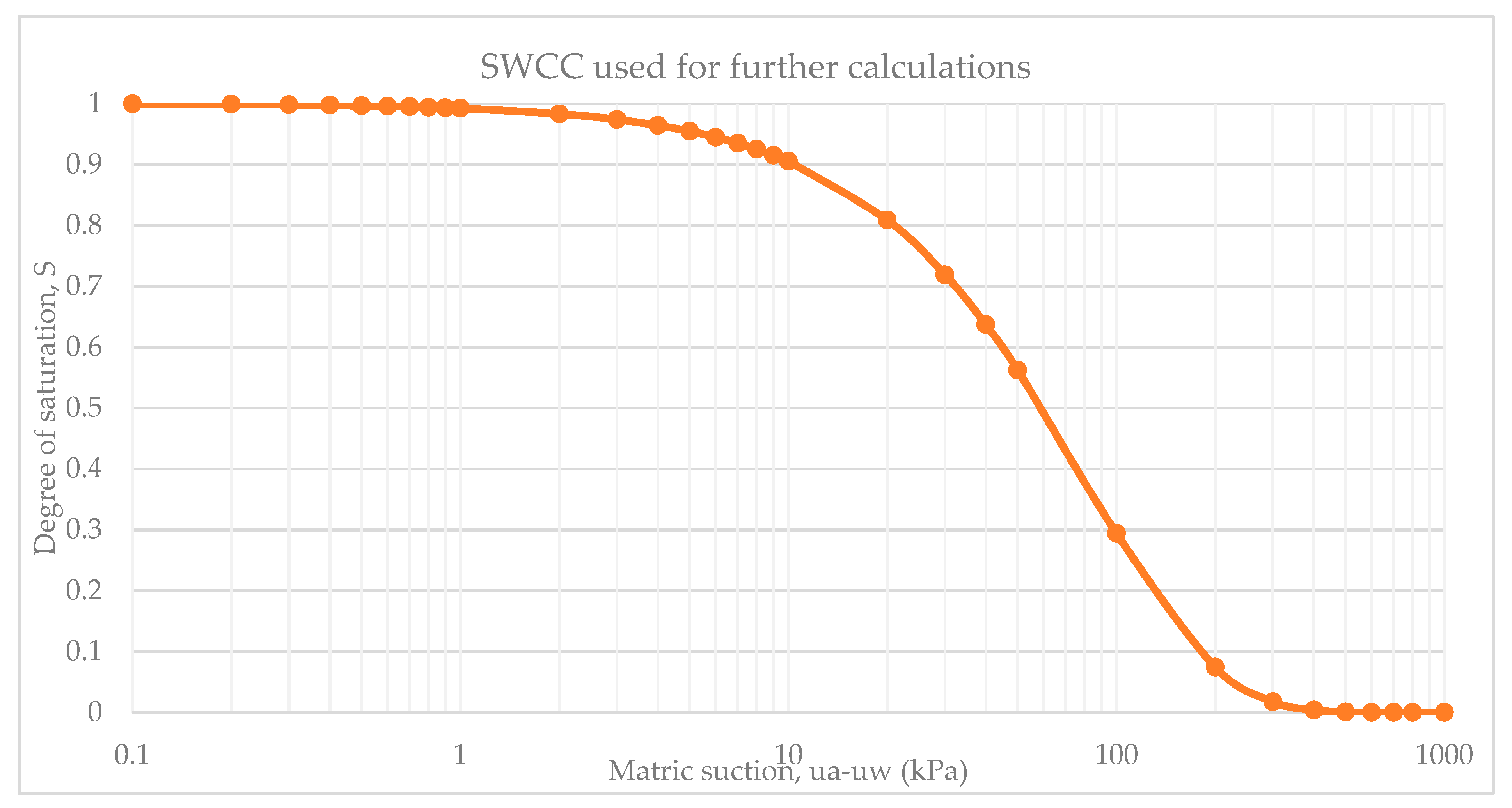
It is also essential to consider the soil–water characteristic curve (SWCC) in the design, incorporating unsaturated soil mechanics principles. This graph is a representation of the water content or degree of saturation against the logarithm of matric suction. The relationship between water content and matric suction is logarithmic. From the experimental data obtained, it was determined that SWCC depends on void ratio [26]. The smaller was the value of   e , the greater was the air entry value for the soil sample. If the air entry value is assumed to be 150 kPa, the graph for t a n ϕ b and χ t a n ϕ against the matric suction could be obtained. Using the correlation in SWCC, the effect of matric suction will be implemented in calculations of the shaft capacity of the piles.

3. Site Investigation

In order to calculate the shaft capacity of a single pile, the values of soil characteristics and dimensions of the pile are required. For these purposes, the soil profile and designed pile are taken from the final project report of building construction located in Kediri, Indonesia by Sinohydro and Victory JO companies [27]. The pile was taken as bored pile, with a diameter of 600 mm for both cases. In this paper, the resultant data were obtained from in situ testing and a specific pile was designed for different types of soils. Type 1 and Type 2 cases are used for calculations. The specification and design of works were performed following the Indonesian standard for geotechnical design based on SNI 8460 [28]. Table 1 shows the soil parameters used for further calculations.
As it is presented, the ground water level is located lower than the designed pile, so the pore water pressure is considered to be zero.

Type 2

Using the same approach, as for the Type 1 pile, the calculations were performed in order to calculate the shaft capacity of the Type 2 pile. Table 2 shows the soil parameters.
The contribution of the matric suction can be found through the SWCC and degree of saturation is found through correlation with volumetric water content ( θ w ). Figure 1 represents SWCC, the variation in the S with matric suction.
According to the curve, the parameters for matric suction and degree of saturation were found and represented in Table 3. Ground Water Table level was determined as 6.4 m.

4. Results

4.1. Type 1 Pile: α Method

The adhesion factor is found as a relation between the undrained shear strength and average effective stress. According to Sladen [29], the value for the adhesion factor is calculated as Equation (13):
α = C   ( σ 0 ¯ c u ) 0.45
where C = k   t a n δ , for bored piles C differs from 0.4 to 0.5; σ 0 —average effective stress; and c u —undrained shear strength [29].
The adhesion factor for the depth of 0–6 m was calculated and the resulting data are presented in Table 4.
In order to obtain the value for average vertical effective stress, Equation (14) is used:
σ = σ u
where σ —total stress σ = γ z ; u —pore water pressure u = w z [25].
Since the water level is located lower than the depth of the pile, the pore pressure is considered to be zero ( u   = 0). The vertical effective stress for each layer can be calculated using Equation (15).
σ = σ = γ z σ 1 = 18.3 3 = 54.9   kN m 2 σ 2 = 16.7 1 = 16.7   kN m 2 σ 3 = 16.4 2 = 32.8   kN m 2
Figure 2 represents the variation in the stresses with the embedment length of the pile in the soil.
In order to calculate the average value of the vertical effective stress, the area of each section was calculated and then divided by the total depth:
σ 0   ¯ = 82.35 + 35.8 + 49.5 6 = 22.47   kN / m 2
From the values calculated, the skin resistance of the pile foundation can be determined, where p = π D = π 0.6 = 1.885   m .
Table 5 shows the calculated values for three soil layers and resulting shaft capacity of the pile.

4.1.1. β Method

In order to calculate the value for K, Equation 16 is used for over-consolidated clays:
K = ( 1 sin ϕ R ) O C R
Table 6 represents the values of the overconsolidation ratio (OCR), friction angle, and effective stress [25].
Total shaft capacity of the pile can be found as:
For the depth of 0–3 m:
f 1 = ( 1 sin 31 ) tan 31 54.9 2 4 = 16   kN / m 2
For 3–4 m:
f 2 = ( 1 sin 25 ) tan 25 54.9 + 16.7 2 4 = 19.28   kN / m 2
For 4–6 m:
f 3 = ( 1 sin 25 ) tan 25 16.7 + 32.8 2 3.8 = 12.99   kN / m 2
Q s = ( f 1 + f 2 + f 3 ) p L = 1.885 ( 16 3 + 19.28 + 2 12.99 ) = 175.8   kN
As it can be seen, the obtained result for the shaft capacity is close to the value calculated using the α -method.

4.1.2. λ Method

In order to determine the value of λ , values from Vijayvergiya and Focht [30] are used, 6 m of embedment length converted to feet is equal to 19.7 feet. The obtained value for λ is found as ~0.29, so the resulting value for skin resistance is:
f a v e = 0.29 ( 22.47 2 96 3 + 66 + 42 2 6 ) = 48.9   kN / m 2
Q s = 1.885 6 48.9 = 552.6   kN
As can be seen, the value of the skin resistance is much higher than from the previous methods, so the method is not applicable for this case.

4.2. Type 2 Pile: α Method

Table 7 represents the obtained results for skin resistance using the α method.

β Method

For the depth of 0–1.5 m:
f 1 = ( 1 sin 31 ) tan 31 27.15 2 4 = 8   kN / m 2
For 1.5–5 m:
f 2 = ( 1 sin 31 ) tan 31 27.15 + 63.35 2 4 = 26.4   kN / m 2
For 5–6 m:
f 3 = ( 1 sin 25 ) tan 25 63.35 + 16.7 2 4 = 21.55   kN / m 2
Q s = ( f 1 + f 2 + f 3 ) p L = 1.885 ( 8 1.5 + 26.4 3.5 + 21.55 ) = 237.42   kN

4.3. Incorporation of the Matric Suction in Calculations of the Bearing Capacity

Effect of the consideration of unsaturated conditions can drastically change the values of the bearing capacity of the piles. Modified methods for unsaturated conditions are used in the calculation of shaft capacity for designing the pile.

4.4. Type 1 Soil

4.4.1. Modified β Method [7]

In order to calculate the shear strength of the soil, it is essential to consider the matric suction along with the degree of saturation. Equation (17) is used for the calculation of the shear strength.
τ = [ c + ( σ n u a ) t a n ϕ ] + [ ( u a u w ) S k t a n ϕ ]
where c —effective cohesion; ( σ n u a ) —net normal stress; ϕ —effective internal friction angle; ( u a u w ) —matric suction; S —degree of saturation; and k —fitting parameter [7].
The fitting parameter used for shear strength can be found though the graph showing its relation between Plasticity Index (PI). However, in the original document, there were no exact values for PI, so in order to find its value, a graph of the friction angle vs. PI was used [27] before finding the value of k . The fitting parameter can be calculated using Equation (18).
k = 0.0016 P I 2 + 0.0975 P I + 1
From the above methods, values of the fitting parameter were taken as shown in Table 8.
Using all the given and obtained data, the shear strength can be calculated and results are shown in Table 9.
Using Equation (19) of the modified beta method, the shaft capacity of a pile can be calculated.
Q s = [ β σ v + { ( u a u w ) S k t a n δ } ] π d L
where δ —effective angle of interface [7].
According to this and the values found before, Table 10 shows the results of the calculated ultimate shaft capacity. Values for β were considered to be the same as calculated in the previous conventional method.

4.4.2. Modified α Method [7]

The fitting parameter v is related to a type of the soil, and can be considered as one for coarse-grained and two for fine-grained [7]. In these calculations, this parameter is considered to be two.
The fitting parameter μ is dependant on the index of plasticity and can be taken as [7]:
μ = 9 ,   for   8 P I 15.5
μ = 2.1088 e 0.0903 PI ,   for   15.5 P I 60
As it known, for the first layer, where the PI is equal to 16, the μ was taken as 9; for clay layers, with a PI of 50, the calculated value of μ was 192.7.
Table 11 shows the calculated results of the undrained shear strength in unsaturated conditions.
Resulting values of c u ( u n s a t ) can be used to calculate the shaft bearing capacity of the soil using the modified alpha method (Equation (22)) [7].
Q s = α c u ( u n s a t ) π d L
Values of the shaft bearing capacity calculated using the modified alpha method are shown in Table 12. Values for α were taken from the calculations in previous methods.

4.4.3. Modified λ Method [7]

The shaft capacity using the modified lambda method can be determined using Equation (23) [7].
Q S = λ [ σ a v g + 2 c s a t ( 1 + u a u w ( P a 101.3 ) S v μ ) ] π d L
All needed values were calculated in previous methods, so the final resulting values for shaft capacity using the modified λ method are provided in Table 13. The value of λ was estimated from the graph by [30] as 0.29.

4.5. Type 2 Soil

Using the same approach, the values of shaft bearing capacity were estimated for the pile in the Type 2 soil profile.

Modified β Method [7]

Table 14 shows the calculated values for the shaft capacity of Type 2 soil using the modified β method; Table 15 shows the results for the modified alpha method; and Table 16 shows the values obtained using the modified λ method.

4.6. Tip Resistance

Total ultimate bearing capacity of the bored pile is determined by Equation (24) [25].
Q u l t = Q t + Q s
where Q t —tip resistance or end bearing capacity; Q s —shaft bearing capacity or skin friction of the pile.
Following the calculations made above, the end-bearing capacity for the Type 1 and Type 2 piles was calculated.
In saturated conditions, Q s can be calculated using Equation (25) [25]:
Q s = A p q p = A p ( c N c + q N q )
where A p —cross-sectional area of the pile; q p —unit resistance; q —effective vertical stress; N q ,   N c —bearing capacity factors; c —cohesion of a soil.
In unsaturated conditions, the end bearing capacity is found using Equation (26) [31]:
Q s = N c [ c + ( u a u w ) S k t a n δ ] A p
where ( u a u w )—matric suction; S—degree of saturation; k—fitting parameter; δ —degree of internal friction [31].
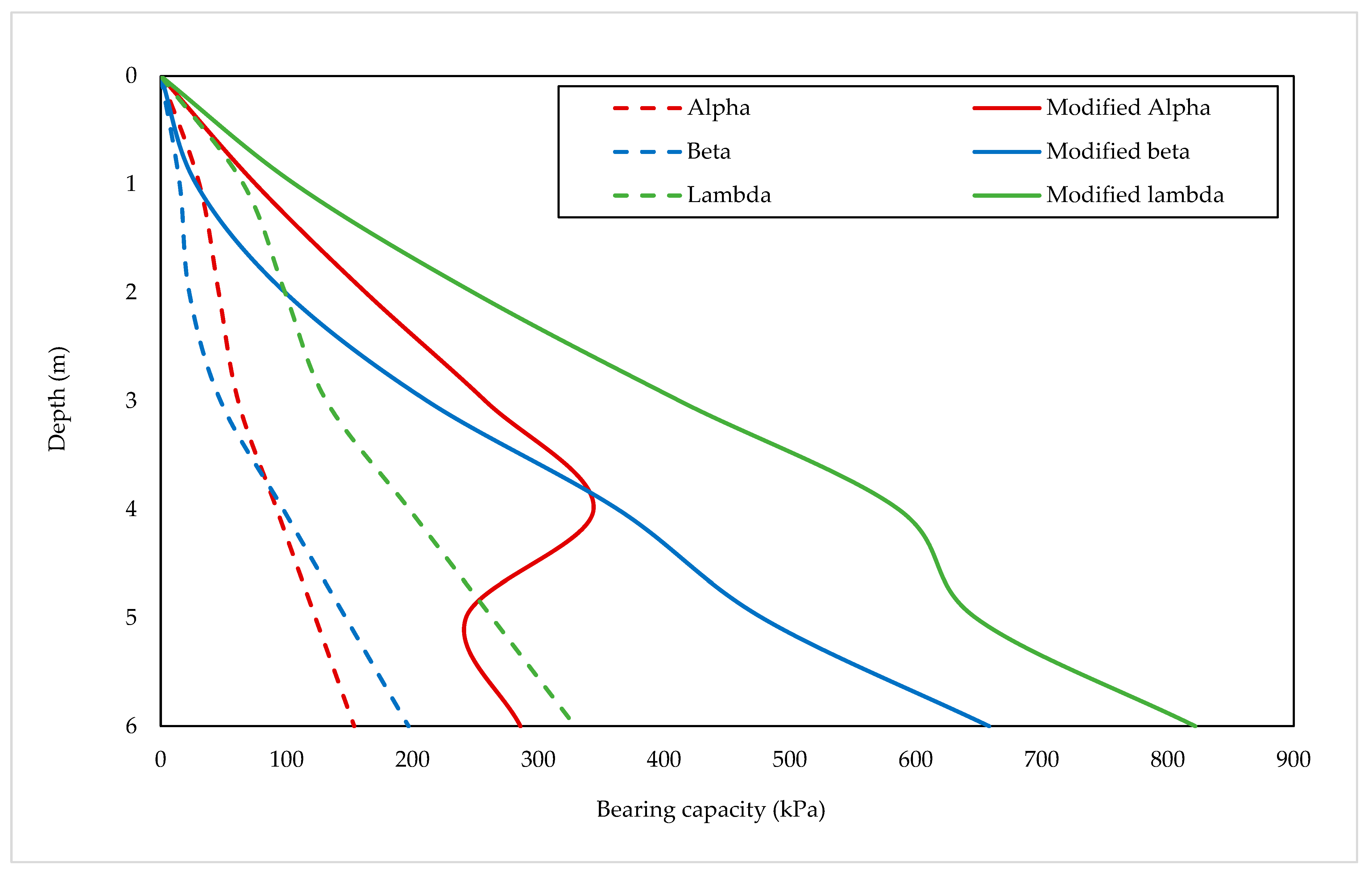
The bearing capacity of a single pile using traditional and modified α ,   β , and λ methods is presented in Table 17 and Table 18. In addition, data are represented in the form of graphs (Figure 3 and Figure 4).
Generally, the obtained results indicate the greater capacity of the pile in unsaturated conditions. For the Type 1 pile, the calculated shaft capacity undergoes a sudden decrease at the depth of 3 m due to the high value of the fitting parameter μ in the clay layers. This is the same for the Type 2 pile, where the decrease occurs at a depth of 4 m. Overall, in both saturated and unsaturated conditions, the λ method showed the biggest value of the shaft capacity and the beta method showed the lowest.

4.7. Matric Suction Variation

Matric suction is the most significant physical variable comprising unsaturated soil behavior. It is the energy change in the water condition transferred from its soil to a free state. In other words, matric suction can be defined at the soil-water-air representative elementary volume and represented as the difference between pore air pressure and pore water pressure (Equation (27)) [32].
ψ m = u a u w
The increase in soil moisture content clarifies the effect of rainfall infiltration on matric suction. Values of matric suction decrease with the increase in the rainfall volume. According to the in situ test conducted by Lim et al. [33], rainfall significantly affected the matric suction, mostly in the upper layers of the soil.
Although the experiment was performed to show slope stability, the definition of decreasing matric suction can also be implemented in this study. A decrease in matric suction leads to a decrease in bearing capacity, which can negatively affect the stability of the foundation.
To show the effect of the variation in matric suction, the original data were decreased by 100%, 75%, 50%, and 25%. The reduction in the matric suction is related to a total cohesion method, where the matric suction is considered as a “percentage of hydrostatic pore water pressure” [34]. The infiltration of the rainwater can decrease the matric suction in the upper layers and affect the factor of safety [34]. Figure 5, Figure 6, Figure 7, Figure 8, Figure 9 and Figure 10 show the comparison of the resultant values for shaft bearing capacities.
Reduction in the matric suction tends to decrease the pile capacity in both Type 1 and Type 2 cases. For the Type 1 pile, the effect of suction decrease does not severely affect the Qf except the great decrease in the values at the depth of 2 m for the modified α and λ methods. For Type 2 soil, the changes have the same trend and are noticeable at the depth of 4 m for the modified α and λ methods. According to the obtained results, changes in suction mostly affected the clay layers, where the capacity of the pile in Type 1 soil using the modified α and λ methods decreased by 24% and 22%, respectively, on average for every 25% decrease in suction. The same trend is noticed for the Type 2 soil at 4 m depth, pile capacity dropped by 21.5% using the modified α and 17% using the modified λ for every 25% change in matric suction. The sudden change in the pile capacity is explained by a fitting parameter μ . Estimations of μ   were made according to Oh and Vanapalli [35], where the relationship of the fitting parameter and plasticity index was derived based on limited data and usage shall be considered only with supporting evidence [35].

4.8. Change in GWT

A temporary increase in the ground water table occurs in the process of rainwater infiltration of unsaturated soil layers. In order to investigate the effect of the increase in GWT on the pile capacity, the obtained values for Type 1 and Type 2 piles were subjected to an increase in the saturation level. Table 19 and Table 20 show the decreasing trend of the pile capacity due to higher GWT.
Generally, the results show that an increase in the saturation level will lead to a decrease in pile total capacity. In the Type 1 pile, the change in the GWT by 3.2 m diminishes the capacity by 15%, 16.82%, and 6.98% for the modified α, β, and λ methods, respectively. This is the same for the Type 2 pile, increasing GWT by 3 m results in a decrease of 16.33%, 17.71%, and 9.92%, respectively. In accordance with the obtained data, the modified λ method is found to have less effect on the variation in the GWT.

5. Discussion

Overall, the trend shows that bearing capacity in unsaturated conditions is more significant than in saturated conditions. However, it can be seen that shaft bearing capacity decreases in the silt layer, where the Plasticity index was greater than 15.5, for which using the formula for the fitting parameter, μ was calculated as 192.7, whereas for the clay layer it was taken as 9 [36].
Moreover, it can be seen that the reduction in the matric suction decreases the bearing capacity of a pile, which will lead to an extreme settlement, tension cracks in the foundation, and even the collapse of the foundation [24,37]. However, the effect of matric suction on the bearing capacity using the modified β method is not severe. It can be explained by the degree of saturation of the soil. When the matric suction decreases, the positive change in the degree of saturation compensates the effect on the shaft capacity. On the contrary, the bearing capacity using the modified α and λ methods was greatly affected by matric suction. The maximum bearing capacity of the Type 2 pile using modified α and λ was 285.76 kPa and 821.8 kPa, respectively.
From the results of modified α and λ methods, for Type 1 pile, the significant difference in the results due to decrease in suction is noticed at a depth of 2 m. On the other hand, the maximum difference in bearing capacity results using the modified α and λ methods for the Type 2 pile is found at 4 m depth.

6. Conclusions

It can be concluded that incorporating the unsaturated conditions in the foundation design has a positive effect. Obtained values show a lower pile capacity in saturated conditions and a decrease in bearing pile capacity with a reduction in matric suction and an increase in GWT. The reason for this can justify the importance of the incorporation of rainfall infiltration in the advanced design of pile foundations. As the result of the suction variation, the most conservative method is found to be the modified β method. However, cost optimization shall be considered while choosing the method for the design. As for the increase in GWT, the modified λ method depicted the most conventional behavior. Following, these methods are concluded to be suitable in pile foundation design and the rainwater infiltration effect can be utilized for the factor of safety calculations. The possible rain infiltration decreases matric suction, mostly in the upper layers. In future research, it is necessary to continue the analysis using the Plaxis 3D software, to show the effect of matric suction on different penetration depths of the pile, and to investigate other real-case examples of designs of a pile foundation in unsaturated conditions. The investigation of the effect in changing suction and GWT can be useful for the proper design of the pile foundation in different climatic conditions and take into consideration increasing amounts of precipitation due to global warming. Considering not only the effect of the unsaturated soil mechanics but differences in saturation level makes the research applicable for estimation of potential hazards due to infiltration of water.

Author Contributions

Conceptualization: A.S. (Aizhan Sagu), A.S. (Alfrendo Satyanaga); Investigation: A.S. (Aizhan Sagu); Methodology: A.S. (Aizhan Sagu), N.G.; Writing—original draft: A.S. (Aizhan Sagu), A.S. (Alfrendo Satyanaga); Supervision: A.S. (Alfrendo Satyanaga), S.I., S.-W.M., J.K.; Funding acquisition: A.S. (Alfrendo Satyanaga); Resources: A.S. (Alfrendo Satyanaga); Data curation: N.G.; Validation: S.I.; Software: R.K.; Formal analysis: R.K.; Writing—review and editing: S.-W.M., J.K.; Project administration: J.K. All authors have read and agreed to the published version of the manuscript.

Funding

This research was supported by the Nazarbayev University Research Fund under Grants 11022021CRP1512 and 20122022FD4133. The authors are grateful for this support. Any opinions, findings, and conclusions or recommendations expressed in this material are those of the author(s) and do not necessarily reflect the views of the Nazarbayev University.

Institutional Review Board Statement

Not applicable.

Informed Consent Statement

Not applicable.

Data Availability Statement

Data is available upon request.

Acknowledgments

The Authors would like to express sincere gratitude for the tremendous assistance from laboratory technician during the collection of data for the study.

Conflicts of Interest

The authors declare no conflict of interest.

References

  1. Rahardjo, H.; Satyanaga, A.; Harnas, F.R.; Leong, E.C. Use of Dual Capillary Barrier as Cover System for a Sanitary Landfill in Singapore. Indian Geotech. J. 2016, 46, 228–238. [Google Scholar] [CrossRef]
  2. Kristo, C.; Rahardjo, H.; Satyanaga, A. Effect of hysteresis on the stability of residual soil slope. Int. Soil Water Conserv. Res. 2019, 7, 226–238. [Google Scholar] [CrossRef]
  3. Thornthwaite, C.W. An Approach toward a Rational Classification of Climate. Geogr. Rev. 1948, 38, 55–94. [Google Scholar] [CrossRef]
  4. Fredlund, D.G.; Raharjo, H.; Fredlund, M.D. Theory to Practice of Unsaturated Soil Mechanics. In Unsaturated Soil Mechanics in Engineering Practice; John Wiley & Sons, Inc.: Hoboken, NJ, USA, 2012; pp. 1–26. [Google Scholar]
  5. Zhai, Q.; Rahardjo, H.; Satyanaga, A.; Priono; Dai, G. Role of the pore-size distribution function on water flow in unsaturated soil. J. Zhejiang Univ.-Sci. A 2019, 20, 10–20. [Google Scholar] [CrossRef]
  6. Satyanaga, A.; Rahardjo, H. Unsaturated Shear Strength of Soil with Bimodal Soil-water Characteristic Curve. Geotechnique 2019, 69, 828–832. [Google Scholar] [CrossRef]
  7. Vanapalli, S.K.; Taylan, Z.N. Design of single piles using the mechanics of unsaturated soils. GEOMATE J. 2012, 2, 197–204. [Google Scholar] [CrossRef]
  8. Rahardjo, H.; Satyanaga, A.; Leong, E.C. Effects of rainfall characteristics on the stability of tropical residual soil slope. E3S Web Conf. 2016, 9, 15004. [Google Scholar] [CrossRef] [Green Version]
  9. Zhai, Q.; Rahardjo, H.; Satyanaga, A.; Dai, G. Estimation of the soil-water characteristic curve from the grain size distribution of coarse-grained soils. Eng. Geol. 2020, 267, 105502. [Google Scholar] [CrossRef]
  10. Sia, V.; Satyanaga, A.; Kim, Y. Effects of Heavy Rainfall on Shallow Foundations in Bukit Timah Granite in Singapore. Appl. Sci. 2022, 12, 9516. [Google Scholar] [CrossRef]
  11. Likos, W.J.; Song, X.; Xiao, M.; Cerato, A.; Lu, N. Fundamental challenges in unsaturated soil mechanics. In Geotechnical Fundamentals for Addressing New World Challenges; Springer: Berlin/Heidelberg, Germany, 2019; pp. 209–236. [Google Scholar]
  12. Zumrawi, M.M.; Abdelmarouf, A.O.; Gameil, A.E. Damages of buildings on expansive soils: Diagnosis and avoidance. Int. J. Multidiscip. Sci. Emerg. Res. 2017, 6, 108–116. [Google Scholar]
  13. Zhai, Q.; Rahardjo, H.; Satyanaga, A.; Zhu, Y.; Dai, G.; Zhao, X. Estimation of wetting hydraulic conductivity function for unsaturated sandy soil. Eng. Geol. 2021, 285, 106034. [Google Scholar] [CrossRef]
  14. Rahardjo, H.; Satyanaga, A. Application of Unsaturated Soil Mechanics to Open Pit Slope Stability; Australian Centre for Geomechanics, Nanyang Technological University: Singapore, 2014. [Google Scholar]
  15. Zhai, Q.; Rahardjo, H.; Satyanaga, A. Estimation of air permeability function from soil-water characteristic curve. Can. Geotech. J. 2019, 56, 505–513. [Google Scholar] [CrossRef]
  16. Topa, J. How Rain Affects Your Foundation, Residential Blog Posts. 28 September 2018. Available online: https://www.heliconusa.com/blog-1/2018/09/28/how-rain-affects-your-foundation/ (accessed on 1 November 2022).
  17. Zhanabayeva, A.; Sagidullina, N.; Kim, J.; Satyanaga, A.; Lee, D.; Moon, S.-W. Comparative Analysis of Kazakhstani and European Design Specifications: Raft Foundation, Pile Foundation, and Piled Raft Foundation. Appl. Sci. 2021, 11, 3099. [Google Scholar] [CrossRef]
  18. Zhang, W.; Huang, Y. Three-dimensional numerical investigation of mixed-mode debonding of FRP-concrete interface using a cohesive zone model. Constr. Build. Mater. 2022, 350, 128818. [Google Scholar] [CrossRef]
  19. Huang, H.; Li, M.; Yuan, Y.; Bai, H. Theoretical analysis on the lateral drift of precast concrete frame with replaceable artificial controllable plastic hinges. J. Build. Eng. 2022, 62, 105386. [Google Scholar] [CrossRef]
  20. Yuan, J.; Gan, Y.; Chen, J.; Tan, S.; Zhao, J. Experimental research on consolidation creep characteristics and microstructure evolution of soft soil. Front. Mater. 2023, 10, 70. [Google Scholar] [CrossRef]
  21. Zhang, C.; Yin, Y.; Yan, H.; Zhu, S.; Li, B.; Hou, X.; Yang, Y. Centrifuge modeling of multi-row stabilizing piles reinforced reservoir landslide with different row spacings. Landslides 2022, 20, 559–577. [Google Scholar] [CrossRef]
  22. Li, J.; Zhou, L.; Li, S.; Lin, G.; Ding, Z. Soil–structure interaction analysis of nuclear power plant considering three-dimensional surface topographic irregularities based on automatic octree mesh. Eng. Struct. 2023, 275, 115161. [Google Scholar] [CrossRef]
  23. Li, J.; Chen, M.; Li, Z. Improved soil–structure interaction model considering time-lag effect. Comput. Geotech. 2022, 148, 104835. [Google Scholar] [CrossRef]
  24. Zhanabayeva, A.; Moon, S.-W.; Ocheme, J.I.; Shokbarov, Y.; Khomyakov, V.; Kim, J.; Satyanaga, A. Comparative Analysis of Seismic Design Codes for Shallow Foundations Adhering to the Kazakhstani and European Approaches. Sustainability 2023, 15, 615. [Google Scholar] [CrossRef]
  25. Das, B.M.; Sivakugan, N. Principles of Foundation Engineering; Cengage Learning: Boston, MA, USA, 2018. [Google Scholar]
  26. Li, X.W.; Zhou, C.L.; Zhang, Z.Q. Study on Wide-Deep Strip Foundations Resting on Unsaturated Soils. Iran. J. Sci. Technol. Trans. Civ. Eng. 2020, 45, 253–267. [Google Scholar] [CrossRef]
  27. Syhohydro, V.J. Design MSEW. Dhoho Airport Project Kediri. Technical report. Date of issued: February 2022. 11/DST210090/21-12/008T/LP-04/A3. pp. 134. Available online: https://davysukamta.com/portfolio/ground-improvement-works-under-mse-wall-dhoho-airport-kediri/ (accessed on 6 March 2023).
  28. SNI 8460; Persyaratan Perancangan Geoteknik; BSN: Kuala Lumpur, Malaysia, 2017.
  29. Sladen, J.A. The adhesion factor: Applications and limitations. Can. Geotech. J. 1992, 29, 322–326. [Google Scholar] [CrossRef]
  30. Vijayvergiya, V.; Focht, J. A new way to predict the capacity of piles in clay. In Proceedings of the 4th Annual Offshore Technology Conference, Houston, TX, USA, 30 April 1972; Volume 2, pp. 865–874. [Google Scholar]
  31. Thota, S.K.; Vahedifard, F. A model for ultimate bearing capacity of piles in unsaturated soils under elevated temperatures. E3S Web Conf. 2020, 205, 05003. [Google Scholar] [CrossRef]
  32. Zhang, C.; Lu, N. Unitary definition of matric suction. J. Geotech. Geoenviron. Eng. 2019, 145, 02818004. [Google Scholar] [CrossRef]
  33. Lim, T.T.; Rahardjo, H.; Chang, M.F.; Fredlund, D.G. Effect of rainfall on matric suctions in a residual soil slope. Can. Geotech. J. 1996, 33, 618–628. [Google Scholar] [CrossRef]
  34. Rahardjo, H.; Satyanaga, A.; Leong, E.C.; Wang, J.-Y. Comprehensive Instrumentation for Real Time Monitoring of Flux Boundary Conditions in Slope. Procedia Earth Planet. Sci. 2014, 9, 23–43. [Google Scholar] [CrossRef] [Green Version]
  35. Oh, W.T.; Vanapalli, S.K. A simple method to estimate the bearing capacity of unsaturated fine-grained soils. In Proceedings of the 62nd Canadian Geotechnical Conference, Halifax, NS, Canada, 20–23 September 2009; pp. 234–241. [Google Scholar]
  36. Zhanabayeva, A.; Abdialim, S.; Satyanaga, A.; Kim, J.; Moon, S.W. Comparative Analysis of International Codes of Practice for Pile Foundation Design Considering Negative Skin Friction. Int. J. Geo-Eng. 2022, 13, 11. [Google Scholar] [CrossRef]
  37. Shaldykova, A.; Moon, S.W.; Kim, J.; Lee, D.; Ku, T.; Zhussupbekov, A. Comparative Analysis of Kazakhstani and European Approaches for the Design of Shallow Foundations. Appl. Sci. 2020, 10, 2920. [Google Scholar] [CrossRef] [Green Version]
Figure 1. SWCC used for determination of the degree of saturation.
Applsci 13 03968 g001
Figure 2. Variation in the vertical effective stress.
Applsci 13 03968 g002
Figure 3. Pile bearing capacity of saturated and unsaturated soil Type 1 using α , β , and λ methods vs. depth.
Applsci 13 03968 g003
Figure 4. Pile bearing capacity of saturated and unsaturated soil Type 2 using α , β , and λ methods vs. depth.
Applsci 13 03968 g004
Figure 5. Pile bearing capacity in unsaturated soil Type 1 using modified α method vs. depth with variating matric suction.
Applsci 13 03968 g005
Figure 6. Pile bearing capacity in unsaturated soil Type 1 using modified β method vs. depth with variating matric suction.
Applsci 13 03968 g006
Figure 7. Pile bearing capacity in unsaturated soil Type 1 using modified λ method vs. depth with variating matric suction.
Applsci 13 03968 g007
Figure 8. Pile bearing capacity in unsaturated soil Type 2 using modified α method vs. depth with variating matric suction.
Applsci 13 03968 g008
Figure 9. Pile bearing capacity in unsaturated soil Type 2 using modified β method vs. depth with variating matric suction.
Applsci 13 03968 g009
Figure 10. Pile bearing capacity in unsaturated soil Type 2 using modified λ method vs. depth with variating matric suction.
Applsci 13 03968 g010
Table 1. Soil parameters for Type 1 borehole [27].
Soil TypeDepth, m γ s a t ,   kN / m 3 γ b u l k ,   kN / m 3 E 50 ,   kPa φ ,   Degrees c ,   kPa s u ,   kPa NmOCR
Silt018.318.316,000319.696160.74
Clay316.716.711,000256.666110.74
Clay416.416.47000254.24270.73.8
Silt6.518.318.320,0003112.0120200.74
Silt8.6519.019.050,0003130.0300500.74
Silt1018.818.842,0003125.2252420.74
Silt1218.618.629,0003117.4174290.74
Silt19.1518.918.944,0003126.4264440.74
Table 2. Soil parameters for Type 2 borehole [27].
Soil Type γ s a t ,   kN / m 3 γ b u l k ,   kN / m 3 E 50 ,   kPa φ ,   Degrees c ,   kPa s u ,   kPa NmOCR
Silt18.118.16000313.63660.74
Clay16.716.712,000257.272120.74
Clay17.717.728,0002516.8168280.74
Clay17.617.625,0002515.0150250.74
Silt18.718.734,0003120.4204340.74
Table 3. Values of matric suction and degree of saturation with changing depth.
Depth (m) Matric   Suction ,   u a u w   ( kPa ) Degree   of   Saturation ,   S
0640.45
1540.52
2440.6
3340.68
4240.77
5140.86
640.96
Table 4. Calculated values for adhesion factor.
Depth (m) Average   Vertical   Effective   Stress   σ 0   ( kN / m 2 ) Undrained   Shear   Strength   c u   ( kPa ) Adhesion   Factor   α
0–322.47960.234
3–422.47660.277
4–622.47420.340
Table 5. Calculation of the shaft capacity using α method.
Depth (m) L   ( m ) s u ( kPa ) α α s u p L   ( kN )
0–33960.234131.9
3–41660.27734.46
4–62420.34053.84
Total220.2
Table 6. Values of the soil parameters.
DepthOCR Friction   Angle   ϕ R   ( ° ) Effective   Stress   σ 0   ( kPa )
0–343154.9
3–442516.7
4–63.82532.8
Table 7. Calculation of the shaft capacity using α method.
Depth (m) L   ( m ) s u ( kPa ) α α s u p L   ( kN )
0–1.51.5360.45346.11
1.5–53.5360.453107.6
5–61720.33244.99
Total198.7
Table 8. Fitting parameter values for different depths.
Depth (m) Friction   Angle ,   ϕ Plasticity Index, PIFitting Parameter, k
0–331162.1504
3–425501.875
4–625501.875
Table 9. Calculated values for shear strength.
c   ( kPa ) σ n u a   ( kPa ) u a u w   ( kPa ) Sk t a n ϕ τ   ( kPa )
9.60640.452.150.6008606216.5081319
9.618.3540.522.150.6008606228.5495498
9.636.6440.62.150.6008606240.4070932
6.650.1340.681.8750.4663076637.6551898
6.666.8240.771.8750.4663076644.6050846
4.282140.861.8750.4663076647.3574554
4.298.440.961.8750.4663076651.8124641
Table 10. Calculated values for shaft capacity using β method.
Depth (m) β σ v   ( kPa ) Q s   ( kPa )
00.582800
10.582818.329.50
20.582836.6101.23
30.582850.1180.40
40.582866.8304.25
50.582882435.13
60.582898.4596.28
Table 11. Calculated values of c u ( u n s a t ) .
c u ( s a t ) u a u w P a S v μ c u ( u n s a t )
96.064.0101.30.4529234.2
96.054.0101.30.5229251.7
96.044.0101.30.629264.9
66.034.0101.30.682192.771.4
66.024.0101.30.772192.770.9
42.014.0101.30.862192.744.3
42.04.0101.30.962192.742.8
Table 12. Calculated Q s values using modified α method.
α c u ( u n s a t ) π d   ( m ) L   ( m ) Q s   ( kPa )
0.234234.23.140.600
0.234251.73.140.61110.97
0.234264.93.140.62233.58
0.27771.43.140.63111.76
0.27770.93.140.64147.94
0.3444.33.140.65141.74
0.3442.83.140.66164.51
Table 13. Calculated values of Q S using modified λ method.
Length (m) λ Q S   ( kPa )
00.290
10.29285.05
20.29618.96
30.29316.12
40.29455.76
50.29465.81
60.29603.20
Table 14. Values of shaft capacity of Type 2 using modified β method.
Depth (m) β σ v   ( kPa ) Q s   ( kPa )
00.582800
10.582818.228.28
20.582836.499.10
30.582854.6211.84
40.582872.8363.16
50.538583.5477.99
60.5385100.2658.14
Table 15. Values of shaft capacity of Type 2 using modified α method.
α c u ( u n s a t ) π d   ( m ) L   ( m ) Q s   ( kPa )
0.453843.140.600
0.45388.63.140.6176.65
0.45395.53.140.62162.96
0.453100.83.140.63258.04
0.453100.73.140.64343.84
0.33277.53.140.65242.49
0.33276.13.140.66285.76
Table 16. Values of shaft capacity of Type 2 using modified λ method.
Length (m) λ Q S   ( kPa )
00.290
10.29106.85
20.29248.64
30.29412.50
40.29586.22
50.29647.64
60.29821.80
Table 17. Comparison of bearing capacity for soil Type 1 under saturated and unsaturated soil conditions.
SaturatedUnsaturated
Depth, mBearing Capacity, kPaDepth, mBearing Capacity, kPa
α βλ Modified   α Modified βModified λ
00000000
142.3430.1692.181110.9729.50285.05
284.6860.32184.352233.58101.23618.96
3127.0290.48276.533111.76180.40316.12
4161.48126.82368.714147.94304.25455.76
5188.40151.31460.885141.74435.13465.81
6215.32175.80553.066164.51596.28603.20
Table 18. Comparison of bearing capacity for soil Type 2 under saturated and unsaturated soil conditions.
SaturatedUnsaturated
Depth, mBearing Capacity, kPaDepth, mBearing Capacity, kPa
α βλ Modified   α Modified βModified λ
00000000
130.7415.0865.84175.6528.28106.85
1.546.1122.6298.762162.9699.10248.64
261.4847.50131.693258.04211.84412.50
392.2297.27197.534343.84363.16586.22
4122.96147.03263.375242.49477.99647.64
5153.70196.79329.226285.76658.14821.80
6198.76237.42395.06
Table 19. Capacity of Type 1 pile under changing GWT.
GWTα Methodβ Methodλ Method
Qf (kPa)% DecreaseQf (kPa)% DecreaseQf (kPa)% Decrease
6.4164.51 596.28 603.20
4.8152.167.51546.128.41582.143.49
3.2139.8115.01495.9716.82561.076.98
1.6127.4622.52445.8125.24540.0010.48
0115.1130.03395.6533.65518.9413.97
Table 20. Capacity of Type 20 pile under changing GWT.
GWT𝛼 Methodβ Methodλ Method
Qf (kPa)% DecreaseQf (kPa)% DecreaseQf (kPa)% Decrease
7.5285.76 648.20 821.80
6270.215.44609.945.90794.633.31
4.5254.6610.89571.6811.80767.466.61
3239.1116.33533.4217.71740.289.92
1.5223.5521.77495.1623.61713.1113.22
0208.0027.21456.9029.51685.9416.53
Disclaimer/Publisher’s Note: The statements, opinions and data contained in all publications are solely those of the individual author(s) and contributor(s) and not of MDPI and/or the editor(s). MDPI and/or the editor(s) disclaim responsibility for any injury to people or property resulting from any ideas, methods, instructions or products referred to in the content.

