Abstract
Anchor-type foundations are one of the foundation types used in structures subject to tensile forces. These anchors are generally designed according to the weight of the soil on them depending on the depth they are buried at and the frictional resistance obtained from the failure surfaces during failure. One method of increasing the uplift capacity of the foundation without increasing the burial depth is the use of geogrid material. In this study, the uplift capacities of strip anchor plates at different embedment depths were investigated by considering the geogrid effect placed in different combinations. The aim of the study is to investigate whether a more economical solution can be obtained by using geogrid without increasing the embedment depth of the anchor plate. Experiments were carried out using centrifugal experimental setup, which gives values closer to the real results. The tests were performed on sand of two different densities for anchor burial depths H/B = 2 and H/B = 5. According to the results, the uplift capacity is significantly improved when geogrid is used. As the reinforcement configuration, the use of a single geogrid layer placed just above the anchor plate with an inclination angle of 45 degrees gave more effective results than using the geogrid horizontally and vertically. In the study, up to 98% increases in uplift capacity were obtained with reinforcement. In addition, the prototype model was analyzed with a numerical program based on the finite element method, and the results were compared with the experimental results. As a result of the comparison, it was observed that the experimental and numerical results were compatible with each other. Suggestions for practice are presented using the results obtained.
1. Introduction
Foundations are generally designed according to pressure loads acting in the vertical direction. However, many foundations are exposed to uplift loads due to both the type of load acting on them and structural reasons, such as with towers, offshore structures, traffic signs, buried pipelines, and tunnels [1,2,3,4]. The most important factor affecting the design of foundations is the behavior of the soil in which they are located. While soils have a certain capacity under pressure loads, their tensile strength is negligible. In order to absorb the tensile forces from the structures by the foundation, it is the most practical method to use the soil weight on the foundation by burying it in the soil. However, sometimes it is impractical to bury the foundation too deeply under extreme uplift loads, especially in soils where the groundwater level is high. In this case, the need arises to increase the uplift capacity of the foundation by improving the soil. In the literature, foundations are defined as anchors, and there are many studies on uplift behavior. These studies are usually in the form of small-scale laboratory studies or numerical studies on unreinforced soil.
Dickin and Leung [5] presented the centrifugal test results to investigate the uplift behavior of anchor plates. In the study, obtained test results were compared with theoretical methods.
Chattopadhyay and Pise [6] proposed a theoretical model for determining the break-out resistance of horizontal plate anchors. The obtained results showed that the Foster proposed method can predict the break-out factors for a wide range of values of the shear resistance angle of the sand.
In the experimental study carried out by Dickin [7], the uplift capacity of the anchors was investigated using a centrifugal test device. In the study, the effects of anchor geometry, embedment depth, and sand density parameters on the uplift capacity were investigated. According to the results of the tests, it was observed that the uplift capacity increased depending on the increase in anchor size, embedment depth, and the density of the sand.
An expression estimating the pull-out capacity of a horizontal strip plate was developed by Frydman and Shaham [8]. The expression was obtained using the experimental work performed within the scope of the study and the experimental results available in the literature.
In the experimental study carried out by Dickin and Leung [9] using a centrifuge, the uplift capacity of sand-embedded enlarged-base piles was investigated. In the study, the effects of burial depth, base diameter, and sand density were examined. According to the results obtained, the uplift capacity in loose sand was lower than the results obtained from the studies available in the literature, while the values obtained for compact sand were found to be compatible with the results of the previous study.
Dickin and Leung [10] performed centrifugal model tests to investigate the uplift capacity of belled piers in sand. According to the test results, an empirical design method was proposed for belled piers using the parameters of the foundation geometry.
A theoretical and experimental study was carried out by Ghaly and Clemence [11] to investigate the pull-out behavior of inclined helical screw anchors. Calculation of pull-out capacity is expressed theoretically in terms of relative depth and inclination angle. In the study, the theoretical and experimental results were compared and it was seen that they were in good agreement.
Dickin and Laman [12] compared the lifting capacity values of the strip anchor plates obtained using centrifuge experiments with the numerical analysis results using the finite element method. In the study, it was observed that the experimental and numerical results were in very good agreement until the anchor embedding ratio was 6, while there was some difference in the embedding ratios greater than 6.
In the experimental study carried out by Bildik and Laman [13] using small-scale laboratory tests, the uplift capacity behavior of anchor plates of different sizes and geometries buried in sand was investigated. In addition, the effects of sand density and different embedding rates on the uplift capacity behavior were investigated. From the experimental results, it was determined that the density of the sand soil and the embedding rate of the anchor plate significantly affect the uplift capacity. Comparing the obtained results with the existing theoretical methods, it has been seen that the values obtained in the case of dense sand are more consistent than in the case of loose sand.
In the study by Wang et al. [14], a finite element approach was developed to simulate the keying process of anchor plates embedded in normal consolidated clay. According to the results obtained from the study, it is stated that the loading eccentricity should not be less than half of the anchor width for a correct design in anchor keying.
Bera [15] carried out an experimental research on the uplift capacity of anchors. In the study, model tests were carried out in order to examine the effects of parameters such as the density of the sand and the embedment depth of the anchor. According to the results obtained from the experiments, it was observed that the uplift capacity of the anchor increased depending on the increase in the embedment depth. Using the test results, a nonlinear power model was developed that gives the uplift capacity of the anchor.
Niroumand and Kassim [16] carried out experimental and numerical studies to determine the uplift capacity of circular anchor plates. At the end of the study, it was found that the uplift capacity behavior of the circular anchor plates was experimentally and numerically compatible, and it was stated that the numerical results gave higher values in the loose sand condition than the experimental results.
Model experiments were carried out by Niroumand and Kassim [17] to examine the uplift behavior of rectangular anchor plates. In addition, the model experimental setup was numerically modeled with the finite element method and it was seen that the results obtained were compatible with each other. In the analyses performed using the finite element method, the sand soil was modeled with the Hardening Soil model. The research showed that the finite element results for the dense and loose cases of sand soil are higher than the experimental findings.
Zhu et al. [18] carried out a study including laboratory and field experiments to examine the uplift capacity of a new umbrella-shaped anchor type embedded in clay soil. According to the results of the experiments, they stated that the umbrella-shaped anchor has a higher uplift capacity than the conventional anchors.
Schiavon et al. [19] investigated the behavior of a single helical anchor plate embedded in sand under uniaxial tensile monotonic and cyclic loadings by centrifuge tests. The results contribute to clarify the impact of the number of cycles and load amplitude on anchor performance.
These studies show that the most important factors affecting the uplift capacity of the anchor plates are the dimensions of the anchor plate, the depth of burial, and the density of the soil. However, in some cases, increasing the anchor size and burial depth is not economical and feasible as it increases both the amount of excavation and the amount of backfill.
Various methods are used to increase the uplift capacity performance of anchor plates. One of these methods is the use of geosynthetics, which have become widespread, especially in recent years, and contribute to the tensile capacity of the soil. Geogrids placed in the soil are used to increase the uplift capacity of the anchors. Studies on reinforced soils are more limited than unreinforced cases [20,21,22,23,24,25].
Krishnaswamy and Parashar [20] investigated the uplift behavior of anchor plates in cohesive and cohesionless soils reinforced with geogrid and unreinforced cases by performing small-scale model experiments. According to the results, they stated that the uplift capacity can be increased by using geosynthetics in both cohesive and cohesionless soils.
In the study performed by Ilamparuthi and Dickin [21], the effect of soil reinforcement on the uplift capacity of model-belled piles and piers with various geometries embedded in the sand was investigated. According to the results, the uplift response increases with geogrid cell diameter, sand density, pile bell diameter, and embedment depth.
Niroumand et al. [22,23] reported experimental and numerical analysis results of the uplift capacity of anchor plates with and without geogrid and grid-fixed reinforcement. At the end of the study, it was shown that using reinforcements significantly improved the uplift capacity.
Keskin [24] carried out experimental and numerical studies on the uplift capacity of square anchor plates. In the tests, geogrids were used to reinforce the sand. The parameters investigated the effects of the depth of the geogrid, the distance between the geogrids, the reinforcement length, the burial depth, and the sand density. According to the results obtained, the uplift capacity of square plate anchors in sand can be significantly increased with geogrid reinforcement. In addition, it was stated that the burial depth and the relative density of the sand are parameters that greatly affect the uplift capacity.
Choudhary et al. [25] investigated the uplift performance of horizontal anchor plates in geocell-reinforced sand soils with model tests. In unreinforced conditions, it has been observed that failure occurs at displacement of 3% of the anchor plate width. Additionally, in the case of using geocell and geotextile layer, the uplift capacity increased approximately 4.5 times. The optimum geocell length was found to be 5.4 times the anchor width.
When the literature is evaluated, it is seen that the experimental studies on the behavior of foundations subjected to uplift force generally cover small-scale laboratory experiments, and the number of studies using geogrid reinforcement is quite small. The fact that the uplift capacities of geogrid reinforced anchors have not been investigated by centrifuge tests stands out as an important shortcoming. The most important difference of this study from the studies in the literature is that the uplift capacity of anchor plates in reinforced soil is investigated by centrifuge tests. In the study, the effect of sand density on uplift capacity was investigated in both unreinforced and reinforced conditions. The experiments were carried out at two different burial depths and the optimum reinforcement arrangement was investigated by placing the geogrid in different geometric conditions in the tests. Finite element analyses were carried out using the prototype model of the experimental setup and the analysis results were compared with the experimental results. The findings obtained from the study showed that the burial depth and sand density significantly affect the uplift capacity, the uplift capacity of the anchor plate can be increased by using geogrid reinforcement, and the uplift capacity can be increased by placing the geogrid reinforcement into the soil at different angles.
The structural framework of this article is as follows. Section 2 introduces the centrifuge experimental setup and presents the experimental program and the results of the experiments with and without reinforcement. Section 3 describes the results of the finite element analysis performed using the prototype model. Comparison and discussion of the experimental and numerical results obtained are presented in Section 4. Section 5 draws the conclusions.
2. Experimental Study
Experimental investigations within the scope of this study were carried out in the University of Liverpool centrifuge experimental setup. Centrifuge modeling, the test program, and the results obtained from tests are explained in this section.
2.1. Centrifuge Setup
Experimental studies were carried out in the centrifuge setup at the Liverpool University, and the setup details are presented in the study of Dickin and Leung [5]. The image of the centrifuge setup used is presented in Figure 1, and its schematic representation is presented in Figure 2. The centrifuge setup used in the experiments included balanced swinging buckets with a length of 0.57 m, a width of 0.45 m, and a depth of 0.23 m. In the experiments, the uplift force was applied upwards at a loading rate of 0.3 mm/min.
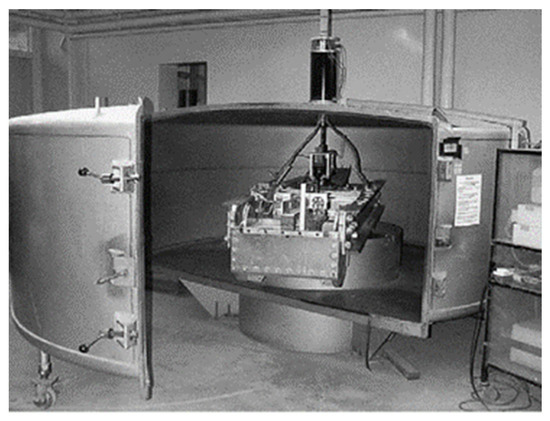
Figure 1.
Centrifuge setup [26].
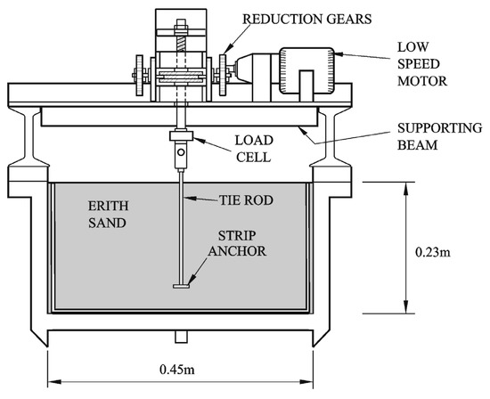
Figure 2.
Schematic view of centrifuge package and strip anchors.
2.2. Model Anchor Plate
Uplift tests were performed on a model strip anchor plate which was fabricated from mild steel with t = 5 mm thickness. In the tests, model strip anchor has a width of B = 30 mm, and a length of L = 150 mm was used (Figure 3). The uplift load applied to the model strip anchor is provided by using a tie rod fixed by screwing to the center of the plate.
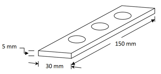
Figure 3.
Model anchor plate.
2.3. Properties of Sand
In the experiments, clean, fine, dry Erith sand was used (Table 1). The grain sizes of 80% of the sand were 0.125 and 0.25 mm with a mean grain size D50 of 0.20 mm. The sand was therefore essentially uniform with a coefficient of uniformity Cu of approximately 1.50. The experiments were conducted in loose and dense conditions of the sand material in order to determine the effect of the density of the sand on the uplift capacity. While creating the loose sand conditions, the soil was filled from a cone into the experimental setup in a controlled manner. Dense sand conditions were provided by mechanical compaction of 25 mm thick layers by means of a small vibrator. This method has been validated in previous studies by Dickin and Leung [9]. The average unit weight values obtained for the loose and dense condition of the sand samples prepared using the method described above were 14.5 and 16.4 kN/m3, respectively. Relative density of sand, Dr, corresponds to unit weights are Dr = 35% for loose condition and Dr = 75% for dense condition. The estimated internal friction angle, Ø, of the sand determined from triaxial tests using specimens at the same relative densities were 35 and 51°, respectively.

Table 1.
Properties of sand.
2.4. Details of Geogrid Reinforcement
A geogrid commercially known as nova curtain net with tensile strength of 30 kN/m was used as reinforcing material in the tests. The properties of the geogrid as listed by the manufacturer are given in Table 2.
Table 2.
Properties of geogrid.
2.5. Centrifuge Tests and Test Program
In the experimental study, centrifuge tests were carried out for two different sand densities, loose and dense. Results were obtained for two different ratios of embedment depth, H, and anchor plate width, B. Experiments were carried out in both unreinforced and reinforced conditions. In the experiments carried out for the reinforced case, the uplift capacity values were obtained when the geogrid reinforcement was placed at three different angles just above the anchor plate. In the experiments, the geogrid reinforcement length was chosen as 150 mm, with five times the anchor plate width. The configurations of the geogrid in the tests are shown in Figure 4. Centrifuge test program details are shown in Table 3.
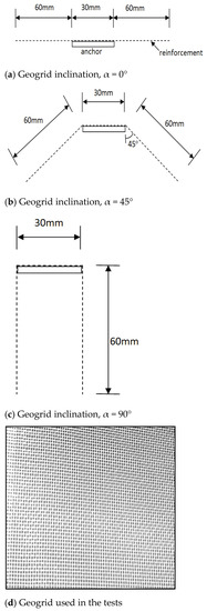
Figure 4.
Configuration of geogrid reinforcement used in centrifuge tests.
Table 3.
Centrifuge test program.
Test series 1 was carried out within the scope of centrifuge experiments, and the effect of anchor plate embedment depth on the uplift capacity was investigated. In test series 2, we aimed to examine the effect of the density of the sand on the uplift capacity. Test series 3, 4, 5, and 6 include the investigation of the effect of geogrid configuration on the uplift capacity of the anchor plate at different densities of sand and embedding ratios.
N = 33.3 g acceleration was applied in the centrifuge setup to ensure that the model strip anchor provides the 1 m width prototype conditions. In this case, the prototype anchor dimensions were brought to: BP = N.BM, LP = N.LM, and tp = N.tM by applying N times the gravitational acceleration, where B, L, and t are the width, length, and thickness of the anchor plate, respectively. P and M subscripts show the prototype and model, respectively. Thus, prototype uplift force, QUP = N2 times model uplift force QUM.
2.6. Centrifuge Test Results
To determine the uplift capacity, tests were completed after a vertical displacement of d = 12 mm (prototype value dp = 0.36 m), which corresponds to a higher capacity than the ultimate uplift capacity. The relationship between uplift capacity and displacement in unreinforced sand is shown in Figure 5. The peak value was reached in most of the experiments, and the uplift capacity/displacement curve obtained in dense sand for an embedment ratio of H/B = 5, is typically presented in Figure 5. As generally known for the uplift behavior of anchors, the outer failure plane developed at smaller deformations than the second inner plane obtained at much greater strains. At this depth, a failure plane was not obtained for the loose sand conditions. As seen the anchor quickly reaches its maximum uplift capacity in dense sand. The corresponding failure displacements increased significantly as the embedment ratio of the anchors increased from H/B = 2 to H/B = 5. In both cases, further displacement appears to cause a steady decrease in uplift capacity. This post-peak behavior has been observed in a study reported by Dickin [7] for different shapes of non-reinforced anchors. In loose sand conditions, the peak uplift capacities of buried anchors at shallow depths were more pronounced, while softening occurred after reaching the peak uplift capacity in deeper anchors. Ultimate bearing capacities occurred after slightly higher deformations than under dense sand conditions. Depending on the increase in the density of the sand material, the uplift capacity of the anchor increased by 19% when the embedding ratio was H/B = 2, and 55% when the embedding ratio was H/B = 5. The results obtained in soil reinforced with a single geogrid of 150 mm length are presented in Figure 6. When the curves in Figure 6 are examined, it is seen that the rate of increase in the uplift capacity of the anchor plates is less than 20% in both loose and dense sand conditions. A much greater increase in the uplift capacity of the anchor was obtained when the geogrid was placed with a 45-degree inclination as shown in Figure 4b. This increased rate was 96 and 27% in dense sand and 73 and 29% in loose sand at embedment ratios 2 and 5, respectively. Post-peak reductions in uplift capacity were observed only in the case of a plate buried more deeply in dense sand.
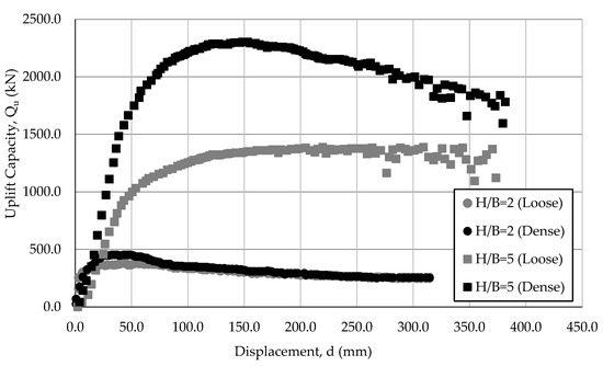
Figure 5.
Variation of Qu–d (no geogrid).
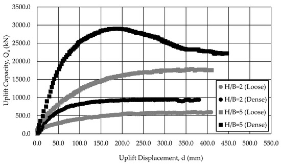
Figure 6.
Variation of Qu–d (geogrid inclined at 45°).
A dimensionless factor, the breakout factor, was used to compare the uplift capacities. The breakout factor, NUR, is expressed as:
where Qu is the uplift capacity, γ is the unit weight of the sand, Ab is the area of the anchor plate, and H is the embedment depth of the anchor. In the case of using geogrids oriented vertically downwards, the increase in the uplift capacity of the anchors shows an intermediate level increase compared to the unreinforced condition. When the geogrid configurations are compared, as seen in Figure 7, the best performance is obtained when the geogrid is used with a 45° inclination for the increases in uplift capacity both for soil densities and anchor embedment ratios. In all cases, the increase in improvement percentage decreases for deeper burial rates.
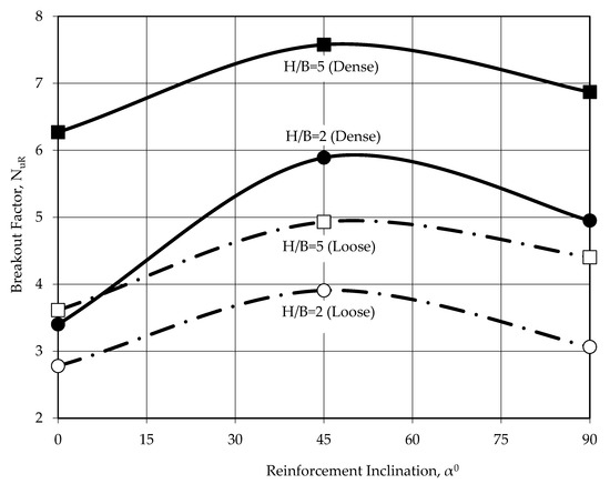
Figure 7.
Variation of NUR–α for geogrid reinforcement.
Figure 8 and Figure 9 show the variation of NUR with H/B for loose and dense sand conditions, respectively. From the Figures it is seen that the NUR values increase remarkably with burial depth and unit volume weight of the soil. The results obtained from centrifuge experiments were compared with the tests performed on unreinforced soils by Dickin [7], and as seen in Figure 8 and Figure 9. These results confirm the data of the strip anchor plates embedded in unreinforced sand obtained in this study. They also provide a sensitive lower bound on their uplift capacity for reinforced strip anchors in any direction. The comparison for results obtained for dense sand conditions is particularly consistent.
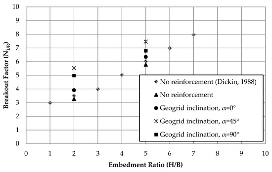
Figure 8.
Comparison of results with the literature [7] for dense sand.
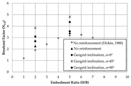
Figure 9.
Comparison of results with literature [7] for loose sand.
3. Finite Element Analysis
Experimental studies were modeled with using the finite element method (FEM), and the centrifuge test results were compared with the numerical results. The experiments were modeled with the PLAXIS 2D [27] program, which can reflect the plane strain problem. There are many soil models in the finite element programs, and it is aimed to fully reflect the elastoplastic behavior of the soil properties in the study. For this purpose, the Hardening Soil model (HSM), which is one of the advanced soil models, was used to reflect the elastoplastic behavior of the soil in numerical analysis. Soil properties obtained from laboratory tests are presented in Table 4.
Table 4.
Values of soil parameters used in FEM analyses.
In the numerical analysis, a rigid beam element of the strip anchor plate is modeled. The modulus of elasticity of the steel material was used as the stiffness values, EA and EI. Soil/structure interface behavior in PLAXIS can be modeled using parameters generated using the Rint interaction coefficient. In this study, fully rough interface conditions, Rint = 1 are assumed.
Numerical studies were carried out in three stages. In the first stage, the mesh effect was investigated and the mesh density to be used in the analysis was determined. In the second stage, the uplift capacity/displacement curves obtained from the experiments were compared, and in the last stage, the comparisons in terms of the breakout factor were presented collectively.
Investigation of Mesh Density on Results
The mesh density used in the FE program directly affects the results. There are five different mesh densities in the PLAXIS program, and the effects of five different mesh densities (very coarse, VC; coarse, C; medium, M; fine, F; and very fine, VF) on the results for the experimental model were examined before the analysis. For this purpose, the anchor plate at H/B = 5 burial depth was modeled, and the results were examined. Table 5 presents the mesh densities used in the analysis, the number of elements for these densities, and the ultimate uplift capacities obtained as a result of the analysis.
Table 5.
Effect of mesh coarseness.
FE models for very coarse and very fine mesh conditions for the H/B = 5 model are given in Figure 10 and Figure 11, respectively. The results obtained for different mesh ranges are presented in Figure 12, and fine mesh density, which did not affect the result, was used in the analysis.
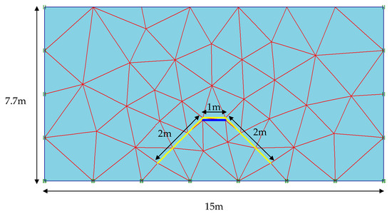
Figure 10.
Very coarse mesh and boundary conditions for a strip anchor (H/B = 5).
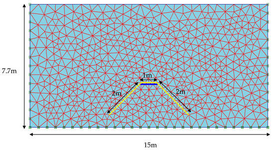
Figure 11.
Very fine mesh and boundary conditions for a strip anchor (H/B = 5).
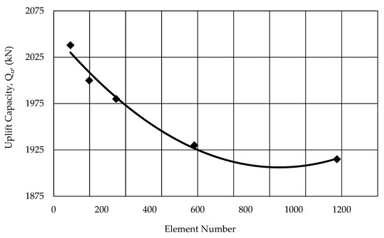
Figure 12.
Effect of mesh size (H/B = 5, dense sand).
4. Results and Discussion
4.1. Comparison between Numerical and Experimental Results
Experimental studies were modeled with the FE program, and the numerical and experimental results were compared. The uplift capacity/displacement curves were obtained and the compatibility between the results was examined. The uplift capacity/displacement curves obtained for H/B = 2 embedment ratio in typical unreinforced loose sand soil conditions are presented in Figure 13. For unreinforced sand, the uplift capacity value measured as a result of the centrifuge test is 381 kN, while the estimated uplift capacity value as a result of the finite element analysis is 374 kN. It was found that the values obtained as a result of numerical and experimental studies are in good agreement for all load/displacement curves. The results were also compared for the breakout factor.
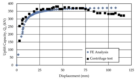
Figure 13.
Curves of uplift capacity/displacement behavior in unreinforced loose sand (H/B = 2).
4.2. Comparison between Breakout Factors
The results were evaluated in terms of the breakout factor (NUR), which is a dimensionless factor. The effect of geogrid layout (angle) for reinforced soils is presented in Figure 14 and Figure 15 for both soil densities. It shows that the most effective result is obtained when the geogrid is placed at an angle of 45° for loose and dense soil. It was observed that the value of the breakout factor increased with the increase of the embedment depth. Similarly, the increase in soil densities also increased the breakout factor value.
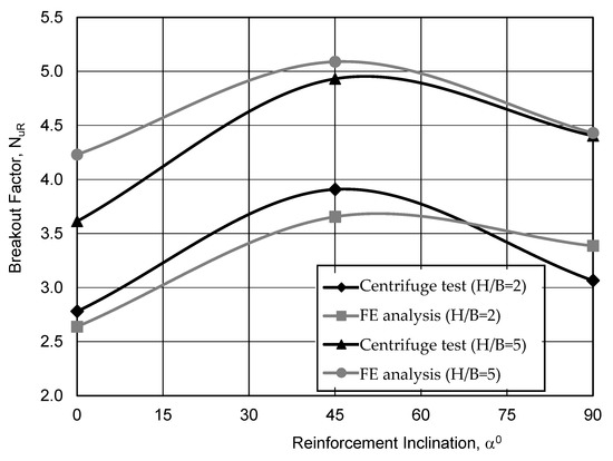
Figure 14.
Comparison of breakout factor with numerical and experimental results in reinforced loose sand.
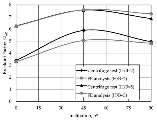
Figure 15.
Comparison of breakout factor with numerical and experimental results in reinforced dense sand.
5. Conclusions
The uplift capacity behavior of the strip anchor plates in reinforced and unreinforced sands was investigated using centrifuge model tests and a nonlinear finite element program. The main results of this study are summarized below.
- The uplift capacity of the anchors in the unreinforced soil is significantly affected by the embedment ratio and soil density. The uplift response tends to be brittle, particularly for anchor plates embedded in dense sand that show a significant post-peak reduction in uplift capacity.
- The uplift capacity is significantly improved when geogrid is used. In this study, up to 98% increases in uplift capacity were obtained with reinforcement. The use of the geogrid with an inclination angle of 45 degrees as the reinforcement configuration gave more effective results than the use of the geogrid horizontally and vertically.
- Finite element analyses were performed with hyperbolic soil models using parameters obtained from drained triaxial tests. The results obtained using the finite element method were found to be close to the results of centrifugal model tests. It was observed that the two parameters that significantly affect the uplift capacity of the strip anchor plates embedded in the unreinforced sand are the embedment ratio and the unit weight of the soil.
- The fact that the study was carried out with the centrifuge technique is thought to contribute to obtaining results closer to the actual uplift capacity values of the anchor plates. In addition, the study provides preliminary evidence that the uplift capacity of the anchor plates can be further improved by placing the geogrid layers at different angles.
- The experimental results presented in this study are not specific to a known field subsoil and are likely to be affected by the boundary conditions applied in the experimental study. However, it is thought that the test results are significant and determine the potential advantage of geogrid reinforcement of the sand on the uplift behavior of the anchor plates.
Author Contributions
Conceptualization, project administration, supervision: E.A.D.; methodology, data curation, software, validation, and formal analysis: S.B., M.L. and K.I.; writing—review and editing and writing—original draft: M.S.K. All authors have read and agreed to the published version of the manuscript.
Funding
This research received no external funding.
Institutional Review Board Statement
Not applicable.
Informed Consent Statement
Not applicable.
Data Availability Statement
Not applicable.
Conflicts of Interest
The authors declare no conflict of interest.
Abbreviations
| N | gravity acceleration factor |
| BP | width of the prototype anchor plate |
| BM | width of the model anchor plate |
| LP | length of the prototype anchor plate |
| LM | length of the model anchor plate |
| tP | thickness of the prototype anchor plate |
| tM | thickness of the model anchor plate |
| QUP | prototype uplift force |
| QUM | model uplift force |
References
- Choi, H.C.; Ji, K.; Kwon, K.; Kong, J.S. Sustainability of industrial building SSMR through experimental and analytical study under wind uplift load. Sustainability 2021, 13, 13815. [Google Scholar] [CrossRef]
- Cheng, P.; Guo, J.; Yao, K.; Liu, C.; Liu, X.; Liu, F. Uplift behavior of pipelines buried at various depths in spatially varying clayey seabed. Sustainability 2022, 14, 8139. [Google Scholar] [CrossRef]
- Jearsiripongkul, T.; Lai, V.Q.; Keawsawasvong, S.; Nguyen, T.S.; Van, C.N.; Thongchom, C.; Nuaklong, P. Prediction of uplift capacity of cylindrical caissons in anisotropic and inhomogeneous clays using multivariate adaptive regression splines. Sustainability 2022, 14, 4456. [Google Scholar] [CrossRef]
- Wang, Q.; Xiao, Z.; Zhao, X.; Feng, D. The effects and vertical bearing capacity of two jacked model piles in sand. Sustainability 2022, 14, 14493. [Google Scholar] [CrossRef]
- Dickin, E.A.; Leung, C.F. Centrifugal modeling of the behaviour of vertical anchor plates. J. Geotech. Eng. 1983, 109, 1503–1525. [Google Scholar] [CrossRef]
- Chattopadhyay, B.C.; Pise, P.J. Breakout resistance of horizontal anchors in sand. Soils Found. 1986, 26, 16–22. [Google Scholar] [CrossRef] [PubMed]
- Dickin, E.A. Uplift behaviour of horizontal anchor plates in sand. J. Geotech. Eng. 1988, 114, 1300–1317. [Google Scholar] [CrossRef]
- Frydman, S.; Shaham, I. Pullout capacity of slab anchors in sand. Can. Geotech. J. 1989, 26, 385–400. [Google Scholar] [CrossRef]
- Dickin, E.A.; Leung, C.F. Performance of piles with enlarged bases subjected to uplift forces. Can. Geotech. J. 1990, 27, 546–556. [Google Scholar] [CrossRef]
- Dickin, E.A.; Leung, C.F. The influence of foundation geometry on the uplift behaviour of piles with enlarged bases in sand. Can. Geotech. J. 1992, 29, 498–505. [Google Scholar] [CrossRef]
- Ghaly, A.M.; Clemence, S.P. Pullout performance of inclined helical screw anchors in sand. J. Geotech. Geoenviron. Eng. 1998, 124, 617–627. [Google Scholar] [CrossRef]
- Dickin, E.A.; Laman, M. Uplift response of strip anchors in cohesionless soil. Adv. Eng. Software 2007, 38, 618–625. [Google Scholar] [CrossRef]
- Bildik, S.; Laman, M. Experimental investigations on uplift behaviour of plate anchors in cohesionless soil. J. Fac. Eng. Archit. Gazi Univ. 2011, 26, 486–496. [Google Scholar]
- Wang, D.; Hu, Y.; Randolph, M.F. Keying of rectangular plate anchors in normally consolidated clays. J. Geotech. Geoenviron. Eng. 2011, 137, 1244–1253. [Google Scholar] [CrossRef]
- Bera, A.K. Parametric study on uplift capacity of anchor with tie in sand. KSCE J. Civ. Eng. 2014, 18, 1028–1035. [Google Scholar] [CrossRef]
- Niroumand, H.; Kassim, K.A. Uplift response of circular plates as symmetrical anchor plates in loose sand. Geomech. Eng. 2014, 6, 321–340. [Google Scholar] [CrossRef]
- Niroumand, H.; Kassim, K.A. Experimental and numerical modeling of uplift behavior of rectangular plates in cohesionless soil. Geomech. Eng. 2014, 6, 341–358. [Google Scholar] [CrossRef]
- Zhu, H.H.; Mei, G.X.; Xu, M.; Liu, Y.; Yin, J.H. Experimental and numerical investigation of uplift behavior of umbrella-shaped ground anchor. Geomech. Eng. 2014, 7, 165–181. [Google Scholar] [CrossRef]
- Schiavon, J.A.; Tsuha, C.H.C.; Neel, A.; Thorel, L. Physical modelling of a single-helix anchor in sand under cyclic loading. In Proceedings of the 3rd European Conference on Physical Modelling in Geotechnics, Nantes, France, 1–3 June 2016; pp. 1–3. [Google Scholar]
- Krishnaswamy, N.R.; Parashar, S.P. Uplift behaviour of plate anchors with geosynthetics. Geotext. Geomembr. 1994, 13, 67–89. [Google Scholar] [CrossRef]
- Ilamparuthi, K.; Dickin, E.A. The influence of soil reinforcement on the uplift behaviour of belled piles embedded in sand. Geotext. Geomembr. 2001, 19, 1–22. [Google Scholar] [CrossRef]
- Ilamparuthi, K.; Dickin, E.A. Predictions of the uplift capacity of belled piles in geogrid cell reinforced sand. Geotext. Geomembr. 2001, 19, 89–109. [Google Scholar] [CrossRef]
- Niroumand, H.; Kassim, K.A.; Nazir, R. The influence of soil reinforcement on the uplift response of symmetrical anchor plate embedded in sand. Measurement 2013, 46, 2608–2629. [Google Scholar] [CrossRef]
- Keskin, M.S. Model studies of uplift capacity behavior of square plate anchors in geogrid-reinforced sand. Geomech. Eng. 2015, 8, 595–613. [Google Scholar] [CrossRef]
- Choudhary, A.K.; Pandit, B.; Babu, G.S. Uplift capacity of horizontal anchor plate in geocell reinforced sand. Geotext. Geomembr. 2019, 47, 203–216. [Google Scholar] [CrossRef]
- Dickin, E.A.; King, G.J.W. Numerical modelling of the load-displacement behaviour of anchor walls. Comput. Struct. 1997, 63, 849–858. [Google Scholar] [CrossRef]
- PLAXIS. User Manual, 2D Version 8; Brinkgreeve, R.J.B., Ed.; Delft University of Technology & PLAXIS b.v.: Delft, The Netherlands, 2002. [Google Scholar]
Disclaimer/Publisher’s Note: The statements, opinions and data contained in all publications are solely those of the individual author(s) and contributor(s) and not of MDPI and/or the editor(s). MDPI and/or the editor(s) disclaim responsibility for any injury to people or property resulting from any ideas, methods, instructions or products referred to in the content. |
© 2023 by the authors. Licensee MDPI, Basel, Switzerland. This article is an open access article distributed under the terms and conditions of the Creative Commons Attribution (CC BY) license (https://creativecommons.org/licenses/by/4.0/).