Abstract
In this paper, the head stabilization problem of the snake robot in planar motion is studied. When the snake robot performs a planar movement with an inchworm locomotion gait, the head controller of the snake robot swings up and down due to a fluctuation in the joint angle of the neck joint. However, the snake robot usually has a laser radar and other visual instruments on the head, and the swing of the head causes the visual instrument to fail to obtain external visual information normally, which affects the navigation and detection of the snake robot. In this paper, a head stabilization method for a snake robot in planar motion is proposed. The inertial sensor is used to obtain the direction parameters to control the swing of the head when the snake robot moves, and the effectiveness of the method is verified by a simulation and an experiment of the real robot.
1. Introduction
A snake robot has a relatively unique movement mode, and it moves with the friction force between itself and the ground as power. Due to its high degree of freedom (DOF), snake robots have high flexibility. Equipped with cameras, sensors and other equipment, snake robots can complete corresponding tasks on various complex terrains [1]. Snake robots can carry out search and rescue work in the ruins of a disaster area [2]; they can perform search work in narrow spaces [3]; they can complete a fire-fighting task at a dangerous fire scene [4]; due to the slender external structure of snake robots [5], they can complete an exploration operation underground or in a pipeline [6]; they can replace humans in an environment full of poisonous gas and other dangerous areas to complete investigations; they can complete tasks such as investigation, assassination and blasting on dangerous battlefields due to their relatively concealed movements; and in the direction of aerospace, they can replace ordinary robots to complete tasks such as detection and sampling, and other tasks in complex and unknown environments, and can also perform maintenance on a space station. In addition, snake robots can be used in the medical field [7]. Since snake robots are slender overall, their control method in the elastic variable channel can be used to promote the multi-directional development of medical endoscopes. Due to the various advantages of snake robots, they are full of research value.
Snake robots with visual sensors such as cameras or lidars can detect and navigate in some unknown environments [8]. However, due to the movement characteristics of the snake robot, its head bobs when it is moving, which causes the head vision sensor to fail to obtain external visual information normally and affects the robot’s navigation. Therefore, the study of the head stabilization of snake robots in planar motion is an important research topic.
Carnegie Mellon University used the mode decomposition method to keep the head of the snake robot in the same direction during the rolling gait [9]. This method can ensure that the head camera of the snake robot works normally during the rolling gait. H. Yamada et al. stabilized the head of the snake robot by controlling the motion of its neck [10]. However, when the method is converted from a continuous model to a discrete model, it causes the head position to move forward and backward, and the control of the robot is impacted. Z. Bing compensated for the head offset angle of the snake robot by calculating the derivative of the snake curve with respect to time [11]. Wu et al. introduced a virtual joint as the desired direction and analyzed the joint angle relationship between the virtual joint and the first two joints of the head in HNC (head navigation control) [12]. However, this lacks validation on the effect of head navigation, and it is difficult to tune parameters using a cyclic inhibition model. G. Qiao et al. achieved partial control and proposed to divide the snake robot into different parts such as the head, neck and torso. The torso is used to push the snake robot forward, while the neck and head are used to control the snake robot’s direction [13]. However, this method needs to treat multiple modules as the neck part, so the number of joints increases, which is difficult to apply to the CPG model based on curvature control. G. Dao et al. described the direction of motion with a virtual coordinate system model, and studied HNC using the Kuramoto oscillator model based on a single-chain bidirectional coupling network [14]. Based on a CPG network [15], X. Wu et al. used virtual joints to stabilize the head. Although this solution can effectively ensure the head stabilization of a snake robot [16], it lacks the feedback of head position information, and the efficiency is not high. The authors of [17] used the main ailerons and the tail elevators to counteract the pitch angle.
The above strategies for head stabilization of wheeled snake robots are divided into the following two types. The first type is to place the head of the snake robot into a snake curve and compensate for the head direction by calculating the snake curve; the other type is to introduce virtual joints and calculate the virtual joint angles by using the trunk joint angles, thereby controlling the neck joints to keep the head stable. These two types of methods need to obtain the compensation angle of the head stabilization by calculating the joint angle or the snake curve. Compared with directly obtaining the compensation angle, these methods have large errors, and the above methods are not suitable for non-wheeled snake robots. In the inchworm locomotion gait [18,19], since the serpentine curve of the inchworm locomotion gait is affected by its own gravity, the calculation of the serpentine curve and the virtual joint angle produces errors. This paper proposes a non-wheeled snake robot head stabilization compensation strategy based on an inertial sensor (IMU) [20]. The head controller is fed back the direction data by the sensor, and the head controller is stabilized by head joint compensation. In this paper, the scheme is analyzed theoretically, and the method is verified by simulation and experiment.
The reminder of this paper is organized as follows: In Section 2, we introduce the previous work. In Section 3, we analyze the head stabilization of a snake robot. In Section 4, we validate the head stabilization strategy for the snake robot through simulations. In Section 5, we further validate the head stabilization algorithm through experiments on the snake robot. In Section 6, we conduct an analysis and discussion of the results from the experiments and simulations, and finally, the conclusion of this paper is discussed in Section 7.
2. Previous Related Work
This section introduces some of our previous work on snake robots. We developed a non-wheeled snake robot with 16 DOF. The robot consists of 16 modular joints, a head module and a tail battery module. The robot is shown in Figure 1. The joint modules of the snake-like robot are orthogonally connected and can perform three-dimensional movements in space. The tail battery module is responsible for powering the snake-like robot. The head module contains a head controller, inertial sensors, a laser rangefinder and other devices. The head controller of the snake-like robot is a computing stick responsible for processing sensor information and overall motion planning of the robot. Relevant work is described in [21].
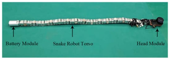
Figure 1.
Snake robot integration.
The dynamic equation of the snake robot can be represented as follows [21]:
In Equation (1), represents the mass matrix, represents the matrix of centrifugal and Coriolis torques, represents the friction matrix and represents the gravity matrix.
The control law for the snake robot can be represented as follows:
where represents the desired joint matrix, represents the tracking error, and are positive definite matrices to ensure stability. The specific control block diagram is shown in Figure 2.
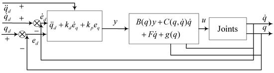
Figure 2.
Schematic diagram of inverse dynamics control [21].
3. Head Stabilization Strategy Analysis
The specific work on the dynamics and control laws of snake-like robots is detailed in [21].
To ensure the stable operation of the head of snake robot, the first joint (pitch direction) needs to be planned and controlled separately. Head stabilization requires the first joint to meet the following conditions [12]:
- The direction of the head module is consistent with the direction of movement;
- The first joint angle frequency is consistent with other joint angle frequencies;
- The period of the first joint is the same as that of other joints, but the phase and amplitude are different.
In Figure 3, 1, 2 and 3 represent the first three links of the robot, represents the original joint angle of the first joint, represents the joint angle of the second joint and represents the joint angle of the head joint. It can be seen from the figure that and have the same phase and frequency but different amplitudes. Set the original joint angle of the first joint as , and the phase difference of adjacent joints as , the ideal angle equation can be expressed as (3).
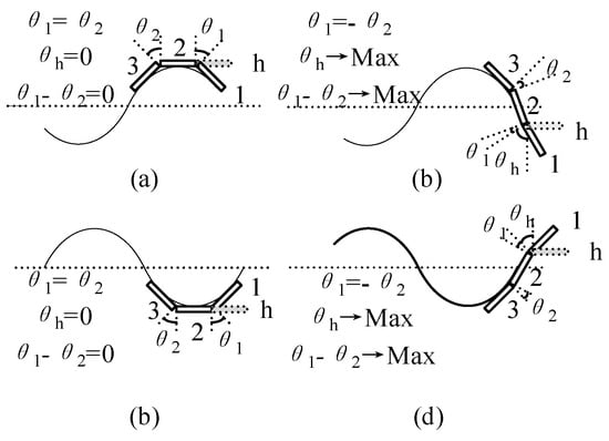
Figure 3.
(a–d) Four typical cases of head navigation motion.
From (3), it can be seen that the main problem of controlling the head direction has been changed to solving the value of the front amplitude coefficient. Add a virtual angle that is out of phase with the first joint the same as that of the first and second joints. Taking this virtual joint as a reference, the crossing time of and can be calculated. At the same time, since is equal to at this time, the value of the amplitude coefficient can be obtained through (4).
Add a virtual CPG signal in the CPG network to calculate the head navigation angle, as shown in Figure 4. According to (3), the correction signal is of the head joint, the head in the head navigation motion is calculated by the output of the first CPG (, 1) and the second CPG (, 2). The final calculation model is:
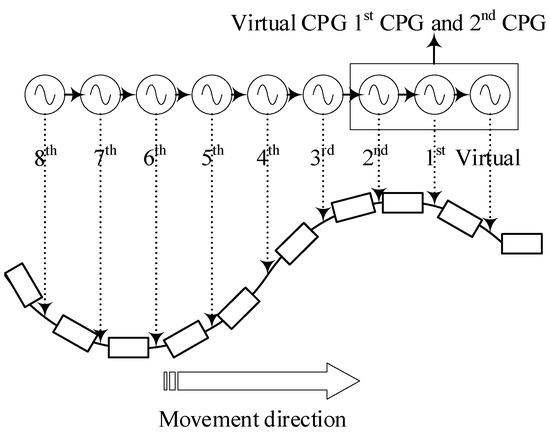
Figure 4.
CPG network for controlling head navigation motion.
Through the above methods, the ideal direction of the head can be obtained indirectly, and the head can be stabilized when wheeled snake robot is in a serpentine gait. However, in the actual application process, due to the lack of sideslip constraints [22], the planar movement of non-wheeled snake robots cannot perform serpentine gaits [23]. The direction of movement is parallel to the ground, which is the horizontal direction.
Among them, represents the movement direction of snake robot, and is the direction of the horizontal plane. The head pose of snake robot is shown in Figure 5. With the help of IMU inertial sensor, it is relatively easy to obtain the real-time direction and horizontal offset angle of the head joint, namely
and head stabilization can be facilitated with the aid of measurement information.
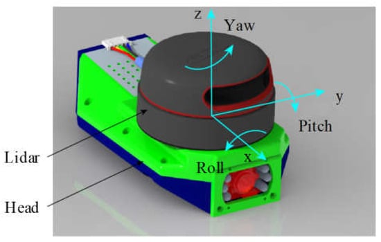
Figure 5.
Schematic diagram of snake robot head pose.
In Figure 6, 1 represents the connecting rod where the head module is located, 2 and 3 represent the second and third links of the robot, respectively and h represents the horizontal direction. When the head module deviates from the horizontal direction, the inertial sensor IMU obtains the vertical offset angle θ of the head joint and performs real-time compensation through the neck joint angle to restore the head joint to the horizontal direction.
where and are PD control parameters [24]. Through the above control method, the stable control of snake head is realized. Since IMU can measure the direction of the head module in real time, eliminating the error obtained from the calculation of the neck joint angle, the accuracy of the vertical offset angle of the head obtained in real time is higher, and the head will be more stable.
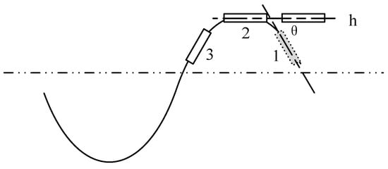
Figure 6.
Schematic diagram of the head stabilization strategy.
4. Head Stabilization Simulation
In this paper, we use ROS GAZEBO to simulate the head stabilization of the snake robot. Figure 7 shows the simulation model established in gazebo. The simulation model basically restores the real snake robot, equipped with a 360° laser radar, IMU inertial sensor and other equipment.
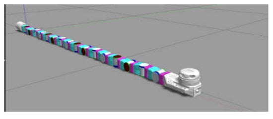
Figure 7.
Snake robot simulation model.
In this article, we made improvements to the CPG model in Figure 4, as shown in Figure 8. We divided the robot into two parts: the head and the torso. The head of the snake robot consisted of the head module and the first joint of the robot body; the torso of the snake robot consisted of the remaining 15 joints and the battery module. In the improved CPG model, the data obtained from the IMU for the head joint are used for feedback, which is controlled through the head controller.
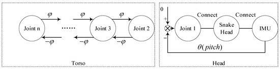
Figure 8.
CPG network for controlling head navigation motion by IMU.
In Gazebo, given the inchworm locomotion gait of a snake robot [25,26], the inchworm locomotion gait equation is:
On the basis of the inchworm locomotion gait, the joint angle of the neck joint of the snake robot is compensated by Formula (8). The simulation process is shown in Figure 9 and Figure 10. Figure 9 represents the simulation without the stable algorithm, while Figure 10 represents the simulation with the stable algorithm. The simulation results are shown in Figure 11.
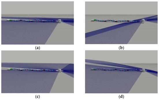
Figure 9.
Head stabilization simulation without stabilization algorithm. (a) Phase is 0; (b) phase is π/2; (c) phase is π; (d) phase is 3 π/2.
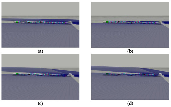
Figure 10.
Head stabilization simulation with stabilization algorithm. (a) Phase is 0; (b) phase is π/2; (c) phase is π; (d) phase is 3 π/2.
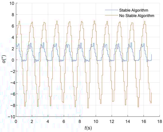
Figure 11.
Head stabilization simulation data.
In Figure 11, α represents the vertical component of the head module of the snake robot, represents time, the red curve represents the vertical component of the head module without a stabilization algorithm and the blue curve represents the vertical direction of the head module when the stabilization algorithm is the added portion. It can be seen that the stabilization effect of the stabilization algorithm is relatively good.
5. Head Stabilization Experiment
It can be seen from the simulation experiment that the stabilization algorithm can effectively help the head of the snake robot to stabilize. On this basis, the head stabilization experiment of the real snake robot is carried out to verify the head stabilization effect.
This experiment is carried out with a 16-DOF snake robot [21] with a head controller and a battery module. The ground uses rubber as the playground for the snake robot to increase static friction to ensure the operating efficiency of the snake robot. The experimental scene is shown in Figure 12.
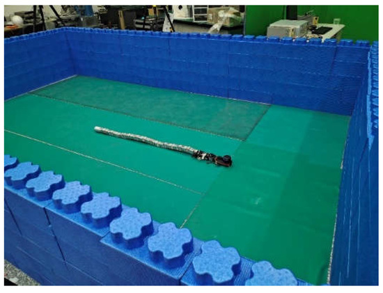
Figure 12.
Experimental Scene.
The experiment uses the motion capture system VICON to verify the head stabilization control. The head posture change of the snake robot is tracked through the pose of VICON’s marker point coordinate system in the VICON coordinate system to verify the effect of head stabilization control. The experiment mainly involves the VICON coordinate system {Ov:xv,yv,zv}, the head coordinate system {Oh:xh,yh,zhsss} and the marker coordinate system {Om:xm,ym,zm}. The following relationship is observed between the attitudes of the coordinate systems:
Among them, , and , respectively, represent the attitude rotation matrix of the head coordinate system relative to the VICON coordinate system, the marker coordinate system relative to the VICON coordinate system and the head coordinate system relative to the marker coordinate system. To simplify the calculation, the head coordinate system coincides with the marker point coordinate system during the experiment, as shown in Figure 13.
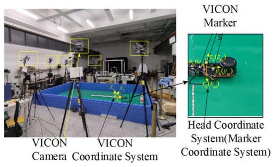
Figure 13.
VICON system and coordinate system definition.
Based on the robot’s inchworm locomotion gait, experiments were carried out on the movement of the snake robot with and without the stabilization algorithm. The experimental procedure is shown in Figure 14 and Figure 15 and the experimental results are shown in Figure 16.
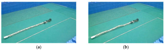
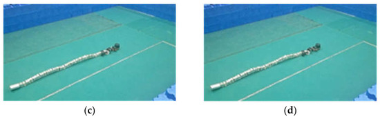
Figure 14.
Head stabilization experiment without stabilization algorithm. (a) Phase is 0; (b) phase is π/2; (c) phase is π; (d) phase is 3 π/2.
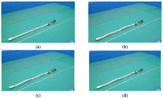
Figure 15.
Head stabilization experiment with stabilization algorithm. (a) Phase is 0; (b) phase is π/2; (c) phase is π; (d) phase is 3 π/2.
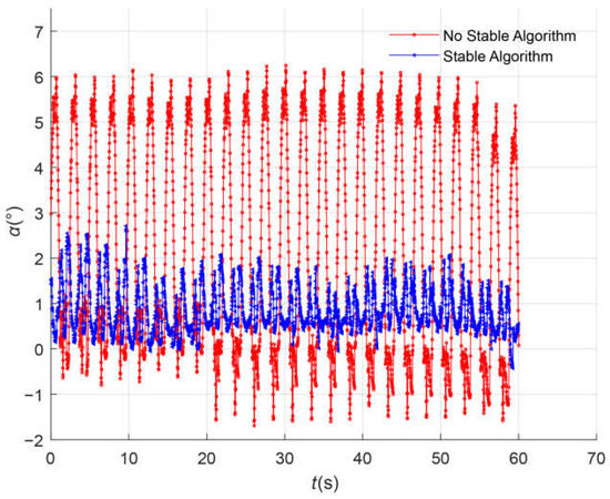
Figure 16.
Head stabilization experimental data.
From Figure 14 and Figure 15, it can be seen that when the stable algorithm is not applied, the swing amplitude of the robot’s head is larger, while under the stable algorithm, the swing amplitude of the robot’s head is significantly reduced.
Through experimental data, it can be seen that the compensation algorithm can effectively help the head controller of the snake robot to stabilize, thereby helping the laser radar to work stably.
6. Discussion
The simulation and experimental data are analyzed in the following.
Figure 17 is the comparison of the head pitch angle with and without the stable algorithm in the simulation and experimental environments. By calculating the peaks and troughs of the curve, the average value of the peaks without the stable algorithm under the simulation is shown to be 6.74°, and the average value of the troughs is −7.98°. The average value of the peaks with the stable algorithm under the simulation is 2.86°, and the average value of the troughs is −0.30°. By calculation, the reduction ratio of the head stabilization amplitude in the simulation environment is shown to be 21.47%. The average value of the peaks without the stable algorithm under the experiment is 6.13°, the average value of the troughs is −1.57°, the average value of the peaks with the stable algorithm under the experiment is 1.77°, and the average value of the troughs is 0.08°. By calculation, the reduction ratio of the head stabilization amplitude in the experimental environment is shown to be 22.08%.
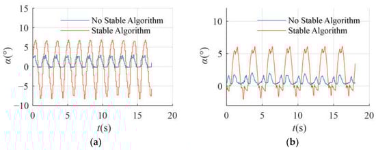
Figure 17.
Comparing with and without stable algorithm under simulation and experiment. (a) Head pitch angle with and without stabilization algorithm under simulation; (b) head pitch angle with and without stabilization algorithm under experiment.
In Figure 17a, the Root Mean Square Error (RMSE) of the simulation without the stability algorithm is 5.10, and the RMSE of the simulation with the stability algorithm is 1.57; the RMSE between the simulations with and without the stable algorithm is 4.42. In Figure 17b, the RMSE of the experiment without the stability algorithm is 3.23, and the RMSE of the experiment with the stability algorithm is 0.94; the RMSE between the simulations with and without the stable algorithm is 2.68.
According to the calculation results, the head stabilization efficiency of the snake robot in this scheme is high, which can effectively restrain the head fluctuation and ensure the stabilization of its head.
As can be seen from Figure 18, the stabilized joint angle under the simulation is approximately 0° to 3°, and the stabilized joint angle under the experiment is approximately 0° to 2°; this is because the head of the snake robot is affected by its own gravity. When the head of the snake robot bobs upwards, due to the influence of gravity and the compensation algorithm, the upward swing of the head is very small, almost zero. Therefore, in the simulation and the experiment with the stable algorithm, the joint angle is basically above 0°. In Figure 18a, the RMSE between the simulations and experiments without the stable algorithm is 13.57, while the RMSE between the simulations and experiments with the stable algorithm is 2.07 as shown in Figure 18b. It can be seen that after adding the stability algorithm, the simulation and experimental data are significantly closer, both converging towards 0°.
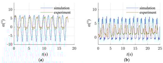
Figure 18.
Comparison of simulation and experimental data. (a) Pitch angle of head module without stabilization algorithm; (b) pitch angle of head module with stabilization algorithm.
In Figure 18, the pitch angle of the head module under the experiment is smaller than that of the simulation. This is due to the limitation of the material of the head module of the snake robot. When the snake robot performs an inchworm gait movement, the head module is affected by other joints to swing up and down, and due to the low rigidity of the head module material, it is difficult to achieve the predetermined joint angle, so the overall pitch angle of the head module under the experiment is smaller than the simulation data, especially when the head of the snake robot bobs upwards. Since the snake is affected by the gravity of its head and its own material, it is difficult for the head of the snake robot to bob upwards, so the head direction angle under the experiment is basically above 0°.
7. Conclusions
Aimed at solving the problem that the traditional head stabilization method for non-wheeled snake robots has large errors when the snake robot moves in the plane, a method based on inertial sensor feedback compensation is proposed for the non-wheeled snake robot with an inchworm locomotion gait. The stabilization control of the head controller is carried out, and it is verified by a simulation and an experiment. In the simulation, the pitch angle amplitude of the head of the snake robot under the stabilization algorithm is reduced by a ratio of 21.47%, and the ratio in the experiment is 22.08%. The results show that this method can effectively improve the head stabilization of the non-wheeled snake robot with an inchworm locomotion gait.
Author Contributions
Data curation, Q.W.; resources, Z.X.; supervision, Y.S.; writing—original draft, L.B. All authors have read and agreed to the published version of the manuscript.
Funding
This research was funded by National Natural Science Foundation of China (51805107) and the China Postdoctoral Science Foundation funded project (2018M641818, 2021T140159).
Conflicts of Interest
The authors declare no conflict of interest.
References
- Baysal, Y.A.; Altas, I.H. Adaptive Snake Robot Locomotion in Different Environments. In Proceedings of the 2020 International Conference on Control, Automation and Diagnosis (ICCAD), Paris, France, 7–9 October 2020; pp. 1–6. [Google Scholar]
- Yang, W.; Wang, G.; Shen, Y. Perception-Aware Path Finding and Following of Snake Robot in Unknown Environment. In Proceedings of the 2020 IEEE/RSJ International Conference on Intelligent Robots and Systems (IROS), Las Vegas, NV, USA, 24 October 2020–24 January 2021; pp. 5925–5930. [Google Scholar]
- Han, S.; Chon, S.; Kim, J.; Seo, J.; Shin, D.G.; Park, S.; Kim, J.T.; Kim, J.; Jin, M.; Cho, J. Snake Robot Gripper Module for Search and Rescue in Narrow Spaces. IEEE Robot. Autom. Lett. 2022, 7, 1667–1673. [Google Scholar] [CrossRef]
- Liljebäck, P. Snake Robots: Modelling, Mechatronics, and Control; Springer: Berlin/Heidelberg, Germany, 2013. [Google Scholar]
- Toyoshima, S.; Matsuno, F. A study on sinus-lifting motion of a snake robot with energetic efficiency. In Proceedings of the 2012 IEEE International Conference on Robotics and Automation, Saint Paul, MN, USA, 14–18 May 2012; pp. 2673–2678. [Google Scholar]
- Prada, E.; Valasek, M.; Virgala, I.; Gmiterko, A.; Kelemen, M.; Hagara, M.; Liptak, T. New approach of fixation possibilities investigation for snake robot in the pipe. In Proceedings of the 2015 IEEE International Conference on Mechatronics and Automation (ICMA), Beijing, China, 2–5 August 2015; pp. 1204–1210. [Google Scholar]
- Wang, C.; Puranam, V.R.; Misra, S.; Venkiteswaran, V.K. A Snake-Inspired Multi-Segmented Magnetic Soft Robot Towards Medical Applications. IEEE Robot. Autom. Lett. 2022, 7, 5795–5802. [Google Scholar] [CrossRef]
- Wang, G.; Yang, W.; Shen, Y.; Shao, H.; Wang, C. Adaptive Path Following of Underactuated Snake Robot on Unknown and Varied Frictions Ground: Theory and Validations. IEEE Robot. Autom. Lett. 2018, 3, 4273–4280. [Google Scholar] [CrossRef]
- Gong, C.; Travers, M.; Astley, H.C.; Goldman, D.I.; Choset, H. Limbless locomotors that turn in place. In Proceedings of the 2015 IEEE International Conference on Robotics and Automation (ICRA), Seattle, WA, USA, 25–30 May 2015; pp. 3747–3754. [Google Scholar]
- Yamada, H.; Mori, M.; Hirose, S. Stabilization of the head of an undulating snake-like robot. In Proceedings of the 2007 IEEE/RSJ International Conference on Intelligent Robots and Systems, San Diego, CA, USA, 29 October 2007–2 November 2007; pp. 3566–3571. [Google Scholar]
- Bing, Z.; Cheng, L.; Huang, K.; Jiang, Z.; Chen, G.; Rohrbein, F.; Knoll, A. Towards autonomous locomotion: Slithering gait design of a snake-like robot for target observation and tracking. In Proceedings of the 2017 IEEE/RSJ International Conference on Intelligent Robots and Systems (IROS), Vancouver, BC, Canada, 24–28 September 2017; pp. 2698–2703. [Google Scholar]
- Wu, X.; Ma, S. Neurally Controlled Steering for Collision-Free Behavior of a Snake Robot. IEEE Trans. Control. Syst. Technol. 2013, 21, 2443–2449. [Google Scholar] [CrossRef]
- Qiao, G.; Song, G.; Zhang, Y.; Zhang, J.; Li, Y. Head stabilization control for snake-like robots during lateral undulating locomotion. In Proceedings of the 2014 IEEE International Conference on Robotics and Biomimetics (ROBIO 2014), Bali, Indonesia, 5–10 December 2014; pp. 392–397. [Google Scholar]
- Dao, Q.M.; Vo, Q.T. Design of a CPG-based close-loop direction control system for lateral undulation gait of snake-like robots. In Proceedings of the 2017 International Conference on Advanced Technologies for Communications (ATC), Quy Nhon, Vietnam, 18–20 October 2017; pp. 114–119. [Google Scholar]
- Nor, N.M.; Ma, S. CPG-based locomotion control of a snake-like robot for obstacle avoidance. In Proceedings of the 2014 IEEE International Conference on Robotics and Automation (ICRA), Hong Kong, China, 31 May 2014–7 June 2014; pp. 347–352. [Google Scholar]
- Wu, X.; Ma, S. Head-navigated locomotion of a snake-like robot for its autonomous obstacle avoidance. In Proceedings of the 2010 IEEE/RSJ International Conference on Intelligent Robots and Systems, Taipei, Taiwan, 18–22 October 2010; pp. 401–406. [Google Scholar]
- Muscat, M.; Cammarata, A.; Maddio, P.D.; Sinatra, R. Design and development of a towfish to monitor marine pollution. Euro-Mediterr. J. Environ. Integr. 2018, 3, 11. [Google Scholar] [CrossRef]
- Hirose, S.; Mori, M. Biologically Inspired Snake-like Robots. In Proceedings of the 2004 IEEE International Conference on Robotics and Biomimetics, Shenyang, China, 22–26 August 2004; pp. 1–7. [Google Scholar]
- Serrano, M.M.; Chang, A.H.; Zhang, G.; Vela, P.A. Incorporating frictional anisotropy in the design of a robotic snake through the exploitation of scales. In Proceedings of the 2015 IEEE International Conference on Robotics and Automation (ICRA), Seattle, WA, USA, 25–30 May 2015; pp. 3729–3734. [Google Scholar]
- Tang, S.; Yang, W.; Bajenov, A.; Shen, Y. Inertial-Measurement-Unit (IMU) Based Motion Tracking for Biomorphic Hyper-Redundant Snake Robot. In Proceedings of the 2017 IEEE 7th Annual International Conference on CYBER Technology in Automation, Control, and Intelligent Systems (CYBER), Honolulu, HI, USA, 31 July 2017–4 August 2017; pp. 1124–1129. [Google Scholar]
- Ni, F.; Li, Y.; Zhou, Y.; Zhao, L.; Liu, H. Design of a Hierarchical Control System for Tetherless Snake Robot. In Proceedings of the 2019 IEEE International Conference on Mechatronics and Automation (ICMA), Tianjin, China, 4–7 August 2019; pp. 1254–1259. [Google Scholar]
- Tanaka, M.; Matsuno, F. Modeling and Control of Head Raising Snake Robots by Using Kinematic Redundancy. J. Intell. Robot. Syst. 2014, 75, 53–69. [Google Scholar] [CrossRef]
- Prautsch, P.; Mita, T. Control and analysis of the gait of snake robots. In Proceedings of the 1999 IEEE International Conference on Control Applications (Cat. No.99CH36328), Kohala Coast, HI, USA, 22–27 August 1999; Volume 1, pp. 502–507. [Google Scholar]
- Tomei, P. A simple PD controller for robots with elastic joints. IEEE Trans. Autom. Control 1991, 36, 1208–1213. [Google Scholar] [CrossRef]
- Han, S.; Wang, B.; Du, R. Design and Motion of a Redundant Snake Robot. In Proceedings of the 2010 International Conference on Measuring Technology and Mechatronics Automation, Changsha, China, 13–14 March 2010; pp. 962–965. [Google Scholar]
- Seeja, G.; Doss, A.S.A.; Hency, V.B. A Survey on Snake Robot Locomotion. IEEE Access 2022, 10, 112100–112116. [Google Scholar] [CrossRef]


Disclaimer/Publisher’s Note: The statements, opinions and data contained in all publications are solely those of the individual author(s) and contributor(s) and not of MDPI and/or the editor(s). MDPI and/or the editor(s) disclaim responsibility for any injury to people or property resulting from any ideas, methods, instructions or products referred to in the content. |
© 2023 by the authors. Licensee MDPI, Basel, Switzerland. This article is an open access article distributed under the terms and conditions of the Creative Commons Attribution (CC BY) license (https://creativecommons.org/licenses/by/4.0/).