Communication

A Method Based on Blackbody to Estimate Actual Radiation of Measured Cooperative Target Using an Infrared Thermal Imager

1
Changchun Institute of Optics, Fine Mechanics and Physics, Chinese Academy of Sciences, Changchun 130033, China
2
Agricultural Hyperspectral Application & Information Database, Changchun 130033, China
3
Key Laboratory of Airborne Optical Imaging and Measurement, Changchun Institute of Optics, Fine Mechanics and Physics, Chinese Academy of Sciences, Changchun 130033, China
*
Author to whom correspondence should be addressed.
Appl. Sci. 2023, 13(8), 4832; https://doi.org/10.3390/app13084832
Submission received: 5 February 2023 / Revised: 17 March 2023 / Accepted: 28 March 2023 / Published: 12 April 2023
(This article belongs to the Special Issue Recent Advances in Robotics and Intelligent Robots Applications)

Abstract

:
Infrared signature of targets is one important approach for target detection and recognition. When measuring the infrared signature of a target in the atmosphere, it is necessary to take the atmospheric transmittance and atmospheric radiation between the measured target and the observer into account. In this study, a blackbody-based approach for estimating atmospheric transmittance and atmospheric radiation is proposed to improve accuracy. Radiometric calibration is first carried out in the laboratory for the infrared thermal imager to determine the slope and offset used in the linear regression. With a set of different temperatures, radiance of the blackbody and digital number value of images are calculated. Finally, according to the analytical expressions derived, the atmospheric transmittance and atmospheric radiation are determined, and actual radiance for the cooperative target is calculated. Results demonstrate that the uncertainty of the actual radiance of measured cooperative target calculated via the proposed method is lower than that by MODTRAN, from MODTRAN at 5.7% and 16.7%, from proposed method at 2.56% and 10.2% in two experiments.

1. Introduction

With the further development of infrared focal plane arrays (IRFPA), infrared remote sensing techniques play an important role in many fields, especially in multiple military cases for aerospace vehicles [1,2,3,4]. Infrared signature has been demonstrated much during the last few years in feature acquisition and recognition of targets, which can provide signature information of targets such as radiance and intensity [5,6,7], for different vehicles usually represent different infrared signature.
At present, the research on the infrared radiation characteristics of targets mainly includes two ways, namely the simulation and the experiment. In the simulation, the mathematical radiation model is first established based on the state and the environment of targets. Then, according to the radiation formation mechanism of targets, each component that influences the radiation characteristic of the target is analyzed and calculated theoretically [8,9,10,11,12,13]. Although the simulation is widely used in the study of the infrared characteristics, due to the fact that they are not subject to the site and cost, the accuracy and effectiveness cannot be easily verified. In contrast, the experiment that measures and inverses the actual radiation of the target with a radiometrically calibrated infrared measuring system is the direct and the only means to obtain and verify the radiation characteristics of the measured target [14,15]. In experiments, infrared signature measurement of targets usually consists of three steps: (1) radiometric calibration for the infrared thermal imager, which aims at quantifying the relationship between the radiation received and the output digital number (DN); (2) estimation of the emission and reflection from the ground and the atmospheric effects, such as atmospheric transmittance and path radiation, which can be predicted by software like MODTRAN; (3) inversion of the radiation characteristics using a model of radiation measurement, according to the target material surface emissivity, transmittance and so on. In both approaches mentioned above, the influence caused by the atmosphere must be inevitably corrected, especially for long range targets. However, the estimation of atmospheric parameters and the atmospheric radiation, nowadays, mainly depends on atmospheric transmission radiative transfer software such as LOWTRAN, MODTRAN, and FASCODE, of which the uncertainty is merely approximately 20–30% which is far from enough in engineering application.
In this work, a method of infrared radiation measurement based on blackbody or an object served as a blackbody for cooperative targets is proposed, based on which the atmospheric transmittance and the atmospheric radiation are estimated and the actual radiation of the measured cooperative target is calculated with lower uncertainty. The proposed method can be considered as an alternative for practical scenes when measuring cooperative targets in engineering applications.

2. Materials and Methods

2.1. MODTRAN

Moderate Resolution Atmospheric Transmission radiative transfer code and algorithm (MODTRAN) [16], developed by the U.S. Air Force Research Lab, is widely used to calculate various atmospheric radiative transfer parameters under complex atmospheric conditions from 0 to 50,000 cm−1, such as transmittance, et al. Models of atmosphere in MODTRAN can be defined by users according to the theoretical calculation or measured data, which makes the simulation and use of MODTRAN particularly flexible. In addition, MODTRAN includes representative models of atmosphere, aerosol, cloud, and rain, and various complex geometric conditions such as horizontal, vertical, inclined upward, and downward transmission, which makes MODTRAN a powerful tool in the calculation of atmospheric radiative transfer parameters.
Although MODTRAN software provides default parameters for most settings, it would be best if measured data is input in order to approximate the real situation. For atmospheric parameters collection, cloud and aerosol micro lidar to determine the visibility and aerosol extinction profile, automatic sun tracking photometer to measure total atmospheric transmittance and total water vapor, and meterological station to collect the temperature, humidity, wind, pressure, et al., are often employed in the process of atmospheric parameters measurement. Figure 1 shows the workflow for the correction of atmospheric transmission via MODTRAN using measured atmospheric parameters.

2.2. Theory of Infrared Radiation

The radiation obtained by an infrared thermal imager mainly includes three parts: the self-radiation of the measured target, reflected environmental radiation, and atmospheric radiation [17]. The equivalent radiance from the surface of an opaque target by an infrared thermal imager can be expressed as:
L λ ( T r ) = τ a λ ε λ L b λ ( T 0 ) + τ a λ ( 1 α λ ) L b λ ( T u ) + ε a λ L b λ ( T a )
where Tr is the radiation temperature measured with the infrared thermal imager, T0 is the surface temperature of the object, Tu is the ambient temperature, Ta is the atmospheric temperature, ελ is the surface emissivity of the measured object, ε is the atmospheric emissivity, τ is the atmospheric transmittance, αλ is the surface absorptance of the object, and L b λ denotes the radiance emitted by the blackbody at wavelength λ.
The corresponding irradiance of entrance pupil for the infrared thermal imager is:
E λ = A 0 d 2 L λ = A 0 d 2 [ τ a λ ε λ L b λ ( T 0 ) + τ a λ ( 1 α λ ) L b λ ( T u ) + ε a λ L b λ ( T a ) ]
where A0 is the visible area of the target corresponding to the minimum space angle of the thermal imager, d is the distance between the target and the thermal imager, and usually A0d−2 is considered as a constant.
Radiation power of the infrared thermal imager received for a certain wavelength is:
P λ = E λ A r
where Ar is the area of lens of the thermal imager.
Without considering stray radiation, which can be minimized via high projection material and cold aperture, the total radiation of the thermal imager received PT is:
P T = τ o p P λ
where τop is the transmittance of optical systems.
The response voltage signal Vs is referred according to [18] as:
V s = g ( R λ P T + V 0 )
where Rλ is the spectral responsivity of the infrared thermal imager, which is a constant for a certain infrared thermal imager; V0 is the DC bias voltage; and g is the response gain used to amplify the signal.
V s = A r A 0 d 2 τ o p g { τ a λ [ ε λ λ 1 λ 2 R λ L b λ ( T 0 ) d λ + ( 1 α λ ) λ 1 λ 2 R λ L b λ ( T u ) d λ ] + ε a λ λ 1 λ 2 R λ L b λ ( T a ) d λ } + g V 0
Let
K = A r A 0 d 2 τ o p g
f ( T ) = λ 1 λ 2 R λ L b λ ( T ) d λ
Equation (6) is then simplified for:
V s = K { τ a λ [ ε λ f ( T 0 ) + ( 1 α λ ) f ( T u ) ] + ε a λ f ( T a ) } + g V 0
When the surface of the measured target can be treated as a gray body, according to Kirchhoff’s law (ελ = αλ and ε = 1 − τ) and especially when the measured target is a blackbody, Equation (9) is simplified for:
V s = K { τ a λ f ( T 0 ) + ε a λ f ( T a ) } + g V 0
As the output of the infrared thermal imager, also called the digital number (DN), is usually proportion to Vs [19], Equation (10) is transformed into:
G s = k { τ a λ [ ε λ f ( T 0 ) + ( 1 α λ ) f ( T u ) ] + ε a λ f ( T a ) } + G 0
When the measured target and the infrared thermal imager are determined, the coefficients become fixed values; the actual radiance of the measured target is:
f ( T 0 ) = G s G 0 k ε a λ f ( T a ) τ a λ ( 1 α λ ) f ( T u ) ε λ

2.3. Model of Radiometric Calibration and Infrared Thermal Imager

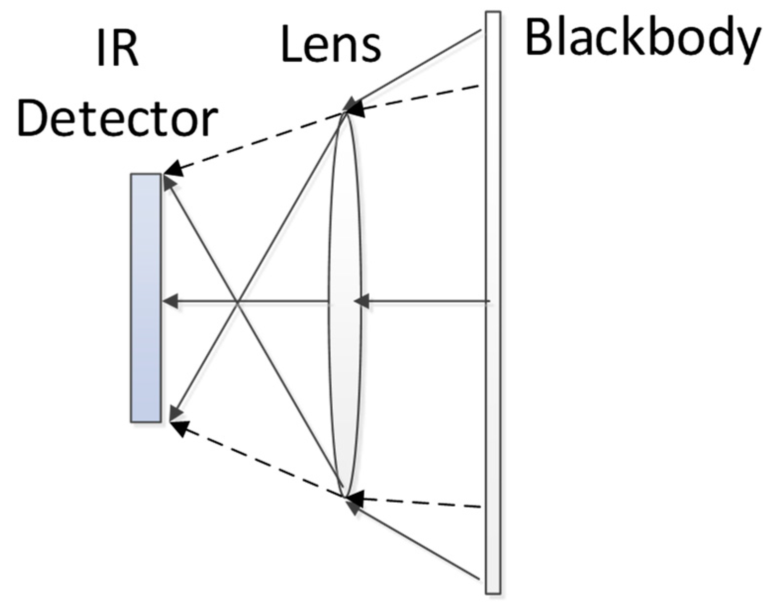
One of the most commonly used approaches of radiometric calibration for infrared thermal imager is that setting a blackbody source of large area to completely cover the field-of-view (FOV) of the infrared thermal imager [20,21,22], as shown in Figure 2.
Since the calibration is usually carried out in the laboratory and the thermal imager is very close to the blackbody, the influence of the atmosphere can be ignored, ελ = αλ = 1, τ = 1 and ε = 0. As a result, Equation (11) is simplified as:
G s = k f ( T 0 ) + G 0
where f(T0) can be calculated according to Planck’s law of radiation:
f ( T 0 ) = 1 π λ 1 λ 2 C 1 λ 5 e C 2 / λ T 0 1 d λ
In Equation (14), C1 and C2 are called the first and second radiation constants, respectively, with values C 1 = 2 π h c 2 = 3.742 × 10 16   W m 2 and C 2 = h c / k B = 1.4388 × 10 2   m K , where fundamental constants c (2.997 × 10⁸ m/s), h (6.626 × 10⁻³⁴ J s), and kB (1.381 × 10⁻²³ J/K) are the speed of light in vacuo, Planck’s constant, and Boltzmann’s constant, respectively.
In the process of radiometric calibration, it is necessary to keep laboratory conditions and thermal imager parameters unchanged. Nonuniformity correction (NUC) is often applied to make the response of each pixel identical. The procedure of radiometric calibration for an infrared thermal imager is as follows.
  • Turn off the auto gain function of the infrared thermal imager, and set focus to infinity;
  • Apply NUC to the blackbody source;
  • Save frames of image when the temperature of blackbody source is completely stable, then average the saved images to reduce random noises;
  • Collect DN value for the averaged images of different temperatures;
  • Calculate the radiance according to Equation (14);
  • Change the temperature of the blackbody and repeat the steps 3–5 until all temperatures are measured;
  • Fit DN value and the radiance in Equation (13) by the least square method.
The infrared thermal imager and the blackbody source used for radiometric calibration are shown in Figure 3.
The properties of the infrared thermal imager and the blackbody source are listed in Table 1 and Table 2, respectively.

2.4. The Proposed Blackbody-Based Method

Although MODTRAN software is widely used to estimate the transmittance, atmospheric radiation, and so on, it is only suitable for theoretical analysis not practical scenes, for MODTRAN is mainly based on the U.S atmospheric parameters which cannot represent the actual condition in the other places, especially in cities with heavy pollution. The proposed method can be considered as an alternative for practical scenes. The atmospheric transmittance and atmospheric radiation can both be derived from Equation (11) by setting two different temperatures denoted as T0H and T0L as follows:
G s H = k { τ a λ [ ε λ f ( T 0 H ) + ( 1 α λ ) f ( T u ) ] + ε a λ f ( T a ) } + G 0
G s L = k { τ a λ [ ε λ f ( T 0 L ) + ( 1 α λ ) f ( T u ) ] + ε a λ f ( T a ) } + G 0
Hence, the atmospheric transmittance and atmospheric radiation can be derived by Equation (15) minus Equation (16) and Equation (15) plus Equation (16) as follows:
τ a λ = G s H G s L k [ ε λ f ( T 0 H ) ε λ f ( T 0 L ) ]
ε a λ f ( T a ) = 1 2 { G s H + G s L 2 G 0 k τ a λ [ ε λ f ( T 0 H ) + ε λ f ( T 0 L ) + 2 ( 1 α λ ) f ( T u ) ] }
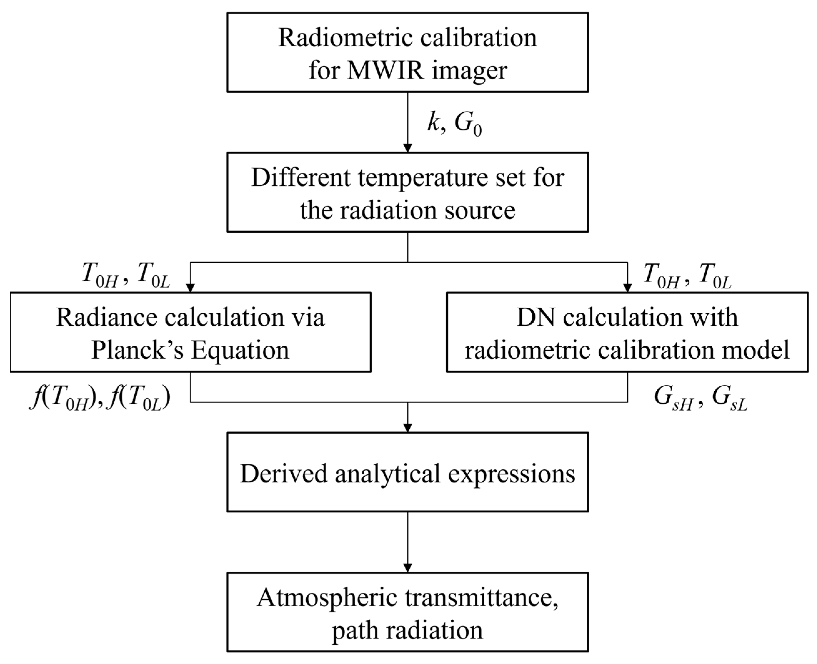
Figure 4 shows the workflow for correction of atmospheric transmission using the proposed approach.

3. Results

3.1. Radiometric Calibration for the Infrared Thermal Imager

In the process of radiometric calibration for the infrared thermal imager, two-point NUC is applied to ensure the uniformity of images from the blackbody source. In addition, we use a DALSA X64-CL iPro image acquisition card to grab 100 image frames for each temperature, and set temperatures of the blackbody increasing from 35 to 115 degrees C at interval of 5 degrees C, with DN value of pixel (320,256) collected. The radiance calculated according to Planck’ law of radiation and corresponding DN value are shown in Table 3.
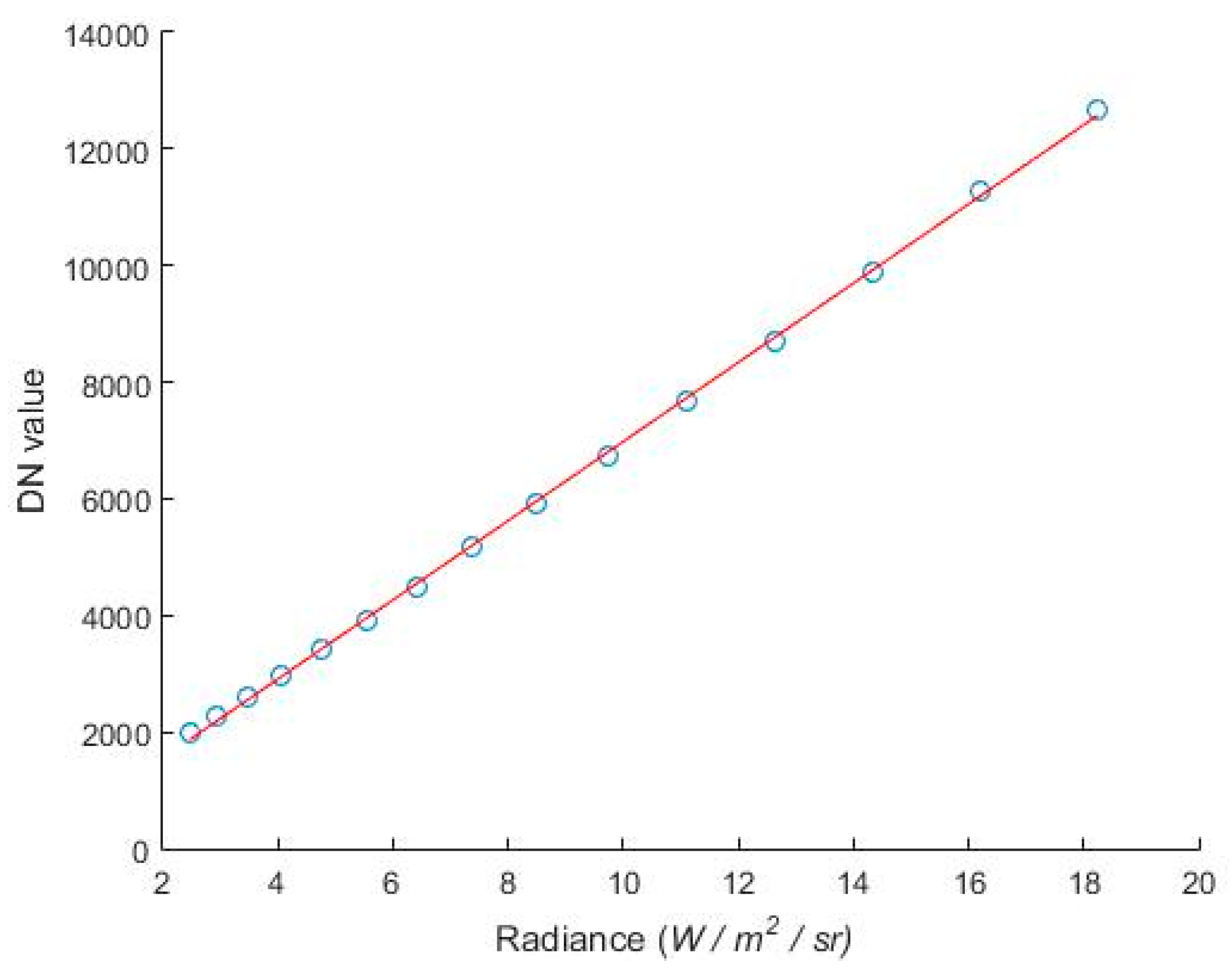
Table 3 indicates that the DN value is of little increase during the temperature increasing from 110 degrees C to 115 degrees C. Considering the 14-bit output of the thermal imager, it can be concluded that the DN value has reached a saturation point around 110 degrees C. Therefore, data from 110 to 115 degrees C is removed for the least square, and only data from 35 to 105 degrees C is used. The result of the radiometric calibration under the condition of 2 ms integration time, 300 mm focal length, is given:
G s = 679 f ( T 0 ) + 194
with the fitted straight line using least square method shown in Figure 5.

3.2. Experiments

We conduct an infrared radiation measuring experiment for the blackbody source in different temperatures. The blackbody source is settled horizontally 30 m away from the infrared thermal imager, with temperature increasing from 65 to 105 degrees C at intervals of 10 degrees C, as shown in Figure 6.
The radiance calculated according to Planck’ law of radiation and corresponding DN value are listed in Table 4.
According to Equations (17) and (18) the atmospheric transmittance τ and atmospheric radiation εf(Ta) can be calculated through least square fitting in order to reduce error, values of which are approximately 88.8% and 0.0239 W/m2/sr. In comparison with MODTRAN, the atmospheric parameters used for the blackbody test are listed in Table 5.
Input these parameters listed in Table 5 into MODTRAN, the atmospheric transmittance and atmospheric radiation are 83.9% and 0.0352 W/m2/sr, respectively. With all the parameters given above, the infrared radiation of targets can be calculated by Equation (12). The comparison of inversion results with the derivation from the analytical expression and with MODTRAN are given in Table 6. It is obvious that the inversion results derived by the expression in each row are closer to the actual radiance of the blackbody than that by MODTRAN, with the maximal error of 2.56% and 5.7% by the derivation from the analytical expression and by MODTRAN, respectively.
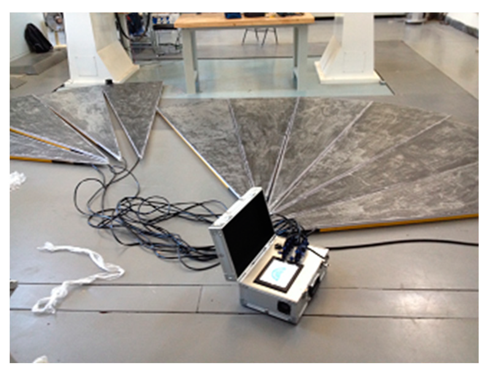
To extend the verification to other tests, we also carried out a field test for a fan-shaped infrared target. Due to the relatively small size of the blackbody, we cannot acquire enough pixels over a long distance in some cases. The target with a bigger fan-shaped infrared target is used in the experiment, which consists of 10 pieces of heating plates, each with an 18-degree central angle, the radius of 2.25 m, and the surface emissivity of 0.52. The fan-shaped target is shown in Figure 7, with the aluminum box of the temperature controller.
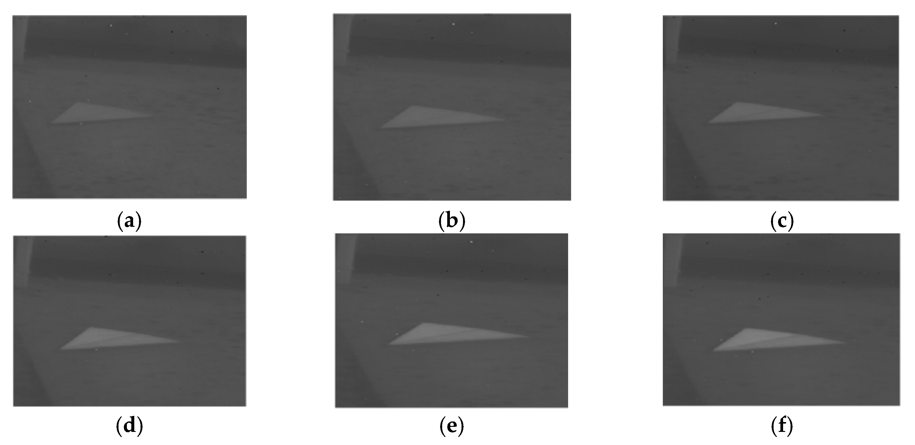
Two pieces of plates are chosen in the experiment, with the temperature increasing from 35 to 50 degrees C at intervals of 3 degrees C and with the ambient temperature of 28 degrees C, shown in Figure 8.
The atmospheric parameters for the fan-shaped target test are listed in Table 7.
The transmittance and atmospheric radiation are calculated by Equation (12) with values of 73.3% and 1.17 W/m2/sr, while by MODTRAN with values of 72.3% and 1.34 W/m2/sr, respectively. Table 8 shows the comparison of inversion results for the two hearting plates, indicating that for each row, the radiance derived from the analytical expression is also closer to the actual radiance than that from MODTRAN over a relatively long distance, with the maximal error of 10.2% and 16.7% by the derivation from the analytical expression and by MODTRAN, respectively.

4. Discussion

For long distance infrared signature of targets in the field, the inversion uncertainty is mainly affected by (1) the uncertainty of the radiometric calibration, (2) the uncertainty of the estimation for the atmospheric transmittance and atmospheric radiation, and (3) the uncertainty of the environmental condition changes in the field, such as temperature, wind, etc., other than that in the laboratory. Among these factors mentioned above, the uncertainty in the radiometric calibration, i.e., values of k and G0 in Equation (13), under current measuring conditions is approximately 6% for a medium-wave infrared thermal imager [22]. The uncertainty in the estimation of the atmospheric transmittance and atmospheric radiation, depending on meteorological equipment and MODTRAN, is about 20–30%; and the environmental differences between the field and the laboratory is usually 10%. As a result, the uncertainty of the measurement for the infrared thermal imager can be calculated by the root mean square of the three factors listed above, approximately 23.2–32.2%. In our experiments, the inversion uncertainty derived from the analytical expression and by MODTRAN is 2.56%, 10.2% and 5.7%, 16.7%, respectively, both of which are acceptable according to the above analysis. It is obvious that the uncertainty derived from the analytical expressions is lower than that by MODTRAN for cooperative targets, i.e., targets that can be easily placed a blackbody or an object that served as a blackbody nearby. However, for non-cooperative targets such as an enemy vehicle, we can only employ MODTRAN to estimate the radiation of targets theoretically.

5. Conclusions

In this paper, a blackbody-based approach for estimating the actual radiation of measured cooperative target is proposed. Firstly, radiometric calibration is carried out in the laboratory for the infrared thermal imager to determine the slope and offset used in the linear regression. Then, the radiance of the blackbody and digital number value of images are calculated with a set of different temperatures. Finally, according to the analytical expressions derived the atmospheric transmittance and atmospheric radiation are determined, and actual radiance for the cooperative target is calculated. Lab and field tests demonstrate that the uncertainty of the actual radiance of measured cooperative target calculated via the proposed method is lower than that by MODTRAN, which can be considered as an alternative for practical scenes when measuring cooperative targets in engineering application. Future studies will mainly focus on lowering the uncertainty for non-cooperative targets over long distances, which aims to reduce the impact of the atmospheric transmission to improve furtherly the infrared radiation of measured targets.

Author Contributions

Conceptualization, M.Y.; methodology, M.Y.; software, M.Y.; validation, M.Y., L.X. and X.T.; formal analysis, M.Y.; investigation, H.S.; resources, H.S.; data curation, M.Y.; writing—original draft preparation, M.Y.; writing—review and editing, L.X. and X.T.; visualization, M.Y.; supervision, X.T.; project administration, L.X.; funding acquisition, L.X. All authors have read and agreed to the published version of the manuscript.

Funding

Science and Technology Resources Shared Services Platform Construction of JiLin Province (No.20230505009ZP).

Institutional Review Board Statement

Not applicable.

Informed Consent Statement

Not applicable.

Data Availability Statement

The data presented in this study are available from Table 3, Table 4, Table 5, Table 6, Table 7 and Table 8.

Conflicts of Interest

The authors declare no conflict of interest.

References

  1. Jacobs, A. Thermal Infrared Characterization of Ground Targets and Backgrounds; SPIE Optical Engineering Press: Washington, DC, USA, 1996; pp. 140–149. [Google Scholar]
  2. Mahulikar, P.; Sonawane, R.; Arvind Rao, G. Infrared signature studies of aerospace vehicles. Prog. Aerosp. Sci. 2007, 43, 218–245. [Google Scholar] [CrossRef]
  3. Zhao, B.; Xiao, S.; Lu, H.; Wu, D. Modeling and simulation of infrared signature of remote aerial targets. In Proceedings of the 2017 10th International Congress on Image and Signal Processing, BioMedical Engineering and Informatics (CISP-BMEI), Shanghai, China, 14–16 October 2017; pp. 1–5. [Google Scholar] [CrossRef]
  4. Zhang, Y.-C.; Chen, Y.-M.; Fu, X.-B.; Luo, C. The research on the effect of atmospheric transmittance for the measuring accuracy of infrared thermal imager. Infrared Phys. Technol. 2016, 77, 375–381. [Google Scholar] [CrossRef]
  5. Leslie, P.; Furxhi, O.; Short, R.; Grimming, R.; Driggers, R. Mid-Wave and Long-Wave Infrared Signature Model and Measurements of Power Lines Against Atmospheric Path Radiance. In Proceedings of the 2021 IEEE Research and Applications of Photonics in Defense Conference (RAPID), Miramar Beach, FL, USA, 2–4 August 2021; pp. 1–2. [Google Scholar] [CrossRef]
  6. Talghader, J.J.; Gawarikar, A.S.; Shea, R.P. Spectral selectivity in infrared thermal detection. Light. Sci. Appl. 2012, 1, 6–16. [Google Scholar] [CrossRef] [Green Version]
  7. Qiu, H.; Hu, L.; Zhang, Y.; Lu, D.; Qi, J. Absolute Radiometric Calibration of Earth Radiation Measurement on FY-3B and Its Comparison With CERES/Aqua Data. IEEE Trans. Geosci. Remote Sens. 2012, 50, 4965–4974. [Google Scholar] [CrossRef]
  8. Poline, M.; Rebrov, O.; Larsson, M.; Zhaunerchyk, V. Theoretical studies of infrared signatures of proton-bound amino acid dimers with homochiral and heterochiral moieties. Chirality 2020, 32, 359–369. [Google Scholar] [CrossRef] [PubMed]
  9. Liu, J.; Yue, H.; Lin, J.; Zhang, Y. A Simulation Method of Aircraft Infrared Signature Measurement with Subscale Models. Procedia Comput. Sci. 2019, 147, 2–16. [Google Scholar] [CrossRef]
  10. Knežević, D.M.; Matavulj, P.S.; Nikolić, Z.M. Modeling of aircraft infrared signature based on comparative tracking. Optik 2021, 225, 165782. [Google Scholar] [CrossRef]
  11. Zhang, D.; Bai, L.; Wang, Y.; Lv, Q.; Zhang, T. An improved SHDOM coupled with CFD for simulating infrared radiation signatures of rocket plumes. Infrared Phys. Technol. 2022, 122, 104054. [Google Scholar] [CrossRef]
  12. Xu, M.; Bu, X.; Yu, J.; He, Z. Spinning projectile’s attitude measurement with LW infrared radiation under sea-sky background. Infrared Phys. Technol. 2018, 90, 214–220. [Google Scholar] [CrossRef]
  13. Haq, F.; Huang, J. Parametric design and IR signature study of exhaust plume from elliptical-shaped exhaust nozzles of a low flying UAV using CFD approach. Results Eng. 2022, 13, 100320. [Google Scholar] [CrossRef]
  14. Cheng, W.; Wang, Z.; Zhou, L.; Shi, J.; Sun, X. Infrared signature of serpentine nozzle with engine swirl. Aerosp. Sci. Technol. 2019, 86, 794–804. [Google Scholar] [CrossRef]
  15. Ata, Y.; Nakiboğlu, K.C. IR signature estimation of an object or a target by taking into account atmospheric effects. Opt. Commun. 2010, 283, 3901–3910. [Google Scholar] [CrossRef]
  16. Berk, A.; Anderson, G.P.; Bernstein, L.S.; Acharya, P.K.; Dothe, H.; Matthew, M.W.; Adler-Golden, S.M.; Chetwynd, J.H., Jr.; Richtsmeier, S.C.; Pukall, B.; et al. MODTRAN4 radiative transfer modeling for atmospheric correction. In Proceedings of the SPIE’s International Symposium on Optical Science, Engineering, and Instrumentation, Denver, CO, USA, 18–23 July 1999; pp. 348–353. [Google Scholar] [CrossRef]
  17. Ni, N.; Zhang, K.; Hu, J.; Li, L.; Mi, S.; Zhang, Y.; Zhang, Y. Combined Use of Blackbody and Infrared Radiation for Accurate Measurement of Temperature Field of Aluminum Alloys. Optik 2022, 268, 169763. [Google Scholar] [CrossRef]
  18. Shen, J.; Zhang, Y.; Xing, T. The study on the measurement accuracy of non-steady state temperature field under different emissivity using infrared thermal image. Infrared Phys. Technol. 2018, 94, 207–213. [Google Scholar] [CrossRef]
  19. Zhang, Y.-C.; Chen, Y.-M.; Luo, C. A method for improving temperature measurement precision on the uncooled infrared thermal imager. Measurement 2015, 74, 64–69. [Google Scholar] [CrossRef]
  20. Yang, G.; Yu, Y.; Sun, Z.; Li, Z.; Pang, X.; Zhang, T. Radiometric calibration algorithm for high dynamic range infrared imaging system. Infrared Phys. Technol. 2023, 130, 104607. [Google Scholar] [CrossRef]
  21. Lin, D.; Cui, X.; Wang, Y.; Yang, B.; Tian, P. Pixel-wise radiometric calibration approach for infrared focal plane arrays using mul-tivariate polynomial correction. Infrared Phys. Technol. 2022, 123, 104110. [Google Scholar] [CrossRef]
  22. Li, Z.; Yu, Y.; Tian, Q.-J.; Chang, S.-T.; He, F.-Y.; Yin, Y.-H.; Qiao, Y.-F. High-efficiency non-uniformity correction for wide dynamic linear infrared radiometry system. Infrared Phys. Technol. 2017, 85, 395–402. [Google Scholar] [CrossRef]
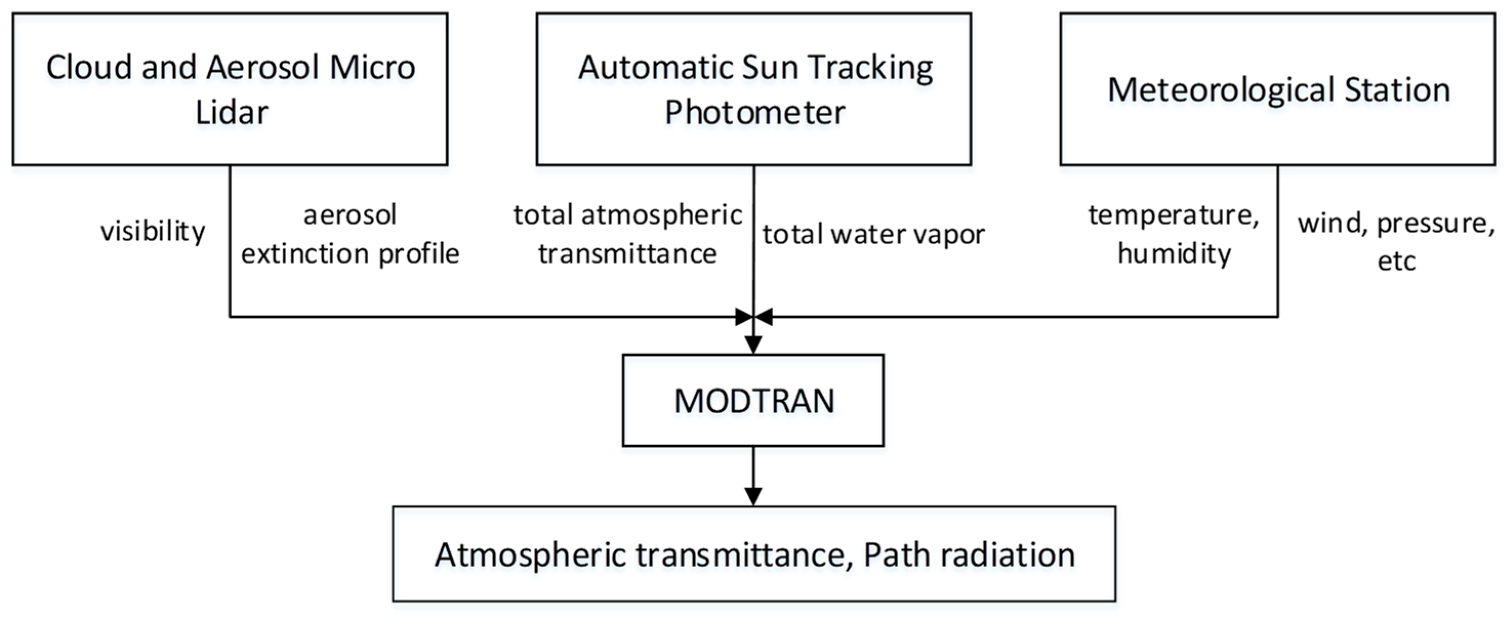
Figure 1. Workflow for MODTRAN software using measured atmospheric parameters.
Applsci 13 04832 g001
Figure 2. Schematic diagram of the radiometric calibration.
Applsci 13 04832 g002
Figure 3. The infrared thermal imager and the blackbody source. (a) Infrared thermal imager; (b) Blackbody source.
Applsci 13 04832 g003
Figure 4. Workflow for the proposed method.
Applsci 13 04832 g004
Figure 5. Fitted straight line with the least square method.
Applsci 13 04832 g005
Figure 6. Blackbody source in field test with different temperatures in degree C: (a) 65; (b) 75; (c) 85; (d) 95; (e) 105.
Applsci 13 04832 g006
Figure 7. Heating plates used in the field test.
Applsci 13 04832 g007
Figure 8. Heating plates with different temperatures in degree C: (a) 35; (b) 38; (c) 41; (d) 44; (e) 47; (f) 50.
Applsci 13 04832 g008
Table 1. Properties of the infrared thermal imager.
ParameterValue
ManufacturerFLIR Systems
ModelMINICORE-600Z
Band Range3.7–4.8 μm
Resolution640 × 512 pixel
Pixel Size15 μm × 15 μm
Output Bit14 bit
F#F4
Focus30–600 mm continuous zooming
Cooling TypeStirling cooling
Table 2. Properties of the blackbody source.
ParameterValue
ManufacturerCI Systems
ModelSR800-12LT
Size305 mm × 305 mm
Temperature range−40–150 °C
Emissivity0.97 ± 0.02
Uniformity±0.03 °C
Table 3. Radiance and DN value collected in the radiometric calibration.
Temperature/°CRadiance/W·m−2·str−1DN Value
352.47641986
402.93562257
453.46272584
504.06492979
554.75013399
605.52673900
656.40344491
707.38965162
758.49505904
809.72996722
8511.10517668
9012.63188717
9514.32169880
10016.186611,295
10518.239512,658
11020.493315,106
11522.961415,114
Table 4. Radiance and DN value for the blackbody test.
Temperature/°CRadiance/W·m−2·str−1DN Value
656.40344072
758.49505298
8511.10516764
9514.32168605
10518.239511,207
Table 5. Atmospheric parameters used in MODTRAN for the blackbody test.
Atmospheric ParametersValue
Atmospheric profileMid-latitude summer
Altitude of observer (km)0.216
Visibility (km)13
Humidity (%)54
Temperature (°C)20
Atmospheric pathhorizontal
Distance from observer to target (m)30
CO2 mixing ratio (ppmv)370
Table 6. Comparison of inversion results for the blackbody source.
Temp
(°C)
DN
Value
Actual Radiance (W/m2/sr)Radiance with MODTRAN (W/m2/sr)Error with MODTRAN
(%)
Radiance with Derivation
(W/m2/sr)
Error with Derivation
(%)
6540726.40346.76545.66.43480.48
7552988.49508.91744.98.46960.29
85676411.105111.49083.410.90101.83
95860514.321614.72242.713.95522.55
10511,20718.239519.28995.718.27310.18
Table 7. Atmospheric parameters used in MODTRAN for the fan-shaped target test.
Atmospheric ParametersValue
Atmospheric profileMid-latitude summer
Altitude of observer (km)0.22
Visibility (km)13
Humidity (%)45
Temperature (°C)28
atmospheric pathslant
distance from observer to target (m)1560
CO2 mixing ratio (ppmv)370
Table 8. Comparison of inversion results for heating plates.
Temp
(°C)
DN
Value
Actual Radiance (W/m2/sr)Radiance with MODTRAN (W/m2/sr)Error with MODTRAN
(%)
Radiance with Derivation
(W/m2/sr)
Error with Derivation
(%)
3516302.47642.0611−16.72.47890.10
3817012.74422.3392−14.82.75320.33
4118233.03542.8171−7.23.22466.2
4419443.35153.2911−1.83.692210.2
4719783.69413.4243−7.33.82353.5
5020414.06493.6711−9.74.06690.05
Disclaimer/Publisher’s Note: The statements, opinions and data contained in all publications are solely those of the individual author(s) and contributor(s) and not of MDPI and/or the editor(s). MDPI and/or the editor(s) disclaim responsibility for any injury to people or property resulting from any ideas, methods, instructions or products referred to in the content.