Article

Discontinuous Yielding of Fe E420 under High Strain Rate Loading

1
Department of Chemical, Materials and Production Engineering, University of Naples Federico II, Piazzale V. Tecchio 80, 80125 Naples, Italy
2
Department of Civil and Mechanical Engineering, University of Cassino and Southern Lazio, 03043 Cassino, Italy
*
Author to whom correspondence should be addressed.
Appl. Sci. 2023, 13(8), 5164; https://doi.org/10.3390/app13085164
Submission received: 10 March 2023 / Revised: 5 April 2023 / Accepted: 18 April 2023 / Published: 21 April 2023

Abstract

:
The discontinuous yielding behaviour of Fe E420 steel was experimentally investigated through tensile tests conducted on laminated sheets. In order to assess the response under both quasi-static and dynamic loading conditions, uniaxial tensile tests were performed according to ASTM E8 standards, and dynamic tests were conducted on the Hopkinson bar using a specially designed flat specimen. Three nominal strain rates ( 2 × 10 4 , 500, and 1000) s 1 were considered. The effect of heat treatment on the material was also considered. For this purpose, the proposed experimental campaign was carried out on both the as-is material and on one treated by water quenching. All dynamic tests were performed with the direct tensile split Hopkinson pressure bar and were recorded via a high frame rate camera. The post failure fracture surfaces were investigated using scanning electron microscopy technique.

1. Introduction

The discontinuous yielding (DY) is a phenomenon affecting the mechanical response of low-carbon steels and many types of alloys and polymers subjected to tensile deformation, by straddling the elastic and plastic transition phases [1]. It is characterized by a first material yielding point, referred to as the upper yield, followed by a rapid drop of the stress, named the lower yield. For metals exhibiting this behaviour, the lower yield point is assumed to be the reference for the yielding strength definition. Then, a quasi-constant plastic stress value can arise. The deformation range under-laying this plateau is referred to as the yield-point elongation (YPE) [2]. The lower yielding is related to the plastic strain localization on propagating slipping regions, named Luders bands. Once the Luders bands completely affect the material, the plastic flow redistribution produces a renewed stress growth [3]. The DY origins were extensively investigated in the literature and were found to be related to the dislocation mobility inhibition phenomenon [4,5,6]. In body-centred cubic (BCC) and face-centred cubic (FCC) metals, the presence of small interstitial atoms, such as carbon or nitrogen, can restrict the dislocation mobility [7]. The phenomenon is driven by a preferred diffusion of the interstitial atoms towards the dislocation core. It is promoted by the relaxation of the residual stress field caused by the distortion of crystal lattice surrounding the atoms [8]. The presence of interstitial atoms into the dislocation core results in a reduced mobility of the same. This dislocation pinning is known in the literature as the Cottrell atmosphere [9]. As a consequence of this condition, an extra amount of load is needed to unpin the dislocations prior to the yielding occurring, and producing an upper yield point. The dislocations are then free to move in the crystal lattice, resulting in the Luders plateau characterizing the lower yield point. The dislocation unpinning is a reversible phenomenon, since a sufficiently long rest of the material after the unloading enables the interstitial atoms to re-diffuse back to the dislocation core. This results in a return of the DY that does not occur if the material is immediately reloaded. The described effect is referred to as strain-ageing [10]. For these reasons, the DY needs to be carefully considered in those engineering applications where mild steels are used. Cottrell and Bilby [9] first formalized a relation describing the threshold stress for the dislocation unpinning. Yokobori et al. [11] proposed a methodology to compute the yield stress values by defining a function for the Cottrell–Bilby activation energy. The DY behaviour is also strongly influenced by the material operating temperature, thermal treatments and crystalline structure. Gao et al. [12] demonstrated a high-purity iron that can exhibit both DY and continuous yielding in the dependence of the post-annealing cooling velocity. They showed that this behaviour is related to the average material grain size, resulting from the treatment. Hutchinson et al. [13] obtained high upper yielding values in uniaxial tensile tests on non-uniformly annealed mild steel wire. The same testing method was adopted by Sun et al. [14], both for uniformly and non-uniformly annealed mild steel. They observed that the non-uniformly annealed specimens’ upper yield stress was almost twofold of the lower yield stress, while an negligible difference resulted from the uniformly annealed specimens. The occurrence of the initial yielding at the specimens gauge length in the non-uniformly annealed specimens confirmed that the upper yielding value was caused by the material’s properties and not a clamping-induced stress concentration. Conversely, the uniformly annealed specimens’ initial yielding was localized close to the fixture system, suggesting that the DY negligibility is produced by a fixture-induced stress concentration effect, and it is not an actual material behaviour. Zhang L.C. et al. [15] demonstrated that both pre-straining and bake hardening treatments can induce a DY behaviour in two CMnSi transformation-induced plasticity (TRIP) steels. They concluded that it is due to the treatments-induced micro structural changes, such as an increase in the dislocation density and the formation of fine precipitation in bainite and martensite. The strain-rate dependency of a dislocation pinning dependent DY was observed by E.M.C BESAG and R. E. Smallman [16] in centre-annealed wires of three alloys Ni3Mn, Ni3Fe and Ni3Fe-5%. The DY phenomenon in Ti-40 at.% Al alloy, was investigated by Dai-Xiu Wei et al. [17], at strain rates in the range of 1 ÷ 0.001 s 1 . The ratio between the upper and lower yields was found to increase with the strain-rate. Further, a strong correlation between the micro-structural evolution and the DY in the dependence of the strain-rate was found. In contrast, a negligible upper yielding was observed for the thermally treated Al-2024 alloys. It was associated with a flow stress decreasing with the strain-rate in fully annealed material, while an opposite trend was found in fully aged material [18]. R.A. Varin et al. [19] studied the DY in ultra-fine-grained austenitic stainless steels under temperature. They found no systematic dependence on the Luders strain on the strain-rate and a drastic increase of the plateau stress with the temperature decrease in 316 steel. Since its dependence on material micro-structure, dislocation and interstitial atom density, as well as thermal treatment, temperature and strain-rate, the DY characterization is complex and still not a completely unravelled phenomenon. For this reason, the main aim of the present work is to investigate the DY of the quenched Fe E420. It is a low carbon steel widely adopted in automotive and transportation fields, both for structural and non-structural components. Since these components may be subjected to static and dynamic loads over their life cycle, a comprehensive characterization of the material response under the described conditions produces results of great interests. For these reason, in the present work, the DY behaviour of both thermally treated and as-is Fe E420 steel was investigated under three different strain rates equal to ( 2 × 10 4 , 500 , and 1000 ) s 1 .

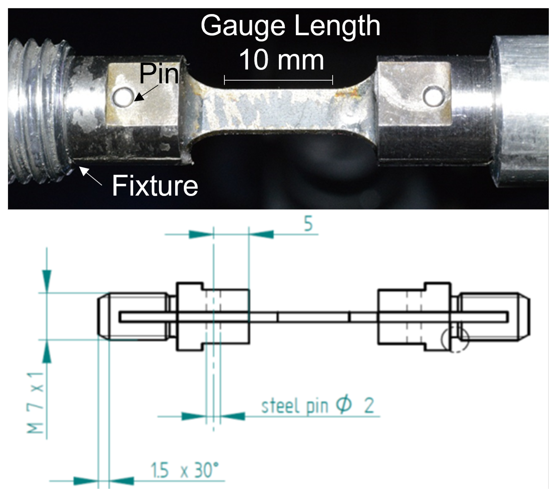
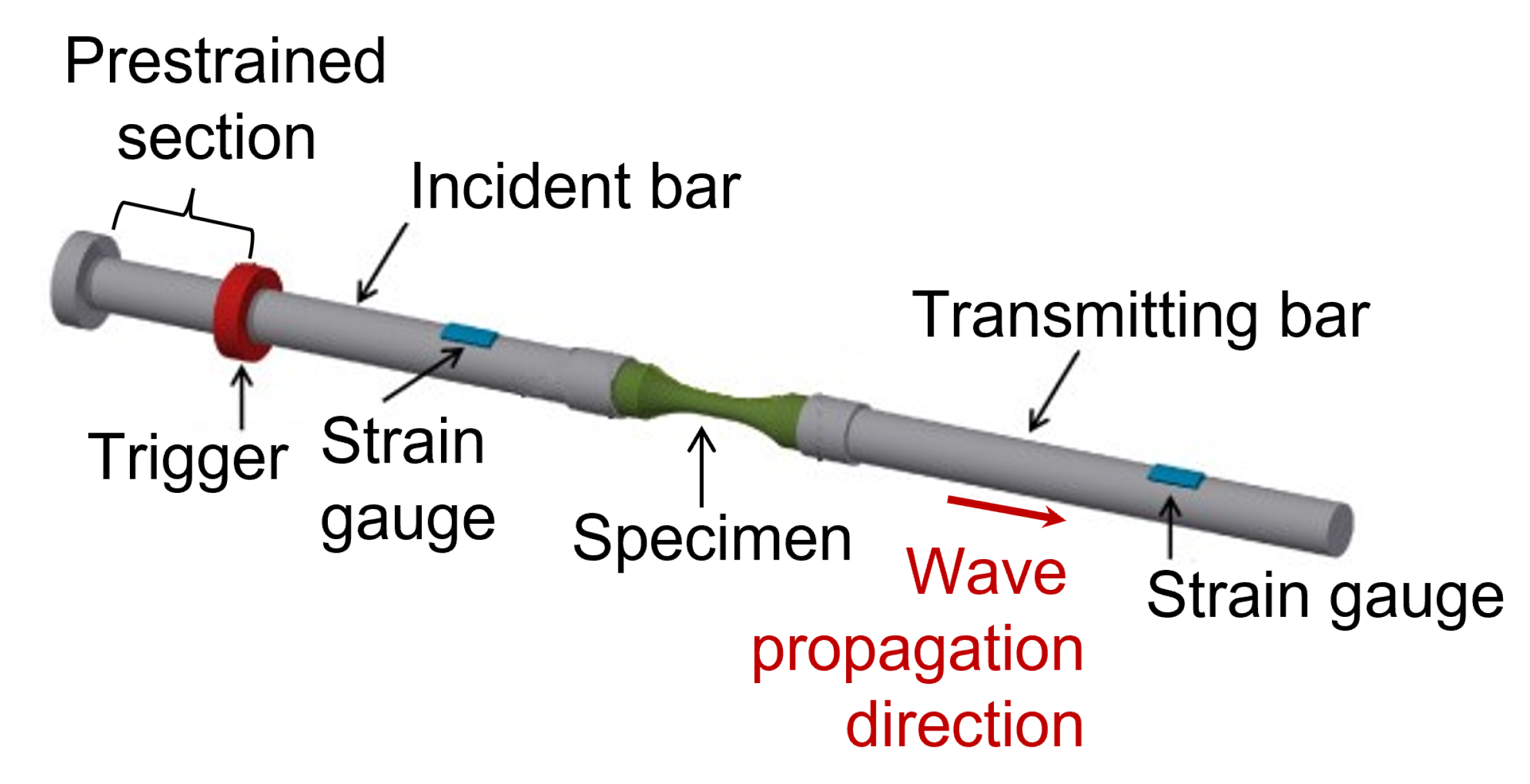
2. Materials and Methods
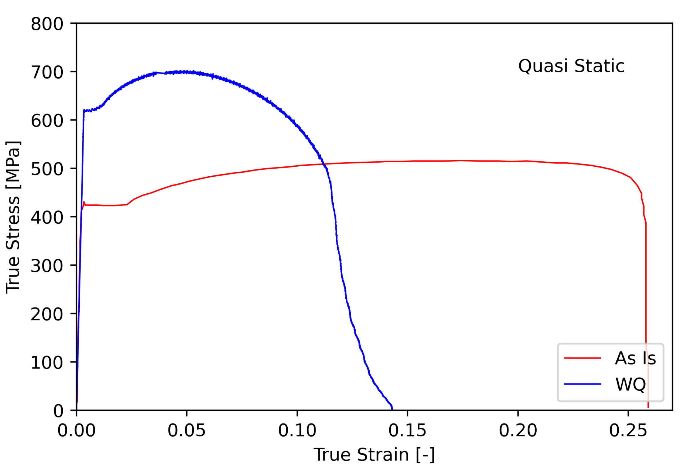
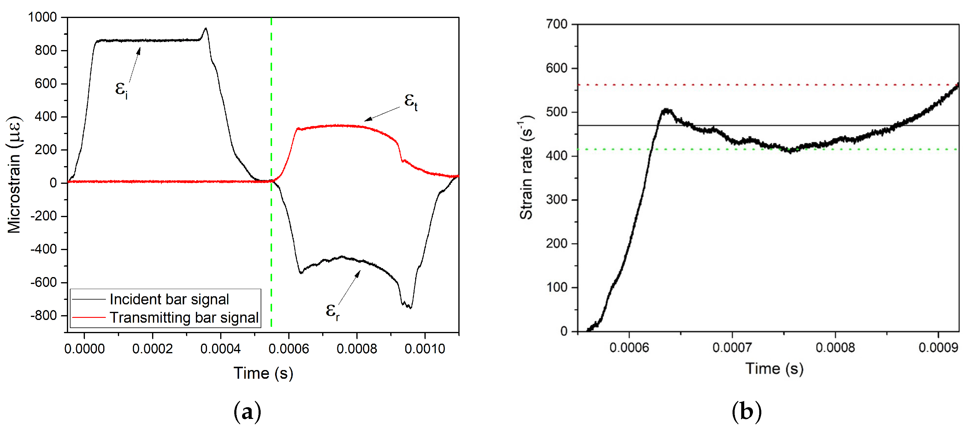
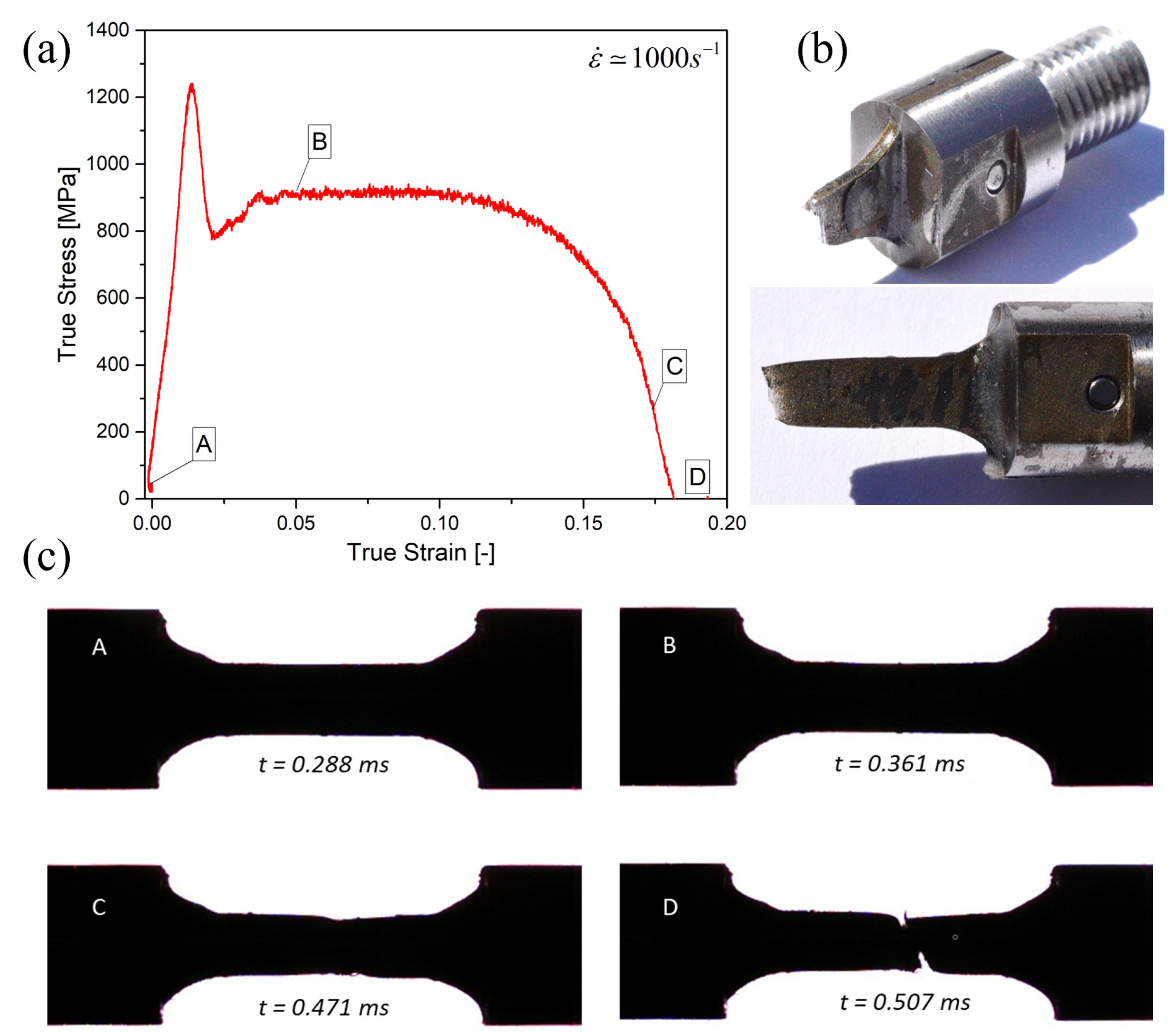
The investigated Fe E420 was in form of 1 mm thick laminated sheet for industrial applications. The experimental campaign was conducted on both the as-is and thermally treated material. The thermal treatment was a water quenching (WQ) process. It consists in heating the material to a temperature over the 800 °C and a subsequent cooling performed in a water bath. The treatment effectiveness was assessed through the execution of Vickers hardness tests both before and after the treatment. In Table 1, the measured treatment temperature is reported together with the Vickers hardness values. The quenching treatment effectiveness was confirmed by the resulting 40 % Vickers hardness increment.
The experimental campaign consisted in quasi-static and dynamic tensile tests, with the specimens machined from the metal sheets. Quasi-static tensile tests, performed according to the ASTM E8 standard, were conducted under displacement controls using an electro-mechanical testing machine Instron 5566 equipped with a 100 kN load cell. The specimens were flat dog bone-shaped, with a gauge length equal to 80 mm. To measure the strain during the tensile tests, a 25 mm gauge length extensometer was adopted. The quasi-static testing conditions were ensured by applying a strain-rate equal to 2 × 10 4 s 1 .
The dynamic tests were conducted via a direct tensile split Hopkinson pressure bar (DT-SHPB) [20] at a nominal strain-rate of ( 500 and 1000 ) s 1 . A specific geometry for the specimens was designed, since the standard Hopkinson bar specimens had a round section, while the studied material was in the form of a sheet. A specific threaded fixture was designed to lodge a dog bone-shaped specimen with a gauge length equal to 10 mm. To guarantee the elastic wave transmission, the specimen was pinned and glued to the fixture. The specimen and the fixture system are here reported in Figure 1.
As schematically reported in Figure 2, the DT-SHPB system consists of two metallic bars connected by the specimen with its fixture system. At the initial section of one bar, referred to as the incident bar, a stress wave is generated by instantly releasing a pre-strained portion of the bar itself. The resulting stress wave has an amplitude equal to half of the pre-tension stress, and moves toward the specimen. Due to difference in mechanical impedance of the specimen with respect to the bars, part of the wave is reflected back into the incident bar and the reminder is transmitted through the specimen to the other bar, referred to as the transmitting bar. The propagating waves within the bars were measured through a strain gauge located in the middle of each bar. The resulting strength curve of the specimen, i.e., the stress-strain curve, can be obtained from the analysis and manipulation of the incident and transmitted waves. The strain-rate ε ˙ ( t ) can be calculated according to Equation (1), where C 0 is the wave propagation speed within the bars, L s is the specimen gauge length and ε r ( t ) is the reflected wave strain.
ε ˙ ( t ) = 2 · C 0 L s · ε r ( t )
Since the parameters in (1), as well as the reflected wave signal, are known, the expression can be calculated and also integrated to obtain the specimen engineering strain ε ( t ) . Then, the engineering stress σ ( t ) can be calculated according to Equation (2), where E b is the bar material Young modulus, A s and A b are, respectively, the specimen and bars cross section net area, and ε t ( t ) is the transmitted wave strain.
σ ( t ) = E b · A b A s · ε t ( t )
It should be noted that (1) and (2) are explicitly time dependent. To avoid the time variable from the expression, the reflected and transmitted waves need to be in one phase. The whole quality of the tests depends on the continuity in the wave propagation, on the wave phase and on the incident wave shape. With the purpose to investigate the specimen deformation field over the dynamic tests, a high-frame rate camera Phantom v7.3 series was adopted. The specimen silhouette was acquired through the tests with a frequency equal to 28,000 frames per second and a resolution of 324 × 152 pixels. The camera frames were synchronized in post-processing with respect to the acquired stress and strain data. With the purpose to assess the damage mechanisms under dynamic testing conditions, the specimen fracture surfaces where acquired using the scanning electron microscopy (SEM) technique using a Hitachi TM3000 device. The experimental test results, analysed with the purpose to estimate the DY material response in the dependence of the quenching treatment and strain-rate, are going to be presented and discussed in the following sections.

3. Results

In Figure 3, the quasi-static test results are reported in the form of tensile stress to strain. Independent of the treatment, the result of a material Young modulus (E) was equal to 193 ± 3 GPa. It can be seen that Fe E420 under the described conditions does not show a noticeable DY behaviour. Once the yielding point ( σ y ) reached a stress value of 425 MPa, interestingly, we obtained a Luders plateau with a YPE of about the 2.6 % of strain. Then, the stress increased slightly toward a plastic plateau until the failure occurred at a strain to failure ( ε f ) equal to 28 % .
Interestingly, the maximum reached stress ( σ m a x ) resulted in a wide range of strain that was equal to 519 MPa. The stress to stain curves, resulting from the quenched material, produced a substantially different behaviour. The treatment produced a much higher yielding point ( 630 MPa) associated to a more pronounced hardening behaviour. A reduced Luders plastic plateau was visible and the maximum stress, equal to 702 MPa, was obtained for a strain-rate in the range of 3.5 ± 4.5 % . Furthermore, the strain to failure was strongly reduced by the quenching, resulting in measurements halved compared to the as-is material. The discussed stress and strain characteristic values are here collected in Table 2 for both tested conditions.
The dynamic test output data processing started from the Hopkinson bar wave analysis. In Figure 4a, the incident ( ε i ) the reflected ( ε r ) and the transmitted ( ε t ) waves were reported over the time for the test performed at 500 s 1 . The test execution time can be divided in two periods, the incident wave propagation time and the transmitted and reflected wave propagation time. The incident wave is measured on the incident bar as well as the reflected wave, while the transmitted wave, representing the specimen loading signals, was acquired on the transmitting bar. The green dashed line in Figure 4a sets the time at which the wave signals, coming from the specimen, were detected. The flat shape of the incident wave proves the successful execution of the test.
The actual applied strain-rate can be calculated, starting from the reflected wave signal, according Equation (1). The strain-rate over the test time for the considered test, is reported in Figure 4b. As expected, it is not constant over the test: it reaches a first peak value of 500 s 1 ; then, because of the specimen elongation, it decreases to a minimum value of 412 s 1 (green dotted line); and, after that, due to the specimen necking, it rises again to 554 s 1 (red dotted line) just before the specimen failure. The mean value of strain-rate over the test was so calculated from the curve, between the exposed maximum and minimum values, and is equal to 470 s 1 . Similar considerations were made for all of the conducted tests. The tests at a higher strain-rate also resulted in an average value close to the desired nominal of 1000 s 1 . The stress over strain curve for the 1000 s 1 test, is here reported in Figure 5a, as an example. A DY behaviour can be clearly appreciated. In Figure 5b, two images of the failed specimen are reported. The deformation field as well as the necking phenomenon evolution during the tests were monitored through the high frame rate camera acquisition. In Figure 5c, a collection of four frames from the tests are presented. The corresponding stress to strain conditions and frame time are also specified. A noticeable necking occurs before the specimen failure.
The dynamic test failure mechanism was further investigated through fracture surface SEM analysis. For the sake of brevity, only the 1000 s 1 test will be presented and discussed; nevertheless, the same results emerged also from the 500 s 1 fractography. The fracture surface images are reported in Figure 6, both for the close to the section edge region (a) and for the central region of the section (b). Despite the high strain-rate applied, the failure mechanism results are still ductile, since the void nucleation and growth can be clearly appreciated. Further, the presence of elongated voids suggests that a void shading phenomenon occurred in the region close to the edge section, while in the central section, the round and regular voids indicate that this phenomenon did not occur.
The dynamic tests results have been collected in two groups according to the strain-rate. The 500 s 1 and 1000 s 1 true stress over true strain curves are presented in Figure 7a,b. Both for the WQ and the as-is material, a minimum of three tests were performed for each loading condition. The resulting loading curves are then represented in the form of the mean and deviation of the stress over the strain. Independent of the applied strain-rate, an increase in the yielding stress, as well as the maximum stress, was observed for all of the tested specimens. Further, the dynamic testing regime produced a missing Luders plateau and a presence of the DY phenomenon in the as-is specimens. At the lower strain-rate, only the as-is material presented a discernible upper yielding point. While, at the higher strain-rate, both the considered WQ and as-is specimens showed marked upper and lower yielding points.

4. Discussion

The conducted experimental investigation dealt with the DY in Fe E420. The onset of the discontinuous yielding was observed for both the quenched and as-is state of the material tested at higher strain-rates. The quenching treatment produced a reduction in strain to failure and a rise in the maximum stress and hardening. As the strain-rate increased, the onset of a lower and an upper yield point, not present under quasi-static test conditions, became gradually clear. Figure 8 shows the evolution of the lower and upper yield points at the three considered deformation rates, both for the quenched and as-is material.
The gap between the lower and upper yield points greatly increases for the higher considered strain-rate of 1000 s 1 . Moreover, this gap is about 250% higher for the quenched material when compared to the as-is state, highlighting an important effect of the heat treatment on the discontinuous yielding phenomenon. The described experimental results lead to the following conclusion:
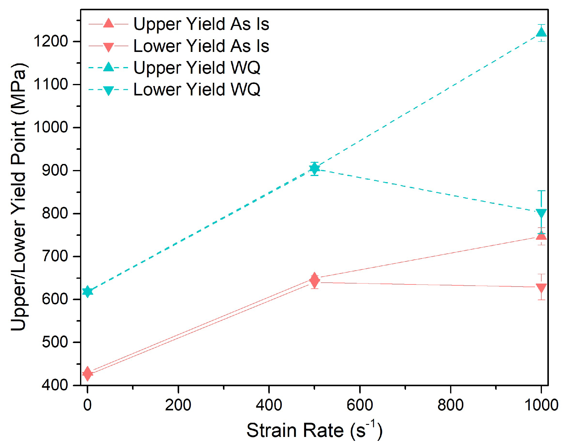
  • A reserve of elastic strength for the as-is Fe E420 and even more for the quenched Fe E420 when loaded at a strain-rate higher than 500 s 1 can be considered.
This represents a beneficial effect in all of those stress-controlled applications where plastic strain has to be inhibited. In addition, since the elastic regime is much more extended, the accumulation of plastic strain can be avoided by preventing low cycle failures under fatigue loading at high strain rates.
Consequently, the DY phenomenon should not be neglected since it could significantly extend the range of applications of materials in sectors, such as aerospace and defence.

Author Contributions

Conceptualization, L.E. and M.B.; Formal analysis, L.E.; Experimental investigation, G.I. and F.S.; Writing–original draft preparation, M.B.; Writing–review and editing, L.E.; Supervision and project administration, L.E.; All authors have read and agreed to the published version of the manuscript.

Funding

This research received no external funding.

Informed Consent Statement

Not applicable.

Data Availability Statement

Data available on request from the authors.

Conflicts of Interest

The authors declare no conflict of interest.

Abbreviations

The following abbreviations are used in this manuscript:
DYDiscontinuous Yielding
YPEYield Point Elongation
DT-SHPBDirect Tensile Split Hopkinson Pressure Bar
WQWater Quenching
BCCBody-Centered Cubic
FCCFace-Centered Cubic
TRIPTransformation-Induced Plasticity

References

  1. Messerschmidt, U. Dislocation Dynamics during Plastic Deformation; Springer Science & Business Media: Berlin/Heidelberg, Germany, 2010; Volume 129. [Google Scholar]
  2. Smallman, R.; Ngan, A. (Eds.) Chapter 9—Plastic Deformation and Dislocation Behaviour. In Modern Physical Metallurgy, 8th ed.; Butterworth-Heinemann: Oxford, UK, 2014; pp. 357–414. [Google Scholar] [CrossRef]
  3. Butler, J. Lüders front propagation in low carbon steels. J. Mech. Phys. Solids 1962, 10, 313–318. [Google Scholar] [CrossRef]
  4. Abel, A.; Muir, H. The Bauschinger effect and discontinuous yielding. Philos. Mag. 1972, 26, 489–504. [Google Scholar] [CrossRef]
  5. Wang, Y.; Tomota, Y.; Ohmura, T.; Gong, W.; Harjo, S.; Tanaka, M. Continuous and discontinuous yielding behaviors in ferrite-cementite steels. Acta Mater. 2020, 196, 565–575. [Google Scholar] [CrossRef]
  6. Wilson, D. Role of grain boundaries in the discontinuous yielding of low-carbon steels. Met. Sci. J. 1967, 1, 40–47. [Google Scholar] [CrossRef]
  7. Hale, C.; Rollings, W.; Weaver, M. Activation energy calculations for discontinuous yielding in Inconel 718SPF. Mater. Sci. Eng. A 2001, 300, 153–164. [Google Scholar] [CrossRef]
  8. Cottrell, A.H. Dislocations and plastic flow in crystals. Am. J. Phys. 1954, 22, 242–243. [Google Scholar] [CrossRef]
  9. Cottrell, A.H.; Bilby, B.A. Dislocation theory of yielding and strain ageing of iron. Proc. Phys. Soc. Sect. A 1949, 62, 49. [Google Scholar] [CrossRef]
  10. Van Den Beukel, A.; Kocks, U. The strain dependence of static and dynamic strain-aging. Acta Metall. 1982, 30, 1027–1034. [Google Scholar] [CrossRef]
  11. Yokobori, T. The Cottrell-Bilby theory of yielding of iron. Phys. Rev. 1952, 88, 1423. [Google Scholar] [CrossRef]
  12. Gao, S.; Shibata, A.; Chen, M.; Park, N.; Tsuji, N. Correlation between continuous/discontinuous yielding and Hall–Petch slope in high purity iron. Mater. Trans. 2014, 55, 69–72. [Google Scholar] [CrossRef]
  13. Hutchinson, M. High upper yield point in mild steel. J. Iron Steel Inst. 1957, 186, 431–432. [Google Scholar]
  14. Sun, H.B.; Kaneda, Y.; Ohmori, M.; Yoshida, F. Effect of stress concentration on upper yield point in mild steel. Mater. Trans. 2006, 47, 96–100. [Google Scholar] [CrossRef]
  15. Zhang, L.; Timokhina, I.; La Fontaine, A.; Ringer, S.; Hodgson, P.; Pereloma, E. Effect of pre-straining and bake hardening on the microstructure and mechanical properties of CMnSi TRIP steels. La Metall. Ital. 2009, 101, 49–55. [Google Scholar]
  16. Besag, F.; Smallman, R. Discontinuous yielding in ordering alloys. Acta Metall. 1970, 18, 429–435. [Google Scholar] [CrossRef]
  17. Wei, D.X.; Koizumi, Y.; Chiba, A. Discontinuous yielding and microstructural evolution of Ti-40 at.% Al alloy compressed in single α-hcp phase region. J. Alloys Compd. 2017, 693, 1261–1276. [Google Scholar] [CrossRef]
  18. Rosen, A.; Bodner, S. Repeated discontinuous yielding of 2024 aluminum alloy. Mater. Sci. Eng. 1969, 4, 115–122. [Google Scholar] [CrossRef]
  19. Varin, R.; Mazurek, B.; Himbeault, D. Discontinuous yielding in ultrafine-grained austenitic stainless steels. Mater. Sci. Eng. 1987, 94, 109–119. [Google Scholar] [CrossRef]
  20. Staab, G.; Gilat, A. A direct-tension split Hopkinson bar for high strain-rate testing. Exp. Mech. 1991, 31, 232–235. [Google Scholar] [CrossRef]
Figure 1. Hopkinson bar flat dog bone-shaped specimen and fixture system.
Applsci 13 05164 g001
Figure 2. DT-Hopkinson bar system schematic representation.
Applsci 13 05164 g002
Figure 3. Quasi-static tensile stress over strain curves.
Applsci 13 05164 g003
Figure 4. Hopkinson bar experiment output in terms of incident, transmitted and reflected stress waves (a), and the actual strain-rate over the test (b).
Applsci 13 05164 g004
Figure 5. True stress over true strain curve for the 1000 s 1 test (a), failed specimen images, (b) and high frame rate camera frames (c).
Applsci 13 05164 g005
Figure 6. Fracture surface SEM images of the 1000 s 1 tested specimen magnified 1500×. Region close to the section edge (a). Central region of the section (b).
Applsci 13 05164 g006
Figure 7. Hopkinson bar tests results in terms of stress over strain curves; for 500 s 1 tested specimens (a) and 1000 s 1 tested specimens (b).
Applsci 13 05164 g007
Figure 8. Upper and lower yield stress over the considered strain-rates, both for the quenched and the as-is Fe E420.
Applsci 13 05164 g008
Table 1. Quenching maximum temperature and the Vickers hardness before and after the treatment.
Max Temp [ C]HV beforeHV after
906 ± 4 141 ± 2 239 ± 3
Table 2. Experimentally measured stress and strain properties for the as-is and WQ material under quasi-static testing conditions.
E (GPa) σ y (MPa) σ max (MPa) ε f ε σ max
As is191.954255190.2790.197
WQ195.276307020.1180.048
Disclaimer/Publisher’s Note: The statements, opinions and data contained in all publications are solely those of the individual author(s) and contributor(s) and not of MDPI and/or the editor(s). MDPI and/or the editor(s) disclaim responsibility for any injury to people or property resulting from any ideas, methods, instructions or products referred to in the content.

