Abstract
Numerical computation of wave propagation in laminated cylinders with internal fluid and residual stress is obtained using a Wave Finite Element formulation for 2D waveguides. Only a very small segment of the system is modelled, resulting in a very low-order finite element (FE) model to which the theory of wave propagation in 2D periodic structures is applied. The method uses standard FE formulations and exploits the capability of commercial FE software to model both fluid and structure and their interaction, resulting in a very large reduction in computational time. The presented approach is general, and can be applied without the need to make assumptions related to shell theory or low-frequency analysis. In particular, the laminated structure is discretised using 3D solid elements, thus representing the through-thickness dynamics with high accuracy. Residual radial and hoop stresses are included in the model by adding the FE pre-stress stiffness matrix to the original stiffness matrix of the system. The method provides simultaneously a very substantial reduction of computational cost, accurate solutions up to very high frequency and prediction of the dispersion curves for selected circumferential orders without the need for any further analysis. Here, the formulation of the method is introduced and its application to laminated cylinders filled with an acoustic fluid is presented. A composite, reinforced rubber cylinder, pre-stressed by a circumferential tension, is also shown as an example of a laminated pipe for high-pressure applications.
1. Introduction
Fluid-filled cylinders are components in a variety of systems such as chemical, petrochemical, gas, hydraulic, offshore plants and the human cardiovascular system. The simulation of their dynamic behaviour, together with the diagnosis of their structural health conditions, are important for design, safety, economic, environmental and medical reasons. Numerical prediction of wave propagation in cylindrical structures, both in-vacuo and fluid-filled, provides information that is essential in many applications such as dynamics and shock response, noise transmission, material characterisation, non-destructive testing (NDT) and structural health monitoring (SHM).
The prediction of waves that can propagate over long distances with low attenuation, together with their interaction with defects and inclusions, is fundamental for the implementation of ultrasonic guided wave techniques, which are commonly used for damage detection and long-range inspection of pipes, e.g., [1]. Characterisation of wave propagation in pipes, including fluid-structure interaction, is also important to detect failure or to predict noise propagation and fluid leakage in pipes. In [2], for example, theoretical and experimental results for noise and vibration propagation in a polyethylene pipe were presented. When leakage in a pipe occurs, acoustic waves are generated and propagate to both ends of the pipe, and their measurement is used to detect and locate leaks. These techniques are widely used for leak detection in buried pipes and benefit from an understanding of wave propagation characteristics [3]. In [4], for example, a computational-fluid-dynamic simulation was used to model wave propagation in gas pipelines for leak detection, while in [5] the pressure wave velocity in fluid-filled pipes was analysed to detect solid deposits in pipes, which might need to be prevented or removed, especially in oil pipelines. As a further example, the prediction of pressure waves, including fluid-structure interaction, was investigated in [6] for the diagnosis of cladding failure of a nuclear fuel rod. Fuel rod cladding failure generates a pressure wave in the coolant fluid flowing around the fuel rod, which can be detected by a system of sensors, whose design depends on the precise understanding of wave propagation around the fuel rod.
Simulation of wave propagation in human arteries can also indicate the physiological state of the cardiovascular system [7]. In particular, pressure wave propagation in the arterial system can indicate cardiovascular risk [8]. Although simplified models are typically assumed, the construction and dynamic behaviour of arteries is complicated, and refined models are required to both improve diagnostic techniques and develop a new generation of vascular prostheses. In [9], for example, segments of the aorta were modelled as laminated cylindrical shells, including residual stresses, while in [10] a 3D fluid-structure interaction model of the arteries was studied and results compared with simpler 1D and rigid wall models.
Since Lamb’s pioneering work [11], numerous researchers have studied wave propagation in fluid-filled cylinders, as reviewed in the book by Païdoussis [12]. Although there is an extensive literature, the assumptions generally used to model flexible cylinders with an internal fluid often restrict the analysis to the so-called thin-wall theory and to beam-like motion of the pipe. Developing a continuum model in the framework of elasticity theory, including fluid-structure interaction (FSI), is a challenging task. Therefore, theoretical studies are often based on simplifying assumptions and approximations, resulting in an upper-frequency limit of applicability. In order to properly study elastic and acoustic wave propagation in fluid-filled cylinders, both the flexibility of the wall and the compressibility of the fluid must be taken into account, complicating the model and the analysis further [13]. In addition, the cylinder may be laminated, which substantially increases numerical and computational challenges. The dynamics of thick, laminated, cylindrical structures with FSI can only be modelled accurately if the through-thickness deformation is included. This typically results in very complex analytical/numerical models, which are, however, often limited to low-frequency applications and beam-type modes. In any case, even for simple cases, the analysis is very complex due to the interdependence of the parameters and the transcendental dispersion equations to which explicit solutions do not exist. Relatively recently, coupled analysis has been conducted using the finite element (FE) method [14]. This has made it possible to simulate the dynamic motion of an acoustic fluid coupled with a flexible structure with arbitrary geometry. However, standard FE analysis cannot model large structures at high frequency or with short wavelengths: there must be at least six elements per wavelength to accurately model the behaviour, and the model size becomes very large. In the low/low-mid frequency range, computational fluid-structure interaction issues can be handled by applying special reduction techniques [15] or using boundary element (BEM) and finite element (FEM) discretisation [16].
An important issue regarding applications involving wave propagation is the ability to develop accurate and computationally efficient models. The computational constraints of a full FE analysis of the structure and the complexity of analytical formulations have inspired the development of semi-analytical and numerical methodologies to analyse wave propagation in both structure and acoustic fluid, using new finite element formulations for high-frequencies. In the context of cylindrical waveguides with FSI, we can cite, for example, the Spectral-Finite-Element method, e.g., [17,18], which allows the evaluation of wave propagation using a semi-analytical FE formulation. This method has the advantage of being able to predict wave behaviour up to a very high frequency with high accuracy; however, it requires the formulation of new finite elements that must be realised for each model, resulting in a substantial effort, especially for complicated constructions. Another FE-based approach is the Wave Finite Element (WFE) method, which has seen application to a variety of problems due to its ability to model, in a straightforward way, periodic and homogeneous waveguides with complex characteristics. The unit cell of the structure is taken and discretised using a conventional FE formulation, typically using commercial FE software. Periodicity conditions are then applied to the FE equations of motion as developed by Abdel-Rahman in his PhD thesis [19], and a quadratic or linear eigenvalue problem is obtained. Solutions to this eigenvalue problem give the dispersion curves (the relation between the wavenumbers and frequency) and the wavemodes (the cross-section deformation caused by the passage of a wave through the structure). These provide information for further analysis, such as forced response, the estimation of the parameters in a Statistical Energy Analysis model, the vibroacoustic response and implementation of SHM and NDT techniques. When both the structure and the fluid are taken into account, the WFE method enables a very significant decrease in the size of the problem and in computation time. The approach has been described in previous studies, which have shown its practical applicability to periodic and continuous structures. Examples include laminated plane panels [20], cylindrical structures [21], forced vibration [22], vibroacoustic response [23] and metamaterial [24].
The aim of this paper is to investigate the application of the WFE method to model wave propagation in fluid-filled, laminated cylinders of complex construction, with and without pre-stress conditions. The method can be implemented at a very low computational cost and exploits the versatility of commercial FE software. The method is applied using a 2D formulation for axisymmetric structures such as that described in [25]. Compared to the 1D formulation, applied for example in [26], here only an arbitrarily small segment is assumed as the unit cell instead of an entire axial segment of the structure. This results in significant advantages compared to the 1D formulation: the dispersion curves can be evaluated for a specified circumferential mode order separately without requiring any further analysis; helical wave propagation can be also studied; due to the small segment analysed, the use of solid elements instead of shell elements is not an issue—computational cost is very small; by avoiding the use of shell elements, numerical issues related to the use of rotational DOFs are removed while, at the same time, the through-thickness dynamics up to high frequency can be predicted accurately.
In this paper, the WFE method is developed and applied to model wave propagation in cylindrical structures with internal fluid and including pre-stress effects due to internal pressure. In this method a very small segment of the system is discretised using 3D solid elements, through the thickness, and 3D fluid elements. In our numerical examples, we use the FE software ANSYS, although any FE package could be used. Thus, each layer is discretised using one or more solid elements to accurately represent the stress/strain behaviour of the structure. It is shown that the inclusion of pre-stress in the structure is also straightforward. In particular, it is shown that pre-stress conditions can be applied with very little effort using FE software by evaluating the FE static stiffness matrix of the loaded 2D small segment of the structure using the same FE model of the unloaded structure. Residual stresses in the structure are included in the model by evaluating the FE pre-stress stiffness matrix of the loaded segment, which is then added to the segment’s original stiffness matrix.
The paper is organised as follows. In the next section the formulation of the method for the coupled motion of a cylindrical structure and internal acoustic fluid is briefly presented. The resulting eigenvalue problem is formulated such that the real-valued frequency is given and the complex-valued wavenumbers (eigenvalues) and wavemodes (eigenvectors) are found. In Section 3 numerical examples are presented. The first example concerns a thin-walled steel pipe filled with water, for which results are validated with respect to results obtained using an analytical formulation. The effect of increasing pipe thickness is also studied. The second example shows the application of the method to the more complicated example of a laminated sandwich cylinder containing air. The third example deals with a helical reinforced hard rubber pipe with internal pressure, this being an example of a laminated cylinder used for high-pressure applications.
2. 2D WFE Formulation for Fluid-Filled Cylinders
Consider a fluid-filled cylinder as depicted in Figure 1a, where cylindrical coordinates (y, r, ) and geometrical parameters are defined. The cylinder is of thickness h and mean radius R. At frequency , time-harmonic waves propagate in the structure as helical waves so that , where is the complex wave amplitude, t is time, while and are the wavenumber components in the y and directions.
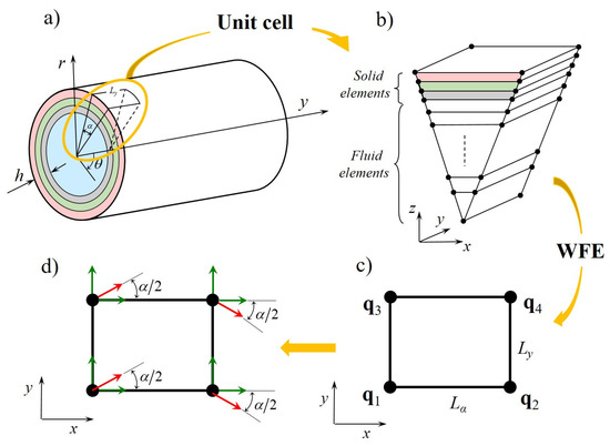
Figure 1.
(a) Schematic representation of a laminated fluid-filled cylinder; (b) FE discretisation of the arbitrary small segment of length and subtending an angle ; (c) WFE super–element; (d) rotation of the local coordinates.
The cylinder is homogeneous in the axial and circumferential directions, with an arbitrary period. Exploiting this periodicity, a very small segment of angle and length is taken, Figure 1a. The segment is then meshed by a number of elements as shown in Figure 1b, using standard FE method. The elements used depend on the nature of the structure: typically solid, 8-noded solid elements might be used to model the structure, with acoustic elements for the fluid.
The FE equations of motion of the discretised model in Figure 1b can be obtained using standard FE analysis, and vary according to the assumed field variables. The FE equation of motion in their standard, unsymmetrical formulation for acoustic FSI, when the structural and acoustic variables are the nodal displacements, , and acoustic pressures, , is
In Equation (1), the subscripts s and f refer to structure and fluid respectively, is the fluid density, , , , are mass and stiffness matrices, and are coupling submatrices, and are the nodal forces, is the viscous damping matrix for the structure, while is a dissipation term added to account for absorption of the acoustical pressure waves. Note that Equation (1) can alternatively be rewritten using acoustic potential variables for the fluid, e.g., [15].
Residual radial and hoop stresses in the structure can be found by evaluating the FE pre-stress stiffness matrix, which is then added to the original stiffness matrix. In particular, the effect of internal pressure can be modelled by the pre-stress matrix , which is obtained simply by solving a FE static analysis for a slice of the cylinder to which the internal pressure is applied. The effect of axial stress can be also considered by evaluating the pre-stress stiffness matrix, , obtained through a FE static analysis of the segment of the cylinder loaded, for example, by the axial stress
which is applied on the faces parallel to the plane. The resulting total stiffness matrix is
where is the stiffness matrix of the unloaded segment.
Assuming time-harmonic behaviour and omitting the time-dependence , Equation (1) can be rewritten in the form
where is the dynamic stiffness matrix, , where T denotes the matrix transpose, and the matrices are those of the coupled system in Equation (1), typically obtained using FE commercial software.
Following the WFE formulation in [25,27], a 4-noded super-element is formed by concatenating all the acoustical and structural degrees of freedom (DOFs) at the four corners of the prismatic segment in Figure 1c. The total vectors of the DOFs and nodal forces are ordered as
The local coordinates must be rotated as described in [25], Figure 1d. This is required to model the curvature of the cylinder and can be easily accomplished by calculating the rotation matrix ; the new FE matrices in the global system of reference become , and .
Using periodicity conditions, the relations between the nodal DOFs at the four corners are
where
Equation (6) then gives
where denotes the identity matrix. Considering internal equilibrium and periodicity conditions, the relationship between the nodal forces can be written as
Using Equations (8) and (9), the WFE reduced equation of motion becomes
and hence
where , and are the WFE reduced stiffness, mass and damping matrices whose size are , m being the total number of nodal DOFs at corner 1, Figure 1c.
For closed cylindrical structures, the number of wavelengths around the circumference must be integral and therefore the circumferential wavenumber must be an integer . It follows that
for a given circumferential mode order n. Equation (11) thus becomes an eigenvalue problem in and , whose solutions give the WFE predictions of the wavenumbers in the y direction (through ) and the wavemodes (through ). The form of the eigenproblem depends on the physical problem and on whether the frequency or the wavenumber is assumed to be real [28].
In this paper, the frequency is assumed to be real, and a quadratic eigenvalue problem in is obtained as shown in Appendix A. In particular, the eigenvalue formulation solved in this paper (to obtain the complex dispersion curves and wavemodes) is a linear companion form of the quadratic eigenvalue problem, see Equations (A3)–(A5). As a result of the 2D formulation and because of the small number of DOfs, the equation can be solved without numerical difficulties and at a very low computational cost using standard functions and routines; in the examples herein presented the function eigs in Matlab was used.
3. Numerical Examples
This section presents numerical examples. Different cylindrical structures and fluids are considered. The mass and stiffness matrices of these examples were obtained using ANSYS, exploiting its capability to model loaded and unloaded structure, fluid and FSI [29]. Once the segment is discretised, the mass and stiffness matrices are obtained from ANSYS substructuring analysis selecting all the DOFs as Master DOFs. For the sake of brevity only results for the “breathing” mode and the “bending” mode are shown. These are particularly important because fluid-borne sources may easily excite these modes, and they also play a crucial role in the vibro-acoustical behaviour of cylindrical constructions. However, results for higher order modes can be obtained without any further effort.
3.1. Water-Filled Steel Pipe
As a first example, a water-filled, isotropic, cylindrical pipe with is considered. The case is presented to validate the procedure by comparison with analytical results obtained by solving the Donnell-Mushtari equations for a thin cylindrical structure coupled with internal fluid as in [30]. At the same time, the effect of the FSI on the waves propagating in the structure is investigated. The assumptions and material properties are those used in [30]: Young’s modulus GPa, Poisson’s ratio 0.3, density kgm−3 for steel; density kgm−3 and free wave speed ms−1 for water. The FE model for this system is realised using 1 solid structural brick element (SOLID45 in ANSYS) and 20 acoustic fluid elements (FLUID30 in ANSYS), resulting in 27 DOFs after the WFE reduction. Although a single shell element could be used in this case, one solid element is preferred to avoid numerical issues related to the presence of rotational degrees of freedom.
Figure 2 shows the dispersion curves for free waves propagating in the fluid-filled pipe together with the dispersion curves for the empty cylinder, and acoustic modes in a hard-walled duct and in a soft-walled duct. In the graphs, the frequency is non-dimensionalised with respect to the ring frequency of the in vacuo shell, , while the wavenumber is non-dimensionalised with respect to R. The WFE and the analytical formulation results show good agreement.
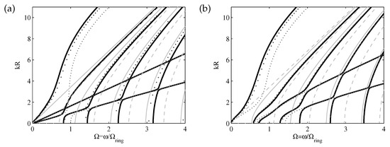
Figure 2.
Water–filled steel shell , (a) and (b) : ——– (black thick) water–filled; (thin) in vacuo; (black thick) analytic solution using the analytical equations in [30]; ——– fluid in a hard–walled duct; - - - - - fluid in a soft–walled duct.
Differences are explained considering that the analytical dispersion relation for axisymmetric and nonaxisymmetric waves was obtained using Donnell-Mushtari equations of motion for the shell. Figure 2 shows that the dispersion curves of the system are modified by the fluid-structure interaction: the presence of the fluid affects the structure’s behaviour and therefore an attempt to interpret the dispersion behaviour of the system in terms of the dispersion curves of the corresponding uncoupled subsystems, viz. an empty cylinder, fluid in a rigid duct and fluid in a soft duct, leads to incorrect conclusions. It can be noted that branches represent waves which are predominantly either structural-borne or sound-borne, with a behaviour intermediate between structural wave motion in the empty cylinder and fluid wave motion in a rigid or in a soft waveguide. It can also be noted that veering phenomena occur [31]: structural wavemodes become quasi-fluid wave modes and vice versa, giving information regarding the frequency and branches for which wave mode exchange occurs.
For , Figure 2a, branch 1 cuts-off at as an acoustical wave in a hard-walled duct and changes to a structural flexural branch as the frequency increases. The second curve represents an almost pure shear wave (fluid viscosity has been ignored and tangential motion is uncoupled from the fluid). The third curve starts propagating as a structural longitudinal wave and then becomes a fluid wave for . For , due to the increase in the radial displacement of the structure, the movements of the shell and the fluid become coupled and mode veering take place. The fourth curve starts propagating as a fluid wave; at it veers to an extensional structural wave before veering again to a fluid wave. It can be seen that higher order branches exhibit similar behaviour: close to points where the first extensional branch and acoustic branches cross, veering occurs through Poisson contraction effects and coupling between fluid and structure radial motion can be seen.
Figure 2b shows the results for the circumferential mode. A pure torsional mode uncoupled from the fluid is absent since axial, radial and tangential displacements are coupled. At high frequencies, the wave behaviour is analogous to that described for the case , while at low frequencies there are a few major variations: there is only one wave, which cuts-off as an acoustic wave and then becomes a flexural wave. A second branch cuts-off at , and is similar in nature to a pressure wave in a rigid duct for . It must be pointed out that for , all waves cut-off at frequencies different from zero, hence no wave occurs at low frequencies.
Complex dispersion curves of the water-filled steel pipe for circumferential modes and are shown in Figure 3. Characteristics of these complex dispersion curves are described in detail in [30].
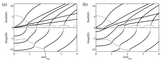
Figure 3.
Water–filled steel shell , (a) and (b) : ..... complex valued wavenumbers, ..... pure real and pure imaginary wavenumbers in the coupled system.
Cylindrical structures can be modelled accurately using thin-wall theory if and at low frequency (i.e., long wavelengths), otherwise thick-walled models are required. In order to illustrate the effect of increased thickness of the pipe, dispersion curves are shown in Figure 4 for the same water-filled pipe with and . The FE models for these pipes are implemented in ANSYS utilising two solid and twenty acoustic elements for the first case, , and five solid elements and twenty acoustic elements for the second case, . Here, for the purpose of non-dimensionalising the results, a ring frequency is defined by using the mean radius R of the cylinder in vacuo.
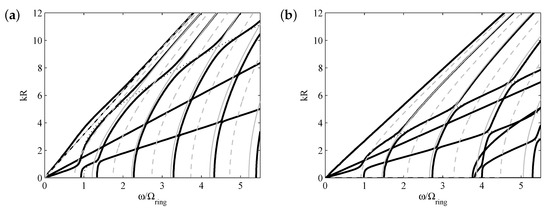
Figure 4.
Water–filled steel cylinder , (a) and (b) : ——– (black-thick) water–filled; in vacuo; ——– fluid in the hard wall duct; - - - - - fluid in the soft wall duct.
It might be expected that for increasing the pipe thickness, hence increasing the structure’s rigidity in the radial direction, the coupling would be weaker and the dispersion curves would become more similar to those for an empty cylinder and a fluid in a rigid walled duct. Figure 4 shows that this interpretation is accurate only when the wavenumber and frequency are small enough. When the wavenumber increases, coupling between acoustic and flexural waves occurs. The flexural phase velocity increases as the thickness of the cylinder increases. Hence the first branch of the empty cylinder, representing the first flexural wave, moves below the first acoustic branch and crosses higher acoustic branches. At these crossing points, strong fluid-structure coupling occurs and the branches veer. At higher frequencies, the behaviour is complicated by the cut-off of the higher order wavemodes. In particular, the second higher order branch, being extensional in nature, couples with the fluid due to radial expansion and contraction of the cylinder. Again, acoustic waves and structural waves interact through Poisson contraction effects.
3.2. Air-Filled Sandwich Cylinder
In this example, a sandwich cylinder similar to that analysed in [25] is considered but filled with air at 20C. The ratio between the thickness and the mean radius is . The structure is made of laminated graphite-epoxy skins, each comprising 4 orthotropic sheets with symmetric lay-up of , and a ROHACELL foam core. The total thickness of the skins is 2mm; the core thickness is 10mm. For this sandwich cylinder, the ring frequency is considered as the first cut-off frequency for , which has been found to be 857 Hz. The arbitrary unit cell analysed has characteristics dimensions mm and ° and it has been meshed using 12 solid elements for the skins and the foam, and 30 acoustic elements for the fluid.
The complex dispersion curves for the in vacuo and fluid-filled cylinder are shown in Figure 5. It can be seen that the dispersive behaviour is complicated by the FSI and that structural wavemodes couple with the fluid wavemodes over the whole frequency range. For the breathing mode, , this coupling clearly occurs for the flexural mode at low frequency and for the longitudinal mode at higher frequency (when the effect of Poisson contraction becomes non-negligible). For the bending mode, , acoustic curves become similar to those in a hard-walled duct, and similar to the previous case, most coupling occurs between fluid waves and structural waves that involve significant radial motion.
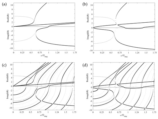
Figure 5.
Air–filled sandwich cylinder, and . (a) Fluid–filled and (b) empty: ..... complex valued wavenumbers; ..... pure real and pure imaginary wavenumbers; (c,d) ..... complex valued wavenumbers in the coupled system, ..... pure real and pure imaginary wavenumbers in the coupled system, ——– fluid in a hard–walled duct, - - - - - fluid in a soft–walled duct.
3.3. Wire-Reinforced Hard Rubber Pipe under Internal Pressure
The cylinder analysed in this section is a complex, hard rubber pipe reinforced by a helical steel wire. The procedure presented in [32,33] is here applied to take into account the helical pattern in the WFE formulation.
The ratio between the thickness and the external radius of the pipe is . The lay-up angle of the helix is . A schematic representation of the pipe structure and of the small segment taken for WFE analysis are shown in Figure 6. Both sides of the steel wire-reinforcement, denoted by 4 in Figure 6b, are filled with rubber. Three different hard rubber materials, numbered from 1 to 3, are used as depicted in Figure 6b.
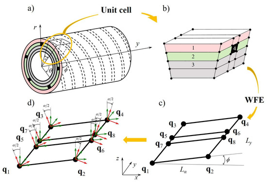
Figure 6.
(a) Schematic representation of the wire–reinforced pipe; (b) FE discretisation of a small skew segment with material properties numbered as in Table 1; (c) WFE super–element; (d) rotation of the local coordinates.
This type of cylindrical construction is used for applications such as pipes for oil transport or aircraft refuelling hoses. The specific construction might vary depending on the specific application, but typically strengthened wires are twisted around an inner synthetic rubber tube and then covered by another synthetic rubber layer. It is difficult to predict how these pipes behave mechanically, and typically several pipe specimens are experimentally tested. Although some mathematical models for these constructions have been studied, e.g., [34], developing numerical or analytical models is very difficult.
Material characteristics are given in Table 1. The size of the segment modelled for this example is: mm and 1°. The FE model of the segment in Figure 6b is realised using 30 solid elements of the type SOLID45 in ANSYS. In the following results, the wavenumber is nondimensional with respect to the internal radius of the pipe while the frequency is nondimensional with respect to calculated for E, and given by the values of material 3 in Table 1.

Table 1.
Material properties of the wire-reinforced hard rubber pipe.
Real-valued dispersion curves for circumferential orders , are shown in Figure 7. Dispersion curves obtained for the same pipe with and with no reinforcement are shown for comparison.
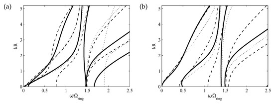
Figure 7.
Dispersion curves for the helically wire–reinforced pipe. Circumferential modes (a) , (b) : ——– helically reinforced pipe °; ........ reinforced pipe °; - - - - - non reinforced pipe.
Dispersion curves and their analysis can be used to improve the performance of these structures at a design stage. As an example, an increase in the slope of the dispersion curves generally implies increasing rigidity of the structure. The same consideration generally holds for increasing values of the cut-off frequency. Branches in the dispersion curves represent waves which are in general predominantly flexural, shear or extensional in nature. With reference to the global Cartesian coordinates in Figure 6, flexural waves involve motion primarily in the z direction while shear and extensional waves involve motion mostly in the x and y directions. However, due to the complicated construction of the pipe, the dispersive behaviour in Figure 7 cannot be described simply in terms of these torsional, extensional and flexural waves alone. Analysis of the deformation of the cross-section and the energy associated with the individual DOFs has shown that different motions are involved under the passage of a wave.
Consider the branches corresponding to the helically wire-reinforced pipe for , thick lines in Figure 7a. The first branch in Figure 7a starts propagating as a quasi-extensional wave. The cross-sectional displacement and the relative contributions of the kinetic energy in the axial (y) direction are significantly larger than those in the circumferential and radial directions. At the branch veers, involving motion primarily in the x direction, but there are also cross-sectional displacements in the y and z directions. As the frequency increases, the behaviour of branch 1 changes again, involving motion primarily in the radial (z) direction. The second branch in Figure 7a starts propagating at as a predominantly shear wave, then it veers, involving primarily extensional motion in the axial direction, and then its behaviour changes again, involving motion in both the y and x directions. Higher-order branches represent waves which are predominantly shear and extensional in nature. Generally, the behaviour is very complicated because also radial motion is involved.
Figure 7 shows that, as expected, the helical reinforced pipe exhibits a stiffer behaviour than the non-reinforced pipe, in particular in terms of extensional propagation of disturbances. Figure 7 also shows that the stiffness of the pipe depends, in different ways, on the lay angle of the reinforcing wires. At lower frequencies, the behaviour of the helically reinforced pipe () is similar to that of the circumferentially reinforced pipe (). As the frequency increases, the first branch shows that the helically reinforced pipe is less stiff with respect to flexural wave propagation. The third branch of the helically reinforced pipe has a behaviour that is intermediate between those of the circumferentially reinforced pipe and the non-reinforced pipe. Branch 4 is similar to that of the circumferentially reinforced pipe below . However, as the frequency and wavenumber increase, branch 4 and branch 5 corresponding to the case veer, due to coupling between radial and axial motion, while for branch 4 and branch 5 have almost constant phase velocities. In the frequency and wavenumber range considered, as n increases the behaviour of the helically reinforced pipe starts becoming more similar to that of the circumferentially reinforced pipe. This is particularly true for small values of the wavenumber, that is for long wavelengths, although some differences in the dispersion curves are still evident.
The presence of a high internal pressure considerably stiffens the pipe, and helical reinforcement can be used to bear the radial stress induced by internal pressure. Figure 8 shows the dispersion curves for circumferential mode orders and when the residual stress due to high internal pressure is included in the model. Dispersion curves for the same helically reinforced pipe without internal pressure are shown for comparison. It can be noticed that the internal pressure considerably stiffens the dynamic behaviour of the pipe, hence decreasing the wavenumbers. For , only the quasi-extensional wave propagates below . As the frequency increases, the pipe starts to be less stiff in the radial direction and the quasi-flexural branch cuts–off. For frequencies above , higher order branches cut-off and wavemodes involving extensional and flexural behaviour start to become coupled (consider for example the second and third branches in Figure 8a,b. The cut-off frequency of branch 4 is lower than that corresponding to branch 4 of the unpressurised pipe. It can be noticed that the behaviour of the higher order branches is not strongly affected by internal pressure. Branch 5, for example, is similar to that of the unloaded pipe. Although the internal pressure stiffens the pipe considerably, and therefore affects the wave behaviour, the behaviour of the pipe under internal pressure for shows characteristics similar to those of the unloaded pipe, Figure 8b. Again, coupling between wavemodes that involve extensional and radial motion and curve veering can be seen.
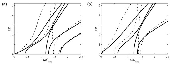
Figure 8.
Dispersion curves for the helical wire–reinforced pipe under internal pressure. Circumferential modes (a) , (b) . - - - - without pre–stress, —— with pre–stress.
4. Conclusions
In this paper the Wave Finite Element method was applied to modelling wave propagation in thick, laminated, cylinders of different construction and filled with different fluids, including pre-tensioning and residual stress effects. Compared to previous studies, the paper focused on these complicated cases, showing an alternative to other methodologies, and to the 1D formulation of the method, for the wave and vibro-acoustic characterisation of fluid-structure interaction and pre-stress effects.
In particular, the formulation proposed in the paper showed that results for any given circumferential mode order can be found without any additional investigation by specifying the circumferential wavenumber. The laminated structures were modelled using 3D solid elements, thus representing the through-thickness dynamics with high accuracy up to high frequency, but at very low computational cost, since only a very small segment of the system needs to be analysed. Therefore, the method shows promise for its implementation in optimisation processes and biomechanics research involving blood vessels, for example.
Numerical examples were presented and discussed. These concerned thick, laminated cylinders filled with water and air and a composite reinforced rubber cylinder pre-stressed by circumferential tension. It was found that an attempt to interpret the dispersion behaviour of the system in terms of the dispersion curves of the corresponding uncoupled subsystems, viz. an empty cylinder, fluid in a rigid duct and fluid in a soft duct, generally leads to incorrect conclusions, in particular when the wavenumber increases and laminated constructions are considered; in these cases, it was found that coupling and mode exchange between acoustic and elastic waves become significant. When complicated constructions with internal reinforcements and pre-stress conditions (for example due to internal pressure) are considered, it was shown that the analysis of dispersion curves could be used to investigate and improve the performance of the pipe at a design stage.
Author Contributions
Conceptualization, E.M. and B.R.M.; methodology, E.M. and B.R.M.; software, E.M. and R.G.; formal analysis, E.M.; investigation, E.M. All authors have read and agreed to the published version of the manuscript.
Funding
This research was granted by University of Parma through the action Bando di Ateneo 2021 per la ricerca co–funded by MUR–Italian Ministry of Universities and Research—D.M. 737/2021—PNR—PNRR—NextGenerationEU.
Conflicts of Interest
The authors declare no conflict of interest.
Appendix A. WFE Eigenvalue Problem
This appendix provides a brief summary of the 2D WFE eigenvalue problem formulation for axisymmetric structures. For further details, the reader can refer to [25]. If the dynamic stiffness matrix in Equation (4) is partitioned into submatrices corresponding to the super-nodes , i.e.,
then the reduced WFE eigenvalue problem in Equation (11) becomes
For closed cylindrical structures, is known for a given circumferential order n; therefore, Equation (A2) becomes, for a given , a quadratic eigenproblem in of the form
where
The standard linear companion form
is considered. Solutions of Equation (A5) yield the relationship between the wavenumber and frequency (dispersion curves) and the DoFs of the cross-section due to the passage of a wave (wave mode shapes). The obtained wavenumbers may be purely real, purely imaginary or complex. Thus the complex frequency spectrum can be determined for any given circumferential mode order. References
References
- Maio, L.; Fromme, P. On ultrasound propagation in composite laminates: Advances in numerical simulation. Prog. Aerosp. Sci. 2022, 129, 100791. [Google Scholar]
- Li, Q.; Song, J.; Shang, D. Experimental Investigation of Acoustic Propagation Characteristics in a Fluid-Filled Polyethylene Pipeline. Appl. Sci. 2019, 9, 213. [Google Scholar] [CrossRef]
- Muggleton, J.; Brennan, M.; Pinnington, R. Wavenumber prediction of waves in buried pipes for water leak detection. J. Sound Vib. 2002, 249, 939–954. [Google Scholar] [CrossRef]
- Li, X.; Xue, Y.; Li, Y.; Feng, Q. Computational Fluid Dynamic Simulation of Leakage Acoustic Waves Propagation Model for Gas Pipelines. Energies 2023, 16, 615. [Google Scholar] [CrossRef]
- Mosland, E.N.; Lohne, K.D.; Ystad, B.; Hallanger, A. Pressure Wave Velocity in Fluid-Filled Pipes with and without Deposits in the Low-Frequency Range. J. Hydraul. Eng. 2018, 144, 04018064. [Google Scholar] [CrossRef]
- Julien, T.; Faucher, V.; Pantera, L.; Ricciardi, G.; Sarrouy, E. Numerical Study of Coupled Fluid and Solid Wave Propagation Related to the Cladding Failure of a Nuclear Fuel Rod. Appl. Sci. 2022, 12, 1784. [Google Scholar] [CrossRef]
- Frecentese, S.; Papathanasiou, T.K.; Movchan, A.B.; Movchan, N.V. Movchan. Dispersion of waves and transmission–reflection in blood vessels with structured stents. Proc. R. Soc. A 2019, 475, 20180816. [Google Scholar] [CrossRef]
- van de Vosse, F.N.; Stergiopulos, N. Pulse Wave Propagation in the Arterial Tree. Annu. Rev. Fluid Mech. 2011, 43, 467–499. [Google Scholar] [CrossRef]
- Amabili, M.; Karazis, K.; Mongrain, R.; Païdoussis, M.; Cartier, R. A three-layer model for buckling of a human aortic segment under specific flow-pressure conditions. Int. J. Numer. Methods Biomed. Eng. 2012, 28, 495–512. [Google Scholar]
- Reymond, P.; Crosetto, P.; Deparis, S.; Quarteroni, A.; Stergiopulos, N. Physiological simulation of blood flow in the aorta: Comparison of hemodynamic indices as predicted by 3-D FSI, 3-D rigid wall and 1-D models. Med. Eng. Phys. 2013, 35, 784–791. [Google Scholar] [CrossRef]
- Lamb, H. On the velocity of sound in a tube, as affected by the elasticity of the walls. Manch. Lit. Philos. Soc. Mem. Proc. 1898, 42, 1–16. [Google Scholar]
- Païdoussis, M.P. Fluid Structure Interactions: Slender Structures and Axial Flow, 2nd ed.; Academic Press: London, UK, 2013. [Google Scholar]
- Zhang, X.; Liu, G.; Lam, K. Coupled vibration analysis of fluid-filled cylindrical shells using the wave propagation approach. Appl. Acoust. 2001, 62, 229–243. [Google Scholar] [CrossRef]
- Zienkiewicz, O.C.; Taylor, R.L. The Finite Element Method; Solid and Fluid Mechanics, Dynamics and Non-linearity, Volume 2, 4th ed.; McGraw-Hill: London, UK, 1991. [Google Scholar]
- Maess, M.; Wagner, N.; Gaul, L. Dispersion curves of fluid filled elastic pipes by standard FE models and eigenpath analysis. J. Sound Vib. 2006, 296, 264–276. [Google Scholar] [CrossRef]
- Everstine, G.C.; Henderson, F.M. Coupled finite element/boundary element approach for fluid–structure interaction. J. Acoust. Soc. Am. 1990, 87, 1938–1947. [Google Scholar] [CrossRef]
- Finnveden, S. Spectral finite element analysis of the vibration of straight fluid–filled pipes with flanges. J. Sound Vib. 1997, 199, 125–154. [Google Scholar] [CrossRef]
- Zheng, M.; Ma, H.; Lyu, Y.; Lu, C.; He, C. Derivation of circumferential guided waves equations for a multilayered laminate composite hollow cylinder by state-vector and Legendre polynomial hybrid formalism. Compos. Struct. 2021, 255, 112950. [Google Scholar] [CrossRef]
- Abdel-Rahman, A. Matrix Analysis of Wave Propagation In Periodic Systems. Ph.D Thesis, University of Southampton, Southampton, UK, 1979. [Google Scholar]
- Renno, J.; Manconi, E.; Mace, B.R. A Finite Element Method for Modelling Waves in Laminated Structures. Adv. Struct. Eng. 2013, 16, 61–75. [Google Scholar] [CrossRef]
- Wang, W.; Fan, Y.; Li, L. Extending Zhong-Williams scheme to solve repeated-root wave modes. J. Sound Vib. 2022, 519, 116584. [Google Scholar] [CrossRef]
- Manconi, E.; Sorokin, S.V.; Garziera, R.; Quartaroli, M.M. Free and Forced Wave Motion in a Two-Dimensional Plate with Radial Periodicity. Appl. Sci. 2021, 11, 10948. [Google Scholar] [CrossRef]
- Kingan, M.J.; Yang, Y.; Mace, B.R. Sound transmission through cylindrical structures using a wave and finite element method. Wave Motion 2019, 87, 58–74. [Google Scholar] [CrossRef]
- Nateghi, A.; Sangiuliano, L.; Claeys, C.; Deckers, E.; Pluymers, B.; Desmet, W. Design and experimental validation of a metamaterial solution for improved noise and vibration behavior of pipes. J. Sound Vib. 2019, 455, 96–117. [Google Scholar] [CrossRef]
- Manconi, E.; Mace, B.R. Wave characterization of cylindrical and curved panels using a finite element method. J. Acoust. Soc. Am. 2009, 125, 154–163. [Google Scholar] [CrossRef]
- Mencik, J.M.; Ichchou, M.N. Wave finite elements in guided elastodynamics with internal fluid. Int. J. Solids Struct. 2007, 44, 2148–2167. [Google Scholar] [CrossRef]
- Mace, B.R.; Manconi, E. Modelling wave propagation in two-dimensional structures using finite element analysis. J. Sound Vib. 2008, 318, 884–902. [Google Scholar] [CrossRef]
- Frazier, M.J.; Hussein, M.I. Generalized Bloch’s theorem for viscous metamaterials: Dispersion and effective properties based on frequencies and wavenumbers that are simultaneously complex. Comptes Rendus Phys. 2016, 17, 565–577. [Google Scholar] [CrossRef]
- ANSYS, I. Theory Reference for the Mechanical APDL and Mechanical Applications; ANSYS, Inc.: Canonsburg, PA, USA, 2016. [Google Scholar]
- Fuller, C.R.; Fahy, F.J. Characteristics of wave propagation and energy distributions in cylindrical elastic shells filled with fluid. J. Sound Vib. 1982, 81, 501–518. [Google Scholar] [CrossRef]
- Mace, B.R.; Manconi, E. Wave motion and dispersion phenomena: Veering, locking and strong coupling effects. J. Acoust. Soc. Am. 2012, 131, 1015–1028. [Google Scholar] [CrossRef]
- Sorokin, S.; Manconi, E.; Ledet, L.; Garziera, R. Wave propagation in helically orthotropic elastic cylindrical shells and lattices. Int. J. Solids Struct. 2019, 170, 11–21. [Google Scholar] [CrossRef]
- Manconi, E.; Sorokin, S.; Garziera, R.; Soe-Knudsen, A. Wave Motion and Stop-Bands in Pipes with Helical Characteristics Using Wave Finite Element Analysis. J. Appl. Comput. Mech. 2018, 4, 420–428. [Google Scholar]
- Evans, J.J.; Wilcox, P.D. A structural model for high pressure helical wire–wound thermoplastic hose. Acta Mech. 2002, 39, 1307–1326. [Google Scholar] [CrossRef]


Disclaimer/Publisher’s Note: The statements, opinions and data contained in all publications are solely those of the individual author(s) and contributor(s) and not of MDPI and/or the editor(s). MDPI and/or the editor(s) disclaim responsibility for any injury to people or property resulting from any ideas, methods, instructions or products referred to in the content. |
© 2023 by the authors. Licensee MDPI, Basel, Switzerland. This article is an open access article distributed under the terms and conditions of the Creative Commons Attribution (CC BY) license (https://creativecommons.org/licenses/by/4.0/).