Article

Design and Verification of a Large-Scaled Flapping-Wing Aircraft Named “Cloud Owl”

1
School of Aeronautics, Northwestern Polytechnical University, Xi’an 710072, China
2
Research & Development Institute of Northwestern Polytechnical University in Shenzhen, Shenzhen 518057, China
3
Yangtze River Delta Research Institute of Northwestern Polytechnical University, Taicang 215400, China
*
Author to whom correspondence should be addressed.
Appl. Sci. 2023, 13(9), 5667; https://doi.org/10.3390/app13095667
Submission received: 10 April 2023 / Revised: 28 April 2023 / Accepted: 30 April 2023 / Published: 4 May 2023
(This article belongs to the Section Aerospace Science and Engineering)

Abstract

:
The bionic flapping-wing aircraft has the advantages of high flexibility and strong concealment; however, in the existing flapping-wing aircraft, the platform performance is influenced by the payload capacity, endurance, and durability; additionally, the mission capability is constrained, making it challenging to put into use in real-world scenarios. In response to this issue, this article offers a thorough design approach for a large-span flapping-wing aircraft, focusing on effective flapping wings, effective flapping mechanism design, and enhancement of flapping mechanism reliability, and ultimately realizing the design and verification of a new bionic flapping-wing aircraft with a large wingspan, called “Cloud Owl”. It has a wingspan of 1.82 m and weighs 980 g. The aircraft is capable of autonomous flight and remote control, and it can carry a range of mission-specific equipment. More than 200 flights have been made by “Cloud Owl” so far in Xi’an, Beijing, Tianjin, Tibet, Ganzi, and other places. It has evolved into a flapping-wing aircraft platform with exceptional stability, payload capacity, and long endurance.

1. Introduction

Prior to recently, the majority of research on flapping-wing aircraft was concentrated in the area of small and micro-planes. Micro flapping wing vehicles can function in small locations and have excellent flying efficiency, but their short endurance and low payload capacity are their main drawbacks [1,2]. The large-scale bionic flapping-wing aircraft may thus satisfy the needs of long-range, long-endurance flight as well as high-efficiency, low-speed cruise flight.
Several large-wing flapping-wing aircraft are shown in Figure 1. The Smart-bird [3,4] has a wingspan of 2 m, a weight of 0.48 kg, a flight speed of 5 m/s, and a flapping frequency of 2 Hz; however, even though it has good low-speed flight stability and gliding performance, its load-carrying capacity and endurance are currently unknown. The “Robo raven” [5,6] has a wingspan of 1.168 m, a weight of 290.3 g, a flight speed of about 6.7 m/s, and a flapping frequency of 4 Hz; the falcon [7] has a wingspan of 1.2 m, a total weight of 600 g, a flight speed of 8 m/s, a flapping frequency of 3.5 Hz, and can carry a total weight of 16.7% of the payload for a 20-min flight. The “HIT-Hawk” and the “Hit-phoenix” [8,9,10] had wingspans of 2.0 m and 2.3 m, weights of 792 g and 675 g, respectively, and maximum take-off weights of 1.15 kg and 0.86 kg, respectively, with no-load maximum stable flight endurances of 65 min and 8 min, respectively.
By comparing the performance parameters of large wingspan (>1 m) aircraft both at home and abroad, the longest non-load flight endurance is 65 min, the flight endurance is shorter when carrying a payload, the fastest flight speed is 8 m/s, and most aircraft cannot perform autonomous flights. From a practical standpoint, there is still a significant gap [11,12,13]. The large-winged bionic aircraft still has much room for growth in terms of payload capacity, flight endurance, and flight speed.
In this article, a flapping-wing aircraft called “Cloud Owl” is designed in response to the above challenges. The flapping-wing aircraft has the following features: high payload capacity, long endurance, complete electronic equipment, autonomous flight, optimization for the plateau environment, and the capability of performing a variety of flight missions. As an aircraft platform, it can satisfy the following requirements: (1) It can carry out remote control flight and autonomous flight and has onboard information perception and real-time mission planning capabilities; (2) high payload capacity, The total weight of the no-load is 980 g, and it can carry a payload of 320 g, which is enough to carry equipment such as a three-light pod, a mapping camera, a panning camera, and so on. (3) Long endurance capability: the longest endurance without payload is up to 154 min, and the longest range can reach 60 km while speed is between 6 m/s and 8 m/s. (4) High-altitude adaptability: Flapping wings are designed to be very adaptable to high-altitude conditions. After flight testing, the Cloud Owl can still fly effectively at 4500 m above sea level. (5) High dependability: The flapping mechanism has undergone more than 200 iterations and improvements, and it has an onboard flying life of more than 400 min.
The basic parameters are shown in Table 1.
This article also provides a novel design method for a flapping-wing vehicle with a large wingspan, which is verified by the prototype test. The technical advancement is in (A) The preliminary estimation of the overall parameters can be done using the biological scale of flight and the parameter correction approach suggested in this article. (B) Adaptive optimization method for flapping-wing at high altitude to provide a reference for flapping-wing design at high altitude; (C) Dependability growth test for flapping mechanism can extend the life effectively; (D) Following flight testing and system debugging, integrated flight control improvement was made to finish the design of a stable and lightweight flight control system; and (E) The whole aircraft modular design, fuselage, tail wing, mechanism, flapping-wing, battery, etc. are all individually made components that can be quickly installed and replaced. Finally, the Cloud Owl is a stable and controllable flapping-wing aircraft with a huge wingspan and good payload capabilities, as demonstrated by more than 200 flight tests conducted in various locations with various payloads. The design approach might offer technical direction for the same class of flapping-wing air vehicles.
The article is divided into three main sections. The first section introduces the Cloud Owl design process, which is divided into general design, wing design, mechanism design, power and energy system design, avionics system design, subsystem integration test, and iterative optimization. The flight tests are presented in the second section, and the article is summarized in the final paragraph. The design process is displayed in Figure 2.

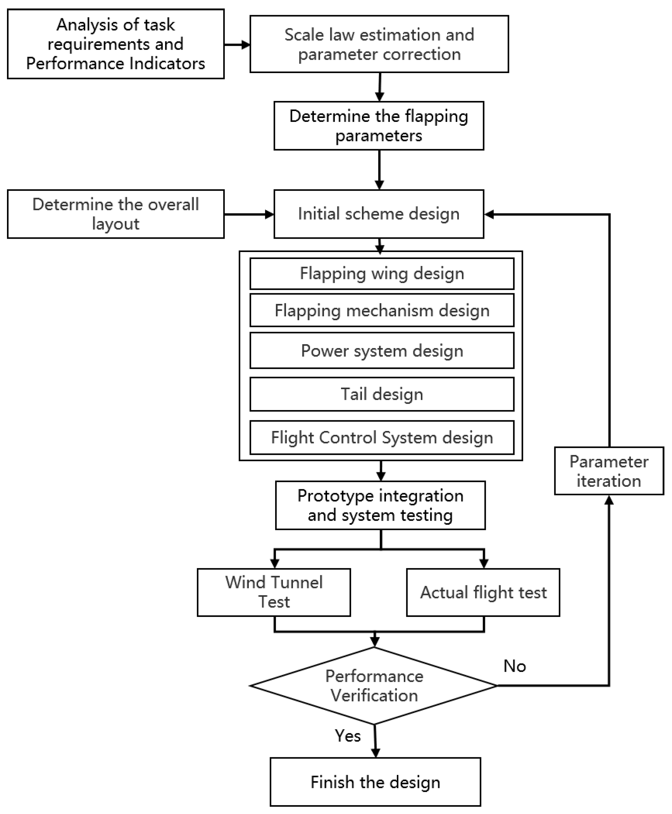
2. Materials and Methods

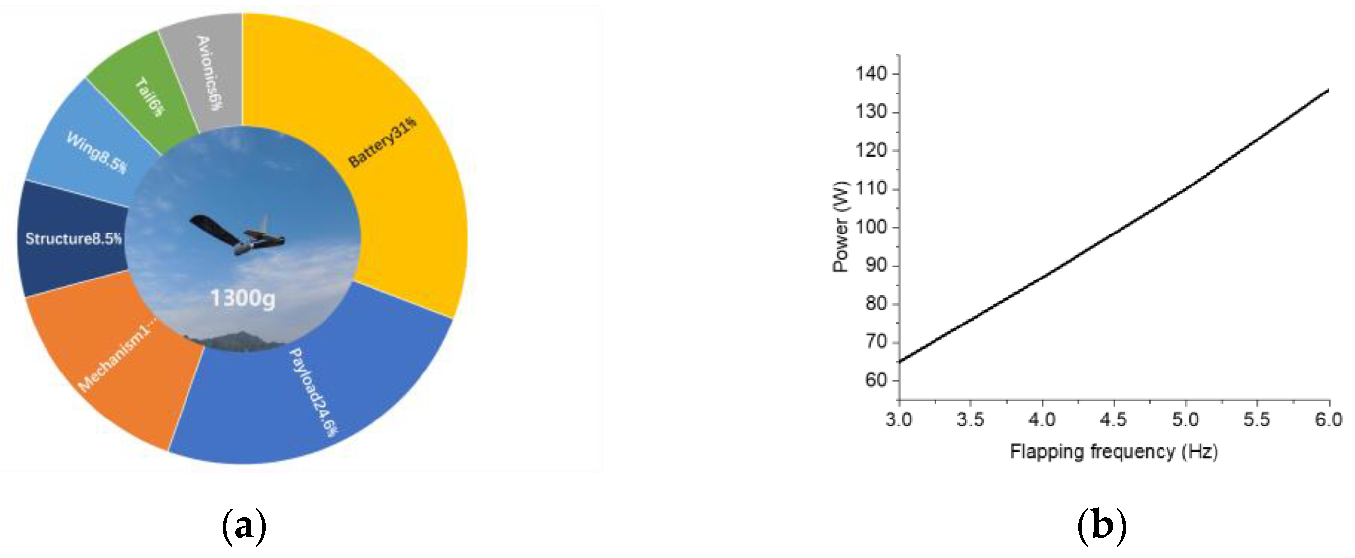
2.1. Overall Layout and Weight Estimation
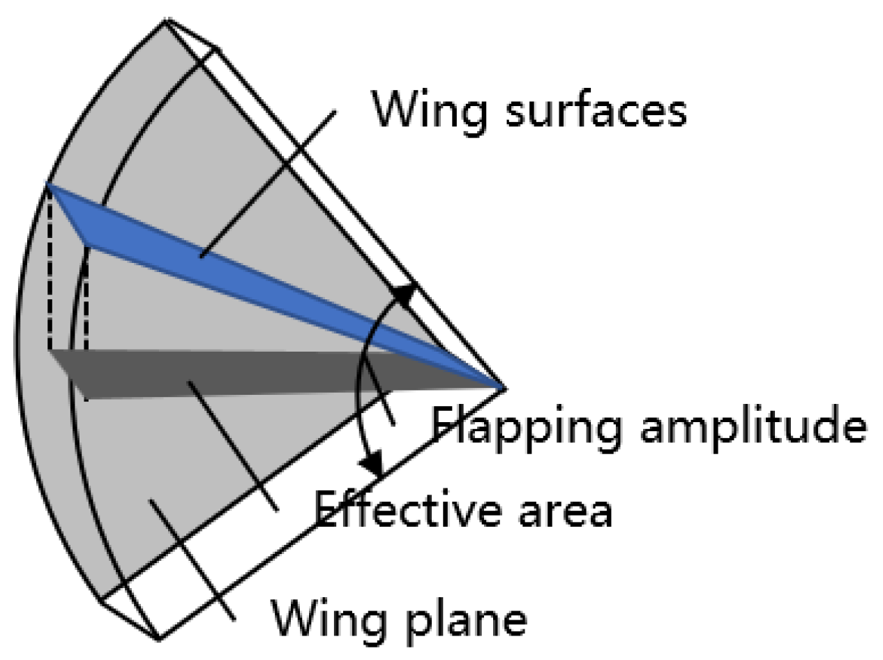
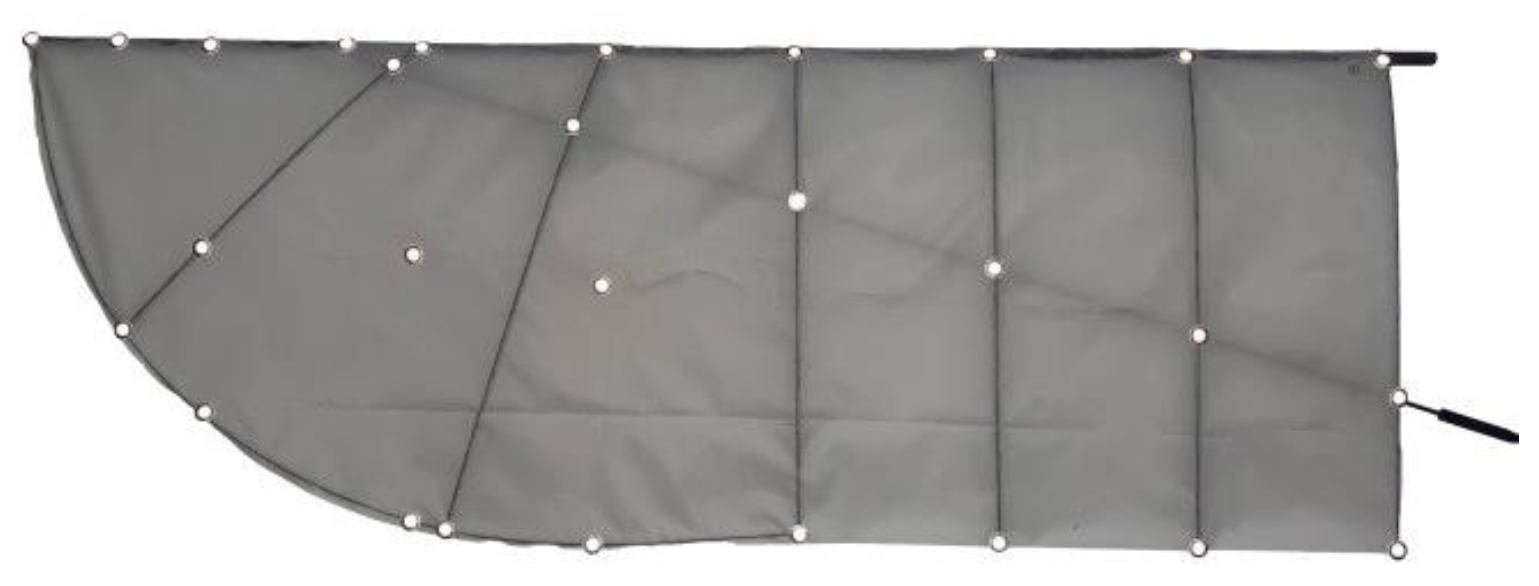
The Cloud Owl uses an up-and-down flapping mode and a flexible wing structure to achieve passive deformation of the chord and spreading directions, simulating the active and passive deformation of the wing during the bird’s flapping motion. The lifting ailerons are placed on the trailing edge of the inverted t-shaped tail, which was chosen as the tail configuration. The benefit of this configuration is that it has high static stability characteristics for the heading and longitudinal separation, making it easy to realize attitude control. The mechanism is in front of the flapping-wing aircraft, the battery is on the trailing edge of the wing, the electronic equipment is fixed in the middle of the fuselage, and the payload is in the head of the fuselage, as shown in Figure 3.
The takeoff weight of the aircraft can be roughly divided into five parts: the fuselage structure weight WS1, which includes the fuselage shell and internal structure; the aerodynamic structure weight WS2, which includes flapping wings and tail wings; the drive system weight WP, which includes a reduction gear set, a brushless DC motor, a crank rocker, as well as other transmission parts and batteries; the electronic equipment weight WE (including the flight control system, GPS, data transmission, image transmission, receiver, airspeed meter, pitot tube, governor, etc.); and the payload weight WM, namely WTO = WS1 + WS2 + WP + WE + WM.
The chosen materials and an approximate weight estimate are provided in Table 2 with reference to the team’s mature aircraft, “Dove” [14].

2.2. Wing Design

Flapping wings are the key component of flapping-wing aircraft. The lift and thrust of a flapping wing are intimately correlated with its shape, motion, and structural stiffness.
The structural parameters, motion parameters, and dynamic parameters of flapping-wing vehicles are typically estimated by the bionic scaling rate [15]. The initial take-off weight of these vehicles is 1310 g, and the scale rate calculation is used to determine the overall parameters, which are fitted by the exponential function k × mp, as shown in Table 3.
The computation of the flapping amplitude, which can be done using the Strouhal number similarity principle, is not required by the scale law. To account for both thrust and propulsion efficiency, St is set at 0.3 [16]. The following formula yields the calculated flapping amplitude of 63.7°.
φ = 2 arcsin ( S t × V ÷ f ÷ b )
The results of wind tunnel measurements show that, under the assumption that average angular velocities are similar [17], the aerodynamic properties of flapping wings are similar and independent of variations in flapping amplitude and frequency. The scale rate calculation results show that the flapping frequency is lower but the flapping amplitude is higher, which is counterproductive to increasing cruise speed. As a result, the flapping frequency and amplitude should be adjusted in accordance with the cycle’s average angular velocity. The flapping amplitude was calculated to be 43.8°, and the flapping frequency was changed to 5.5 Hz. The following formula, where A is the amplitude of the flapping, yields the mean periodic angular velocity.
ω ¯ = 1 T 0 x | ω f l a p | d t = 2 A f
The actual wing surface area Se is a dimensionless reference region that has more reference value because it has nothing to do with the law of flapping. These parameters are displayed in Figure 4.
S e = f 0 1 f S cos ( φ sin ( 2 π f t ) ) d t
F stands for the flapping frequency (Hz), S is the area of the wing (m2), φ is the flapping amplitude (°), and T is any point in the flapping period.
Due to the fact that flapping-wing vehicles share some characteristics with both rotorcraft and fixed-wing aircraft, the following is the definition of the wing load of a flapping-wing aircraft:
Q = W TO S n = W TO S e × W TO S P
The equivalent wing area, Sn, in the formula, is equal to the square root of the product of Se of the effective wing area and SP of the wing disk area. SP is the disk area; Sp = 2πb2φ/360, where b is half of the wingspan. WTO/Se is known as normal wing load, and WTO/Sp is referred to as tangential wing load.
The term “normal wing load” has the same definition as “wing load” for fixed-wing aircraft. It is an essential factor in determining how well flapping-wing micro air vehicles perform in the stall, climb, take-off, and landing phases, as well as during hovering. The tangential wing load is an important parameter to characterize the size and flapping range, acceleration and deceleration performance, and residual power of flapping-wing micro air vehicles. The parameter Q thus represents the dual capacity of the flapping-wing vehicle in the lift direction and thrust direction, which can be called an equivalent wing load due to the use of the equivalent wing area.
In the results of the scale law calculation, the flapping wingspan and the flapping wing area are small, and the equivalent wing load is large, which is not conducive to improving the flight time, so the flapping wing area should be appropriately increased to reduce the wing load. The initial half of the wingspan is 0.8 m.
The design procedure goes as follows: the wing area is estimated using the dynamic equation of the cruise state, the flight speed is temporarily set to 8 m/s, and the initial parameters of the wing can be determined. Next, the wing shape and flapping parameters were optimized using the CFD method, and the best flapping parameters were ultimately determined by combining this with wind tunnel testing. The design procedure is displayed in Figure 5.
The investigation of transient simulations is conducted by resolving the three-dimensional Navier-Sir George Stokes 1st Bar-one equations and utilizing the computational fluid dynamics program Fluent [18,19,20,21]. Based on an overlapping grid approach, the motion of a flapping wing is reproduced. The backdrop grid and component grid that make up the overlapped grid are appropriate for simulating large-scale motion. The backdrop grid does not move during dynamic movement; instead, the entire component grid moves as a rigid body. By adjusting the function’s user-defined coordinate transformation form in order to vary the wing-flapping motion. The mesh around the wing in the deformable zone is updated using the dynamic mesh technique as the wing moves. The calculation’s airfoil model mimics the actual flapping wing’s airfoil and plane form. The wing is taken to be a rigid body whose only motion is rotation about the x-axis in order to streamline the model and speed up numerical convergence. Using user-defined functions (UDF), wing trajectories with rotation (i.e., flapping amplitude and frequency) are implemented. The impact of wing morphology parameters can be investigated via CFD calculations and wind tunnel tests.
The base airfoil, Eppler 378, has the geometric characteristics of the cross section of a bird’s wing, which is displayed in Figure 6. It has good aerodynamic performance, which is obviously high lift with minimal resistance.
The design factors for flapping wings are as follows: wing forms; six or seven wing ribs; polyester or linen film; additional airfoil or not. According to the four design variables, thirteen different flapping wings were created and tested in a wind tunnel.
Literature [22] can be consulted to learn more about the method and outcomes of CFD calculations and wind tunnel tests. The flapping wing was chosen for its original plane shape, flax film material, six ribs, half wingspan of 0.8 m, two wing areas of 0.426 m2, and no additional airfoil wing, based on the results of CFD calculations, wind tunnel experiments, and the actual weight of the flapping wing. The wing has a payload capacity of more than 300 g and weighs 110 g, which is displayed in Figure 7.

2.3. Tail Design

The length of the flat tail was calculated using the vortex lattice method’s XFLR5 aerodynamic calculation and longitudinal trim for the gliding condition. The flapping wing was changed to a rectangular wing of the same size, and the flat tail airfoil was changed to one with the NACA0006 instead of the flat profile. The calculation model and outcomes are displayed in Figure 8.
The dimensions of the tail are 500 mm for the horizontal tail, 250 mm for the outer chord, 350 mm for the inner chord, 250 mm for the vertical tail, and −4° for the angle at which the tail is installed. According to the calculations, the flat tail capacity is 0.76, the vertical tail capacity is 0.38, the trim angle of attack is 8°, and the center of gravity is about 15 cm from the front end of the fixed location of the wing trailing edge.
The wind tunnel tests are conducted with a flapping wing and tail wing, and the curve of lift and thrust varies with velocity are shown in Figure 9. The angle of attack is 8°, and the frequency of flapping is 4 Hz. Accordingly, under these circumstances, the lift of the flapping wing can reach 1300 g.

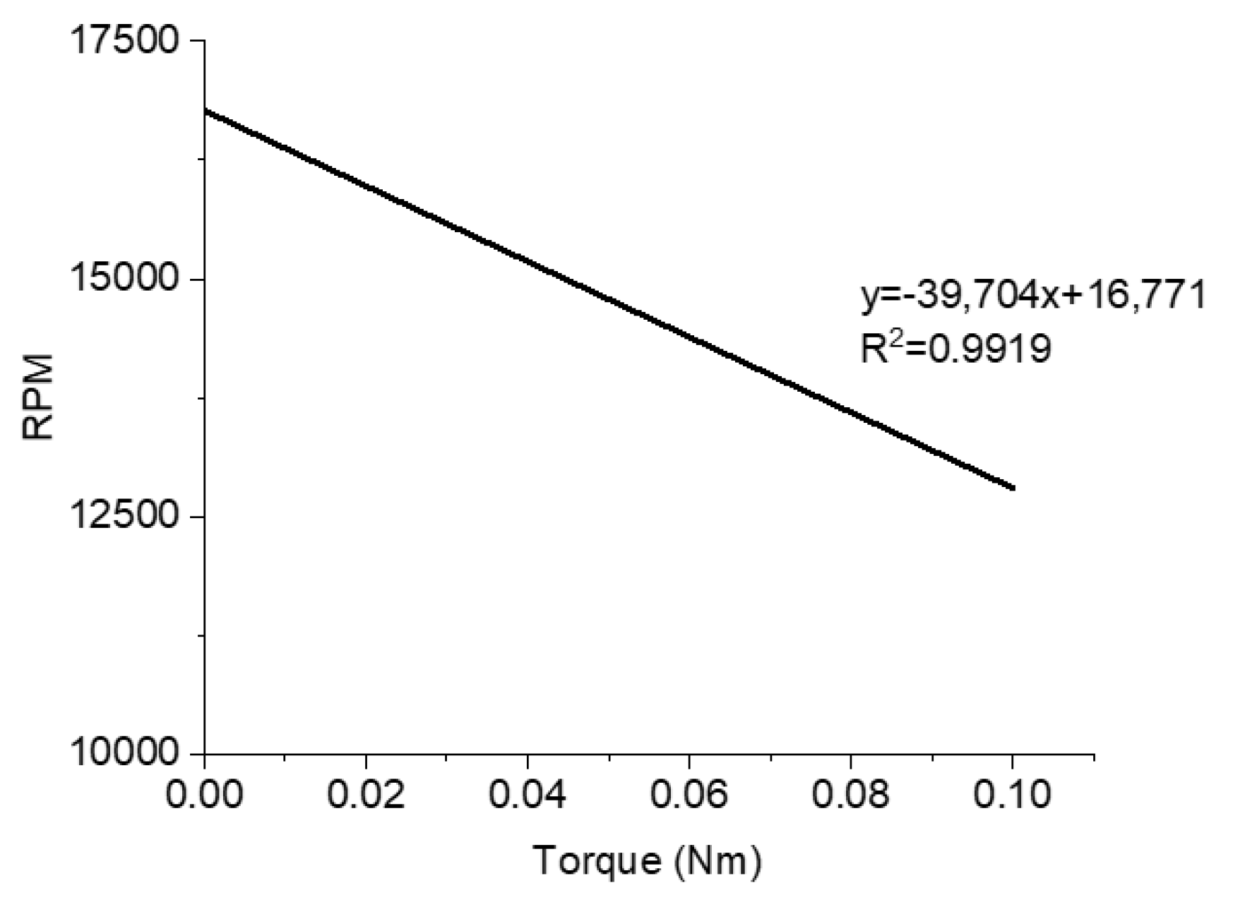
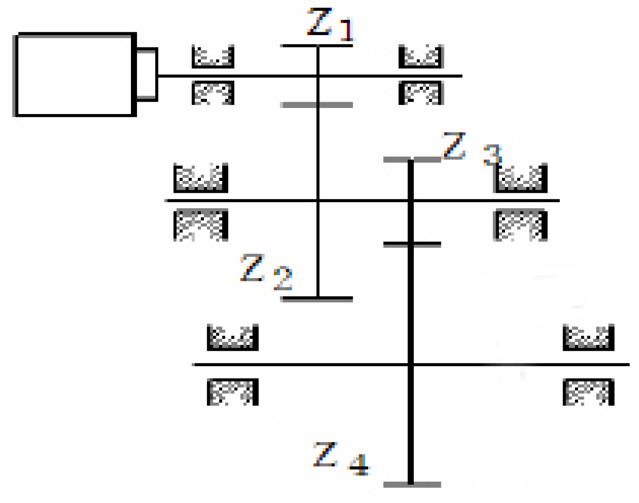
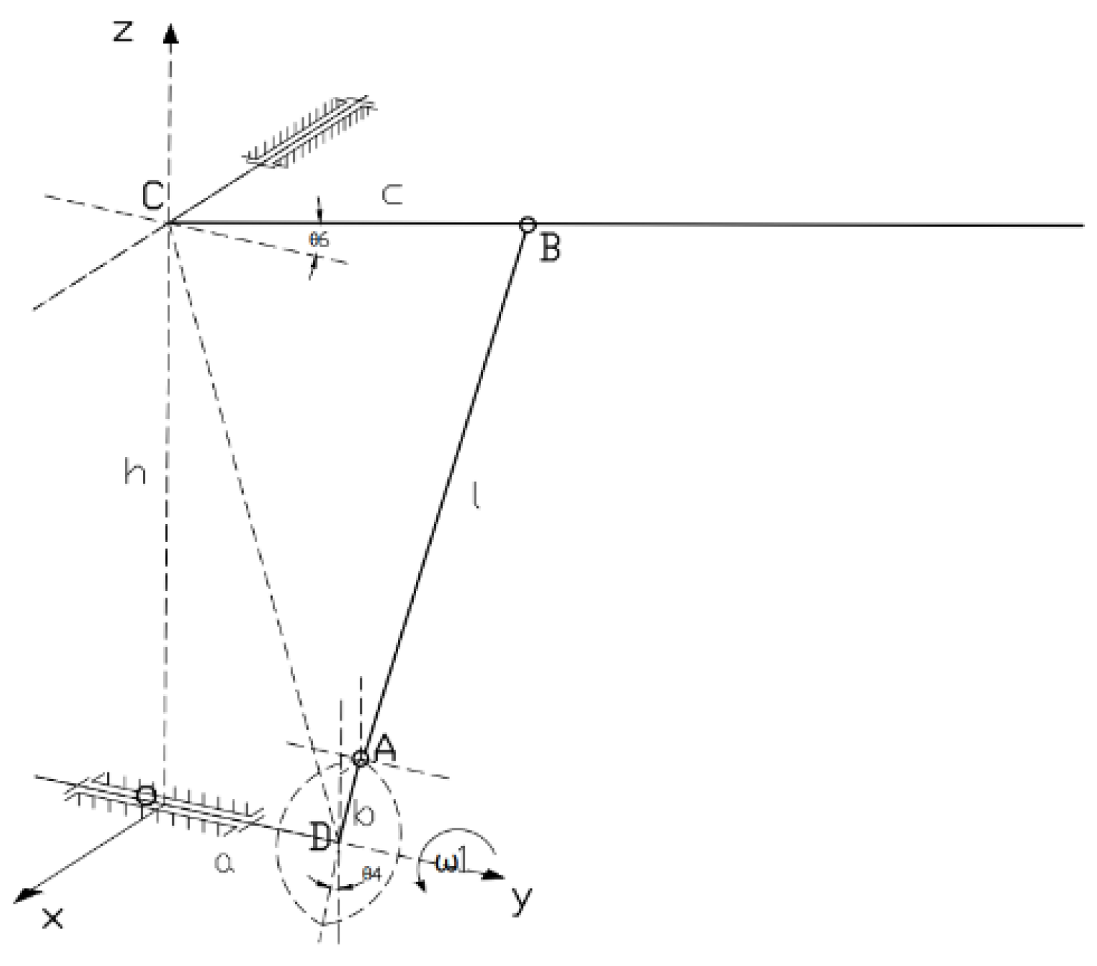
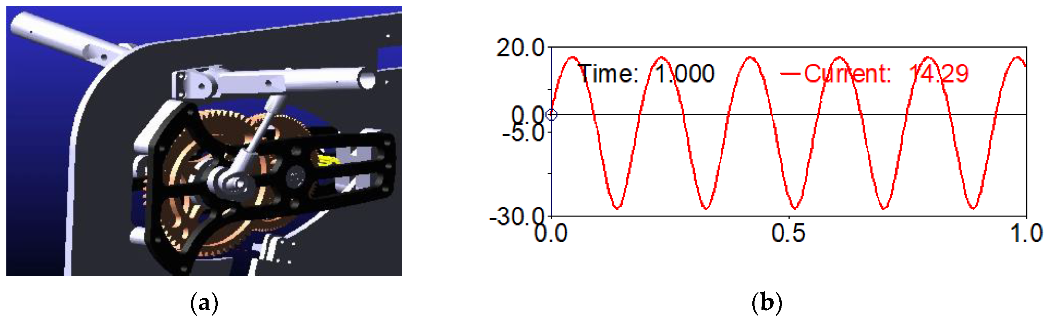
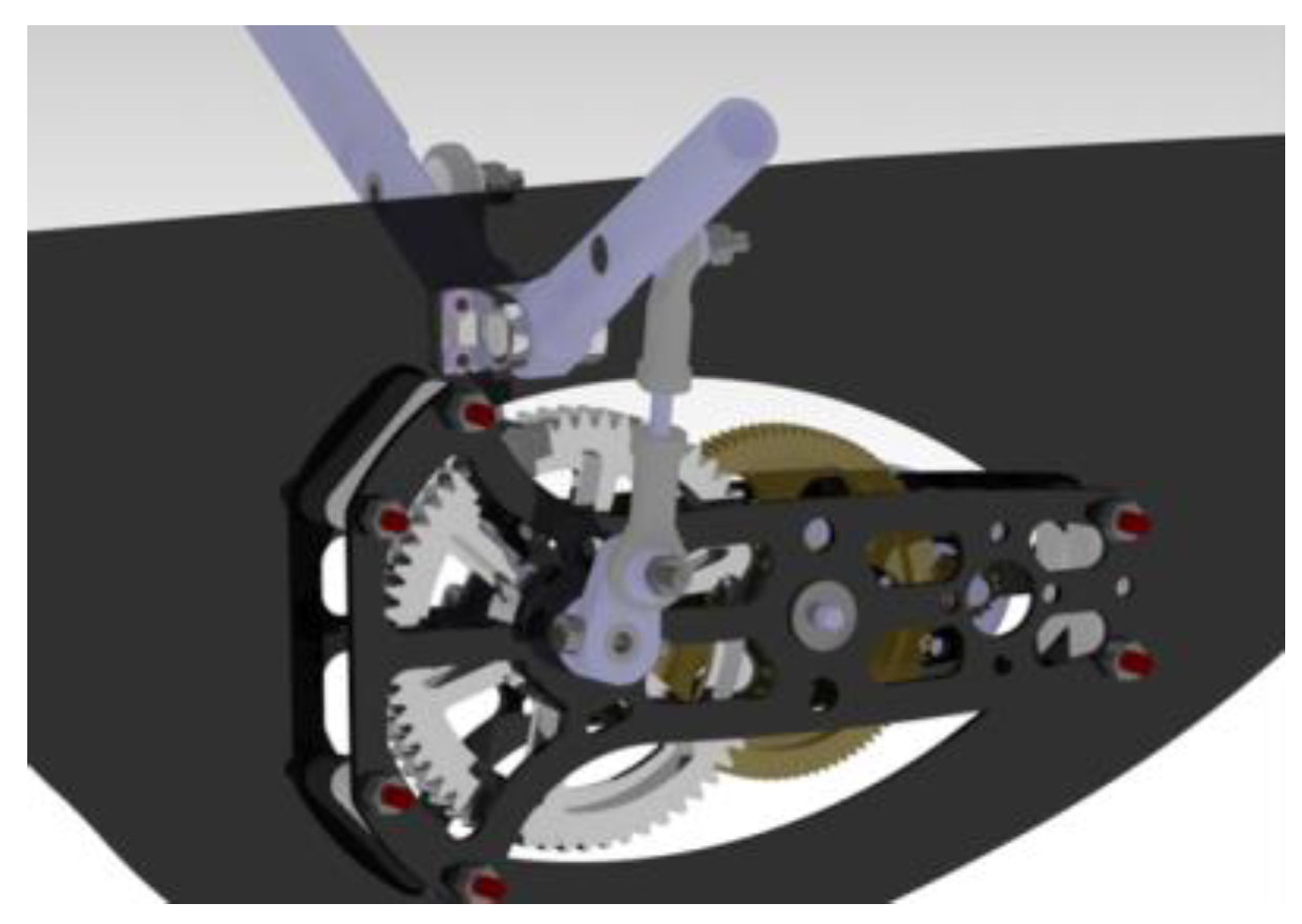
2.4. Power System Design

A flapping-wing aircraft’s flapping wing produces lift and thrust, and the drive mechanism, which is directly attached to the flapping wing and controls its movement, including its frequency, amplitude, and other characteristics, does the same. The drive mechanism must output adequate torque to the flapping wing in order for the flapping wing to generate enough lift for the aircraft to fly normally.
In the conceptual design stage, there are no detailed design parameters of the driving mechanism, so it is challenging to directly acquire the instantaneous flapping angular velocity in the conceptual design stage in order to calculate the average periodic angular velocity. The common flapping-wing drive mechanism is the crank-connecting rod mechanism, and the motion equation of its output is close to the sine function, so it is advisable to set the motion equation of the instantaneous flapping angular displacement of the output end of the drive mechanism as the form of the sine function shown in the equation. The corresponding instantaneous flapping angular velocity is obtained by taking the derivative.
θ f l a p = A 2 s i n ( 2 π f t )
ω f l a p = θ f l a p = π A f c o s ( 2 π f t )
In the formula, θflap stands for the instantaneous flapping angular displacement; ωflap is the instantaneous flapping angular velocity; A is the flapping amplitude; and f is the flapping frequency.
In the cruise state, the weight of the aircraft is assumed to be the lift produced by the flapping wings, and the maximum cruise power and output torque of the drive mechanism are determined on the assumption that the wingspan is known [23].
F L = W t o g
T wingmax = F L b 4
P wing   max = T wing   max ω f l a p m a x
P m o t o r = P w i n g m a x η t r a n s
P m o t o r m a x = P m o t o r η m o t o r
In the formula, ηtrans is the mechanical efficiency of the driving system and ηmotor is the motor efficiency.
The drive system is driven by a micro brushless motor. For the two stages, the mechanical transmission efficiency is about 81%. The maximum output power of the motor is 104 W. At the same time, the battery capacity is 10.8 AH according to the designed target endurance of 100 min after getting the maximum cruising power. Table 4 lists the optional motor models.
In each level, the motor with the lower KV value should be chosen in consideration of the lower flapping frequency. After taking the installation mode, weight, and output power requirements into account, the 2312 motor (KV1400) is chosen.
The AT2312 motor is tested, and the relationship between motor speed n and motor output torque T is determined by fitting data points in Figure 10.
n m = 39 , 704 T m + 16 , 771
The reduction ratio must be satisfied in order to meet the maximum flapping frequency requirements of f = 6 Hz.
i n m 60 f
The torque necessary to propel the flapping wing, according to a conservative estimate, which is the reduction ratio must meet the requirement of a factor of safety k = 1.5.
i k T o u t T m η
In the formula, f stands for flapping frequency; Tm is the output torque of the motor; ηtrans the mechanical efficiency of the drive system.
The viable region of the reduction ratio along with the frequency and torque constraints is displayed in Figure 11. The point in the upper left corner of the practicable zone is chosen, and the reduction ratio is i = 37. This is because the motor’s efficiency is typically higher when the output torque is low.
The reducer has a parallel gear configuration (as depicted in the diagram), which has a straightforward structure and can increase engineering viability and dependability. The gear set of the flapping mechanism is displayed in Figure 12.
Given its strength, speed, and smoothness, it can withstand a brief overload. The diameter of the first stage big gear and crank output shaft do not interfere, the low-speed class’s modulus cannot be less than that of the high-speed class’s, the pinion root circle’s size cannot be smaller than the motor pivot, and so on. From these factors, the design parameters of the reducer can be determined.
M1 = 0.5, M2 = 1, Z1 = 15, Z2 = 99, Z3 = 11, Z4 = 61, and I = 37. Where M1, and M2, represent the modules of gears for the high and low speed classes, respectively; Z1, and Z3, are the number of pinion teeth for the high and low speed classes, respectively; and I1 is the gear ratio for the high-speed class.
The mechanism adopts the spatial crank rocker configuration scheme, which has the advantages of a simple structure, few parts, high efficiency, and high dependability [24,25]. The schematic of the spatial crank-rocker four-bar linkage is displayed in Figure 13.
As shown, Rod AD, AB, BC, and CD form a four-bar linkage on one side, where Rod AB is connected by a ball joint, Rod BC moves in the YZ plane, and Rod AD moves in a plane parallel to the XZ plane. The Rod AD is rotating at an angular velocity, which is the angle at which it turns. Then the length of the AB rod can be expressed.
( b sin θ 4 ) 2 + ( c cos θ 6 a ) 2 + ( h + c sin θ 6 b cos θ 4 ) 2 = l 2
The upper and lower limit positions of Bar BC correspond, respectively, to the upper and lower limit positions of Bar AD. From the specific size of the reducer, H = 44 mm, a = 12 mm, and C = 35 mm. From the equation of motion, the values of B and l are calculated according to the set angle, as indicated in Table 5. The final design parameters are listed below.
The preliminary kinematic analysis is then performed, primarily to assess interference by comparing the measured flapping frequency and amplitude to theoretical calculations, which is displayed in Figure 14.
The flapping amplitude is about 45°, which satisfies the design requirements.
The completed mechanism is depicted in Figure 15. In this article, the issue of mechanism failure brought on by the wear of the connecting rod, gear, and other essential components of the existing flapping-wing drive mechanism is studied. By analyzing the causes of wear, the structural design of the driving mechanism is improved, and the improved effect is confirmed by an actual ground bench test.
During the test, the input and output parameters of the driving mechanism are kept as certain as possible. The experimental conditions are provided in Table 6. After 55 min of cyclic loading, the failure time and the failure condition were recorded after using the parts without optimization at first, recording the failure time, and then using the parts with optimization. The experiment duration and failure times were then plotted using the data that had been collected. The ground test bench for flapping mechanism and experimental data of flapping mechanism are displayed in Figure 16.
The cumulative test time is plotted on the horizontal axis as part of the reliability growth trend test of the test failure data. The longitudinal axis is the cumulative failure number, as shown in the graph. The first four hours or so of the experiment represent the mechanism before the improvement; the curve of this section is concave, the time between adjacent faults is getting smaller, and the reliability is starting to decline. The result demonstrates that the dependability of the mechanism before the improvement is insufficient, but after the optimized parts are replaced, the segment’s curve is upwardly convex after 5 h, and the distance between adjacent faults is longer. The mechanism wears out after 20 h; the noise increases, but the flight is unaffected. This indicates that the mechanism is now more dependable.
The test procedure is to fly to the designated altitude after takeoff (carrying a 200 g payload) and then enter the mission mode to fly in a circle. After numerous flights, after 400 min of flight of the mechanism as shown in Figure 17. There is some gear wear that still does not affect the flight. It can be seen that the life of the improved mechanism has been significantly increased.
The output power of the regulated power supply at the same wind speed and flapping conditions is mostly used to compare the power consumption before and after the drive mechanism development. The work power of the improved mechanism was reduced by 12 W as a result of the improved driving mechanism parts’ increased strength, assembly accuracy, and efficiency during the test, when the output voltage of the power supply was fixed at 15 V and the average output current of the improved power supply was 8 a and 7.2 a, respectively.

2.5. Avionics of the Cloud Owl

“Cloud Owl” primarily uses its wings to provide lift and propulsion, and it adjusts the elevons to manage the aircraft’s pitch and roll attitude. Without real-time control of the lightweight flight control system, which consists of a flight control panel, a galvanometer, a governor, GPS, airspeed, a receiver, and data transfer, stable autonomous flying cannot be performed. The flight control panel includes an integrated IMU (inertial measurement unit) and AHRS. The electronic apparatus is 80 g in weight. The PX4 firmware is utilized as the primary flight control system, while the flight control hardware is based on Pixhawk. The aircraft’s flight attitude and mode can be adjusted in conjunction with the ground station, and real-time digital transmission communication is also possible. The avionics of the Cloud Owl are shown in Figure 18.

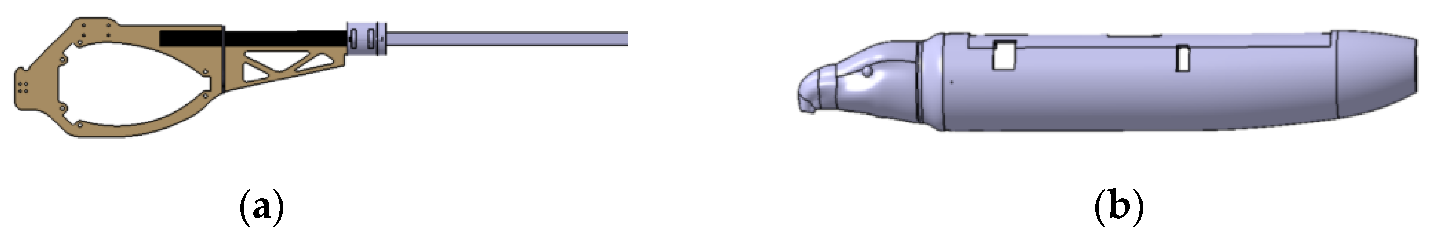
2.6. The Fuselage of the Cloud Owl

In the design process, the main considerations of strength while minimizing weight, the use of overall carbon fiber composite components, and parts of the connector made using 3D printing are all part of the fuselage design. The fuselage design includes the fuselage shell design and the internal frame design. The internal frame plays the fixed mechanism, the wing, the electronic equipment, the battery, and the tail wing functions. Made of EPP foam, the fuselage shell’s primary function is to protect the inside structure. The fuselage of the Cloud Owl are shown in Figure 19.

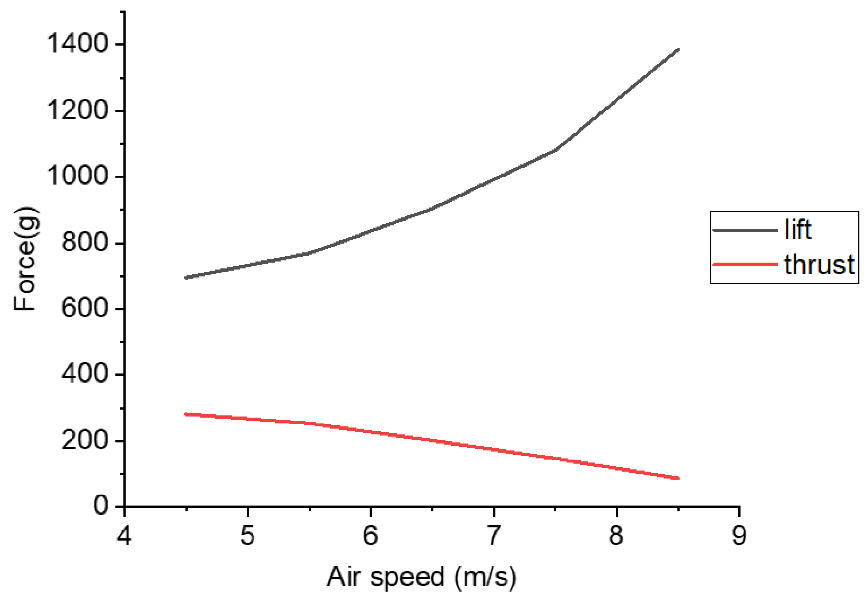
3. Results and Discussion

The flight test is conducted in this section, comprising the autonomous flight test, the payload capacity test, and the flight test with different payloads.

3.1. Prototype Integration and Flight Test

The system weighs 980 g without payload and is mostly made up of the mechanism, electronic components, battery, wings, and tail wings. When carrying a 320 g payload, the cruise power is roughly 87 W, and the frequency of flapping is 4 Hz, as determined by the power module installed in the aircraft. The mass distribution and the power distribution at various frequencies are displayed in Figure 20, Figure 21, Figure 22, Figure 23 and Figure 24.

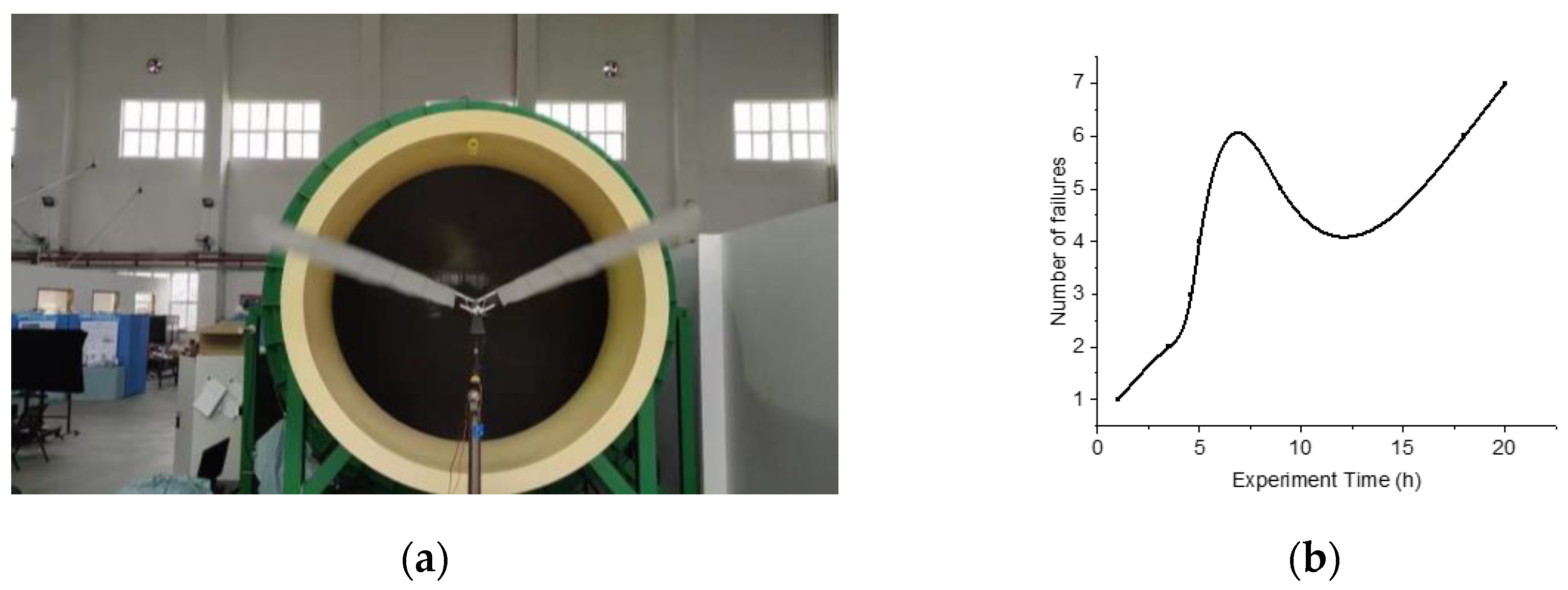
3.2. Payload Capacity Test

During the flight, the flight data is also recorded. The design is strong enough to fly in a range of settings, from plain to high altitude, as demonstrated by more than 200 flight tests.
As a large-winged flapping-wing aircraft with high payload capacity, the Cloud Owl can achieve stable autonomous flight. Many tests with payloads have been carried out in the Xi’an area and the plateau area (4200 m above sea level). The flight performance of plains and plateaus which contains the power consumption, frequency of flapping, and flight speed for the flight experiments with payloads ranging from 980 g to 1500 g using the same battery, can be seen in Figure 21.

3.3. Flight Tests with Payload

Flight tests with three different types of payloads were conducted in the Xi’an region and are depicted in Figure 25.

4. Conclusions

A comprehensive design approach for large-scale flapping-wing aircraft is suggested in this article. In this article, a novel large-scale flapping-wing aircraft called “Cloud Owl” is designed. It turns out that the Cloud Owl has good maneuverability, payload capacity, and endurance. This article introduces the flapping-wing aircraft’s overall design, flapping wing design, drive mechanism design, and electronic system design method. The aircraft has a maximum flight endurance of 154 min, a maximum payload weight of 520 g, and a maximum flight speed of 13 m/s. Additionally, it is capable of stable autonomous flight and supports real-time route changes. The components of the aircraft are modularized and can be quickly disassembled and replaced, which lays the foundation for the practical platform of flapping-wing aircraft. In the future, the intelligent functions of the Cloud Owl will continue to develop, including monocular and binocular obstacle avoidance, autonomous take-off and landing, and so on, to improve its mission capability.

Author Contributions

Conceptualization, B.S.; formal analysis, R.M.; funding acquisition, X.Y.; writing—original draft, R.M.; writing—review and editing, J.X. All authors have read and agreed to the published version of the manuscript.

Funding

This study was supported by Shenzhen Science and Technology Program and Research (Grant No. JCYJ 20220530161808018), Guangdong Basic and Applied Basic Research Foundation (Grant No. 208273626031), the Basic Research Program of Shenzhen (Grant No. JCYJ 20190806142816524), the Key R&D Program in Shaanxi Province (Grant No. 2023-YBGY-372), the National Natural Science Foundation of China (Grant No. 52175277), the Youth Program of the National Natural Science Foundation of China (Grant No. 51905411), the National Key Laboratory of Science and Technology on Aerodynamic Design and Research (Grant No. 61422010301).

Institutional Review Board Statement

Not applicable.

Informed Consent Statement

Not applicable.

Data Availability Statement

Not applicable.

Conflicts of Interest

The authors declare no conflict of interest. The funders had no role in the design of the study, in the collection, analysis, or interpretation of data, in the writing of the manuscript, or in the decision to publish the results.

References

  1. Hu, H.; Kumar, A.G.; Abate, G.; Albertani, R.A. An experimental investigation on the aerodynamic performances of flexible membrane wings in flapping flight. Aerosp. Sci. Technol. 2010, 8, 575–586. [Google Scholar] [CrossRef]
  2. Paranjape, A.A.; Chung, S.J.; Hilton, H.H.; Chakravarthy, A.D. Dynamics and Performance of Tailless Micro Aerial Vehicle with Flexible Articulated Wings. AIAA J. 2012, 50, 1177–1188. [Google Scholar] [CrossRef]
  3. Send, W.; Fischer, M.; Jebens, K.; Mugrauer, R.; Nagarathinam, A.; Scharstein, F. Artificial hinged-wing bird with active torsion and partially linear kinematics. In Proceedings of the 28th Congress of the International Council of the Aeronautical Sciences, Brisbane, Australia, 23–28 September 2012; Volume 2, pp. 1148–1157. [Google Scholar]
  4. Sangyol, Y.; Lae, H.K.; Sungho, J. Development of Air Vehicle with Active Flapping and Twisting of Wing. J. Bionic Eng. 2011, 8, 1–9. [Google Scholar]
  5. Gerdes, J.; Holness, A.; Perez-Rosado, A.; Roberts, L.; Greisinger, A.; Barnett, E. Robo Raven: A flapping-wing air vehicle with highly compliant and independently controlled wings. Soft Robot. 2014, 1, 275–288. [Google Scholar] [CrossRef]
  6. Holness, A.E.; Bruck, H.; Gupta, S.K. Design of propeller-assisted flapping wing air vehicles for enhanced aerodynamic performance. In Proceedings of the International Design Engineering Technical Conferences and Computers and Information in Engineering Conference, Boston, MA, USA, 2–5 August 2015; American Society of Mechanical Engineers: New York, NY, USA, 2015; Volume 57137. [Google Scholar]
  7. Chen, A.; Song, B.; Wang, Z.; Xue, D.; Liu, K. A Novel Actuation Strategy for an Agile Bioinspired FWAV Performing a Morphing-Coupled Wingbeat Pattern. IEEE Trans. Robot. 2023, 39, 452–469. [Google Scholar] [CrossRef]
  8. Pan, E.; Xu, H.; Yuan, H.; Peng, J.Q.; Xu, W.F. HIT-Hawk and HIT-Phoenix: Two kinds of flapping-wing flight robotic birds with wingspans beyond 2 meters. Biomim. Intell. Robot. 2021, 1, 100002. [Google Scholar] [CrossRef]
  9. Pan, E.; Chen, L.; Zhang, B.; Xu, W.F. A Kind of Large-Sized Flapping Wing Robotic Bird: Design and Experiments. Intell. Robot. Appl. 2017, 10464, 538–550. [Google Scholar]
  10. Pan, E.; Chen, L.; Xu, W.F. Development of Vision Stabilizing System for a Large-Scale Flapping-Wing Robotic Bird. IEEE Sens. J. 2020, 20, 8017–8028. [Google Scholar] [CrossRef]
  11. Deng, S.; Wang, J.; Liu, H. Experimental study of a bio-inspired flapping wing mav by means of force and piv measurements. Aerosp. Sci. Technol. 2019, 94, 105382. [Google Scholar] [CrossRef]
  12. Wen, L.; Wang, T.; Wu, G.; Liang, J.; Wang, C. Novel method for the modeling and control investigation of efficient swimming for robotic fish. IEEE Trans. Ind. Electron. 2011, 59, 3176–3188. [Google Scholar] [CrossRef]
  13. Zufferey, R.; Tormo, B.J.; Guzm, M.M.; Maldonado, F.J.; Sanchez, L.E. Design of the high-payload flapping wing robot e-flap. IEEE Robot. Autom. Lett. 2021, 6, 3097–3104. [Google Scholar] [CrossRef]
  14. Yang, W.Q.; Wang, L.G.; Song, B.F. Dove: A biomimetic flapping-wing micro air vehicle. Int. J. Micro Air Veh. 2018, 10, 70–84. [Google Scholar] [CrossRef]
  15. Shyy, W.; Berg, M.; Ljungqvist, D. Flapping and flexible wings for biological and micro air vehicle. Prog. Aerosp. Sci. 1999, 35, 455–505. [Google Scholar] [CrossRef]
  16. Hassanalian, M.; Abdelkefi, A.; Wei, M.; Ziaei, R.S. A novel methodology for wing sizing of bio-inspired flapping wing micro air vehicles: Theory and prototype. Acta Mech. 2017, 228, 1097–1113. [Google Scholar] [CrossRef]
  17. Nian, P.; Song, B.F. Study on flexible flapping wings with three-dimensional asymmetric passive deformation in a flapping cycle. Aerosp. Sci. Technol. 2020, 104, 105944. [Google Scholar] [CrossRef]
  18. Bao, H.; Song, B.; Yang, W.; Xue, D. The function of the alula with different geometric parameters on the flapping wing. Phys. Fluids 2021, 33, 101907. [Google Scholar] [CrossRef]
  19. He, W.; Zhao, M.; Zou, Y.; Fu, Q. Effects of airfoil on aerodynamic performance of flapping wing. Biomim. Intell. Robot. 2021, 1, 100004. [Google Scholar]
  20. Yang, W.Q.; Song, W.P.; Song, B.F. The effects of span-wise and chord-wise flexibility on the aerodynamic performance of micro flapping-wing. Chin. Sci. Bull. 2012, 57, 2887–2897. [Google Scholar] [CrossRef]
  21. Yang, W.Q.; Wang, L.G.; Song, B.F. Dynamic fluid-structure coupling method of flexible flapping wing for MAV. J. Aerosp. Eng. 2015, 28, 04015006. [Google Scholar] [CrossRef]
  22. Zhu, Z.C.; Xue, D.; Song, B.F. Design and Verification of Large-Scaled Flapping Wings for High Altitude Environment. Appl. Sci. 2022, 12, 5140. [Google Scholar] [CrossRef]
  23. Nian, P.; Xuan, J.L.; Song, B.F.; Wang, S.Q. Modeling method for propulsion system of flapping wing vehicles. Acta Aeronaut. Astronaut. Sin. 2020, 42, 224646. [Google Scholar]
  24. Zhao, J.S.; Yan, Z.F.; Ye, L. Design of planar four-bar linkage with n specified positions for a flapping wing robot. Mech. Mach. Theory 2014, 82, 33–55. [Google Scholar] [CrossRef]
  25. Sun, C.; Xu, W.; Bronlund, J.E.; Morgenstern, M. Dynamics and compliance control of a linkage robot for food chewing. IEEE Trans. Ind. Electron. 2013, 61, 377–386. [Google Scholar] [CrossRef]
Figure 1. Flight performance of flapping-wing aircraft with a large wingspan.
Applsci 13 05667 g001
Figure 2. The design flow chart of the Cloud Owl.
Applsci 13 05667 g002
Figure 3. Schematic of the Cloud Owl.
Applsci 13 05667 g003
Figure 4. Schematic of flapping wing reference area.
Applsci 13 05667 g004
Figure 5. The process of flapping wing design.
Applsci 13 05667 g005
Figure 6. E378 base airfoil.
Applsci 13 05667 g006
Figure 7. The chosen flapping wing in the end.
Applsci 13 05667 g007
Figure 8. (a) Computational model of XFLR5; (b) The result of the calculation.
Applsci 13 05667 g008
Figure 9. Curve of lift and thrust with velocity.
Applsci 13 05667 g009
Figure 10. The curve of torque and RPM.
Applsci 13 05667 g010
Figure 11. The reduction ratio selects the feasible region (the blue region is the flapping frequency constraint; the orange region is the output torque constraint).
Applsci 13 05667 g011
Figure 12. The gear set of the flapping mechanism.
Applsci 13 05667 g012
Figure 13. Schematic of the spatial crank-rocker four-bar linkage.
Applsci 13 05667 g013
Figure 14. (a) Model of flapping mechanism in software named ADMAS; (b) The flapping amplitude of the rocker arm measured in ADMAS.
Applsci 13 05667 g014
Figure 15. The flapping mechanism.
Applsci 13 05667 g015
Figure 16. (a) Ground test bench for flapping mechanism; (b) Experimental data of flapping mechanism.
Applsci 13 05667 g016
Figure 17. Wear of flapping wing mechanism after 300 min outfield flight. (a) Wear at the crank; (b) Wear of the gears.
Applsci 13 05667 g017
Figure 18. Avionics of the Cloud Owl.
Applsci 13 05667 g018
Figure 19. The fuselage of the Cloud Owl. (a) Fuselage shell; (b) Fuselage frame.
Applsci 13 05667 g019
Figure 20. The mass distribution and the power distribution of the Cloud Owl. (a) Mass distribution; (b) Power distribution.
Applsci 13 05667 g020
Figure 21. Flight performance of plains and plateaus.
Applsci 13 05667 g021
Figure 22. Flight tests in different regions: (a) Xi’an, Shaanxi Province; (b) Ganzi, Sichaun Province.
Applsci 13 05667 g022
Figure 23. Flight tests in plateau: (a) The trajectory of flight shown by the ground station; (b) Speed of flight in the log.
Applsci 13 05667 g023
Figure 24. Flight tests in plateau: (a) The power of flight in the log; (b) Roll angle of flight in the log.
Applsci 13 05667 g024
Figure 25. Flight tests with payloads in Xi’an: (a) Video captured by the Gopro10; (b) Video captured by the Insta 360X3; (c) Video captured by the three-camera image transmission.
Applsci 13 05667 g025
Table 1. Table of basic parameters for the Cloud Owl.
ParameterValueDescription
B1.82 mWing span
M0.98 kgMass
S0.46 m2Wing area
St0.225 m2Tail area
Φ45°Flapping amplitude
F4–6 HzFlapping frequency
V6–13 m/sSpeed
T154 minEndurance
V16.8 VBattery voltage
C10.5 AhBattery capacity
Table 2. Parameters of flapping-wing aircraft with large wingspan at home and abroad.
PartMaterialsDensity (kg/m3)Weight Estimation(g)Proportion of Cloud Owl’s Weight (%)Proportion of Dove’s Weight (%)
FuselageEPP304037.1
Structure3K carbon fiber composite1500806.114.3
Flapping wing3K carbon fiber composite15001007..65
TailLaminates, KT board500,140806.12.5
Flapping mechanism3K carbon fiber composite, 7075 aluminum alloy, nylon1500,2810,15020015.317.9
Avionics//1108.415.7
Payload//3002314.3
Battery//40030.523.2
Total weight//1310100100
Table 3. Results of aircraft parameters based on scale-rate estimation.
ParameterKpEstimated Results
Wing span1.2370.3681.3624 m
Wing area0.1640.6670.1954 m2
Flapping frequency3.991−0.2023.785 Hz
Minimum Power Speed8.7040.1589.0724 m/s
Maximum Range Speed11.5910.15812.0816 m/s
Flight Power45.210.72854.7249 W
Maximum power84.3880.734102.14 W
Table 4. List of selectable motors.
Motor TypeKV of MotorMaximum Continuous Input PowerWeight
23081450250 W, 11.1 V47 g
2600300 W, 11.1 V
23121400320 W, 11.1 V60 g
1150350 W, 14.8 V
2317880340 W, 14.8 V80 g
1250520 W, 14.8 V
Table 5. The parameters of flapping motion.
Flapping AmplitudeAnhedralbl
45°15°11 mm49.25 mm
Table 6. Experimental conditions.
Wind SpeedAngle of AttackOutput PowerFlapping
Frequency
TemperatureEquipment
8 m/s10°90 W–100 W4–5 Hz25 °CThe wind tunnel, regulated power supply, fixture
Disclaimer/Publisher’s Note: The statements, opinions and data contained in all publications are solely those of the individual author(s) and contributor(s) and not of MDPI and/or the editor(s). MDPI and/or the editor(s) disclaim responsibility for any injury to people or property resulting from any ideas, methods, instructions or products referred to in the content.

