Article

Soil Deformation Investigation of a Piled-Raft Foundation Pit Under-Crossed by a Super-Large Diameter Shield Tunnel

1
Beijing City Sub-Centre Station Integrated Hub Construction Management Company, Beijing 101100, China
2
The Key Laboratory of Urban Security and Disaster Engineering, Ministry of Education Beijing University of Technology, Beijing 100124, China
*
Author to whom correspondence should be addressed.
Appl. Sci. 2023, 13(9), 5774; https://doi.org/10.3390/app13095774
Submission received: 24 April 2023 / Revised: 6 May 2023 / Accepted: 6 May 2023 / Published: 7 May 2023
(This article belongs to the Section Civil Engineering)

Abstract

:
In recent years, there has been a rise in the construction of expansive underground structures and shield tunnels with exceptionally large diameters. These projects introduce unique challenges regarding their impact on the surrounding soil and structures, which differ from those typically encountered in conventional shield tunnels. However, the existing body of research in this specific domain remains insufficient. When such tunnels intersect deep foundation pits supported by piled-raft foundations, the discrepancies in soil deformation can become even more pronounced. At present, there is a dearth of research on the underlying principles governing these differences, and theoretical investigations have not kept pace with practical engineering applications. Consequently, the existing settlement prediction methods employed for diverse projects need to be reevaluated and adjusted to accommodate the distinctive characteristics of each individual project. Regarding the engineering focus of this paper, it is crucial to recognize that soil subsidence in the pit bottom has a significant influence on the mechanical response of the piles. Consequently, the implementation of targeted correction measures remains consistently important. Based on this concept, this paper focuses on a super-large diameter shield tunnel project that under-crossed a deep foundation pit with a piled-raft foundation. The influence of different construction methods on the settlement law of the soil at the bottom of the deep foundation pit is discussed after verification of the accuracy of the model through numerical simulation and field monitoring data. Additionally, two correction coefficients that consider the project’s load characteristics are proposed in this research. These coefficients were used to correct the surface settlement curve. The corrected soil settlement curve at the pit’s bottom can successfully reflect the numerical simulation results, which in turn can reflect the mechanical response of the pile under the influence of tunnel excavation.

1. Introduction

The escalation in demand for above-ground space in urban areas has resulted in a corresponding surge in the development of underground space [1,2]. Among the key methods for creating underground spaces, shield tunneling stands out as an essential means of construction. In the engineering community, shield tunnels with a diameter of 10–14 m are regarded as large-diameter tunnels, whereas those exceeding 14 m are classified as super-large [3]. The emergence of large underground structures and super-large diameter shield tunnels has become increasingly common in recent times. The construction of these tunnels involves the unavoidable traversal of various building structures by the shield machine, leading researchers to concentrate on the impact of tunneling on surrounding soil and structures in urban areas.
Various research methods have been utilized to investigate surface subsidence resulting from shield tunnel construction. These include theoretical analysis methods [4,5], numerical simulation methods [6,7], and empirical formula methods [8,9,10]. Suwansawat and Einstein [11] proposed that artificial neural networks could be an effective tool for predicting ground subsidence, as they enable the combination of extensive computer databases with knowledge of ground subsidence effects. Jallow et al. [12] utilized numerical simulation software to investigate the suitability of different soil transients for assessing long-term subsidence caused by shield tunneling. Jin et al. [13] suggested a superposition method to estimate 3D ground displacement resulting from shield machine excavation. Fang et al. [14] developed an equation for predicting the final surface settlement distribution based on a Gaussian curve and demonstrated the effect of tunnel depth and ground loss on longitudinal surface settlement induced by tunnel construction using an indoor model test. Recently, scholars have employed artificial intelligence methods such as neural networks and deep learning to predict ground subsidence caused by shield tunneling. For example, Zhang et al. [15] utilized a deep learning approach to predict ground response due to tunneling in karst ground, while Zhang et al. [16] proposed an artificial intelligence method to predict land subsidence during shield tunneling by considering the interaction between multiple factors.
Numerous methods have surfaced in the continual advancement of subsidence prediction research. Nevertheless, it is necessary to recognize that the construction setting of shield tunnels has grown progressively intricate, and each undertaking showcases singular traits. Such distinct engineering attributes may give rise to variations in surface subsidence, consequently influencing the mechanical response of the structure. This interdependent impact may engender inconsistencies in the outcomes of the initial prediction approaches.
Thus, the adaptation of the original subsidence prediction methods to the specific engineering features is imperative. The consequences of shield tunnel excavation on adjacent foundation pits reveal significant differences in the settlement patterns of soil at the bottom of the foundation pit compared to that of a conventional tunnel excavation. This issue has been thoroughly examined by many researchers, such as Shi et al. [17], Liu et al. [18], Ng et al. [19], Zhang et al. [20], Shi et al. [21], and Li et al. [22]. Zhang et al. [23] explored the lateral force exerted on adjacent shield tunnels induced by excavations, while Wei et al. [24] assessed the influence of excavation on the deformation of lower shield tunnels and simulated the efficacy of different reinforcement and control methods. In addition, Qiu et al. [25] proposed a novel simplified analysis method for predicting the longitudinal deformation of extant subway tunnels provoked by adjacent excavations. To further elaborate, compared to projects where tunnels only pass underneath ordinary foundation pits, the deformation pattern of the soil at the bottom of deep foundation pits with pile-raft foundations that are crossed by the shield of a super-large shield tunneling machine will differ significantly from the ground settlement pattern caused by traditional shield tunnel construction.
At present, limited research exists regarding the intersection of large-diameter shield tunnels and deep foundation pits outfitted with pile-raft foundations. The alterations in the adjacent soil within this type of engineering endeavor often deviate from the forecasted results of conventional approaches. These disparities not only affect surface settlement, they impact the mechanical reaction of the structure. In the case of pile-raft foundations, the bearing capacity of the friction piles is most directly impacted, which is intimately connected to soil settlement and deformation. However, there is a scarcity of studies pertaining to this issue, and theoretical research trails behind actual engineering practices. Hence, it is critical to scrutinize the soil settlement patterns of deep foundation pits with pile-raft foundations during the crossing of large-diameter shield tunnels. This will aid in simplifying analysis of the distribution pattern of pile-side frictional resistance under the excavation of large-diameter shield tunnels.
To attain the objective, the present study employed a settlement prediction approach that accommodates the engineering traits in constructing a large-diameter shield tunnel that crosses a deep foundation pit with pile-raft foundations. The model’s precision was substantiated by means of numerical simulation and on-site monitoring data, and the influence of various construction methods on soil settlement at the foundation pit’s bottom was comprehensively scrutinized. Considering the load characteristics of a large-diameter shield tunnel crossing a deep foundation pit, this study explores the soil settlement patterns at the foundation pit’s bottom and proposes two correction factors to adjust the traditional settlement curve, factoring in the engineering load characteristics. The amended soil settlement curve at the foundation pit’s bottom precisely reflects the results of numerical simulation. This study presents a settlement curve correction technique that accounts for the load characteristics of large-diameter shield tunnels traversing deep foundation pits, providing potential theoretical guidance for analogous engineering projects in the future.

2. Methods

2.1. Engineering Background

The present study concerns the reformation project of the 6th ring road, situated south of the Beijing–Harbin Railway and west of East 6th Ring Road. The construction of twin tunnels was executed using two super-large diameter mud-balanced shield machines. The combined length of these tunnels measures 7.37 km, while the designated study area covers a length of 170 m (LZK 10 + 665–LZK 10 + 835). The area of focus in this investigation encompasses the shield tunnel segment that traverses the deep foundation pit. The foundation pit, which is earmarked for a large transport hub project known as the Beijing sub-center station (Figure 1), holds significant relevance for this study.
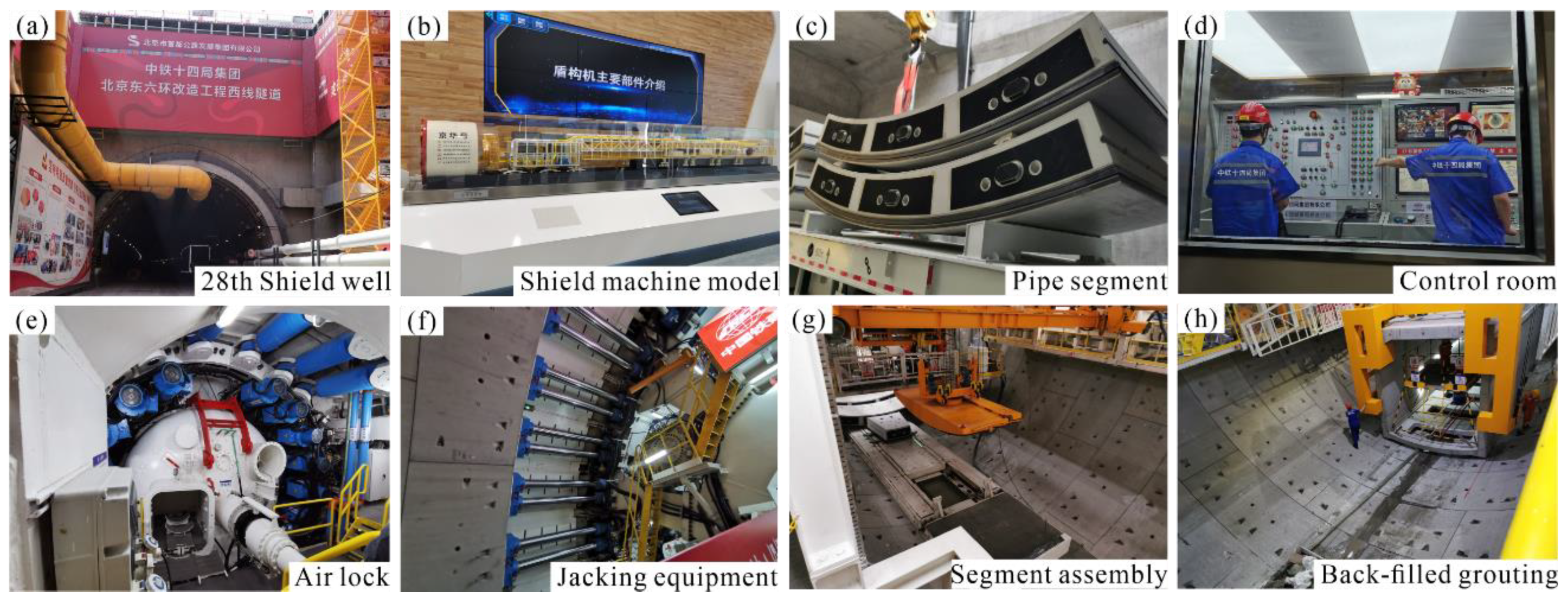
The tunnel segment in question exhibits a maximum excavational radius of 15.48 m, with an outer diameter of 15.4 m and an inner diameter of 14.75 m. For a more comprehensive illustration of the shield tunnel and the shield machine, please refer to Figure 2.
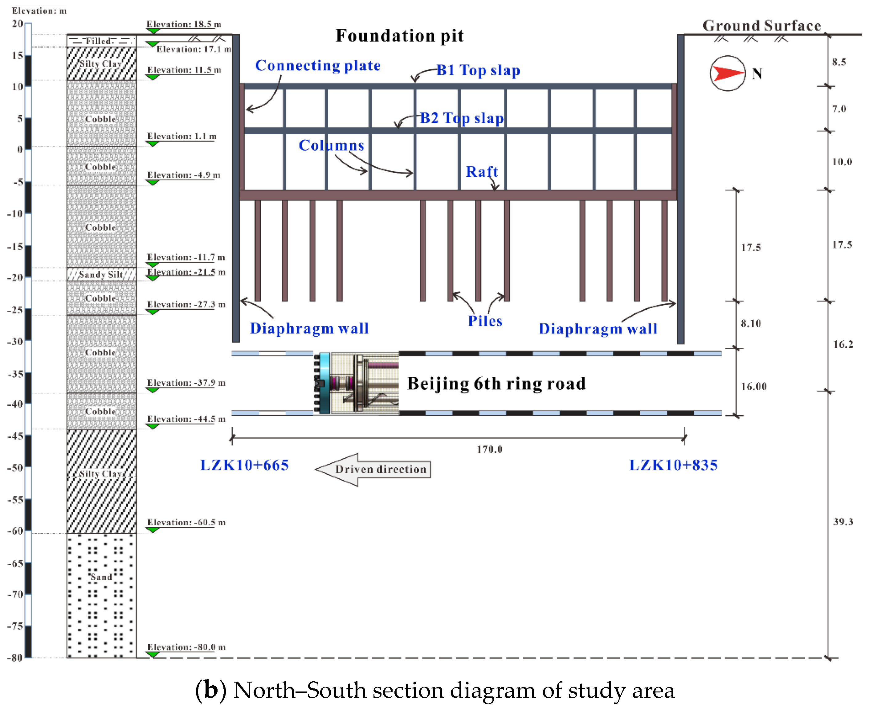
Within the designated study area, the shield tunnel reaches a maximum depth of approximately 59 m, while its minimum depth is 23 m as it crosses the foundation pit. The underground structure situated beneath this pit, which the tunnel traverses, consists of an underground station supported by a raft pile foundation. The foundation pit itself spans 170 m by 54.5 m and attains a depth of 29.9 m. It is noteworthy that the Beijing sub-center station has been erected within this foundation pit. For a visual representation of the spatial relationship between the station and the shield tunnel, please refer to Figure 3.
The soils present at the project site can be classified into three main categories, namely, the artificial accumulation layer, Neogene sedimentary layer, and Quaternary sedimentary layer. The site is characterized by the co-deposition of clay, silt, and sand. The lithology of the soil and its mechanical properties were determined based on the outcomes of field investigations, in situ testing, and indoor soil testing. The corresponding results are summarized in Table 1.
The various parameters of the soil were provided by a third-party exploration unit, taking into account the influence of various factors on the physical parameters of the soil. The exploration report included the effects of soil saturation on the physical parameters of the soil [26,27].

2.2. Establishment of Numerical Model

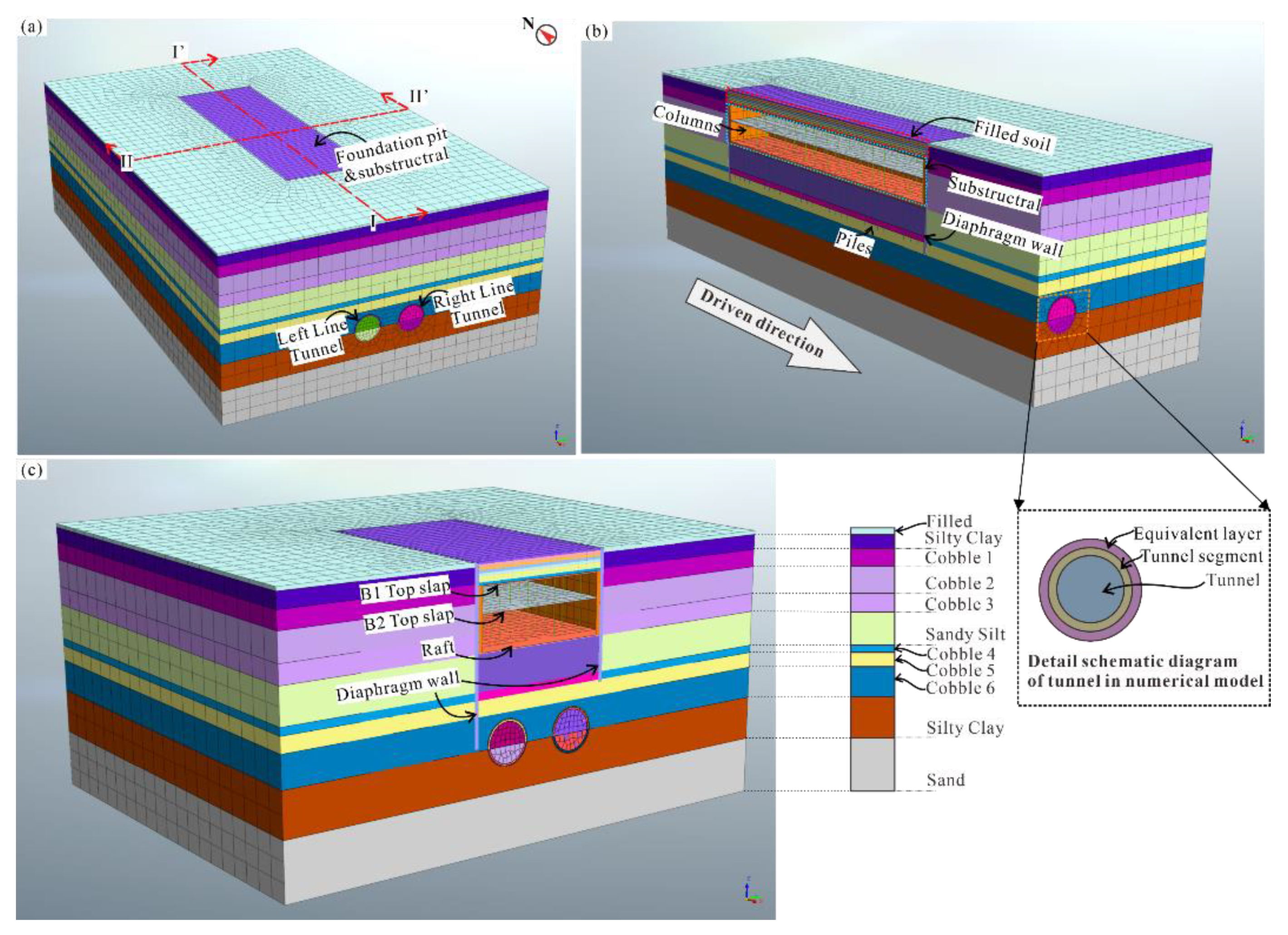
Based on the design scheme and geological conditions, a three-dimensional finite element method model (hereafter referred to as the FEM model) was developed using Midas GTS NX software to simulate the study area in this project. The dimensions of the FEM model were 320 m by 170 m in length and width, respectively, with a height of 100 m. A hexahedral mesh was implemented for meshing the model. Normal constraints were applied to all boundary surfaces except for the upper boundary surface of the model. Figure 4 depicts the resulting FEM model.
The Mohr–Coulomb model was utilized as the soil constitutive model, while an elastic constitutive model was employed for the reinforced concrete structure. It is worth mentioning that when the Mohr–Coulomb criterion and the linear elastic model are combined within the same numerical model, there is a certain degree of error introduced due to the implicit assumption that the soil exhibits elastic deformation characteristics before failure [28,29]. However, in this model, considering that the parameters of the Mohr–Coulomb criterion could be directly obtained from the geological survey report of a professional surveying agency without the need for further estimation of other parameters required by alternative constitutive models (which were not provided in the geological survey report), the Mohr–Coulomb criterion were chosen to avoid errors resulting from the selection of parameters. Furthermore, regarding the aforementioned error caused by the implicit assumption, as the total deformation in this case is not significant, the error remains within an acceptable range.
To simplify the model, the reinforcement within the concrete was not accounted for, and the elastic modulus of the reinforced concrete structure was substituted with an equivalent value. Moreover, to consider the impact of segment joints on the overall strength, the concrete strength of the shield segment was reduced to 85% of its original strength. The soil layer parameters are presented in Table 1, while the parameters of other components are displayed in Table 2.
During the actual working conditions, the excavation of the left line tunnel was carried out initially. Subsequently, the right line tunnel was excavated after the shield machine had completely passed through the bottom of the foundation pit. Prior to the tunnel construction, a 2 m thick layer of lightweight concrete was backfilled to the top of the underground structure to prevent it from floating due to the impact of the tunnel construction. To control the surface subsidence while the shield machine was crossing the foundation pit, both synchronous grouting and backwall grouting were employed.
In the numerical model employed in this research, the equivalent layer method was utilized to simulate the soil disturbance and loss caused by the shield machine. Based on the construction data, the shield tail gap was determined to be 8 cm. Consequently, the equivalent layer thickness was set to 30 cm, considering the cumulative effects of various factors.
To investigate the impact of different construction methods on the deformation of the foundation pit bottom surface, the working conditions presented in Table 3 were established while ensuring the accuracy of the model.
To elaborate on the implementation of the various construction methods specified in Table 3 within the model, the following brief introductions are provided:
(1) Synchronous grouting: In this method, the properties of the equivalent layer in the numerical model are modified to match those of the synchronous grout slurry, as indicated in Table 2. Synchronous grouting is carried out when the segment exits the tail of the shield machine.
(2) Backwall grouting: This method involves modifying the properties of the equivalent layer in the numerical model to reflect those of the back wall grouting layer, as specified in Table 2. Backwall grouting is conducted after the tunnel segment has separated from the third ring segments at the tail of the shield machine.
(3) Backfill thickness: The thickness of backfill at the top of the underground structure is altered in the numerical model for this method. The backfilling material used is lightweight concrete, and its properties are provided in Table 2.
After enumerating four construction methods that could exert a potential impact on ground subsidence at the base of a foundation pit, a simulation was conducted comprising eight cases (Table 3). Case 1 was designed to replicate a practical scenario, and was employed for the purpose of model validation. Cases 2 through 4 were utilized to examine the influence of two distinct types of grouting techniques on surface subsidence at the base of the foundation pit. Similarly, Cases 5 and 6 were employed to study the impact of backfill thickness on surface subsidence at the base of the foundation pit, while Cases 7 and 8 were used to investigate the effect of the distance between two shield machines on surface subsidence at the base of the foundation pit.

3. Results

3.1. Model Validation

In this case study, the main causes of deformation of the underground structure and soil are attributed to two aspects: unloading rebound caused by excavation of the foundation pit during the construction of the underground structure, and soil loss caused by the passage of an ultra-large diameter shield tunnel through the underground structure, resulting in soil deformation. Both types of soil deformation ultimately manifest as vertical deformation of the structure’s base plate. We believe that if the numerical model can reflect the trend of base plate deformation caused by the combined effect of the above two factors, then the accuracy of the numerical model can be considered adequate. Therefore, this paper selected 14 on-site monitoring points on the raft foundation of the underground structure and validated the correctness of the numerical model by comparing the vertical deformation data at the same positions.
The monitoring points and their value comparison are shown in Figure 5.
According to Figure 5, the law of raft deformation in the numerical model is basically consistent with the on-site monitoring data. Therefore, it can be considered that the numerical model is reliable. In recent years, ground subsidence induced by shield tunnelling has been adequately researched. However, the ground subsidence at the bottom of pits with raft-pile foundations induced by shield tunnelling lacks research attention. Therefore, based on the validity of this numerical model, influences on ground subsidence at the bottom of this foundation pit from the rest of eight cases are discussed. Cross-section AA’ in Figure 5b is selected as a typical section for analysis in the next subsection.

3.2. Different Grouting Schemes

Cases 1–4 considered the influences on ground subsidence at the bottom of the foundation pit induced by different grouting schemes used in shield tunnel construction, as shown in Table 3. The results are plotted in Figure 6.
Figure 6a shows the subsidence after left tunnel excavation. As shown in Figure 6a, when the left tunnel was excavated the ground subsidence curve was approximately fitted to the Gaussian curve. However, the peak settlement of the curve shifted to the right in the horizontal direction to a certain extent. Comparing different grouting schemes, no grouting had the maximum ground subsidence, while the practical case (with both backwall grouting and synchronous grouting) had the minimum ground subsidence. The effect on controlling ground subsidence of synchronous grouting was better than backwall grouting, which is because synchronous grouting is timelier for soil support.
After the twin tunnel excavation, the whole ground subsidence increased noticeably. Moreover, it was more noticeable for the peak settlement of the curve that shifted to the right in the horizontal direction. The shift of the curve was most likely conducted by the different lengths of the diaphragm walls at each side of the twin tunnel. In the horizontal direction, with the excavation of the twin tunnel the soil under the foundation pit experienced unloading at the horizontal direction. Due to the different lengths of the diaphragm walls, on the whole the soil moved towards the right side. In terms of the vertical direction, the subsidence at the bottom of foundation pit was mainly concentrated above the post-excavation tunnels. In addition, it is worth pointing out that in the backwall grouting case the curve is flatter than that in synchronous grouting case. This is most likely because that backwall grouting case has a higher Young’s modulus, which provides more horizontal resistance force in the horizontal direction. Therefore, combining the two grouting methods can obtain more ideal results for controlling the pit bottom ground subsidence.

3.3. Different Backfill Thickness

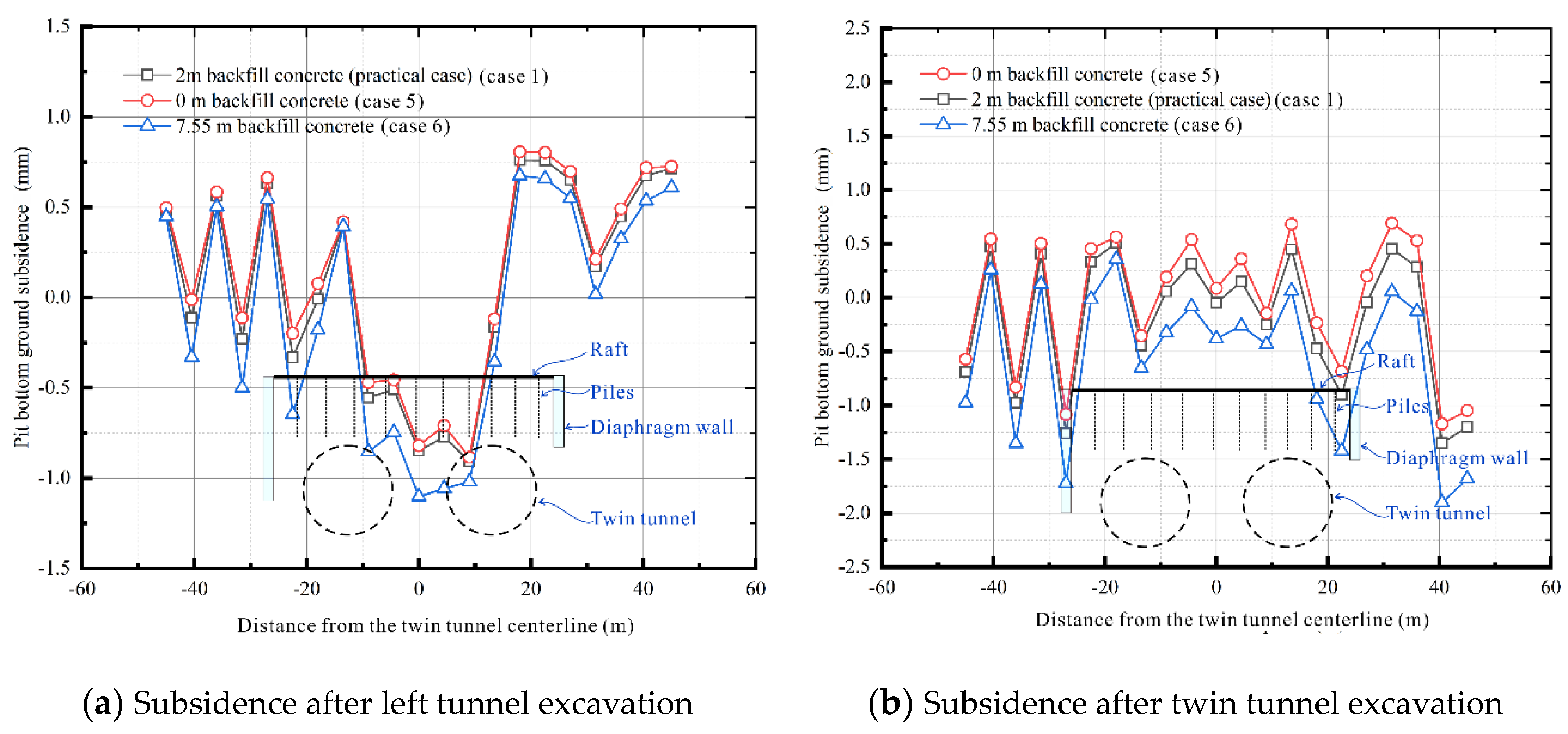
Cases 1, 5, and 6 considered influences on ground subsidence at the bottom of the foundation pit with different backfill thicknesses at the top of the underground structure. The results are plotted in Figure 7.
As is shown in Figure 7, the thicker the backfill thickness before tunnel excavation, the greater the settlement of the foundation pit bottom after tunnel excavation. In Figure 7a, it can be seen that the ground surface at the bottom of the foundation pit directly above the tunnel has basically subsided. However, when the twin tunnel has been excavated, the ground surface at the bottom of the foundation pit directly above the tunnel has basically moved upward. This phenomenon is likely due to the excavation of a large diameter tunnel which produced a large unloading, meaning that the soil moved upward instead of subsiding.
Different backfill thicknesses have different effects on the settlement control of foundation pit bottom. This is related to the thickness of backfill as well as to the tunnel diameter, because a large amount of unloading in super-large diameter tunnels may cause the soil to move upward.

3.4. Different Distance between Shield Machines

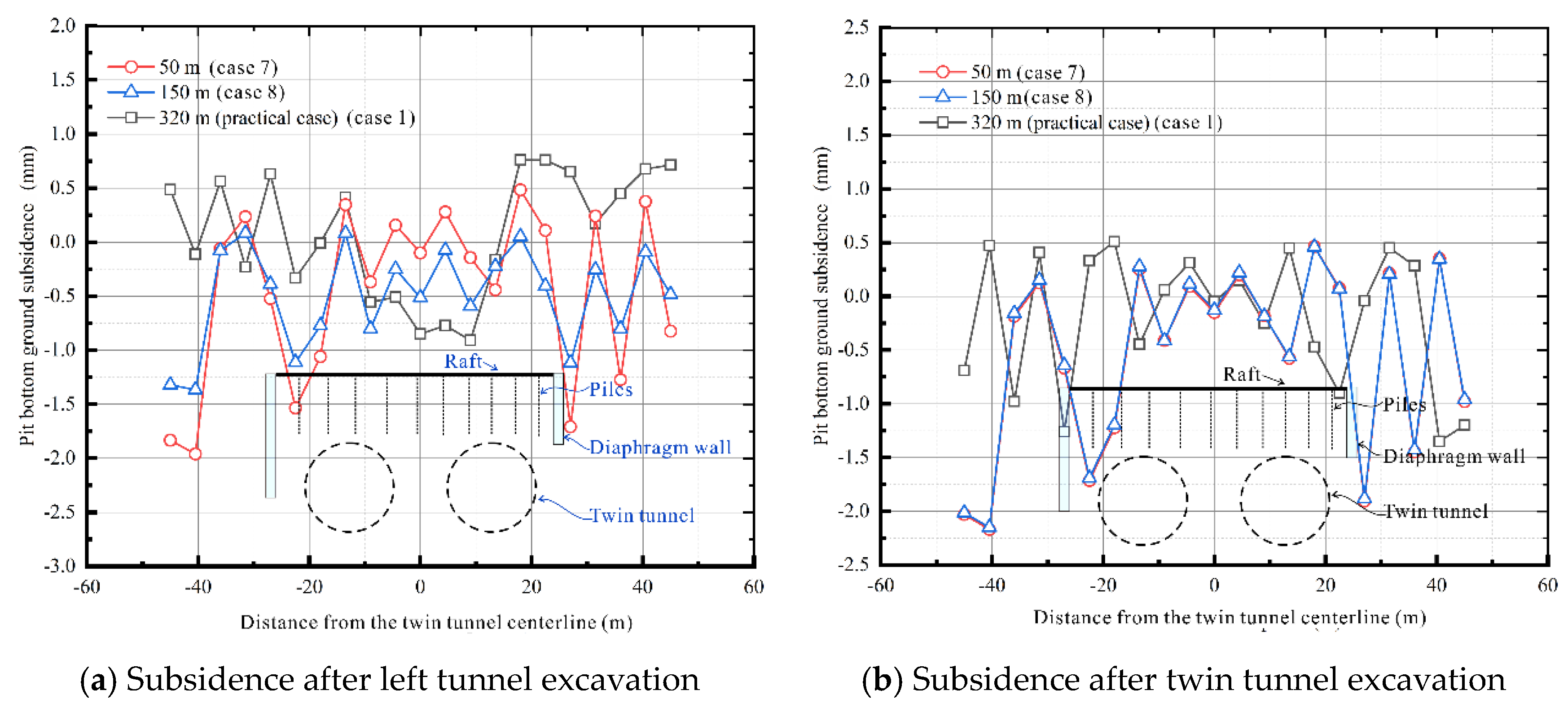
Cases 1, 7, and 8 considered influences on ground subsidence at the bottom of the foundation pit with different distances between shield machines. The results are plotted in Figure 8.
In general, as shown Figure 8a, the closer the two shield machines are, the greater the settlement of the foundation pit bottom. In Figure 8b, different distances between shield machines have no significant impact on the final settlement. It can be concluded that, during tunnel construction, the closer the two shield machines are, the greater the settlement at the bottom of the foundation pit will be, while the difference in the final total subsidence is small.

4. Discussion

4.1. Influence of Load Characteristics on Settlement Curve

In Section 3, results of the eight cases have been plotted and thoroughly discussed. Combining the characteristics of this practical engineering and super-large diameter shield tunnels, there are a number of issues worth discussing. In this research, the influence of a super-large diameter shield tunnel under-crossing the foundation pit on the settlement curve of the soil at the bottom of the foundation pit was studied. Therefore, the unique load characteristics of the project have a great impact on the settlement curve, mainly in the following three aspects.
(1) When the shield tunnel under-crosses the foundation pit, the asymmetry of the supporting structures on both sides of the foundation pit lead to deviation of the settlement curve.
The supporting structure of the foundation pit in this practical engineering is the diaphragm wall, which is a cantilevered retaining structure. According to Gong [30], the actual earth pressure distribution of the soil under foundation pit can be seen in Figure 9.
When a cantilevered retaining structure exists, the peak value of the passive earth pressure of the soil under the foundation pit is located near the ground surface of the pit bottom. Therefore, when the twin tunnel is excavated, the asymmetry of the supporting structures on both sides of the foundation pit can lead to non-negligible horizontal displacement of the ground surface at the bottom of foundation pit. This explains the reason for the deviation of the settlement curve in Section 3 from the perspective of soil mechanics.
(2) When the grouting effect is ideal, because the soil loss is small, the super-large diameter shield tunnel may cause upward displacement of the soil due to unloading.
In practical engineering, ground subsidence is always induced by soil losses. The soil losses are induced by the gap in the tail of shield machines. From the perspective of soil mechanics, tunnel excavation causes soil unloading. When the rebound effect caused by soil unloading is less than the total weight of the segments, the deformation law of the soil above the tunnel results in settlement. Therefore, when the tunnel diameter is small, this unloading rebound effect is often ignored by researchers. However, in terms of the super-large diameter shield tunnel in this project, this unloading rebound effect cannot be ignored. When the tunnel grouting support effect is good, the soil mass floating caused by this unloading rebound will be more obvious.
(3) When the shield tunnel under-crosses the foundation pit, the piles in the raft-piles foundation can strengthen the soil and reduce the actual loss rate of the soil.
In this project, the piles in the pile raft foundation are friction piles. Therefore, there is a strong interaction between the pile and the soil. When the tunnel under-crosses the pile, the friction between the pile and the soil can strengthen the soil, which can reduce the actual settlement of the soil on the surface of the bottom of the foundation pit. According to Peck (1969), the actual ground settlement caused by the excavation of a single shield tunnel under the non-grouting situation in this project can be expressed as in Equations (1)–(3).
S x = S m a x · exp { x 2 2 i 2 }
i = Z 2 π tan 45 ° φ 2
S m a x = V s i · 2 π
In Equations (1)–(3), V s is the soil volume loss during the excavation of the shield tunnel, i   is the distance between the tunnel center line and the bending point of the settlement curve, φ is the internal friction angle of the stratum where the tunnel is located, and Z is the distance from the surface to the center of the tunnel.
In order to fit the stratigraphic conditions in Beijing, Equations (1)–(3) were modified according to the correction coefficient proposed by Yao [31] et al., who considered that the maximum surface subsidence ( S m a x ,   Equation   3 ) correction coefficient α should be 0.6–0.9 in the stratum present in Beijing and that Equation (2) should be corrected by β , the value of which was supposed to be 0.5 to 0.9. Therefore, the subsidence curve in the Beijing area should be expressed as in Equation (4).
S x = α · S m a x · exp { x 2 2 β · i 2 }
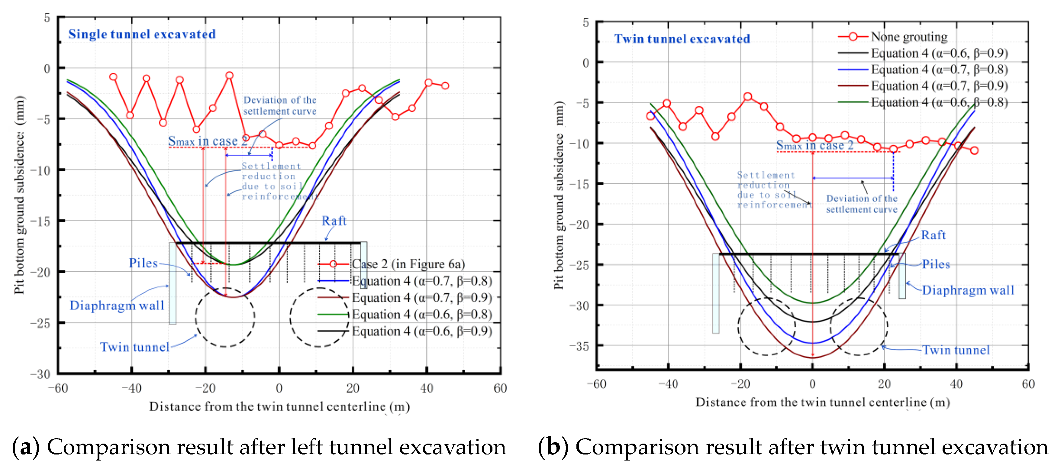
Taking the bottom plane of the foundation pit as the surface, the surface settlement curve is drawn according to Equation (4), as shown in Figure 10a. Similarly, the settlement curve is drawn by the prediction formula of the double track parallel tunnel proposed by Wei et al. [32], shown in Figure 10b. Combined with the correction coefficient, the prediction formula of the double track parallel tunnel proposed by Wei et al. [32] can be expressed as in Equation (5).
S x = α l · S m a x · exp x + 0.5 L 2 2 β l · i 2 + α r · S m a x · exp x 0.5 L 2 2 β r · i 2
In Equation (5), α l   ( α r ) is the correction coefficient for S m a x of the left (right) tunnel and L is the distance between the center points of the twin tunnel.
The strengthening effect on soil from the piles and the deviation of the settlement curve caused by asymmetric horizontal loading is clearly expressed in Figure 10. In order to better determine the magnitude of these two impacts, the curve of Case 2 was analyzed. The approximate expression is shown in Equations (6) and (7).
S x = γ α · S m a x · exp { x ± μ B 2 2 β · i 2 }
S x = γ l α l · S m a x · exp x + 0.5 L ± μ l B 2 2 β l · i 2 + γ r α r · S m a x · exp x 0.5 μ r L ± μ l B 2 2 β r · i 2
In Equations (6) and (7), γ is the correction coefficient considering the strengthening effect on soil induced by piles, μ is the correction coefficient considering the deviation of the settlement curve caused by asymmetric horizontal loading, and B is the width of the foundation pit. The positive and negative values are related to the unloading direction of the horizontal load.
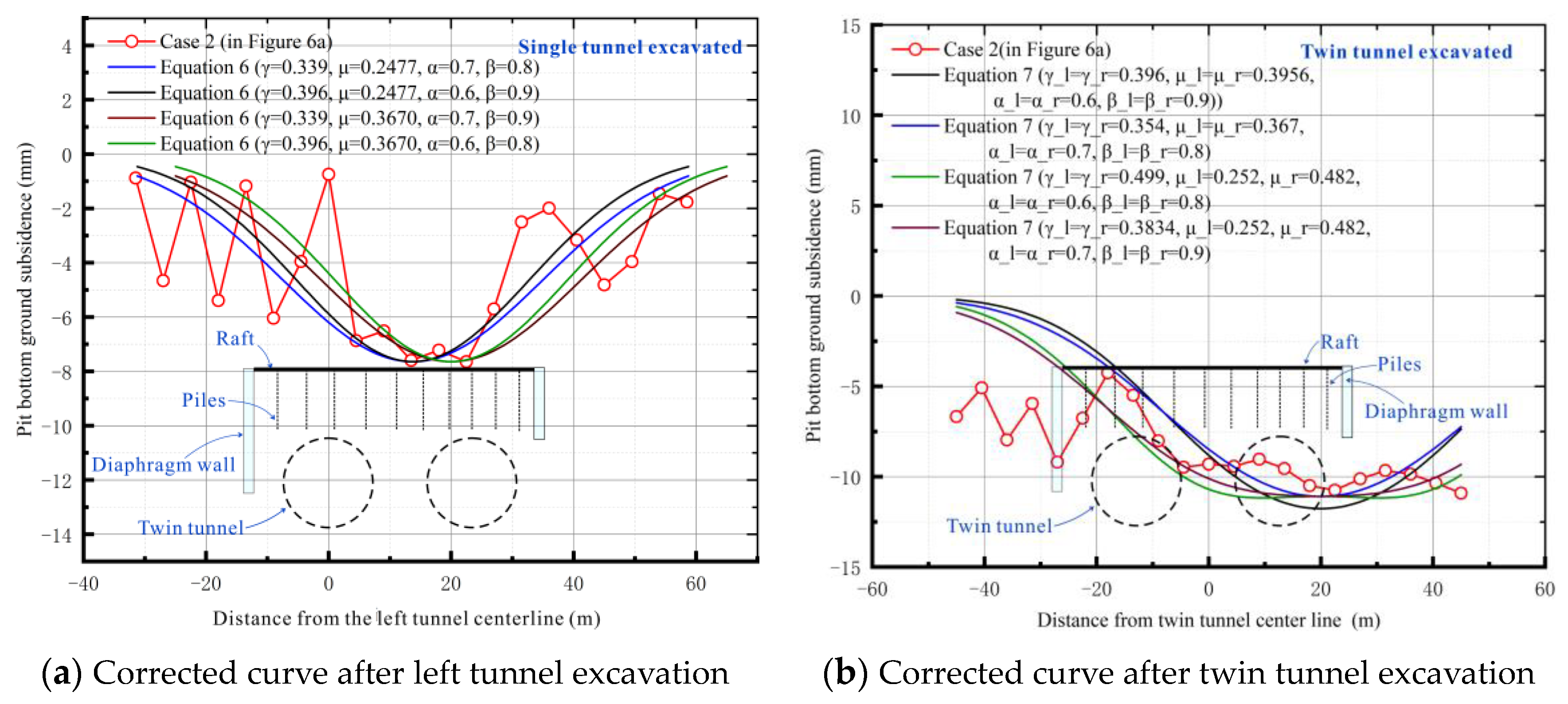
In this research, the values of μ and γ can be obtained according to the curve data in Figure 10. The corrected settlement curve is shown in Figure 11.
It can be seen from Figure 11 that the correction factors γ and μ well reflect the changes in the settlement curve under the influence of the load characteristics of the practical project. When the shield tunnel passes through the foundation pit with pile raft foundation, the reinforcement effect of the piles on the soil can be considered through the correction factors γ . When there is asymmetric horizontal loading of the soil under the foundation pit, the settlement curve can be corrected by the correction factor μ .

4.2. Limitations and Prospects

In the previous subsection, the Gaussian settlement curve was modified by considering the load characteristics of a super-large shield tunnel under-crossing the foundation pit. Although the proposed two modified parameters can well reflect the settlement of the soil in this project, there are several aspects worth improving.
First, practically speaking, the correction factors γ not only reflect the strengthening effect from the piles, they include the unloading effect due to the excavation of the shield tunnel. Therefore, when calculating the value of γ , it is more accurate to take the unloading effect into account.
Second, there is no accurate formula for calculating these two parameters. In this research, the two factors were obtained by inverse analysis. If a more accurate correction factor needed to be obtained, a lot of data from similar practical projects would need to be collected. However, at present, super-large diameter shield tunnels are rare, especially those under-crossing a foundation pit. Therefore, Therefore, it is a long-term process to improve the correction parameters.
In terms of the prospects of this research, the main application is to quickly determine the soil displacement field of pile-raft foundations under the influence of tunnel excavation. The determination of the displacement field can further identify potential negative skin friction areas on the piles, providing a possible quick calculation method for the calculation of the tunnel excavation’s impact on the lateral skin friction of the piles. In the case of this study, it is possible to judge whether soil displacement can reflect the potential skin friction effect by comparing the soil displacement data with the variation of the axial force in the pile body. However, for further theoretical calculations, more detailed experiments are required for validation. This article does not discuss this aspect.
As for the potential long-term effects of the excavation on the surrounding soil and structures, the impact of tunnel excavation on the surrounding soil and adjacent building structures can come from many aspects.
For example, in practical engineering, the settlement of the soil at the bottom of the raft caused by soil loss from tunnel excavation may not fully manifest in the short term, which is closely related to the amount of grouting used in the actual construction process and the grouting material adopted. If the grouting amount is insufficient, the upper soil of the tunnel may further settle in the future, resulting in settlement of the raft; on the other hand, if the grouting amount is appropriate, no further deformation may occur. As for the potential rapid calculation of the pile-side friction, according to the law of pile-side friction, the generation of negative frictional resistance is closely related to the relative displacement between the pile and soil. Therefore, it is necessary to quickly determine the distribution and variation of negative frictional resistance on the pile side under the influence of shield tunneling and quickly determine the displacement field of the pile-side soil. At the same time, by comparing the displacement of the pile-side soil at the corresponding position with the compression of the pile body, the distribution of the negative frictional resistance can be quickly determined. For the compression of the pile body, it can currently be assumed to be uniformly compressed under concentrated force.
In addition, according to the solution provided by Mindlin, the calculation of additional stress at any position below the ground surface can be obtained through σ z = P h 2 I p , where I p is an integral coefficient considering the influence of the pile.
Based on the settlement value, the force distribution of the pile-side soil at each position can be deduced using the layer summation method and different integral coefficients. The distribution of this force is opposite in direction and equal in magnitude to the pile-side frictional resistance.
Because the derivation process is more complicated, this paper does not describe it here.
Overall, for the case of deep foundation pit engineering with pile-raft foundations crossed by ultra-large diameter shield tunnels discussed in this article, the accurate settlement law of the soil at the bottom of the foundation pit can provide a possible way for rapid prediction of the negative skin friction variation of piles. In practical engineering, after the completion of underground structures it is often difficult to measure the impact of tunnel excavation on the foundation piles by re-installing sensors. However, this soil settlement prediction method provides a possible means of rapid calculation of the negative skin friction distribution, which enables engineers to take targeted protective measures for areas that may be heavily affected by tunnel excavation.

5. Conclusions

In this research, a super-large diameter shield twin tunnel was reported. The shield twin tunnel under-crossed a deep foundation pit which contained an underground structural with a raft-pile foundation.
Influences on the ground subsidence curve from different construction methods were studied in this paper. Eight numerical models were established to explore these influences. One of these models was consistent with the practical project, aiming to validate the correctness of these numerical models. Through these eight numerical models, we drew the following conclusions:
(1) For the super-large diameter shield tunnel, the effect on controlling ground subsidence of synchronous grouting was better than backwall grouting, because synchronous grouting is timelier for soil support. Backwall grouting can grant the soil a higher Young’s modulus, which can provide more horizontal resistance force in the horizontal direction. Therefore, combining the two grouting methods can obtain more ideal results on controlling pit-bottom ground subsidence.
(2) The excavation of super-large diameter shield tunnels may cause uplift of the surface soil, and proper backfilling can control the uplift value.
First, when an extra-large diameter shield tunnel passes beneath a foundation pit or a lightweight underground structure, if the weight of the underground structure is insufficient to counterbalance the unloading effects caused by the excavation of the foundation pit and the tunnel this may result in upward movement of the surface soil at the bottom of the foundation pit.
Second, in the construction of an extra-large diameter shield tunnel the construction parties often tend to be conservative, and an excessive amount of grouting can cause soil expansion and subsequent uplift of the superficial soil.
Third, due to the continuous increase in the groundwater level in Beijing, after the completion of the engineering project a persistent rise in the water level may lead to the uplift of the tunnel, thereby introducing uplift of the superficial soil. This aspect requires close attention.
(3) During tunnel construction, the closer the two shield machines are, the greater the settlement at the bottom of the foundation pit will be; however, the difference in the final total subsidence is small.
In addition, when combining our eight models we found that the studied project has very unique load characteristics. These load characteristics have a greater impact on the shape of the surface settlement curve. To solve this problem, two correction coefficients were proposed to correct the surface settlement curve. Following the inverse analysis method, the modified settlement curves of single- and double-track tunnel excavation were obtained. These two formulas can well reflect the settlement law of the soil at the foundation pit bottom under-crossed by the super-large diameter shield tunnel.
Furthermore, this soil settlement prediction provides a possible way for rapid calculation of the negative skin friction distribution, which enables engineers to take targeted protective measures for areas that may be heavily affected by tunnel excavation.

Author Contributions

Validation, Y.L. and H.L.; Investigation, Y.J., X.G. and H.L.; Resources, Y.J.; Data curation, Y.L. and X.G.; Writing—original draft, Y.J. and Y.L.; Writing—review & editing, Y.L. and A.Y.; Funding acquisition, A.Y. All authors have read and agreed to the published version of the manuscript.

Funding

This research was funded by [National Natural Science Foundation of China] grant number [51578023] and the APC was funded by [Aijun Yao].

Institutional Review Board Statement

Not applicable.

Informed Consent Statement

Not applicable.

Data Availability Statement

The data used to support the findings of this study are available from the corresponding author upon reasonable request.

Conflicts of Interest

The authors declare that there are no conflict of interest regarding the publication of this paper.

References

  1. Kouroussis, G.; Vogiatzis, K.; Kassomenos, P. Special issue on impact on the urban environment and the quality of life from the construction and operation of lrt (light rapid transit) systems preface. Sci. Total Environ. 2016, 568, 1275. [Google Scholar] [CrossRef]
  2. Cui, X.; Ye, M.; Yan, Z. Performance of a foundation pit supported by bored piles and steel struts: A case study. Soils Found. 2018, 58, 1016–1027. [Google Scholar] [CrossRef]
  3. Wang, J. Super-large diameter shield tunneling technologies in China in recent decade. Tunn. Constr. 2017, 37, 330. Available online: https://kns.cnki.net/kcms/detail/detail.aspx?FileName=JSSD201703014&DbName=CJFQ2017 (accessed on 30 March 2017). (In Chinese).
  4. Chakeri, H.; Ozcelik, Y.; Unver, B. Effects of important factors on surface settlement prediction for metro tunnel excavated by EPB. Tunn. Undergr. Space Technol. 2013, 36, 14–23. [Google Scholar] [CrossRef]
  5. Zhu, C. Control of surface settlement by considering shield tunneling technology. KSCE J. Civ. Eng. 2017, 21, 2896–2907. [Google Scholar] [CrossRef]
  6. Lai, J.; Zhou, H.; Wang, K.e.; Qiu, J.; Wang, L.; Wang, J.; Feng, Z. Shield-driven induced ground surface and Ming Dynasty city wall settlement of Xi’an metro. Tunn. Undergr. Space Technol. 2020, 97, 103220. [Google Scholar] [CrossRef]
  7. Lin, X.T.; Chen, R.P.; Wu, H.N.; Cheng, H.Z. Deformation behaviors of existing tunnels caused by shield tunneling undercrossing with oblique angle. Tunn. Undergr. Space Technol. 2019, 89, 78–90. [Google Scholar] [CrossRef]
  8. Ou, C.Y.; Hsieh, P.G.; Chiou, D.C. Characteristics of ground surface settlement during excavation. Can. Geotech. J. 1993, 30, 758–767. [Google Scholar] [CrossRef]
  9. Song, Z.; Tian, X.; Zhang, Y. A New Modified Peck Formula for Predicting the Surface Settlement Based on Stochastic Medium Theory. Adv. Civ. Eng. 2019, 2019, 7328190. [Google Scholar] [CrossRef]
  10. Fang, Y.S.; Lin, J.S.; Su, C.S. An estimation of ground settlement due to shield tunnelling by the Peck–Fujita method. Can. Geotech. J. 1994, 31, 431–443. [Google Scholar] [CrossRef]
  11. Suwansawat, S.; Einstein, H.H. Artificial neural networks for predicting the maximum surface settlement caused by EPB shield tunneling. Tunn. Undergr. Space Technol. Inc. Trenchless Technol. Res. 2006, 21, 133–150. [Google Scholar] [CrossRef]
  12. Jallow, A.; Ou, C.Y.; Lim, A. Three-dimensional numerical study of long-term settlement induced in shield tunneling. Tunn. Undergr. Space Technol. 2019, 88, 221–236. [Google Scholar] [CrossRef]
  13. Jin, D.; Shen, X.; Yuan, D. Theoretical analysis of three-dimensional ground displacements induced by shield tunneling. Appl. Math. Model. 2019, 79, 85–105. [Google Scholar] [CrossRef]
  14. Fang, K.; Yang, Z.; Jiang, Y.; Sun, Z.; Wang, Z. Surface subsidence characteristics of fully overlapping tunnels constructed using tunnel boring machine in a clay stratum. Comput. Geotech. 2020, 125, 103679. [Google Scholar] [CrossRef]
  15. Zhang, N.; Zhou, A.; Pan, Y.; Shen, S.-L. Measurement and prediction of tunnelling-induced ground settlement in karst region by using expanding deep learning method. Measurement 2021, 183, 109700. [Google Scholar] [CrossRef]
  16. Zhang, K.; Lyu, H.-M.; Shen, S.-L.; Zhou, A.; Yin, Z.-Y. Evolutionary hybrid neural network approach to predict shield tunneling-induced ground settlements. Tunn. Undergr. Space Technol. 2020, 106, 103594. [Google Scholar] [CrossRef]
  17. Shi, J.; Fu, Z.; Guo, W. Investigation of geometric effects on three-dimensional tunnel deformation mechanisms due to basement excavation. Comput. Geotech. 2019, 106, 108–116. [Google Scholar] [CrossRef]
  18. Liu, B.; Zhang, D.W.; Yang, C.; Zhang, Q.B. Long-term performance of metro tunnels induced by adjacent large deep excavation and protective measures in Nanjing silty clay. Tunn. Undergr. Space Technol. 2020, 95, 103147. [Google Scholar] [CrossRef]
  19. Ng, C.W.W.; Shi, J.; Mašín, D.; Sun, H.; Lei, G.H. Influence of sand density and retaining wall stiffness on three-dimensional responses of tunnel to basement excavation. Can. Geotech. J. 2015, 52, 1811–1829. [Google Scholar] [CrossRef]
  20. Zhang, X.; Wei, G.; Jiang, C. The study for longitudinal deformation of adjacent shield tunnel due to foundation pit excavation with consideration of the retaining structure deformation. Symmetry 2020, 12, 2103. [Google Scholar] [CrossRef]
  21. Shi, J.; Zhang, X.; Chen, Y.; Chen, L. Numerical parametric study of countermeasures to alleviate basement excavation effects on an existing tunnel. Tunn. Undergr. Space Technol. 2018, 72, 145–153. [Google Scholar] [CrossRef]
  22. Li, M.G.; Chen, J.J.; Wang, J.H.; Zhu, Y.F. Comparative study of construction methods for deep excavations above shield tunnels. Tunn. Undergr. Space Technol. 2018, 71, 329–339. [Google Scholar] [CrossRef]
  23. Zhang, X.; Wei, G.; Lin, X.; Xia, C.; Wei, X. Transverse Force Analysis of Adjacent Shield Tunnel Caused by Foundation Pit Excavation Considering Deformation of Retaining Structures. Symmetry 2021, 13, 1478. [Google Scholar] [CrossRef]
  24. Wei, G.; Hu, L.W.; Chen, K.L. Numerical Simulation of Effect of Foundation Pit Excavation on Underlain Shield Tunnel. Appl. Mech. Mater. 2014, 580–583, 1001–1007. [Google Scholar] [CrossRef]
  25. Qiu, J.; Jiang, J.; Zhou, X.; Zhang, Y.; Pan, Y. Analytical solution for evaluating deformation response of existing metro tunnel due to excavation of adjacent foundation pit. J. Cent. South Univ. 2021, 28, 1888–1900. [Google Scholar] [CrossRef]
  26. Lu, N.; Kaya, M. Power Law for Elastic Moduli of Unsaturated Soil. J. Geotech. Geoenviron. Eng. 2014, 140, 46–56. [Google Scholar] [CrossRef]
  27. Oliver-Denzil, S.; Taylor, M.A.; Farshid, V. Statistical distributions of wave velocities and elastic moduli in near-surface unsaturated soils. Soil Dyn. Earthq. Eng. 2022, 157, 107247. [Google Scholar] [CrossRef]
  28. Ghorbani, J.; Airey, D.W. Modelling stress-induced anisotropy in multi-phase granular soils. Comput. Mech. 2021, 67, 497–521. [Google Scholar] [CrossRef]
  29. Fang, Y.; Jian, C.; Dariusz, W.; Nikolaos, N.; Ran, Y.; Yi, H. Subsurface Settlements of Shield Tunneling Predicted by 2D and 3D Constitutive Models considering Non-coaxiality and Soil Anisotropy: A Case Study. Can. Geotech. J. 2022, 59, 424–440. [Google Scholar] [CrossRef]
  30. Gong, X.N. Design Manual for Deep Foundation Pit Construction; China Building Industry Press: Beijing, China, 2017; 134p, ISBN 978-7-112-20808-1. (In Chinese) [Google Scholar]
  31. Yao, A.; Zhao, Q.; Guan, J.; Liu, F.; Su, N. Improvement of Peck formula based on Beijing underground subway tunnel construction. Chin. J. Undergr. Space Eng. 2010, 6, 789–793. Available online: https://kns.cnki.net/kcms/detail/detail.aspx?FileName=BASE201004024&DbName=CJFQ2010 (accessed on 5 May 2023). (In Chinese).
  32. Wei, G. Prediction of soil settlement caused by double-line parallel shield tunnel construction. Disaster Adv. 2013, 6, 23–27. [Google Scholar]
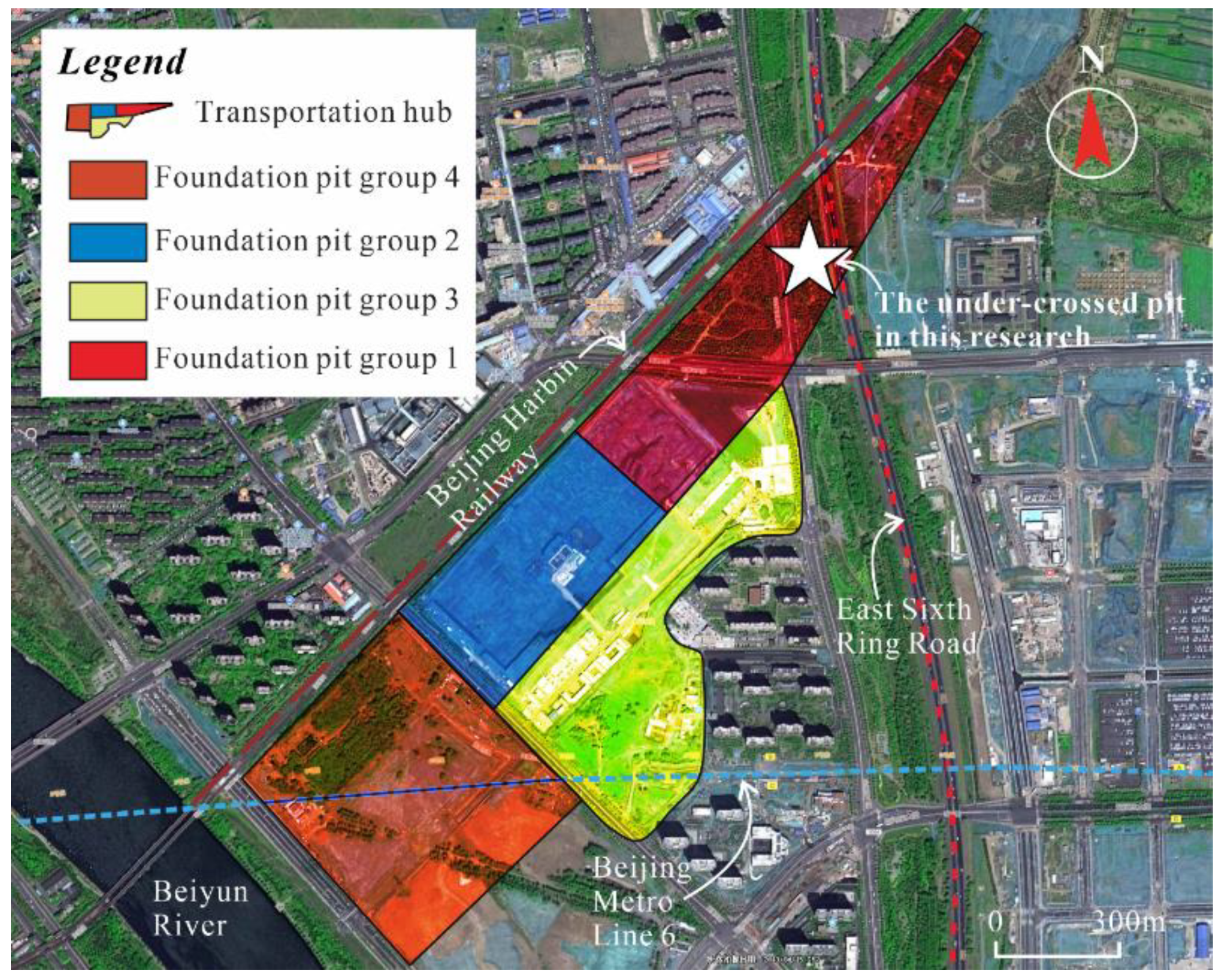
Figure 1. Planner view of Beijing sub-center station.
Applsci 13 05774 g001
Figure 2. Detailed diagram in shield tunnel and machine. (a) The 28th Shield well of this engineering case; (b) Shield machine model; (c) Pipe segments; (d) Control room; (e) Air lock; (f) Jacking equipment; (g) Segment assembly; (h) Back-filled grouting.
Applsci 13 05774 g002
Figure 3. Location relationship between the station and the shield tunnel.
Applsci 13 05774 g003aApplsci 13 05774 g003b
Figure 4. The finite element model: (a) overall schematic diagram of the model; (b) I-I’ section diagram of the model; (c) II-II’ section diagram of the model.
Applsci 13 05774 g004
Figure 5. Monitoring points and their value comparison. (a) Internal perspective view of the numerical model; (b) Comparison of numerical model and site monitoring points.
Applsci 13 05774 g005
Figure 6. Pit bottom subsidence induced by different grouting methods.
Applsci 13 05774 g006
Figure 7. Pit bottom subsidence with different backfill thicknesses.
Applsci 13 05774 g007
Figure 8. Pit bottom subsidence with different distances between shield machines.
Applsci 13 05774 g008
Figure 9. Actual earth pressure distribution of the soil under the foundation pit.
Applsci 13 05774 g009
Figure 10. Comparison between empirical formula and numerical model.
Applsci 13 05774 g010
Figure 11. Corrected curve of ground subsidence at the bottom of the pit.
Applsci 13 05774 g011
Table 1. Mechanical parameters of soil layers.
Soil LayerHeight/mSpecific Weight/(kNꞏm−3)Poisson RatioElastic Modulus/MPaCohesion/kPaFriction Angel/(°)
Filled1.418.10.348.39010
Silty clay5.618.60.2823.4718.922.9
Cobble 110.418.60.2824.94034.5
Cobble 2619.90.2827.25034.3
Cobble 313.819.90.25404.532
Sandy silt2.819.90.2755034
Cobble 45.819.20.2855034
Cobble 510.619.90.2570035
Cobble 66.619.70.2890036
Silty clay1619.30.2866.6752.717.7
Sand19.519.90.25100036
Table 2. Mechanical parameters of components.
Type of ComponentsElastic Modulus/MPaPoisson RatioSpecific Weight/(kNꞏm−3)
Diaphragm walls32,5000.323.9
Connecting plates30,0000.323.7
Columns34,5000.324.2
Floor slabs30,0000.323.7
Piles31,5000.323.8
Tunnel segments36,0000.224.3
Synchronous grouting slurry1200.224
Back wall grouting layer3800.221
Backfilling lightweight concrete20,0000.213
Table 3. Working conditions and construction methods.
Construction MethodsSynchronous GroutingBackwall GroutingBackfill ThicknessDistance between Shield Machines
0 m2 m7.55 m50 m150 m320 m
Practical case/Case 1
GroutingCase 2
Case 3
Case 4
BackfilledCase 5
Case 6
DistanceCase 7
Case 8
Disclaimer/Publisher’s Note: The statements, opinions and data contained in all publications are solely those of the individual author(s) and contributor(s) and not of MDPI and/or the editor(s). MDPI and/or the editor(s) disclaim responsibility for any injury to people or property resulting from any ideas, methods, instructions or products referred to in the content.