Article

Technical Summary of Tunnel Mud Pumping Treatment and a Method of Pressure Reduction by Water Release

1
State Key Laboratory for Geomechanics & Deep Underground Engineering, Beijing 100083, China
2
School of Mechanics and Civil Engineering, China University of Mining & Technology, Beijing 100083, China
3
School of Civil Engineering, Lanzhou Jiaotong University, Lanzhou 730070, China
4
School of Construction Engineering, Jilin University, Changchun 130021, China
5
Lanzhou West Maintenance Section, China Railway Lanzhou Group Co., Ltd., Lanzhou 730030, China
*
Author to whom correspondence should be addressed.
Appl. Sci. 2024, 14(1), 276; https://doi.org/10.3390/app14010276
Submission received: 28 July 2023 / Revised: 15 November 2023 / Accepted: 16 November 2023 / Published: 28 December 2023
(This article belongs to the Section Civil Engineering)

Abstract

:
With the rapid development of China’s economy and the increasing demand for resources in various regions, the speed and volume of railway operations are increasing, and diseases such as mud pumping and mud pumping in railway tunnels are becoming more and more serious. Although various construction units have taken diverse measures to rectify the diseases, they often have poor results, repeated rectification, and repeated failure, which consumes a lot of financial and material resources but cannot cure the mud pumping disease, allowing the disease to seriously endanger the driving safety of the line. This paper is based on the long-established loess tunnel base mud pumping disease treatment project in the Lanzhou Railway Bureau of the China Railway. Firstly, the influence of train load, structural fracture, and tunnel drainage systems on the mechanism of disease is expounded. Then, the key technologies and processes of the commonly used disease treatment schemes are sorted out and summarized, and the advantages and disadvantages of the commonly used schemes and the additional drainage tunnel and self-priming pump technology proposed in this paper are compared in detail. The analysis shows that the universally used treatment technology applies to the treatment of local mud pumping disease in the tunnel, and there are shortcomings in these measures for the long-established tunnel. The drainage tunnel and self-priming pump technology can reduce and maintain the small content of groundwater in the surrounding rock of the tunnel basement and can resolve the mud pumping disease of the loess tunnel basement from the root. At present, this technology has been applied to many tunnel projects and has achieved certain comprehensive benefits, which could provide a reference for similar projects.

1. Introduction

The construction and development of railway tunnels in China have a history spanning more than 130 years. In the past 40 years of China’s reform, more than 12,000 tunnels have been built, with a total length of about 17,000 km (90% of the total length of China’s railway tunnels). Among them, 2262 railway tunnels were built during the “Eleventh Five-Year Plan”, with a total length of about 2686 km (the proportion is 14%). A total of 3611 railway tunnels were built during the “Twelfth Five-Year Plan”, with an entire length of about 6038 km (the proportion is 31%). A total of 3387 railway tunnels were built during the “Thirteenth Five-Year Plan”, with an overall length of about 6592 km (the proportion is 33%) [1]. With the continuous development and construction of the railway, train speeds are gradually increasing, the density is increasing, the total weight is increasing, and the disease of mud pumping and mud pumping at the tunnel base is becoming more and more prominent. In the process of railway tunnel construction, new engineering problems have emerged that need to be solved. Mud pumping will destroy the railway subgrade, which will not only affect the service life of the tunnel but also endanger the safety of railway transportation [2,3,4].
Ding investigated the disease of the Datong–Pu line of the Datong–Qinhuangdao line and found that almost every section of the Beitongpu line has the disease point of subgrade mud pumping. In the turnout, rail joint, and uphill section, obvious subgrade mud can be found on the surface gravel after rainfall [5,6]. The K100–K294 section of the Baolan line passes through the Yellow River irrigation area. In the spring melting season, the frozen subgrade soil melts to form mud and rises upward. The length of the section where mud pumping and roadbed sinking occur is as long as 13.5 km [7]. The 2013 autumn inspection report of the Railway Corporation (former Ministry of Railways) shows that the total length of the roadbed is 144,000 km and the length of the slurry section is 5805 km. The distribution range is extensive, and the disease develops rapidly. According to the statistical data of Shuohuang Railway in 2008, there were 882 areas affected by mud pumping, which seriously affected the capacity expansion and traffic safety of the heavy haul railway [8]. The mud pumping disease along the Dabashan tunnel accounts for nearly 10% of the total length of the tunnel [9]. Given the increasingly prominent problem of mud pumping disease, many scholars and engineers have actively invested in research [10,11,12]. Under the condition that the Bozhai No. 2 Tunnel of the Xianggui Line was built many years ago, after the implementation of the speed-up plan of the trains, the mud pumping in some sections has developed rapidly. Peng [13] proposed a new type of drainage ditch to improve the mud pumping in the base by adopting the bottom cover ditch. Chen et al. [14] also put forward corresponding measures to increase the base grouting due to the speed increase of the trains and applied this remediation scheme to a tunnel project on the Beijing–Kowloon line. Through on-site statistical investigation and analysis, Li Xianda [15] put forward several constructive suggestions for the related diseases of loess tunnels. Wang Yang [16] proposed five kinds of treatment measures for steel sheet piles according to different settlement amounts for the deformation of the foundation caused by mud pumping in the loess tunnel foundation. Zhang Yongtao [17] summarized the characteristics of highway loess tunnel diseases and put forward the construction principle of combining water control, strengthening support, and detection. Ding et al. [18] studied the evolution mechanism of lining cracking caused by mud pumping in loess tunnels and finally put forward the measures of root pile and rammed pile reinforcement. Based on numerous on-site tunnel disease investigations, Xu [19] focused on the prominent Lvliangshan loess tunnel and the Baoxi railway loess tunnel and used the state of the structure as an indicator to reflect the degree of tunnel bottom disease. It is considered that the mud pumping disease is caused by the lack of waterproof treatment at the bottom of the drainage ditches on both sides, insufficient elevation, and poor drainage; therefore, it is necessary to deepen the side ditch. Nie and Hua et al. performed some research and practice on the treatment technology for comprehensive diseases, such as mud pumping, water leakage, and lining cracking in the tunnel. In the practice of the disease treatment projects of the Taoping Tunnel on the Houyue Line and the Jiuyanshan Tunnel on the Xiyan Railway, good treatment results have been achieved [20,21].
On the other hand, as is well known, the damage to the railway subgrade may be due to the high groundwater level and high pressure under the subgrade, resulting in pollution, mud pumping, excessive settlement, and other diseases. Therefore, eliminating the influence of external water pressure on the tunnel structure is the key to solving the problems above, and an efficient drainage system is needed [22]. In engineering practice, some strategies, including grouting along with the pinhole drain method [23,24] and a drainage depressurization system [25], have been proposed based on this research. Meng compared the effects of drainage wells on both sides of the tunnel, drainage wells in the center, and deep ditches on both sides. It provides a certain reference for the treatment of tunnel mud-pumping disease [26].
Based on the above-mentioned scholars’ understanding of the mechanism and treatment measures of the mud pumping disease, it is apparent that the proposed treatment measures are to alleviate the occurrence of the disease by adding some additional measures after the occurrence of the disease. The occurrence of the disease has not been fundamentally surmounted, and there has always been an attitude to wait until problems arise to solve them. Therefore, it is urgent to propose a treatment measure that can solve the tunnel mud pumping disease at its root. Based on the long-established tunnel mud pumping disease treatment project in the management section of the Lanzhou Bureau of China Railway, this paper adopts the self-developed drainage tunnel combined with the self-priming pump to solve this problem at the root and wonderfully utilizes the concept of active prevention and treatment of other tunnels to provide a reference for subsequent tunnel disease treatment and prevention projects.

2. Cause Analysis of Tunnel Mud Pumping Disease

According to the field investigation of tunnel basement diseases in the jurisdiction of the Lanzhou Railway Bureau of China, combined with the surrounding rock conditions, there are three major causes of basement diseases and ballast mud pumping. Specifically, these include the following: the repeated action of the train load; the tunnel drainage system is not superior; ballast bed water catchment; or there is a fracture phenomenon at the bottom of the side ditch, the bottom plate of the track bed, or the inverted arch. Figure 1 is a field picture of ballast mud pumping in a loess tunnel in the jurisdictional interval.

2.1. Effect of Train Load

The repeated action of the train load is the dynamic factor of the tunnel mud pumping disease, which is closely related to the occurrence of the disease. The large dynamic stress will accelerate the fatigue damage of the structure in the tunnel, which will aggravate the damage and cracking of the ballast bed and the foundation soil. The longitudinal and transverse stress distribution of the train is not uniform, which provides the mechanical conditions for the occurrence of the disease. Generally, within a certain amount of train operation, the amount of train operation is almost linear with the occurrence of this tunnel disease [27].

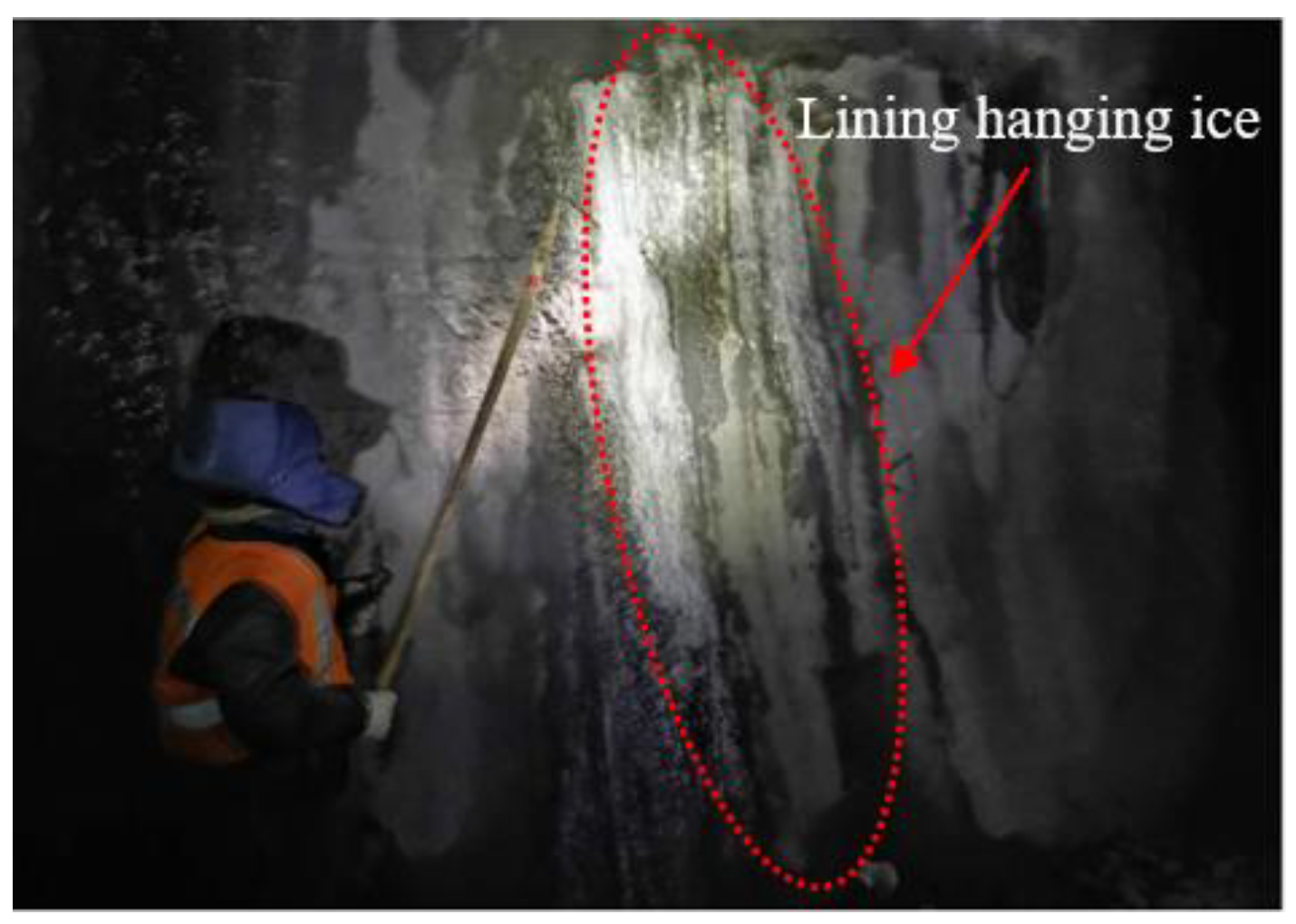
2.2. The Influence of Lining Rupture

After many years of operation, the waterproof layer of the tunnel lining will inevitably undergo the phenomenon of aging and cracking. In the case of tunnel leakage, especially in winter, the phenomenon of lining ice hanging frequently occurs, as shown in Figure 2 and Figure 3.
The ice column is formed on both sides of the tunnel, and the water drips from the top of the tunnel to form the ice column intrusion limit on the line, which endangers the security of driving and causes ground subsidence, as shown in Figure 4. In the long run, it is bound to be a condition for mud pumping in the ballast bed. If daily screening is ineffective, the drainage ditch in the tunnel lacks regular dredging, and the water in the tunnel cannot be discharged smoothly outside the tunnel; therefore, the occurrence and impact of this disease will be further aggravated.

2.3. Impact of Drainage Systems

The tunnel drainage system is gigantic, and the major causes of tunnel diseases can be attributed to the following points.
(1)
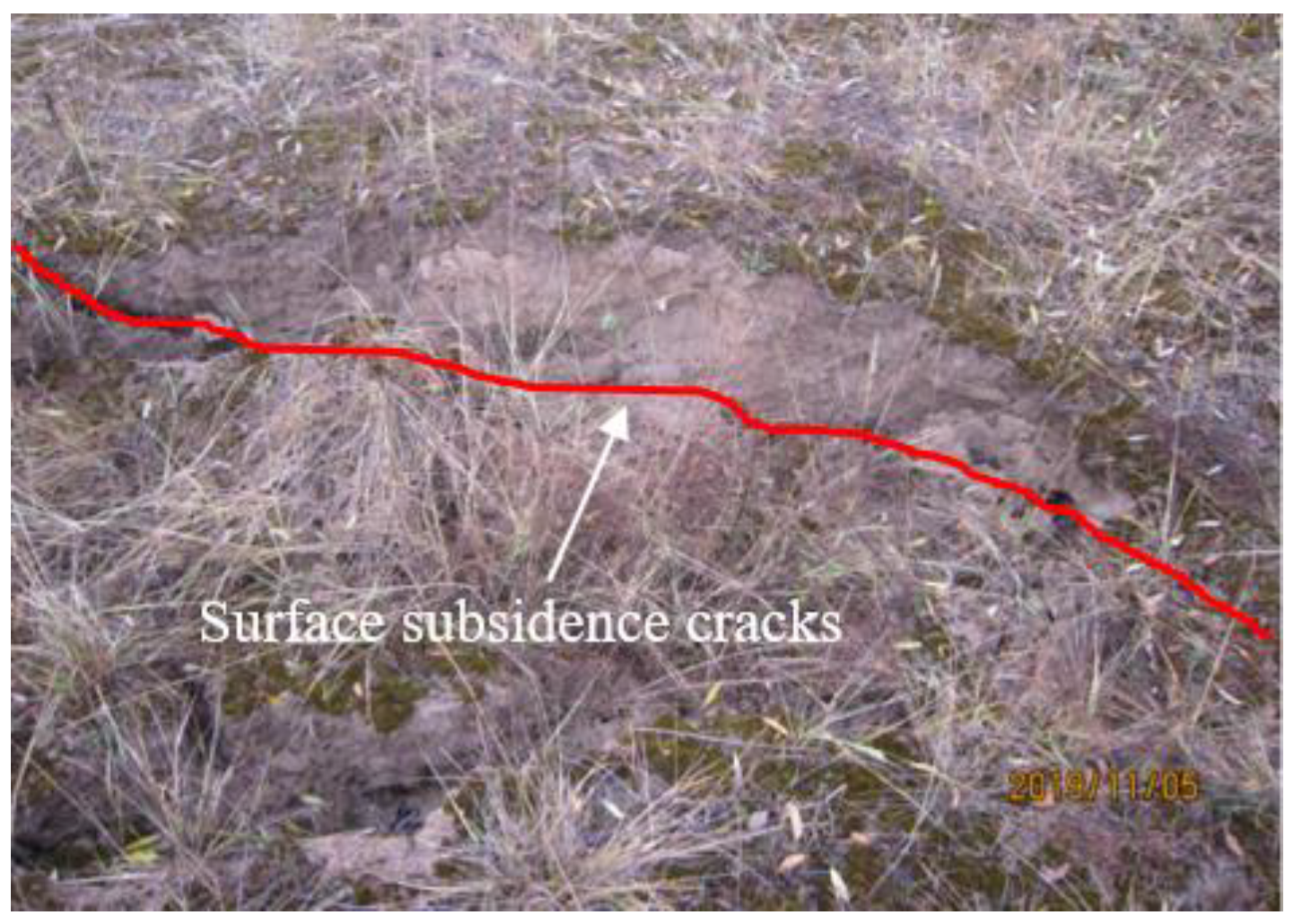
Formation reasons: the tunnel site area of the loess tunnel of the Lanzhou Bureau Group Company is primarily in a semi-arid climate, with a substantial seasonal temperature difference, a clear distinction between rainy and dry seasons, and concentrated surface precipitation. The tunnel mostly passes through sandy loess layers, clay loess layers, and sand-layered soil. These conditions provide a preponderant space for the enrichment of groundwater. After rainfall, the groundwater level rises, and the groundwater continues to flow and accumulate at the bottom of the tunnel. Once there are cracks in the inverted arch, there will be water accumulation and mud pumping in the track bed. Poor geological conditions are the decisive factor for mud pumping in loess tunnels.
(2)
The blind tube cannot drain normally due to crystallization blockage and other related reasons, which cause the groundwater level around the tunnel to rise, resulting in leakage of water in the tunnel.
(3)
Non-standard construction of construction joints, expansion joints, settlement joints, structural connection parts, or concrete defect parts causes tunnel leakage.
(4)
Poor construction quality. The over-excavation part of the basement is backfilled with waste slag, which makes the tunnel bottom a weak foundation. Meanwhile, in the rail joint part, the impact force of the wheel is 5–10 times larger than that of the general part, which makes the rail joint part more prone to cracking and mud pumping.
(5)
The depth and width of the drainage ditch are not enough, and it is difficult to effectively dredge the water between the bottom pavement and the surrounding rock. Under the action of the trains’ dynamic loads and capillary siphon, the groundwater rises, causing the bottom pavement or concrete inverted arch to be broken. Furthermore, the mud is squeezed out, forming mud pumping.
(6)
Limestone ballast, due to its soft texture, low toughness, and high wear rate, creates bed hardening and serious fouling in operation, causing drainage channel obstruction and ballast water accumulation.
During the period from 2015 to 2022, the research group investigated the tunnel base diseases in the pipe section of Lanzhou Bureau. Some photos of typical findings are shown in Figure 5.

3. Common Measures and Key Technologies of Tunnel Mud Pumping Disease

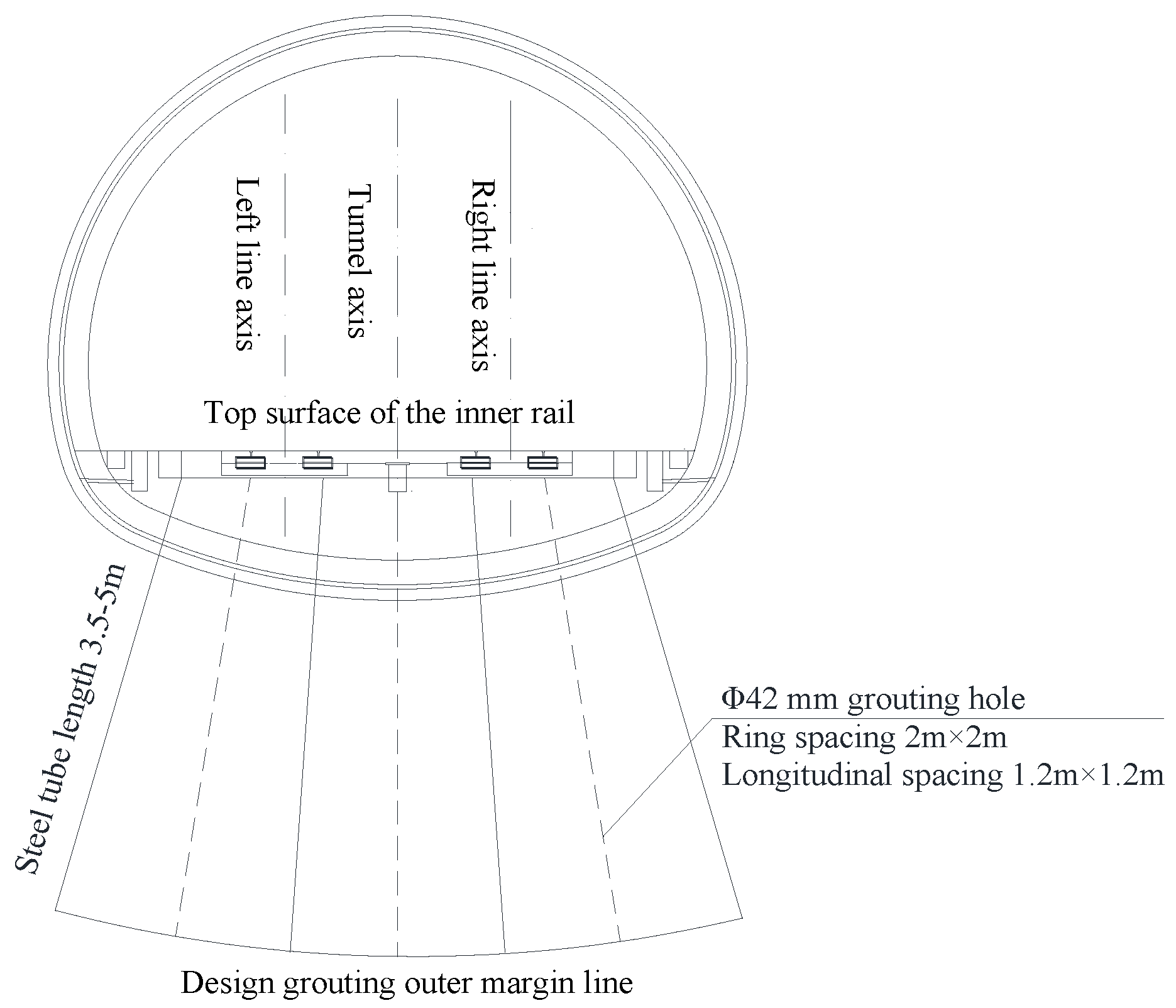
3.1. Grouting Reinforcement Technology

Grouting reinforcement is one of the most common methods to solve the problem of tunnel mud pumping [28], which is realized by splitting diffusion and extrusion packing of the surrounding rock by the slurry in the stratum [29,30].

3.1.1. Grouting Reinforcement Treatment Scheme

The grouting reinforcement of the tunnel base can be carried out by using a welded small pipe with a diameter of 42 mm and a wall thickness of 3.5 mm. The grouting holes are arranged in a plum blossom shape, and the longitudinal and circumferential spacing is 2 m × 2 m and 1.2 m × 1.2 m. PO 42.5 cement is selected as the cement: the water–cement ratio of the slurry should be 0.7:1–1:1, and the grouting pressure should be 1~1.5 MPa. The final injection condition is that the grouting pressure reaches 1.5 MPa and the duration is not less than 10 min [31]. A cross-section layout of tunnel base grouting is shown in Figure 6.

3.1.2. Key Technology and Process

Firstly, the technical parameters of grouting are preliminarily designed, and the pre-test design of the grouting technology is carried out in the test section to summarize the construction technology. After determining the grouting parameters and the corresponding supporting grouting equipment, it can be popularized and applied. Before the pre-test, it is necessary to effectively seal the bottom of the tunnel and set up oblique grouting holes at the secondary lining side wall. Especially, the grouting sequence should be longitudinally segmented and carried out according to the jump hole interval grouting method, and the grouting construction method of “first outside and then inside” should be adopted to avoid adjacent hole grouting and the invalid leakage of the slurry. After construction is completed, it is necessary to verify and accept the grouting construction process (the main control project has the slurry diffusion radius, the consolidation of the weak interlayer at the bottom of the inverted arch, the filling of the gap, the change of the bearing capacity of the basement, and the sealing of the leakage of the basement) [32].

3.1.3. Shortcomings of Technology

When grouting in the backfill thickness range and the outer range of the tunnel structure, there are problems such as extruded joint mortar in the surrounding area and difficulty in forming a grouting wall, which lead to many grouting problems found in the grouting process test, such as the qualified point of the grouting borehole stone rate, grouting defects, and other problems. In order to further grasp the current situation of the problem and determine the crux of the problem, the grouting range is divided into different grouting areas, of which the width of the surrounding area is 3 m, and the width of the sub-surrounding area is 6 m. According to the statistics of grouting reinforcement in the local area of tunnel mud pumping disease under the jurisdiction of the Lanzhou Bureau, it was found that the cavity mainly appears in the surrounding grouting area. In view of an in-depth analysis of the grouting construction process, it is considered that the poor forming of the surrounding grouting wall is the main reason, and the poor construction control technology, the small-rated pressure of the grouting pump, the lack of a retarding water reducer, the inappropriate selection of cement varieties, the large spacing of the grouting holes, and the incorrect end standard of single hole grouting are the secondary reasons. The reasons above generally appear in the grouting process and restrict this technology.

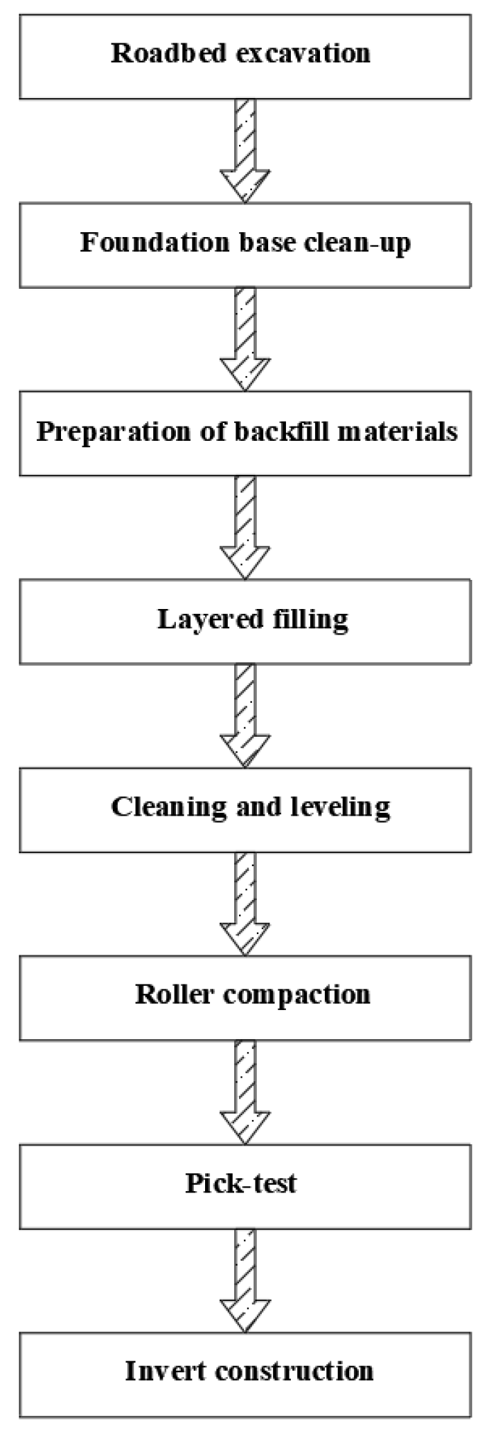
3.2. Inverted Arch and Bottom Pavement Replacement Technology

The technology was developed to effectively remove the soft soil composition of the tunnel base, backfill the original vacant part with excellent stability materials, and consolidate to achieve the purpose of enhancing the stability of the tunnel base.

3.2.1. Replacement Material

With the improvement of building materials and the continuous development of new materials with certain practicability, it is of great significance to carry out material replacement at the tunnel base and select economical, effective, and convenient materials [33].
(1)
Materials with a large pressure diffusion angle: the additional stress diffusion rate at the base is faster, which can reduce the top stress of the underlying layer and make the track bed safer.
(2)
It is economical to use pebble and gravel cushions, but the foundation’s bearing capacity is small, and the structure is unsafe, while the concrete cushion is the opposite.
(3)
Lime soil cushion: by mixing a certain amount of lime and water into the soil, it has perfect mechanical properties, water stability, and plate properties, thereby increasing the density of the substrate and improving its stability. The lime soil has wide material distribution, low cost, and high strength performance. The tunnel base has strong stability after replacement, which can meet tunnel engineering design standards.
Therefore, based on a comprehensive consideration of the geological conditions and the actual situation of the engineering project, lime soil can be used as the main material for replacing the foundation of the loess tunnel.

3.2.2. Determination of the Thickness of the Bottom Pavement Replacement Layer

By comparing the calculation and replacement technology of the subgrade bearing capacity in water-rich soft soil areas [34], the replacement depth of the loess tunnel base was determined. Under the premise of comprehensively considering the economy and meeting the bearing capacity of the loess tunnel basement, lime soil replacement technology was selected to treat the loess tunnel basement. The thickness of the lime soil replacement must meet the strength requirements of the underlying layer (meet the building foundation design specification GB 50007-2011 [35]).
P Z + P C Z f a z
In the formula, Pz is the additional stress value at the bottom of the cushion when the standard load combination is calculated by elastic theory or stress diffusion graph. PCZ is the self-weight stress of the soil at the bottom of the cushion and faz is the design value of the foundation’s bearing capacity after depth modification.
According to the geotechnical engineering geological survey report, the characteristic value of bearing capacity faz, the thickness of cushion, and the pressure diffusion angle of the cushion can be determined, and the thickness of the replacement layer can be calculated [36].
P Z + P C Z = b L ( P P C ) ( b + 2 Z tan θ ) ( L + 2 Z tan θ ) P s
In the formula, b is the width of the foundation bottom; L is the base length; P is the average pressure value at the bottom of the foundation under the standard load combination; PC is the self-weight stress of the soil at the bottom of the foundation; and Z is the thickness of the replacement layer. If there is no test data, when Z/b ≤ 0.25, θ = 20°; when Z/b > 0.50, θ = 30°; when Z/b ≤ 0.25, θ = 20°; and when Z/b > 0.50, θ = 30°. Ps is the design-bearing capacity value.

3.2.3. Key Technology and Process

This section outlines the production process of lime-stabilized soil. It is necessary to ensure complete digestion within 3–5 days before the use of lime. Subsequently, break the soil block to ensure its maximum length is below 1.5 cm. When paving with soil and lime, it is necessary to spread the loose soil first and determine the materials reasonably according to the volume ratio. Before mixing the construction materials, a detailed inspection of the soil moisture content is necessary to determine the optimal moisture content. Wet air drying and dry spraying are carried out, and two initial mixes are carried out first. Then, according to the changes in moisture content, multiple mixes are carried out again until uniform mixing is achieved. Meanwhile, strictly follow the pre-arranged construction plan and carry out construction operations in an orderly manner during the construction process. Firstly, the water and silt near the diseased section of the tunnel are cleaned. Excavate to a defined replacement depth, then flatten and compact the bottom. In particular, artificial excavation should be used as much as possible in tunnel base excavation to reduce soil disturbance. Ensure the smoothness of the waterproof material laid, especially the sealing of the joints. Immediately following, the lime soil material is layered and filled to the necessary elevation; the thickness of each layer is controlled at 20–30 cm, and the compaction is repeated layer by layer. In the construction process, great importance should be attached to the dynamic effect of vibration compaction when paving the materials, as this effect will damage the tunnel structure. Therefore, it is necessary to optimize the construction organization reasonably to avoid resonance and reduce the influence of the base replacement construction on the tunnel itself. Moreover, in the construction, it is necessary to add monitoring points to strengthen the horizontal convergence and settlement monitoring of essential parts of the support. For sections with a prominent deformation rate, temporary reinforcement measures, such as adding steel pipe vertical supports, should be taken to ensure the safety of the tunnel itself during the construction process. The construction technology of the inverted arch and bottom pavement replacement for loess tunnel foundation mud pumping is shown in Figure 7.
The designs of the inverted arch and bottom pavement replacement are shown in Figure 8.

3.2.4. Technical Deficiencies

Considering the limitation of tunnel space, the tunnel base replacement under the jurisdiction of the Lanzhou Bureau adopts a sinking overhead scheme. Under the condition of ensuring the track geometry, line stiffness, and stability after the line is overhead and ensuring the safety of heavy haul freight trains, taking into account the actual situation of narrow space and the difficulty in handling bulky cargo during on-site operation, the weight and length of the single component of the construction beam should be controlled as much as possible during the construction. However, its construction is difficult because of the need for overhead lines, which require the speed limit of the train to pass, which has a certain impact on the operation.

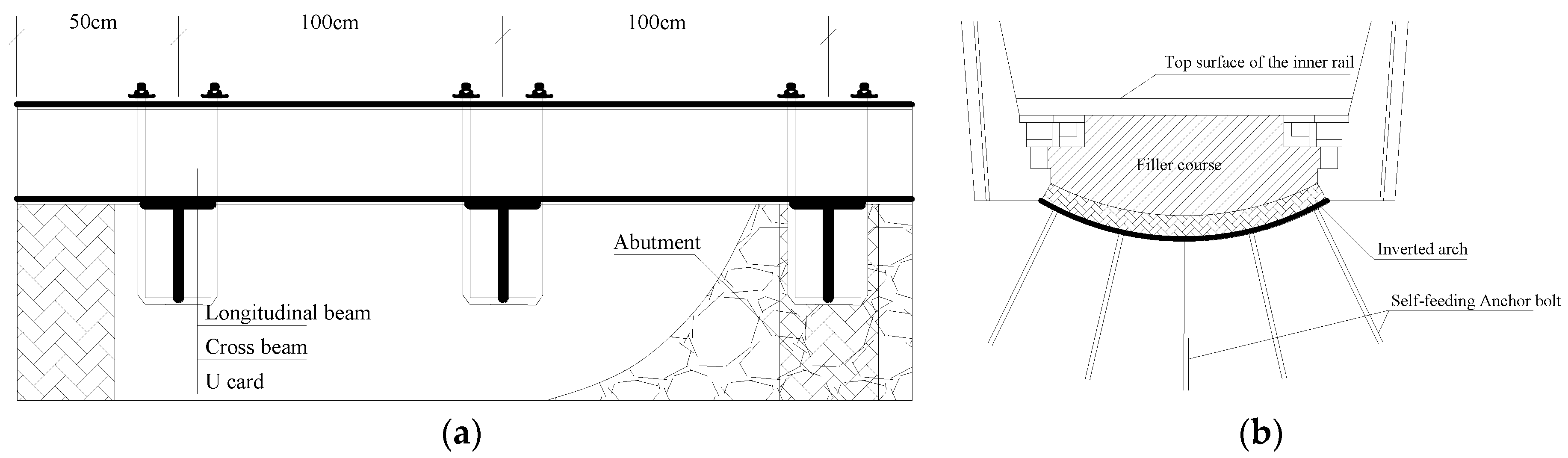
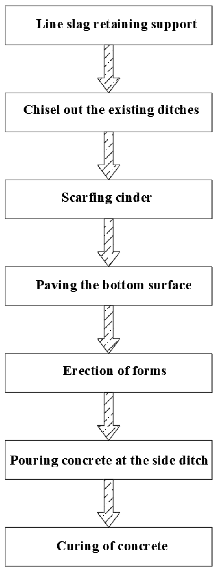
3.3. Deepen Side Ditch Technology

The existing tunnel drainage ditch is deepened, and when adjusting the position of the ditch, it is reasonably planned so that the water level is lowered. Furthermore, the water in the track bed is discharged into the side ditch, and the water in the track bed at the bottom of the tunnel is reduced to solve the problem of mud pumping at the bottom of the tunnel.

3.3.1. Key Technical Indicators

The purpose of deepening the side ditch is to prevent the water in the side ditch from flooding into the track bed, which involves the adjustment of the position of the ditch and the deepening of the side ditch. For a tunnel section with an inverted arch or a double-line non-inverted arch tunnel, it is necessary to consider that the tunnel ditch needs to be connected longitudinally along the whole line. Because the closer to the tunnel center line, the thicker the base filling, the side ditch is buried in the filling layer and needs to be close to the side of the road center line. Therefore, the position of the inverted arch side ditch and the drainage ditch cable groove is changed, and instability of the tunnel side wall foundation due to the excessively deep ditch is avoided. Concretely, the key index to reflect the water level of the drainage system is the height difference between the top surface of the rail and the drainage ditch in the tunnel, which is set as D. If this value is too large, it will inevitably increase the number of projects and the difficulty of construction to deepen the side ditch. The construction blocking time for the operating line is short, only 1–2 h, because it causes a waste of funds. If the D value is too small, meaning that the groundwater level is higher than the bottom of the track bed, it cannot solve the problem of mud pumping. Therefore, in the design, the D value must have a reasonable range.
Liu and Wang [37] considered that the reasonable range of D should be 1.15 m ≤ D ≤ 1.55 m through a comparative study of the anteroposterior renovation of the tunnel. You [38] provided a calculation formula for the bottom elevation of the deepened side ditch based on the general reference map of tunnel construction.
H0 = H − a − h
In the formula, H is the base elevation; H0 is the bottom elevation of the side trench; a is the reserved safe distance, generally 15 cm; and h is the maximum water depth of the side ditch, generally 25 cm. After deepening the side ditch, if the elevation of the ditch bottom is lower than that of the inverted arch bottom, 10 cm of bottom laying should be carried out at the bottom of the deepening ditch.

3.3.2. Construction Process

When the trench is excavated, it is necessary to excavate at the designed skip interval and pour promptly. Over-excavation is strictly prohibited at the bottom of the side wall to ensure the stability of the foundation. It should be noted that each excavation should be less than 5 m, and the spacing of each groove should not be less than 15 m. The demolition of existing ditches and the excavation of grooves should be performed by manual and pneumatic machinery [39,40]. During the excavation of the drainage ditch, the pit wall is supported to ensure the stability of the line. After the excavation of the foundation pit, it is necessary to clean up the debris in time and use the train gap to manually clean up the spoil. The spoil is temporarily stacked on both sides of the sidewalk and must not invade the limit. When there is a closed time period, the spoil is loaded and transported out. Moreover, the ditches are interlaced and excavated, and the construction is concentrated in sections. Strictly control the excavation distance and the length of the down-tube. Complete the pouring operation as soon as the excavation is carried out. Minimize the exposure time of the foundation pit. Furthermore, if there is water in the trench excavation, the water should be drained, and the concrete poured in time. The process flow of deepening the side ditch to treat the mud pumping disease of the loess tunnel base is shown in Figure 9, and the rectification design is shown in Figure 10.

3.3.3. Technical Deficiencies

The construction technology of deepening the side ditch to treat the mud pumping disease of the loess tunnel is simple, and the disturbance to the line is minimal, which makes it convenient to organize the construction during the operation period. However, due to the thin wall of the side ditch, the overall strength is low. When the track is changed and the sleeper is replaced in the tunnel, the side wall is easily destroyed. The side ditch walls are all concrete, leaving only a few drainage holes. Once a drainage hole is blocked, it will affect the smooth discharge of water in the ballast bed. When passing through the inverted arch section, if the inverted arch is not destroyed, the depth of the ditch often fails to meet the requirements and cannot reduce the groundwater. If the inverted arch is cut off, the overall stability of the tunnel structure is destroyed. Because of the shortcomings above, its application scope is narrow.

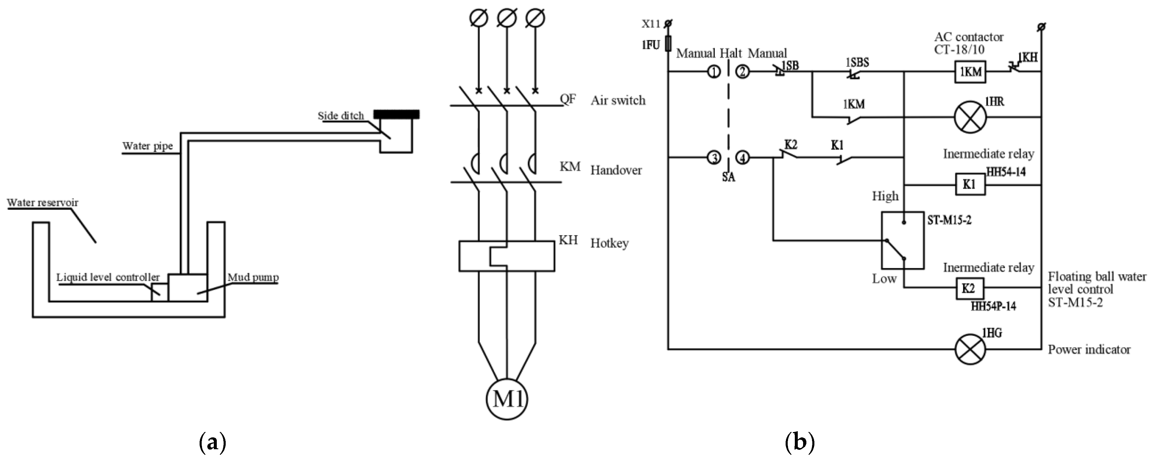
4. The Key Technology of an Additional Drainage Tunnel–Self-Priming Pump to Deal with Mud Pumping Disease

4.1. Renovation Mechanism

The window is opened on the lining of the side wall at the center of the disease, and the drainage tunnel is excavated at a certain safe distance from the side wall of the tunnel. Concretely, the drainage tunnel is generally set on the side of the groundwater, which is parallel to the tunnel and 3–4 m below the rail surface in the tunnel. Moreover, the drainage ditch and reservoir are set up in the discharge tunnel, and the underground water is collected and discharged by the buried pipe of the tunnel base and the surrounding rock outside the lining. The water volume and head height behind the tunnel lining are reduced, and the waterproofing and drainage pressure of the tunnel are decreased to drain the groundwater around the main tunnel. When the water level in the reservoir reaches a certain level, the self-priming pump is automatically started to drain the water to the tunnel’s side ditch. The principle of a self-priming pump is shown in Figure 11. The layout of the discharge tunnel is shown in Figure 12.

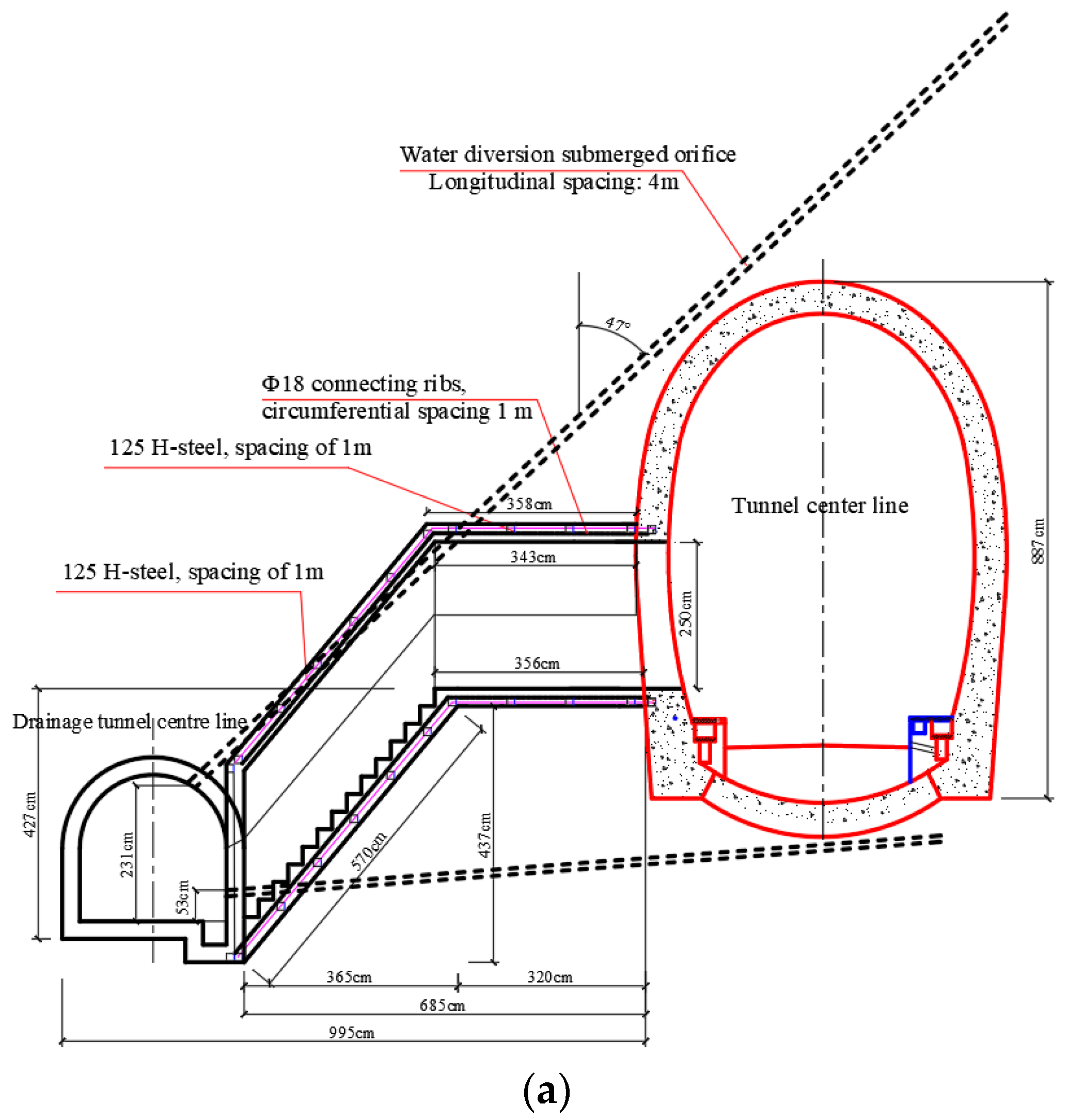
4.2. The Key Technology and Process

The key process flow for the construction of an additional discharge tunnel is shown in Figure 13.

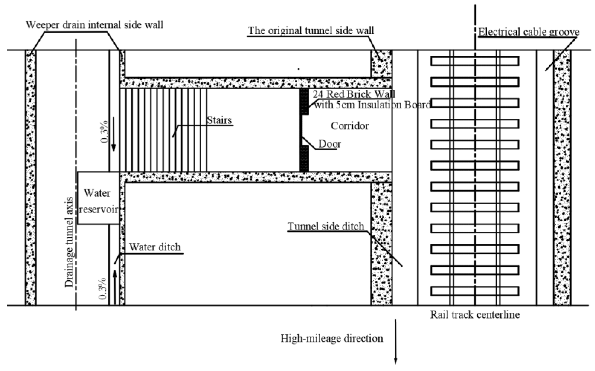
4.2.1. Chisel Connection Channel Window in the Refuge Recess

Firstly, a coring machine is employed to drill holes in the concrete lining, and the concrete between the holes is broken by a bench drilling machine, a pneumatic pick, or an electric hammer, as shown in Figure 14.

4.2.2. Excavation Method and Mucking

The discharge tunnel is excavated manually by the bench-cut method, and over-excavation and under-excavation are strictly controlled. The excavated muck is loaded into a woven bag and transported to the outside of the tunnel by a self-made flatbed truck, as shown in Figure 15.

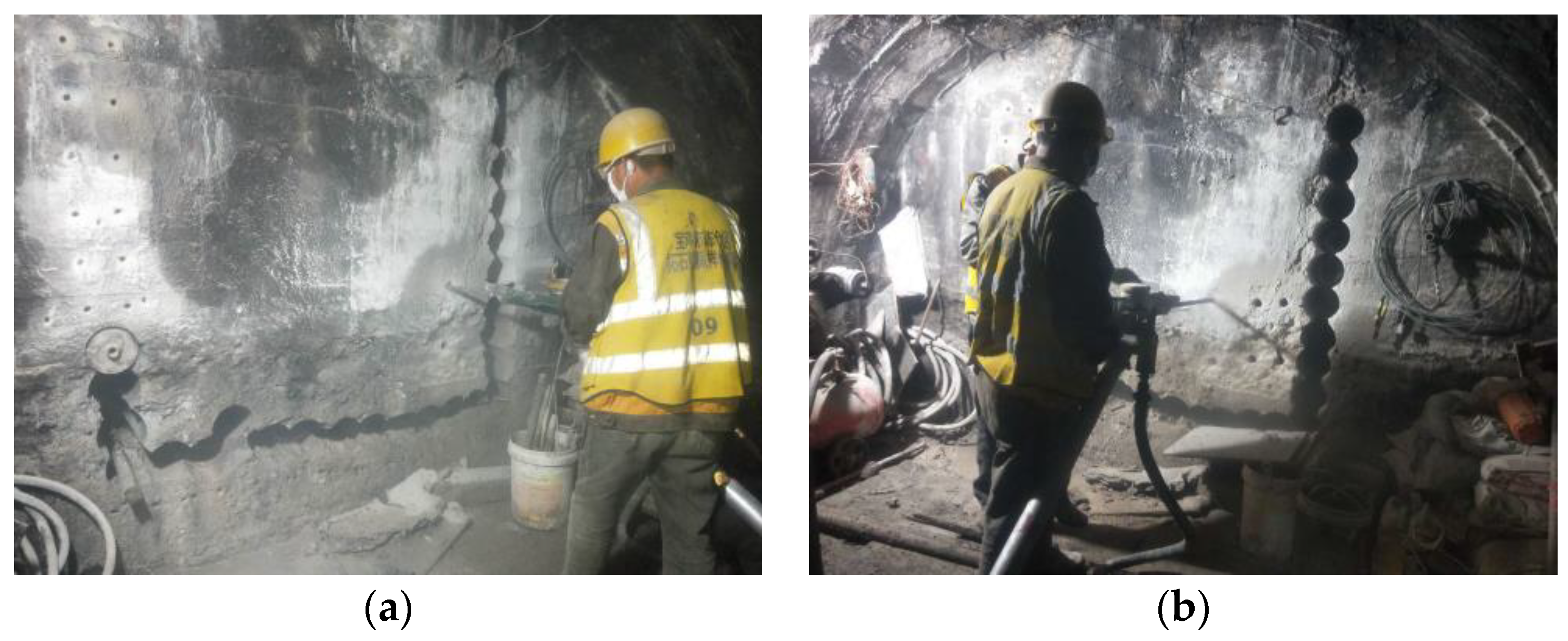
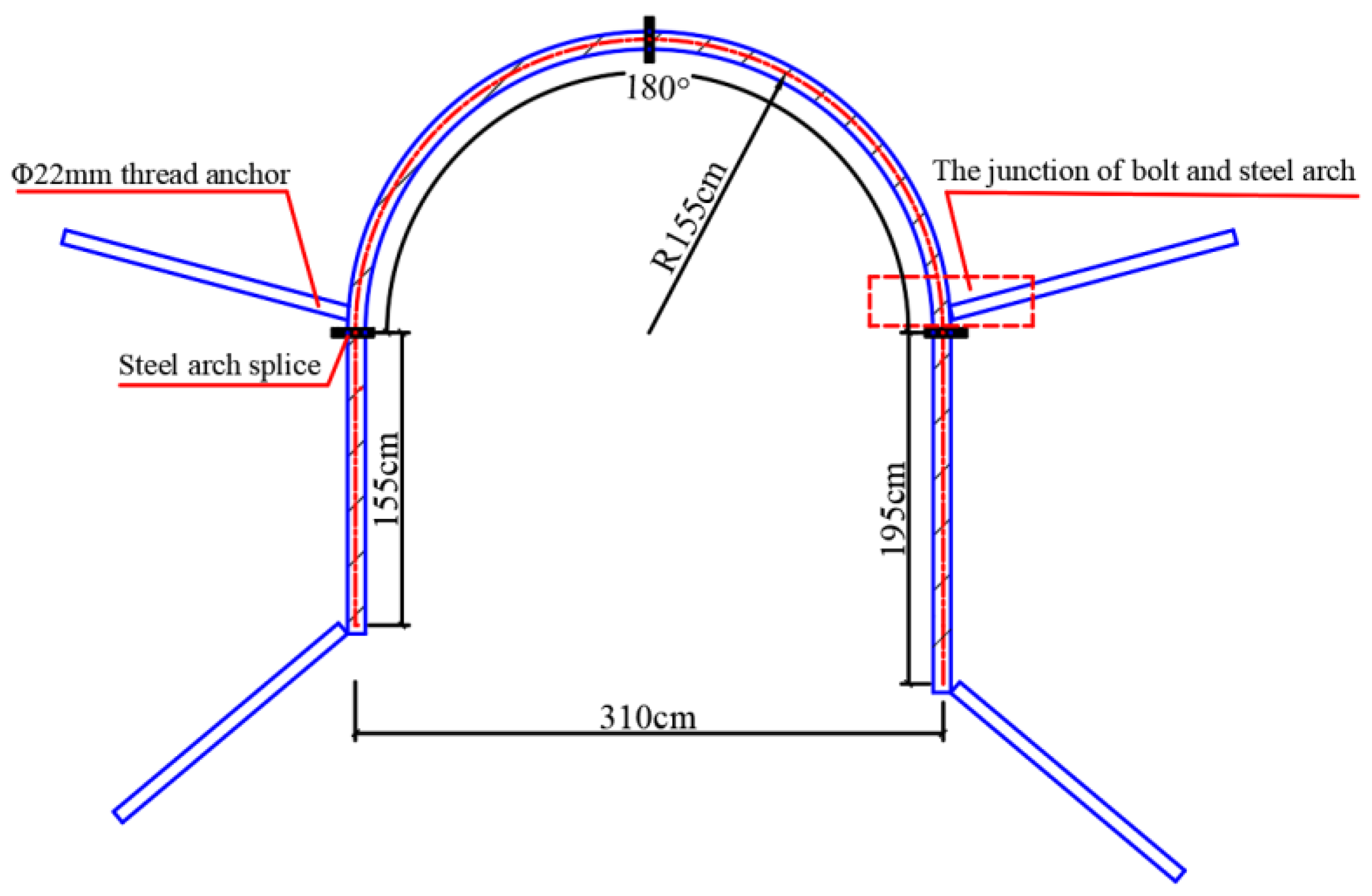
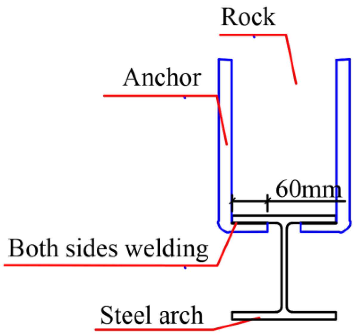
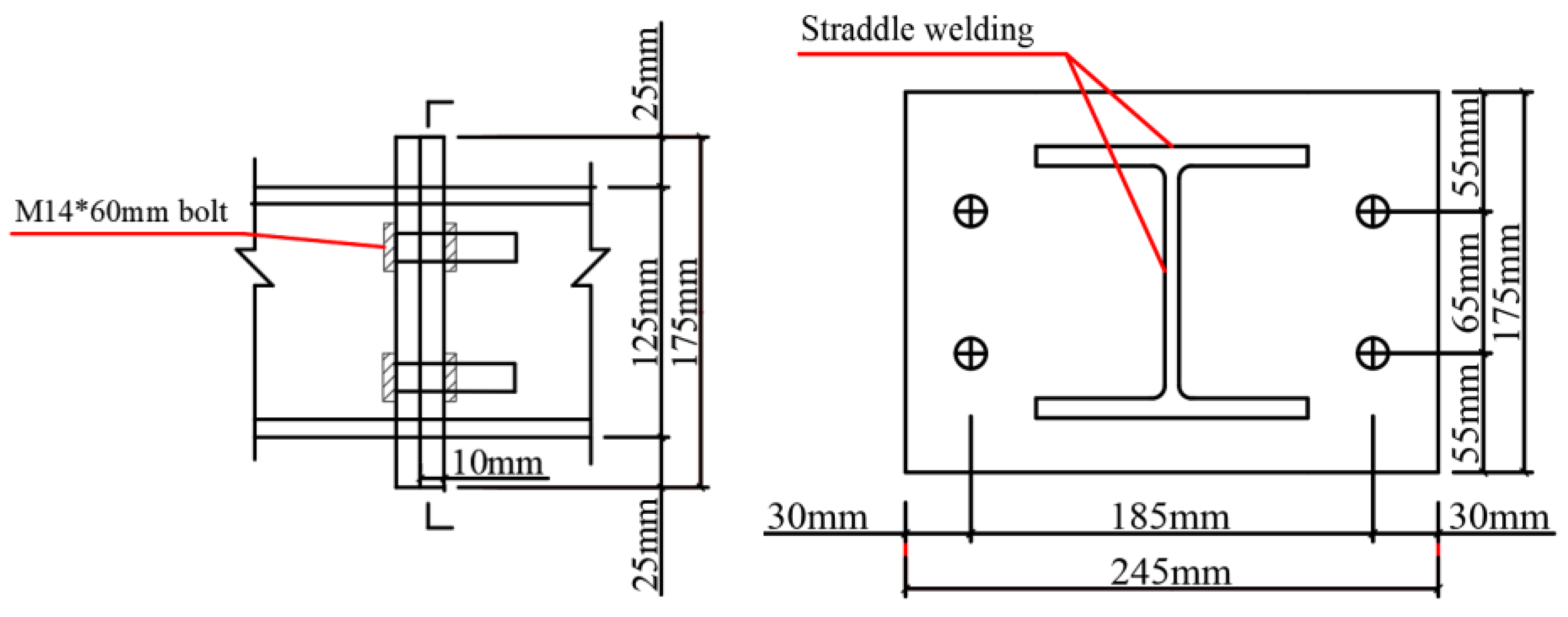
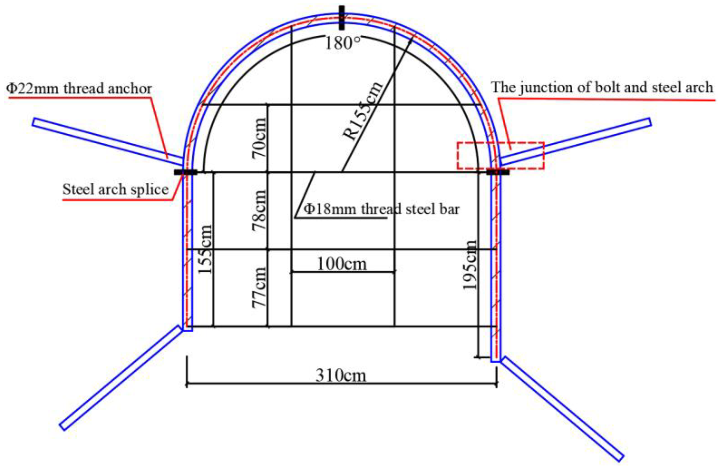
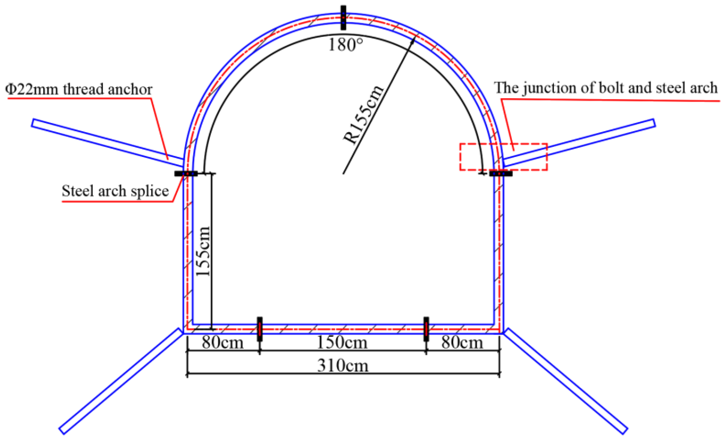
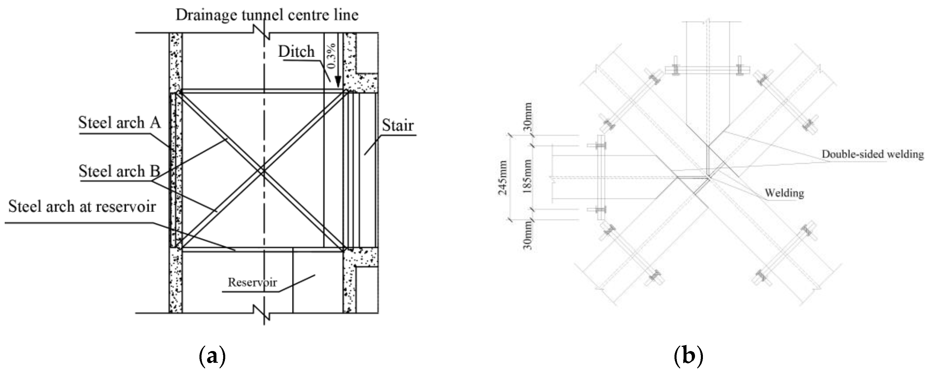
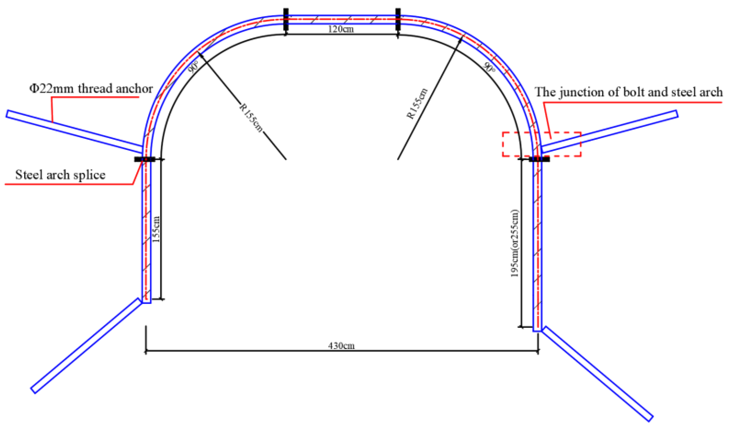
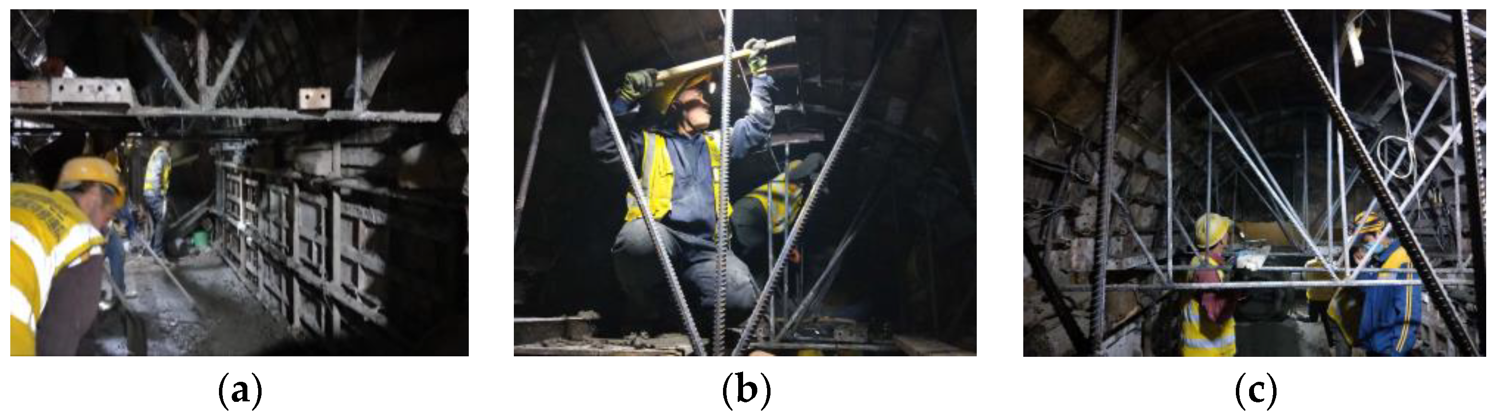
4.2.3. Construction of Steel Arch

(1) The steel arch frame of the discharge tunnel is designed and processed into sections outside the tunnel according to Figure 16 and connected into a hole with bolts, according to Figure 17, in the tunnel. The locking anchor rod is connected to the steel arch frame, as illustrated in Figure 18.
(2) The steel arch and steel bar of the end wall of the discharge tunnel are connected according to Figure 19.
(3) Connect the channel steel arch frame, as shown in Figure 20, outside the hole, according to the design process, into segments, in the hole with bolts connected into a hole.
(4) Connect the steel arch and steel bar of the end wall of the connecting channel according to Figure 21.
(5) The steel arch at the junction of the discharge tunnel connection channel is connected according to Figure 22. The steel arch at the reservoir of the discharge tunnel is connected according to Figure 23. The A and B steel arches of the connection channel of the spillway tunnel are connected according to Figure 24.
(7) The Φ8 20 × 20 cm steel mesh is installed after the anchor is applied. The steel is processed into a mesh outside the tunnel, and the diameter of the steel bar and the spacing of the mesh are in accordance with the drawings. The connection between the steel meshes and the connection between the steel mesh and the anchor rod are tied or spot-welded together with fine iron wire. The gap between the steel mesh and the supported rock surface is about 3 cm.
(8) In the process of installation, the two rows of steel frames should be connected with φ18 longitudinal steel bars every 1 m along the periphery to form a longitudinal connection system to improve the stress state.
(9) Arch springing must be placed on a solid foundation and erected vertically midline when the gap between the arch and the surrounding rock is too large when the setting block is placed. It is necessary to strengthen the arch foot and make the locking anchor pipe. If the surrounding rock at the arch foot is weak, necessary measures should be taken, such as increasing the locking anchor pipe, expanding the arch foot, and increasing the cushion plate, to ensure the stability of the steel arch.
(10) The φ22 cement cartridge lock foot bolt is adopted, and the construction process of the lock foot bolt includes drilling, hole cleaning, and bolt construction. According to the design requirements, the anchor hole is drilled. After reaching the standard, the hole is cleared with high-pressure air, and the processed cartridge is first put into the hole, and then the rod body is punched into the hole.

4.2.4. Form Concrete

(1) The small area steel formwork and shaped steel bulkhead of 100 cm × 30 cm × 5 cm are utilized in the outer formwork, and the reinforcement and support are carried out by using steel bars and steel tube square wood. The outer formwork should have a certain rigidity, dense splicing, and powerful support, as shown in Figure 25. The inspection focuses on the template gap and supports firmness to avoid extruded joint mortar and the template falling off. The end molds on both sides also require dense splicing and tough support. In addition, the end molds at the door are particularly crucial to ensure that the position is correct and smooth after pouring.
(2) The contact surface between the formwork and concrete must be cleaned and brushed with an isolation agent.
(3) Before pouring the concrete, water and debris in the formwork should be cleaned.
(4) C30 concrete material requirements are as follows: fine aggregate using hard, clean medium sand or coarse sand, fineness modulus greater than 2.5; coarse aggregate adopting hard and durable gravel, particle size not more than 15 mm; and gradation. In particular, alkaline accelerators should not use stones containing active silica; water does not contain harmful impurities that affect the normal setting and hardening of cement.
(5) The forced mixer is used for mixing the mixture; the mixing time is not less than 2 min. The weighing error of the raw materials is cement and accelerator ±1%, sand ±3%. The transportation time of the mixture shall not exceed 2 h.
(6) The concrete of the formwork lining adopts artificial vibration to ensure the internal and external quality of the concrete.
(7) When the concrete strength reaches 5 MPa, the formwork can be removed. In addition, if the formwork is subjected to considerable surrounding rock pressure, the concrete strength at the time of demolition should reach 100% of the design strength.
(8) The temperature of the concrete at the beginning of curing should be determined by thermal calculation according to the construction scheme, but not less than 5 °C, and the temperature of a thin-section structure should not be less than 10 °C. The temperature difference between the concrete and the environment should not be greater than 15 °C. When the temperature difference is above 10 °C but lower than 15 °C, temporary coverage measures are taken on the concrete’s surface after removing the formwork. The maintenance system should be determined by experiments and the relevant regulations. For concrete heated by an external heat source, when the ambient temperature is still below 0 °C after curing, the formwork can only be removed after the concrete is cooled to below 5 °C and the temperature difference between the concrete and the environment is not greater than 15 °C.
(9) Watering spray maintenance should be carried out in time after demolding, and the maintenance time should be no less than 7 days.
(10) During the construction of the tunnel, the construction water and drainage are strictly managed to avoid the phenomenon of construction water exposure and overflow during the construction period, which affects the surrounding rock of the tunnel.

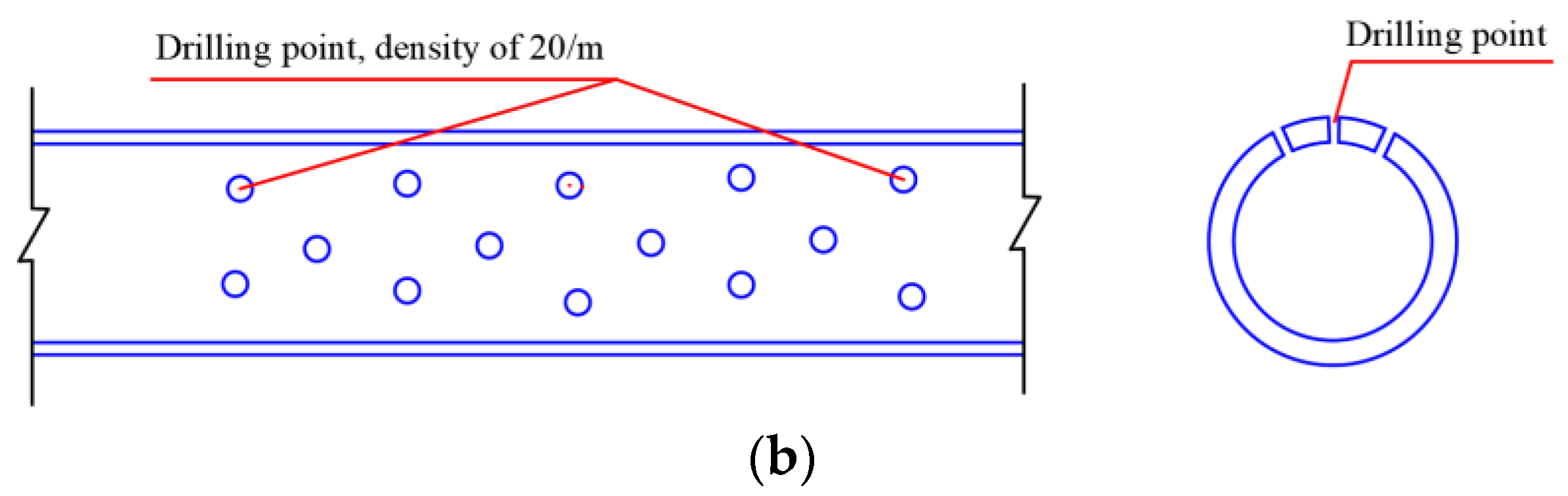
4.2.5. Down-Hole Construction

Down-holes are drilled according to Figure 26. A down-hole is drilled from the drainage ditch of the discharge tunnel, and then a polyethylene pipe is introduced into the down-hole and fixed. The lined water diversion pipe in the dive hole is a Φ70 high-pressure polyethylene pipe. A Φ5 mm permeable hole is drilled on one side of the pipe, and the hole density is 20/m. The PVC pipe is wrapped with a double-layer chemical fiber filter cloth to prevent sand and clay from flowing into the pipe [41,42]. The angle between the submersible hole and the horizontal at the side wall and the arch is 47 degrees, the length is 19 m, and the longitudinal spacing of the submersible hole is 4 m. The angle between the down-hole below the inverted arch and the horizontal is 5 degrees, the length is 12 m, and the longitudinal spacing of the down-hole is 2 m, as shown in Figure 27.

4.3. Comprehensive Comparison and Analysis

Through the summary of the key technologies and construction techniques of the four commonly used measures to control the mud pumping disease of the tunnel base, the advantages and deficiencies of each treatment scheme were compared and analyzed, as shown in Table 1.
The practicability of the four treatment schemes is summarized in Table 2.

5. Application Example

5.1. Songshuwan Tunnel

The Engineering Department of Lanzhou Railway Bureau Group Co., Ltd., which is located in Lanzhou, China; the Dingxi Engineering Section, which is situated in Dingxi, China, and the Lanzhou Jiaotong University Design and Research Institute Co., Ltd., which located in Lanzhou of China, jointly arrived at the Songshuwan Tunnel on the Longhai Line in November 2019 for an on-site disease investigation. The tunnel is a single line, built in 1960, with a total length of 2224.3 m. The current situation of the disease is due to complex surface and underground hydrogeological conditions, abundant groundwater, and the influence of surface loess sinkholes, resulting in serious problems, such as tunnel leakage and mud pumping. The technology of an additional drainage tunnel–self-priming pump was adopted for treatment.
The windows were opened outward in the large and small refuge recess in the continuous extension of the serious leakage disease section, and a connecting channel was constructed. Then, the connection channel was constructed, and the discharge tunnel was excavated along the longitudinal direction of the tunnel, 7 m away from the side wall of the tunnel. In the discharge tunnel, the flow ditch and the reservoir were set up, the submersible hole was constructed, and the pipe was buried to drain the groundwater in the surrounding rock within the side wall and the arch to the discharge tunnel. When the water level in the reservoir reaches a certain level, the self-priming pump automatically started to pump the water to the side ditch to drain away.

5.2. Doujiagou Tunnel

The central mileage of Lonely Gully Tunnel on the Baotou–Lanzhou Railway is K892 + 209. It is a single-line tunnel with straight wall lining. The thickness of the arch ring is 60 cm, and the thickness of the bottom pavement is 10 cm. It was built in 1957 and has a total length of 564.6 m. The shallow layer of the surface is loess–sandy clay. The tunnel body mainly passes through the conglomerate layer, and the thickness of the vault rock layer is thin. The surface of the tunnel section is irrigated land. In recent years, the vault at the entrance of the tunnel has cracked, and the leakage of water has corroded the arch lining. In the rainy season and irrigation season, the drainage ditch in the 10 + 6~15 + 6 section of the tunnel is silted up with yellow silt, which needs to be cleared every 3 months. When the rainfall is significant, the silt comes out of the cover plate of the drainage ditch, and the mud is poured from the ballast bed, causing traffic safety hazards.
In March 2019, it was decided to excavate a drainage tunnel 3 m outside the side wall of the left side of the large refuge recess in the 13 + 5 section to carry out the drainage of the pilot hole to control the silt of the side drainage ditch and the mud pumping of the ballast bed. The small refuge recess on the right side of the 17 + 15 section was used to drain the water in the surrounding rock near the side wall of the dive chamber, and the dark groove drainage was applied on the left side of the 18 + 4~5 section.

5.3. Gorilla Bay No. 2 Tunnel

The central mileage of Gorilla Bay No. 2 Tunnel on the Baolan Line is K920 + 682 and was built in 1956. The total length of the tunnel is 802 m. The upper half of the geology is loess, the lower half is weathered rock, and the stone is loose. In 1982, it was found that the concrete bottom plate was broken in the cleaning and screening track bed of the line rail replacement overhaul. Due to the lack of understanding of the situation during construction, part of the concrete residue was removed, resulting in damage to the protective layer, and a large amount of groundwater infiltration (high sulfate ion content in the groundwater, causing significant corrosion in the concrete) eroded the track bed and drainage ditch. The problem is serious and poses a hidden danger to traffic safety. It was decided to take the grouting treatment base and excavate the drainage hole 3 m outside the side wall of the tunnel to carry out the method of drainage.
At present, the Songshuwan Tunnel, Doujiagou Tunnel, and Gorilla Bay No. 2 Tunnel all adopt the technology of an additional discharge tunnel and self-priming pump, which has achieved considerable benefits for tunnel disease control.

6. Discussion

The disease of tunnel mud pumping is becoming more and more prominent. It is necessary to shift from passive treatment to active prevention to gradually solve the problem of tunnel mud pumping at the root. By adding a discharge tunnel and supplementing with self-priming pump technology, the technology sets up a dive hole above and below the tunnel so that the groundwater in the surrounding rock flows into the discharge tunnel and discharges, always maintaining a small groundwater content to achieve the fundamental purpose of water discharge and pressure reduction, highlighting the governance characteristics of “groundwater should be dredged rather than blocked”. Although this technology can cure this disease, it also has some limitations. For example, it is difficult to bolt the arch at the beginning of the discharge tunnel and the connecting channel. The layout of submersible holes is generally uniform or dense, so some submersible holes will not work and cause some waste; in addition, the submersible hole maintains a continuous working state, and it will inevitably be blocked, so it needs to be replaced and repaired after several years.
A quantitative effect analysis needs to be further studied and clarified, and the submersible hole layout can be optimized, as can the research on the protection of the drain hole and the maintenance of the submersible hole under long-term operation. These will be the focus of follow-up research. Finally, it is worth noting that the application of any method should not be a single effort but be integrated with other applications to improve treatment of the disease.

7. Conclusions

(1) Failure of the tunnel drainage system and support structure is the basic reason for the mud pumping. The train load provides dynamic conditions for it, accelerates the damage to the tunnel structure, and further induces mud pumping.
(2) The commonly used tunnel mud pumping treatment measures were summarized, but the commonly used measures are generally aimed at the local water leakage and mud pumping diseases of non-loess tunnels. There are shortcomings in these measures for long-established loess tunnels. Therefore, it is proposed to add a drainage tunnel–self-priming pump technology to eradicate diseases, such as mud pumping, in loess tunnels.
(3) The advantages and deficiencies of the four technologies were analyzed. The analysis shows that although the cost of the construction of the discharge tunnel–self-priming pump method is high, it can reduce and maintain the small content of groundwater in the surrounding rock of the tunnel basement to solve the problem of mud pumping in the loess tunnel basement at the root.
(4) The existing successful cases of the Lanzhou Bureau Group Company are listed. Meanwhile, this research is expected to provide references for similar projects.
Furthermore, the mechanical mechanism of the technology and the quantitative expression of disease treatment will be carried out in the future.

8. Patents

Patent 1: Li Dewu, Qi Hongyun, Hua Yongli, etc. A method for treating the disease of mud pumping and mud pumping in the basement of local sections of existing railway tunnels. Gansu Province: CN114542182 A, 27 May 2022 (China patent).
Patent 2: Li Dewu, Qi Hongyun, Hua Yongli, etc. A new structure for the treatment of mud pumping in the local section of the existing railway tunnel. Gansu Province: CN214944427U, 30 November 2021 (China patent).

Author Contributions

Conceptualization, X.L. and K.L.; data curation, X.L. and Q.J.; formal analysis, D.S.; funding acquisition, Q.J. and D.L.; investigation, X.L., D.S., K.L., Q.J., D.L. and Y.F.; methodology, D.S. and D.L.; project administration, Q.J. and D.L.; resources, Q.J. and D.L.; supervision, K.L. and D.L.; validation, Q.J. and Y.F.; visualization, X.L., D.S. and Y.F.; writing—original draft, X.L.; writing—review and editing, X.L., D.S., K.L. and Y.F. All authors have read and agreed to the published version of the manuscript.

Funding

Funding was provided by China Railway Lanzhou Bureau Group Co., Ltd. 2020 Science and Technology Research and Development Program Foundation Projects (Grant No. 2020-41).

Institutional Review Board Statement

Not applicable.

Informed Consent Statement

Not applicable.

Data Availability Statement

The authors of this article hereby declare that the relevant data in this article are available upon reasonable request. The data are not publicly available due to privacy.

Conflicts of Interest

The author, Qiqi Jia was employed by the company China Railway Lanzhou Group Co., Ltd. The remaining authors declare that they have no known competing financial interests or personal relationships that could have appeared to influence the work reported in this manuscript. All authors have made important contributions to the content of the article. Each author has reviewed the content of the final submission and agreed to submit it. The authors declare that this study received funding from China Railway Lanzhou Bureau Group Co., Ltd. The funder had no role in the design of the study; in the collection, analysis, or interpretation of data, in the writing of the manuscript, or in the decision to publish the results.

References

  1. Tian, S.M.; Wang, W.; Gong, J.F. Development and prospect of railway tunnels in China (Including statistics of railway tunnels in China by the end of 2020). Tunnel Constr. 2021, 41, 308–325. [Google Scholar]
  2. Lee, I.; Yu, S.; Park, K.; Lee, S.; Kim, H. Clogging phenomenon and drainage capacity of tunnel filters. J. Kor. Geotech. Soc. 1999, 15, 3–18. [Google Scholar]
  3. Shin, J.H.; Lee, I.K.; Joo, E.J. Behavior of double lining due to long-term hydraulic deterioration of drainage system. Struct. Eng. Mech. 2014, 52, 1257–1271. [Google Scholar] [CrossRef]
  4. Hayashi, S.; Shahu, J.T. Mud pumping problem in tunnels on erosive soil deposits. Geotechnique 2000, 50, 393–408. [Google Scholar]
  5. Ma, L.; Yue, Z.R.; Feng, H.P.; Yang, Z.H. Investigation of mud pumping in heavy haul railway embankment and countermeasures. Rail. Stand. Des. 2015, 59, 51–54. [Google Scholar]
  6. Ding, Y. Investigation on the Characteristics of Subgrade Mud Pumping and the Mechanism of Fine Particle Migration in Heavy—Haul Railway; Central South University: Changsha, China, 2022. [Google Scholar]
  7. Wang, W.J. Remediation of water-immersed subgrade diseases from K100 to K294 of Baolan line. Subgr. Eng. 1986, 1, 89–92. [Google Scholar]
  8. Miao, L.Q.; Yue, Z.R.; Feng, H.P. Causes and prevention measures of mud pumping in existing heavy haul-railways subgrade. Anhui Archit. 2014, 20, 113+121. [Google Scholar]
  9. Fan, Y.J. Reason Analysis and Remedial Measures of Disease in Dabashan Tunnel in Xiangfan-Chongqing Railway; Southwest Jiaotong University: Chengdu, China, 2005. [Google Scholar]
  10. Chen, L.W. Analysis on the causes of tunnel diseases. Tunnel Constr. 2004, 2, 83–85. [Google Scholar]
  11. Zhu, W.T.; Li, L.Q. Analysis of the present situation and causes of the tunnel bed diseases. Mod. Tunnel Technol. 2001, 5, 42–44. [Google Scholar]
  12. Xue, X.H.; Su, Z.M.; Sun, Z.J.; Song, F. Analysis of the Tunnel Disease Considering the Unsaturated Loess Matric Suction Effects. Adv. Mater. 2014, 859, 182–185. [Google Scholar] [CrossRef]
  13. Peng, G.X. Treatment of mud-pumping in foundation bed of bozhai No.2 tunnel. Rail. Op. Tech. 1999, 4, 3–5. [Google Scholar]
  14. Chen, Z.H.; Zhou, Y.H. Comprehensive treatment of existing railway tunnel bed diseases. Rail. St. De. 2002, 4, 36–37. [Google Scholar]
  15. LI, X.D. Comparative Study on Reconstruction and Expansion Schemes of Existing Tunnels in Loess Area; Chang’an University: Xi’an, China, 2019. [Google Scholar]
  16. Wang, Y. Study on Treatment Measures for Basement Deformation of Collapsible Loess Tunnel; Lanzhou Jiaotong University: Lanzhou, China, 2019. [Google Scholar]
  17. Zhang, Y.T. On the main diseases and construction technology of Highway Loess Tunnel. Intell. City 2018, 4, 141–142. [Google Scholar]
  18. Ding, Z.M.; Yang, X.H. Disease cause analysis and treatment measures of a loess tunnel. J. Eng. Geol. 2009, 17, 138–144. [Google Scholar]
  19. Xu, X.Z. Mechanism analysis and treatment measures of railway tunnel bed disease in loess area of Northern Shaanxi. J. Highw. Transp. Res. Dev. 2015, 11, 17–19. [Google Scholar]
  20. Nie, Z.P.; Zhu, S.H.; Zhao, W.H.; Pan, J.J.; Tan, Y.H. Disease analysis and safety evaluation of a highway tunnel group. J. Hust. 2003, 20, 42–45. [Google Scholar]
  21. Hua, T.; Li, J.; Qi, L.Y.; Xiang, Y.N. Disease analyses and rectification proposals for Taoping Tunnel on Hou-Yue railway. J. Railw. Sci. Eng. 1999, 17, 98–101. [Google Scholar]
  22. Chabot, J.D.S.; Sandrone, F.; Gamisch, T. The Importance of Drainage System in Railway Tunnels and Possibilities to Reduce the LCC. Underground—The Way to the Future. In Proceedings of the World Tunnel Congress, Swiss Tunnelling Soc, Geneva, Switzerland, 31 May–7 June 2013; EPFL: Geneva, Switzerland, 2013. [Google Scholar]
  23. Fan, L.F.; Wu, Z.J.; Wan, Z.; Gao, J.W. Experimental investigation of thermal effects on dynamic behavior of granite. Appl. Therm. Eng. 2017, 125, 94–103. [Google Scholar] [CrossRef]
  24. Farhadian, H.; Katibeh, H. New empirical model to evaluate groundwater flow into circular tunnel using multiple regression analysis. Int. J. Min. Sci. Technol. 2017, 27, 415–421. [Google Scholar] [CrossRef]
  25. Li, P.F.; Liu, H.C.; Zhao, Y.; Li, Z. A bottom-to-up drainage and water pressure reduction system for railway tunnels. Tunn. Undergr. Sp. Tech. 2018, 81, 296–305. [Google Scholar] [CrossRef]
  26. Meng, X.H. Research on the treatment technology of mud pumping at the bottom of heavy haul railway tunnel. Rail. Eng. 2014, 6, 69–71. [Google Scholar]
  27. Wang, X. Research on disease investigation and remediation technology of heavy railway tunnels. Build. Struc. 2019, 49, 988–994. [Google Scholar]
  28. Lu, H.F.; Yin, J.L.; Liu, Q.S.; Cao, A.D.; Wei, A.C.; Zhang, K. A self-dissolved grouting reinforcement method for water-rich soft rock roadway. B Eng. Geol. Environ. 2022, 81, 256. [Google Scholar] [CrossRef]
  29. Zhang, Q.S.; Li, P.; Wang, G.; Li, S.C.; Zhang, X.; Zhang, Q.Q.; Wang, Q.; Liu, J.G. Parameters Optimization of Curtain Grouting Reinforcement Cycle in Yonglian Tunnel and Its Application. Math. Probl. Eng. 2015, 2015, 615736. [Google Scholar] [CrossRef]
  30. Zhang, J.P.; Liu, L.M.; Li, Y. Mechanism and experiment of self-stress grouting reinforcement for fractured rock mass of underground engineering. Tynn. Undergr. Sp. Tech. 2023, 131, 104826. [Google Scholar]
  31. Zhang, D.Y.; Liu, S.Q.; Guo, D.Y.; Li, Y.B.; Song, W.X.; Wang, Y.M.; Liu, Y. Pipe Piles and Key Stratum Modeling for Grouting Reinforcement of Mine Floors under Mining Disturbance and Microseismic Monitoring Evaluation. Sustainability 2023, 15, 9294. [Google Scholar] [CrossRef]
  32. Xiao, Z.L.; Wen, J.P. Study on grouting reinforcement technology of Tunnel bed. Jiangxi Build. Mater. 2014, 2, 215–220. [Google Scholar]
  33. Duarte, G.; Gomes, R.C.; de Brito, J.; Bravo, M.; Nobre, J. Economic and Technical Viability of Using Shotcrete with Coarse Recycled Concrete Aggregates in Deep Tunnels. Appl. Sci. 2020, 10, 2697. [Google Scholar] [CrossRef]
  34. Luo, G.C.; Liu, T.T.; Wang, Z.; Wang, S.H.; Shen, Z.X.; Qi, L. Subgrade Bearing Capacity Calculation and the Application Research of Gravel Cushion Filling Technology in Water-rich Soft Soil Area. Subgr. Eng. 2019, 2, 183–187. [Google Scholar]
  35. GB 50007-2011; Code for Design of Building Foundation. China Building Industry Press: Beijing, China, 2013.
  36. Gong, X.N. Handbook of Foundation Treatment; China Construction Industry Press: Shanghai, China, 2008. [Google Scholar]
  37. Liu, C.L.; Wang, J.Y. Cause analysis and treatment of mud-pumping in tunnel. Rail. St. De. 2002, 6, 48–49. [Google Scholar]
  38. You, J.Y. Discussion on prevention measures of mud boil in Fushui Railway Tunnel Foundation. Rail. Eng. 2014, 11, 90–93. [Google Scholar]
  39. Richards, J.A. Inspection, maintenance and repair of tunnels: International lessons and practice. Tunn. Undergr. Sp. Tech. 1999, 13, 369–375. [Google Scholar] [CrossRef]
  40. Li, X.Y. Technical requirements of tunnel treatment and mud-pumping. In Proceedings of the High-Speed Heavy Haul and Ordinary Railway Bridge and Tunnel Operation Management and Inspection and Repair Technology Conference, Beijing, China, 1 March 2010. [Google Scholar]
  41. Zhang, L.; Yang, C.Y.; Zhong, C.G. Discussion on the design of the drainage tunnel and lining structure of the high-speed railway karst tunnel. Water Resour. Hydropower Eng. 2020, 51, 44–48. [Google Scholar]
  42. Zhang, X.W. Construction method of tunnel discharge tunnel under high water pressure. J. Highw. Transp. Res. Dev. 2019, 15, 195–196. [Google Scholar]
Figure 1. Mud pumping disease of loess tunnel.
Applsci 14 00276 g001
Figure 2. Ice covering on lining.
Applsci 14 00276 g002
Figure 3. Bed icing caused by water leakage.
Applsci 14 00276 g003
Figure 4. Surface subsidence cracks.
Applsci 14 00276 g004
Figure 5. Typical schematic picture of mud pumping disease: (a) tunnel bed mud pumping under slope bottom; (b) the bottom of the side drainage ditch of the Laotougou Tunnel; (c) Gorilla Bay Tunnel No. 2 roadbed; (d) Doujiagou tunnel side drainage ditch; (e) Donggang Town Tunnel roadbed; (f) the wolf tongue tunnel bed.
Applsci 14 00276 g005
Figure 6. Cross-sectional layout of grouting at tunnel base.
Applsci 14 00276 g006
Figure 7. Process flow diagram of inverted arch and bottom replacement.
Applsci 14 00276 g007
Figure 8. Design diagram of inverted arch and bottom pavement replacement: (a) design drawing of crossbar beams for overhead line; (b) replacement design drawing.
Applsci 14 00276 g008
Figure 9. Construction process of deepening the side ditch.
Applsci 14 00276 g009
Figure 10. Deepened side ditch design drawing: (a) design drawing with inverted arch; (b) no inverted arch.
Applsci 14 00276 g010
Figure 11. Principle diagram of self-priming pump: (a) drainage diagram; (b) sewage pump management schematic diagram.
Applsci 14 00276 g011
Figure 12. Drainage tunnel renovation plan.
Applsci 14 00276 g012
Figure 13. Construction process of additional drainage tunnel.
Applsci 14 00276 g013
Figure 14. Side wall demolition: (a) perspective 1; (b) perspective 2.
Applsci 14 00276 g014
Figure 15. Excavation and slag discharge on site: (a) excavation and ballast soil bagging; (b) self-made flatbed trucks to transport bagged ballast soil; (c) self-made flatbed trucks carry bags of ballast soil to the centralized transfer point.
Applsci 14 00276 g015
Figure 16. Installation diagram of steel arch of discharge tunnel.
Applsci 14 00276 g016
Figure 17. Locking anchor pipe and steel arch connection diagram.
Applsci 14 00276 g017
Figure 18. Bolt connection diagram between steel arch segments.
Applsci 14 00276 g018
Figure 19. Steel arch and reinforcement of the end wall of the spillway tunnel.
Applsci 14 00276 g019
Figure 20. Installation diagram of steel arch of connecting channel.
Applsci 14 00276 g020
Figure 21. Steel arch and steel bar diagram of the end wall of the connecting channel.
Applsci 14 00276 g021
Figure 22. Layout of the steel arch at the junction of connecting passages of the discharge tunnel: (a) layout drawing of the steel arch at the junction of the connecting channel of the discharge tunnel; (b) the layout of the steel arch bolt connection at the junction of the connecting channel of the discharge tunnel.
Applsci 14 00276 g022
Figure 23. Installation drawing of steel arch at reservoir.
Applsci 14 00276 g023
Figure 24. Connection channel of A and B steel arches installation diagram.
Applsci 14 00276 g024
Figure 25. Erecting formwork and pouring concrete: (a) perspective 1; (b) perspective 2; (c) perspective 3.
Applsci 14 00276 g025
Figure 26. Down-hole position and high-pressure polyethylene pipe drilling point distribution map: (a) down-hole position; (b) high-pressure polyethylene pipe drilling point distribution.
Applsci 14 00276 g026aApplsci 14 00276 g026b
Figure 27. Longitudinal layout of submersible holes.
Applsci 14 00276 g027
Table 1. Comparison of advantages and disadvantages of four treatment schemes for mud pumping disease of tunnel foundation.
Treatment MeasuresSuperiorityDeficiencies
Grouting reinforcement technologyThe construction technology is simple and has little influence on the line operation.The operation risks and the costs are high, the construction period is long, and the water-plugging effect cannot be guaranteed.
Inverted arch and bottom pavement replacement technologyBased on disease treatment, the bearing capacity of the foundation can be improved.The cost is high, the construction time is long, and the overhead line is needed in the construction, which has a dramatic impact on the line operation.
Deepened side ditch technologyReduces the damage of groundwater to the surrounding rock of the tunnel basement.The construction period is long, and the damage to the tunnel side wall structure is significant. The drainage hole is easy to block, resulting in the disease not being cured.
Additional drainage tunnel–self-priming pump technologyCompletely solves the problem of mud pumping.High engineering cost
Table 2. Comparative analysis table of practicability of four treatment schemes.
Grouting Reinforcement TechnologyInverted Arch and Bottom Pavement Replacement TechnologyDeepened Side Ditch TechnologyAdditional Drainage Tunnel–Self-Priming Pump Technology
Project costModerateSmall (local circumstance)HighSlightly higher
The difficulty of constructionElementaryModerateDifficultModerate
Environmental impact degreeInfluentialModerateSlight influenceSlight influence
Disease treatment effectDeviation and non-thoroughgoingLocal treatment effect is effectiveDeviation and non-thoroughgoingCompletely effective in the section
Disclaimer/Publisher’s Note: The statements, opinions and data contained in all publications are solely those of the individual author(s) and contributor(s) and not of MDPI and/or the editor(s). MDPI and/or the editor(s) disclaim responsibility for any injury to people or property resulting from any ideas, methods, instructions or products referred to in the content.

