Article

Novel Aluminum Alloy Tailored for Additive Manufacturing: Structural Characterization and Qualification Perspectives

1
Magnaghi Aeronautica of MA Group Company, Engineering & Research Unit, Via Galileo Ferraris 76, 80146 Napoli, NA, Italy
2
Department of Industrial & Materials Science, Chalmers University of Technology, Rännvägen 2A, 41296 Göteborg, Sweden
3
Department of Materials Science and Engineering, KTH Royal Institute of Technology, Brinellvägen 23, 10044 Stockholm, Sweden
4
Aidro S.r.l., 21020 Taino, VA, Italy
5
Höganäs AB, Bruksgatan 35, 26339 Höganäs, Sweden
*
Author to whom correspondence should be addressed.
Appl. Sci. 2024, 14(11), 4647; https://doi.org/10.3390/app14114647
Submission received: 25 April 2024 / Revised: 12 May 2024 / Accepted: 22 May 2024 / Published: 28 May 2024
(This article belongs to the Special Issue Additive Manufacturing Technology and Applications for Aerospace)

Abstract

:

Featured Application

The paper demonstrates key structural characteristics of a novel aluminum alloy conceived for AM-based components in the aviation frame.

Abstract

The recent advances achieved in additive manufacturing (AM) technology demonstrate the potential to realize customized metal components, ensuring weight reduction opportunities. These benefits make AM attractive for high-cost aerospace applications, especially where high geometric complexity is required. In the context of an EU research scenario, the H2020 MANUELA (Additive Manufacturing Using Metal Pilot Line) project promotes the development of new technologies for design optimization by enabling the application of novel materials in AM. This paper illustrates recent advances in a new aluminum alloy (Al-HS1) with high strength emphasizing all of the characterization steps at the coupon level. This material has been employed in the re-engineering of a conventional hydraulic manifold using a powder bed fusion-laser beam (PBF-LB) process. Both the simulations and structural tests allowed for proving its compliance and technological maturity with industrial standards and applicable airworthiness requirements.

1. Introduction

1.1. AM in the New Technological Scenario

Rapid industrial advancements in technology are addressing innovative and simultaneously sustainable and cost-saving manufacturing solutions. Additive manufacturing (AM) is a digital fabrication method involving the realization of three-dimensional objects by building them layer upon layer and linked together one at a time. AM processes are classified into the following categories based on the feedstock, layer deposition technique, and raw materials: direct energy deposition (DED) [1,2,3], powder bed fusion (PBF) [4,5,6,7], material jetting (PolyJet) [8], binder jetting [9], material extrusion [10], VAT photopolymerization [11], and sheet lamination [12,13,14,15]. AM is currently proposed as an alternative technique for the 3D prototyping of geometrically complex shapes, creating or finishing components and parts in many sectors [16,17,18,19,20], especially in aerospace and automotive applications [21]. The main interest of the aerospace industry is oriented toward safe weight optimization methods to maximize the payload and reduce gas emissions. The aviation programs ACARE 2020 (Advisory Council for Aviation Research and Innovation in the EU) and Flightpath 2050 raise awareness of the need for “greening” via optimizing aircrafts’ fuel consumption and CO2 and NOx emissions over the course of the next several years [22,23]. The aviation sector should undergo demanding technological development to meet these targets, such as by incorporating cutting-edge materials, design methodologies, and manufacturing processes, all while maintaining rigorous standards for structural durability and safety. Currently, the main engineering task is the maximization of a material’s efficiency while improving the functional and manufacturing complexity, which may not always be achievable through conventional approaches. Establishing effective methods to ensure that dfAM (design for additive manufacturing) strategies are developed is the primary challenge faced by the industry. For this reason, worldwide standards are in place to sustain the certification of these new manufacturing procedures, defining a comprehensively accepted framework [24,25]. Several in-depth reviews have reported on the progress in the AM sector, particularly focusing on aircraft and spacecraft applications [26,27,28]. The benefits of AM have been investigated extensively in the aerospace industry for decades; for example, Boeing [29,30,31,32], Airbus [33,34,35,36,37,38], Embraer [39], and General Electric [40,41] employed AM techniques for the manufacturing and repair of several parts. Spaces agencies, such as NASA [42,43,44,45], Thales Alenia Space [46], and SpaceX [47], are currently exploring the feasibility of utilizing AM igniters, injectors, and combustion chambers on their rocket engines.

1.2. Materials for Metal AM in Aerospace

The range of materials suitable for AM is truly broad, from ceramics to metals and up to advanced composites. The authors’ interest revolves around the utilization of metallic alloys that have already been analyzed, as well as offering suggestions regarding the considerable implications for aeronautical equipment [48]. Stainless steels are often selected for many aerospace applications in which hardness and strength, especially at elevated temperatures, are required. Different classes of stainless steels, including austenitic (SS316L), precipitation hardened (PH), and martensite aged, exhibit good adaptability to the AM processes. Depending on the environmental conditions for which they are conceived, these metals can achieve high wear, corrosion, and oxidation resistances without specific surface treatments [49,50,51]. For this reason, they are used across components in heat exchangers, landing gear systems, hydraulic manifolds and actuators, engine and exhaust systems, and structural joints. Titanium-based alloys (Ti-6Al-4V, Ti–8Al–1Mo–1V and Ti–10V–2Fe–3Al) are ideal candidates thanks to their stability at high-temperatures and specific strengths for use in critical parts, such as compressor blades, hydraulic valves, and structural brackets [52]. They are used in cryogenic applications for rockets’ propellant tanks and are electrochemically compatible if coupled with PMCs (polymer matrix composites), which are extensively used in aerostructures [53]. Nickel-based alloys are, instead, preferred for working at elevated temperatures, such as in the case of gas turbines and engine parts (e.g., Inconel 625 and 718) and for precision applications (Invar) [54]. However, steels present the serious disadvantage of being inappropriate for weight-sensitive applications, while titanium alloys, although with a better resistance-to-weight ratio, are much more expensive and require longer lead times. The aerospace sector demands light-weight properties, with appreciable mechanical characteristics, making aluminum (Al) alloys highly sought after. Many Al alloys are not the best fit on their own due to solidification cracking and porosity formation. This can be enhanced thanks to AM techniques that offer the possibility of optimizing tailored materials for the proper end application. For example, AM-produced parts in Al alloys (7A77, 6061-RAM2, AlSi10Mg and Scalmalloy©) can offer higher strength and successful builds.

1.3. Scope of the Study

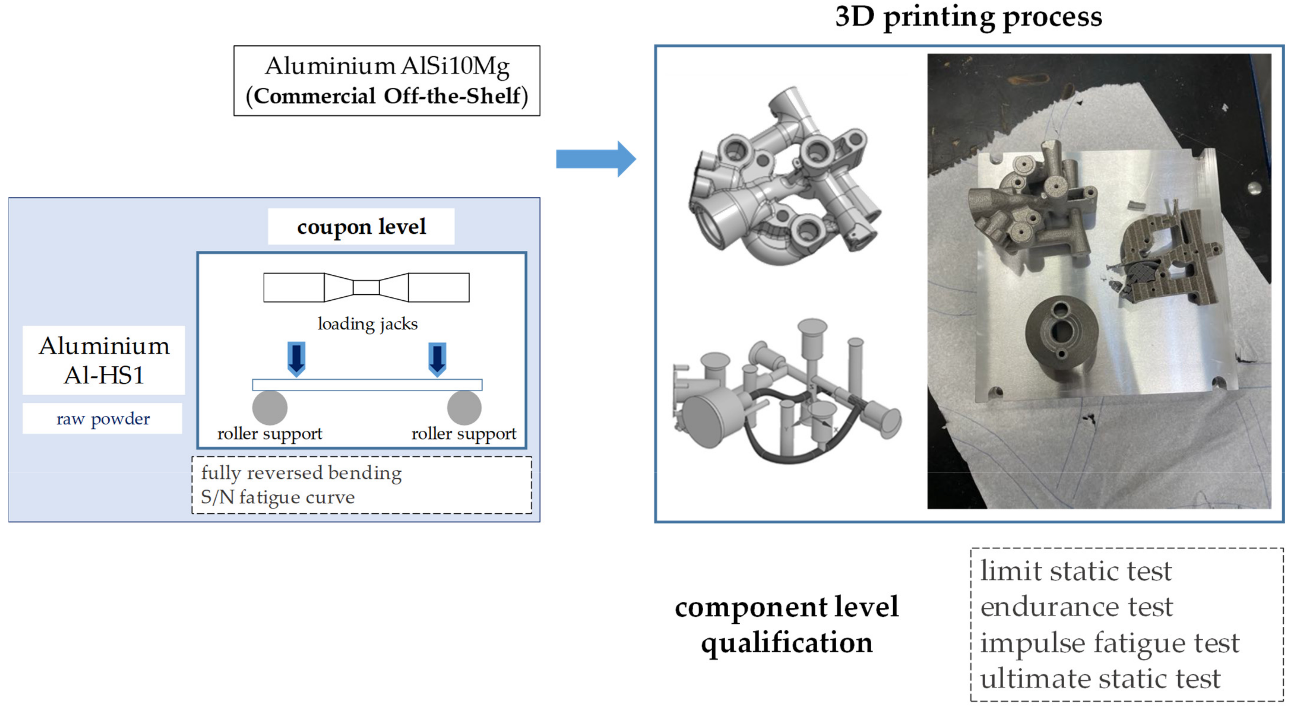
Therefore, Al alloys are among the most appropriate metallic materials for modulating their own physical properties in order to improve the structural and mechanical characteristics. The shorter lead time, reduced processing costs, lower specific weight, and greater availability on the current global market—compared to other alloys—constitute key points that the aeronautical sector considers in relevant strategic choices. In the context of seeking more suitable and innovative solutions for AM, in this article, the authors outline the recent findings on a novel Al alloy tailored for the powder bed fusion-laser beam (PBF-LB) process. This study was conducted as part of the MANUELA (Additive Manufacturing Using Metal Pilot Line) project funded by the European Union’s Horizon 2020 (grant agreement no. 820774); the material used was forAM® Al-HS1, which was developed for a PhD thesis in collaboration with Höganäs AB, Sweden [55,56]. After a digression on the microstructural properties of this alloy and its mechanical characterization as a standard coupon, the prospective of the material in question is demonstrated at the subcomponent level for aeronautical applications. As already discussed in a previous paper [57], a hydraulic manifold for landing gear applications was used as an adequate benchmark to substantiate the applicability of AM technologies. Manifolds are actually devices with very complex geometries developed to withstand both steady and cyclic pressure loads; for their intricate design features, hydraulic fatigue is a crucial point because of the occurrence of abrupt right-angle turns and very small radii in the internal ducts, which can potentially lead to premature cracks. Considering this perspective, higher strength alloys, such as titanium or steel, are often preferred for these items [58,59,60]. Additionally, the repeated high cooling rates that the AM parts generally experience during fabrication affect the fatigue life due to the presence of treating defects (in particular, microporosity and surface roughness). The dfAM thermal operations encompass recurrent solid-state phase transitions, which introduce residual stress and a crystallographic texture, usually consisting in epitaxial grain growth along the building direction. On the other hand, the static mechanical properties of AM metals are considered quite comparable to metallic components manufactured conventionally. The advantages of AM with an emphasis on fatigue behavior were demonstrated for a COTS (commercial off-the-shelf) Al alloy (AlSi10Mg) pursuing a typical step-by-step aeronautical qualification roadmap [57]. Herein, the authors highlight the huge potential of the novel high-strength Al alloys (Al-HS1 in particular) with respect to the same case study product; this activity allowed for enriching the experimental results with an in-depth characterization database. Following a typical building-block process, as shown in Figure 1, the new alloy, realized from a powder, was first characterized at the level of standardized coupons until its real validity was verified on a hydraulic subsystem for aeronautical interests (Figure 2).
The existing components in AlSi10Mg needed to be benchmarked, and, hence, it was considered important to compare these properties, even though the compositions of the materials are different. With respect to the standard AlSi10Mg, the new alloy has superior static characteristics in the plasticization regime, with the ultimate strength and fatigue life limits being comparable. The optimized version of the manifold was designed by AIDRO, Italy; printed by Chalmers University of Technology, Göteborg, Sweden, using the EOS M290 LPBF machine (Krailling, Germany [61]); and analyzed and qualified by Magnaghi Aeronautica SpA, Italy. The qualification and certification processes demonstrate AM is still challenging and point to the extent its adoption for primary structural components. Current procedures are too time-consuming and costly; therefore, feasible technological alternatives aimed at closing the gap between prototyping and industrialization maturity are necessary.

2. Materials and Methods

Various AM metal powder suppliers have recently enriched their offerings with high-strength Al alloys (for example, Elementum3D, M4P, and EOS); however, in most cases, the TRLs declared by manufacturers are still rather low. In the frame of this project, the raw material chosen was commercially available as forAM® Al-HS1, supplied in the form of gas-atomized powder, from Höganäs AB, Sweden. The particle size distribution for this material is 20–53 [μm]. The chemical composition of the powder is shown in Table 1.
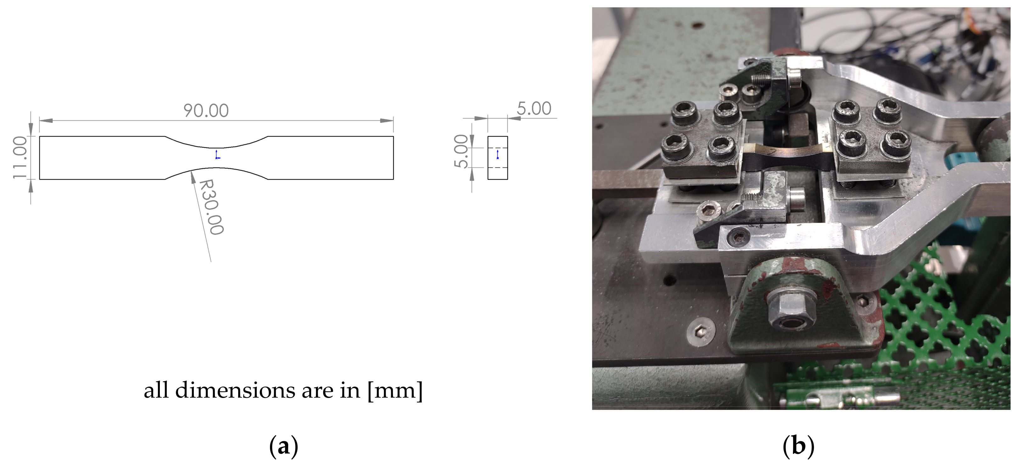
The raw material was processed in a PBF-LB machine (EOS M290, EOS GmbH, Krailling, Germany [61]) at Chalmers University of Technology, Sweden. All samples were produced with 370 [W] laser power, 1300 [mm/s] laser speed, 0.13 [mm] hatch distance, and 0.03 [mm] layer thickness. A scan rotation of 67° was applied between consecutive layers. These processing parameters led to >99.7% relative density, as discussed within [62,63]. All samples were cut directly from the build plate with a cold saw, and 10 [mm] side cubes were produced for the microstructural analysis. The bending fatigue samples were printed as rectangular specimens of 95 [mm] × 12 [mm] × 6 [mm], which were then machined into the dimensions as shown in Figure 3.
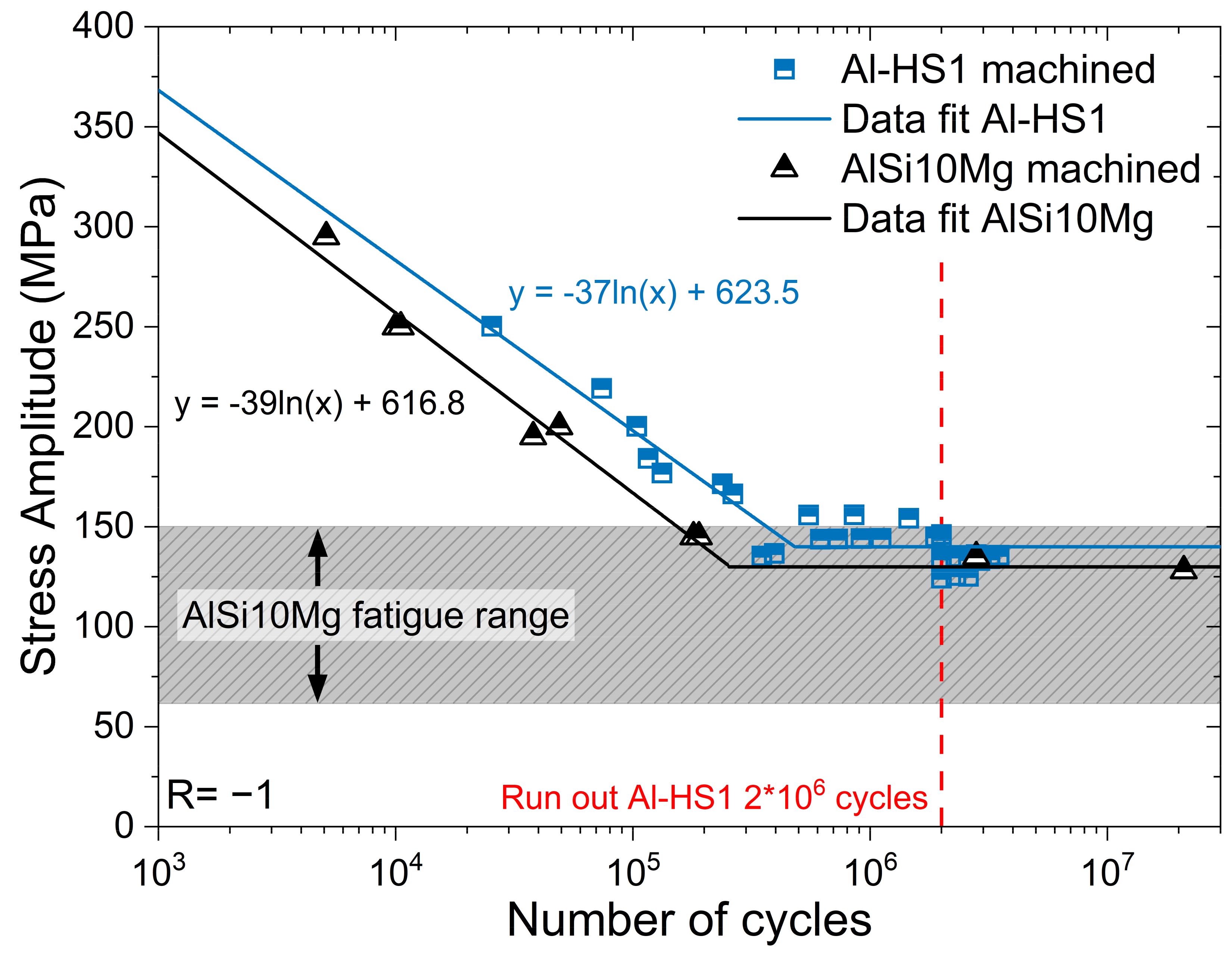
The samples for characterization were prepared by cutting them along the building direction (Z), followed by grinding and polishing, in line with the procedure described in [62]. After polishing, a final step using an OP-S silica suspension was used. All of the samples’ preparations were conducted using a Struers TegraPol 31 machine. Light optical microscopy was conducted using a Zeiss Axioscope 7 microscope, and the stereo optical microscopy was performed using a Zeiss stereo discovery V.20 microscope. Microstructural characterization was conducted on a Zeiss Gemini 450 SEM equipped with a field-emission gun source. The SEM was fitted with an Ultimax energy-dispersive X-ray spectroscopy (EDX) detector from Oxford Instruments, which enables elemental mapping of microstructures at submicron resolutions. A voltage of 5 [kV] and probe current of 1 [nA] were used. For mechanical testing, most of the samples were heat treated to achieve precipitation hardening. A direct aging heat treatment was conducted by introducing the samples in a resistance furnace, with a secondary thermocouple close to the samples to ensure temperatures of ±2 °C. Samples were treated at 375 °C at a heating rate of 10 °C/min, followed by air cooling. The bending fatigue tests were conducted on 30 samples, which were printed along the building direction (Z), heat treated at 375 °C for 8 h. The samples were tested in a four-point bending test rig at Höganäs AB, Sweden. The load ratio was set to fully reversed bending (R = −1.0). The test sequence used the so-called staircase method of evaluation. This method determines the average fatigue strength, i.e., the level at which 50% of the specimens survive until the run-out limit (which was set to 2 × 10⁶ cycles) was reached. In addition to the staircase samples, a few specimens were tested in the low cycle regime. These points suggest reasonable indication of how steep is the Wöhler curve (S–N curve). Furthermore, the runouts were distributed in the X-direction for visibility later. They were all stopped at around 2 × 10⁶ cycles. The final hydraulic manifold was heat treated at 375 °C for 14 h, which represents the peak hardened condition of this material.

3. Microstructure and Mechanical Properties

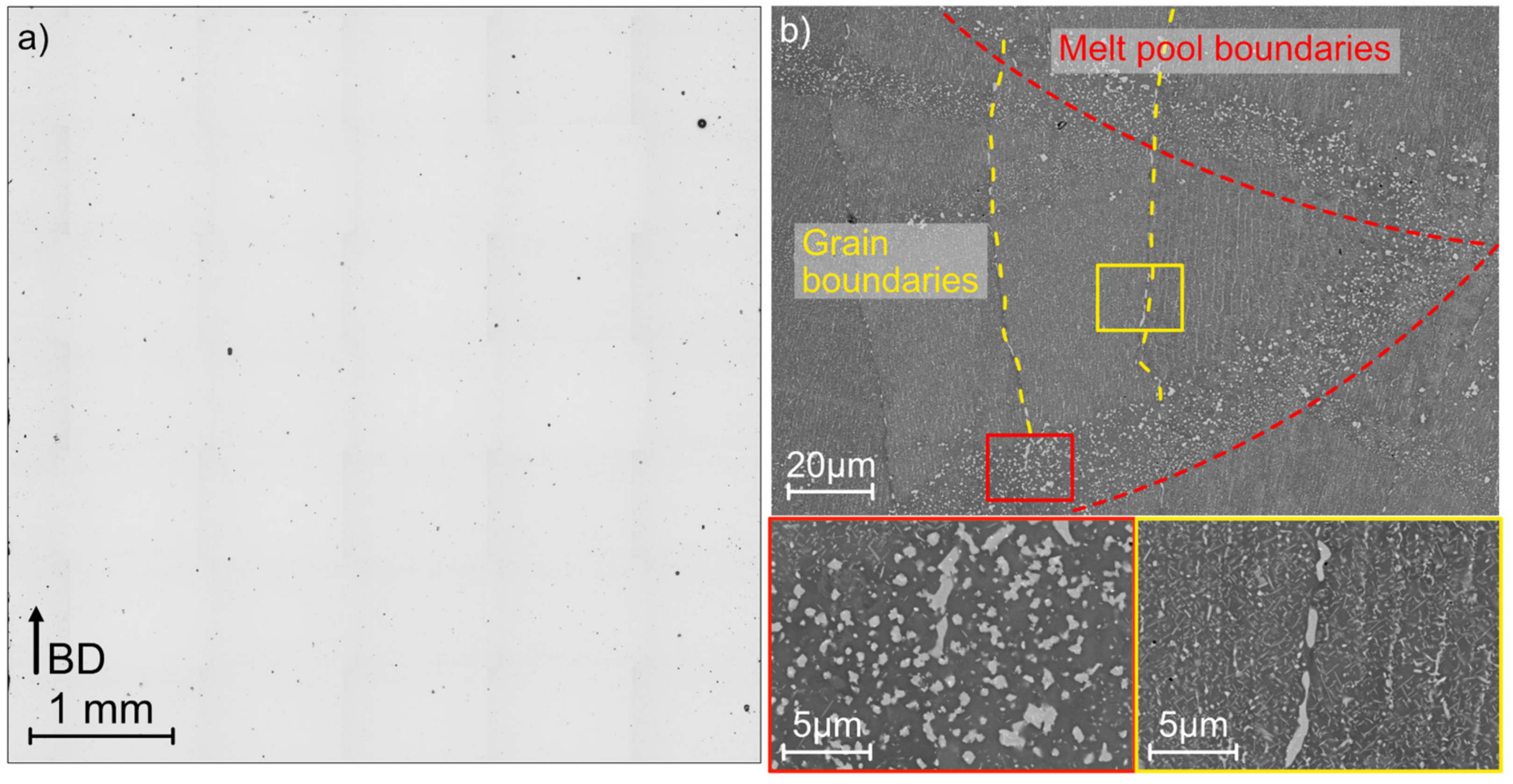
Optical microscopy (OM) conducted on the cube samples cut along the building direction show nominally fully dense samples (see Figure 3). A density of around 99.8% was achieved following the analysis using ImageJ v1.54 software. Each OM-stitched map represented ~100 [mm2] area, with each image taken with a 10× objective lens; thus, each pixel represented a feature of ~1 [µm]. Automatic thresholding was conducted in ImageJ to establish the number of pores. After the OM, the sample was then introduced in an SEM and was shown to possess a fine microstructure overall, with nanometric precipitates rich in Mn, as shown in Figure 4. The primary strengthening contribution comes from even finer L12-type Al3Zr nanoprecipitates (not reported). The sizes of these precipitates were on average <5 [nm] [64,65]. These fine precipitates increased the yield strength from 250 [MPa] in the as-printed condition to ~350 [MPa] in the heat-treated condition (+40% increase).
Relatively coarser precipitates were observed at the grain boundaries and the melt pool boundaries of the material, which could affect the ductility of these precipitation-hardened materials, which has been widely discussed in the literature [66,67,68]. The uniaxial tensile tests, as presented by the authors in [68], are summarized in Table 2. The bending fatigue testing conducted as part of this study resulted in an S–N curve, as shown in Figure 5. Thus, the fatigue strength of the material with a 50% probability was 140.3 [MPa] and with a 90% probability it was 130.7 [MPa]. This seems to be on the higher side of reported values for similar tests conducted on AlSi10Mg material in fatigue tests conducted at R = −1.0 [69,70,71].
The results of the fractography tests conducted on the samples, as shown in Figure 6, reveal that for low cycle fatigue, larger pores are visible (up to 50 [μm]), with a relatively smaller area of fatigue failure. In the case of high cycle fatigue, the damage initiation was seen to be originating from the edge of the sample (point of highest stress in bending loads) and relatively larger area of fatigue failures were observed.

4. Hydraulic Manifold dfAM and Manufacturing

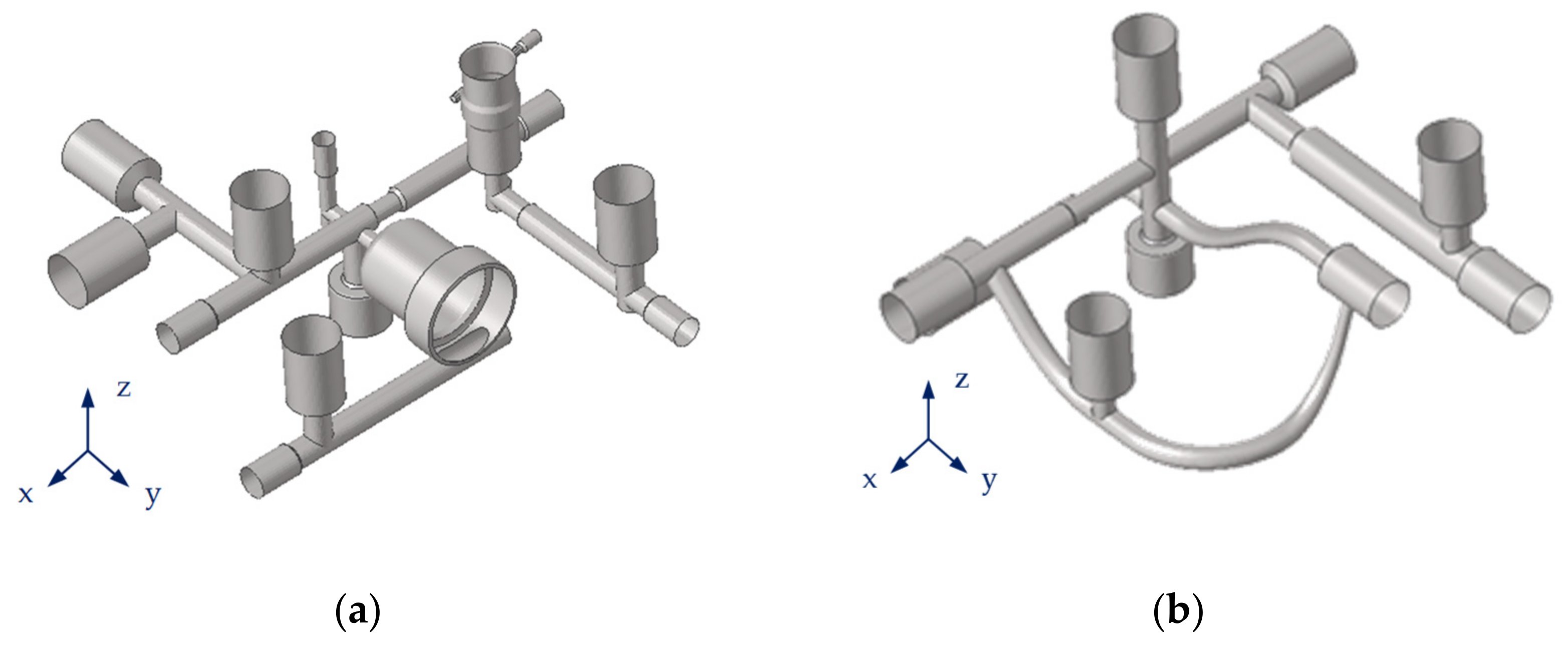
The design for AM of the hydraulic manifold made by AIDRO, Italy, remained unchanged with respect to the former version of AlSi10Mg [57]. The analyzed component was subjected to a re-engineering process aimed at optimizing its former geometry (both internal and external); Figure 7 makes a comparison of the internal ducts. The main drivers of this study were the validation of the performance of the device with the new alloy and the comparison of the experimental results obtained to those with standard AlSi10Mg and conventional CNC machining solutions. Images of the raw test specimen are provided in Figure 8. In the next design iteration, an additional mass reduction is achievable thanks to the improved mechanical properties offered by the new alloy. Instead, the external body of the original sample cannot be reported for confidential reasons. Moreover, from supply chain and manufacturing perspectives, which include 3D printing and postfinishing, the chosen material is particularly promising, because it neither contains expensive rare materials (e.g., Scandium) nor requires intensive postprinting heat treatments, as do some other high-strength Al alloys currently available on the market. Aeronautical flying parts are manufactured for qualified machines, i.e., machined that went through a build process qualification. In general, a change in material for a specific qualified machine is not permitted according to the final requirements of a customer, but in this specific case, a material change from AlSi10Mg and Al-HS1 could not be seen as critical, as it remains within the family of aluminum, with almost the same alloying elements with some % variations in the chemical analysis, without adding other elements (e.g., ceramics) to entail higher mechanical properties. So, a risk of “contamination” from one job to another when switching materials is limited, and in any case a risk mitigation action can be planned, like machine filter replacement procedure. So, the use of this high-strength Al alloy would not represent a blocking point for a parts manufacturer which has qualified processes in AlSi10Mg.The process parameters used to print the parts were the same as AlSi10Mg (standard EOS M290 parameters). As is known, especially when small series are at stake, such as in aeronautics (10 to 50 units per item per year), the cost of the powder is not the main contributor to the final cost of the part. So, even if for commercial strategies the new powder will be sold at higher prices than standard AlSi10Mg, the part price increase is expected to be in the range of 1 to 3%, so not significantly relevant. The final cost of the part might be affected also by nonrecurring costs (e.g., 3D printing process parameters finetuning, coupon testing, definition of adequate heat treatment, NDT, test on demo parts, etc.), but those apply in any aeronautical AM project for the same entity. From a technical point of view, the full viability of the solution here proposed has to be further assessed, taking into account other aspects, like ability to withstand anodization, corrosion behavior, etc. Those points will be the object of future publications.

5. Numerical Analyses and Qualification

5.1. Hydraulic Sizing Conditions

The load conditions used for the analyses and qualification are indicated in Table 3. The static load cases (i.e., proof and burst pressures) refer to the SAE AS8775 [72] specification, while the requirements for the qualification of the fatigue life are specified in SAE ARP1383 Rev. C [73]; the endurance cycles were taken from the hydraulic system’s data, as owned by the aircraft manufacturer and representative of the operative mission profile.

5.2. Finite Element Results

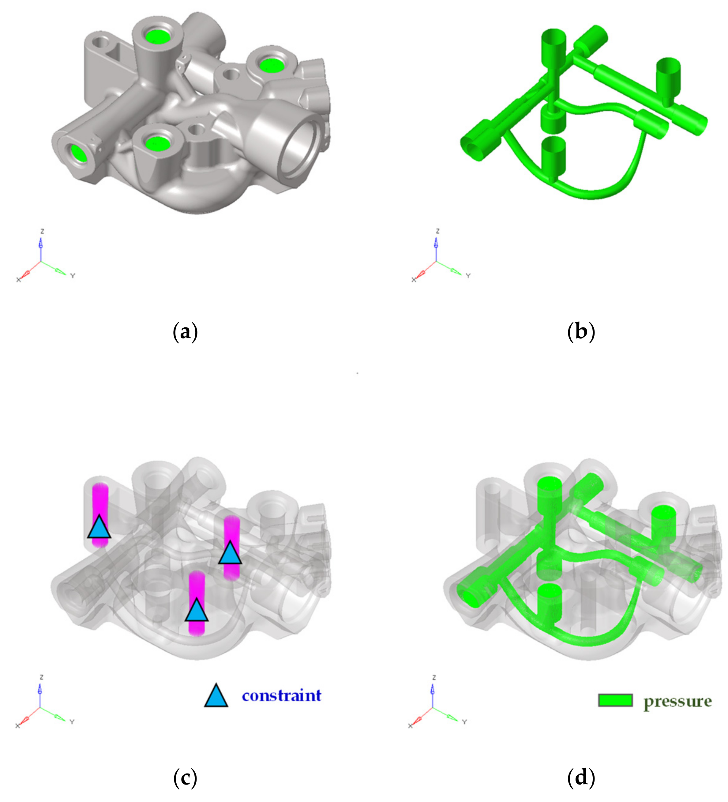
Structural FE analyses were carried out using a 3D FEM model (in Altair Hypermesh environment). The 3D FE model of the manifold body and its internal ducts are detailed in Figure 9a,b. A high density of nodes (around 3.5 M) and elements (solid mesh ctet10 [74], approximately 2.5 M) allowed for the identification of the stress distributions close to that of the crucial design details (i.e., hydraulic pipes and high curvature sections), which is, generally, a potential source of crack initiation.
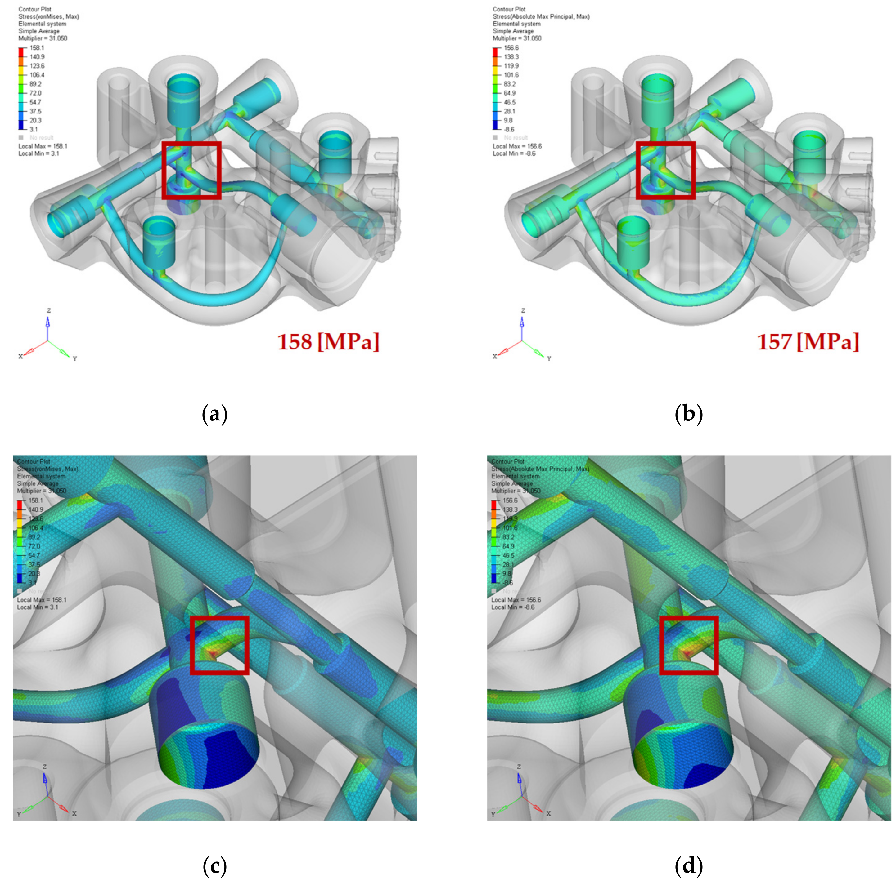
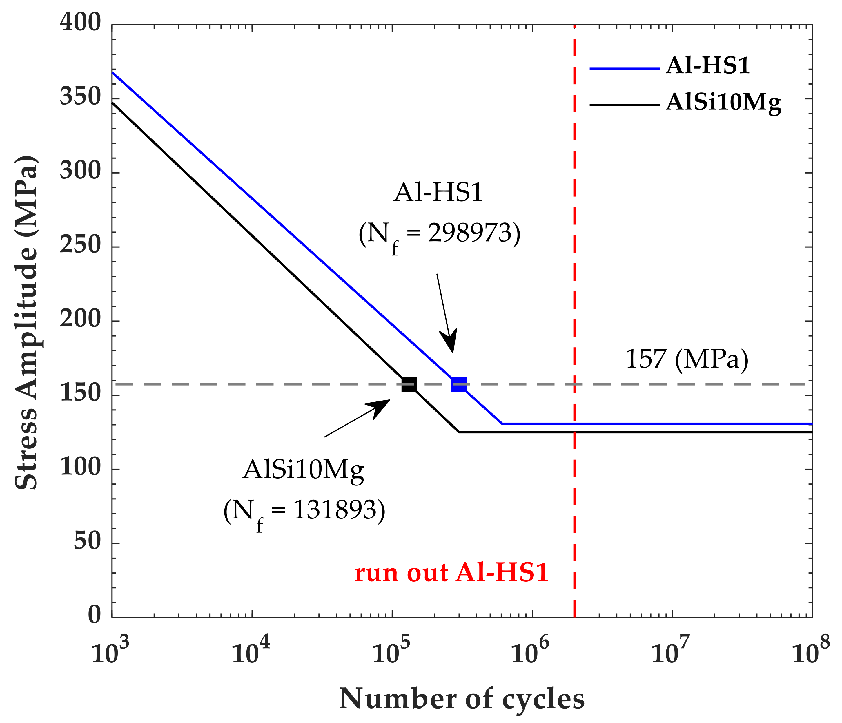
The FE analyses were actually performed considering the hydraulic manifold pinned (tx = ty = tz = 0) at the three interface holes (Figure 9c). The load was a pressure field (pload4 [74]) applied uniformly on the internal wall’s surface (shell elements ctri3 [74], at about 72 k) (Figure 9d). The interesting stress contours are given in Figure 10. The Von Mises stress peak (158 [MPa]) at the limit load occurred at the internal ducts, usually representing the critical areas of these components (Figure 10a,c). The max principal stress map used in the impulse fatigue analysis is provided in Figure 10b, and the pertinent stress peak (157.0 [MPa]) is highlighted in Figure 10d and was used for the extrapolation of the fatigue cycles in Figure 11. The safety margins (MS) at the static and cyclic loads are indicated in Table 4.
The next relationships were used for the static safety margins at the limit (1), ultimate (2) loads, and fatigue damage calculations (3). These resistance criteria were based on a consideration of the structural parts as safe from failure if the MS were above 0.0 while the cumulated damage was less than 1.0.
M S l i m = L i m i t   V o n   M i s e s   s t r e s s Y i e l d   s t r e n g t h 1 = f y f t y 1
M S u l t = U l t i m a t e   V o n   M i s e s   s t r e s s T e n s i l e   s t r e n g t h 1 = f u f t u 1
D = i i t h   c y c l e s   r e q u i r e d c y c l e s   t o   f a i l u r e = i n i N f

5.3. Qualification Tests Overview

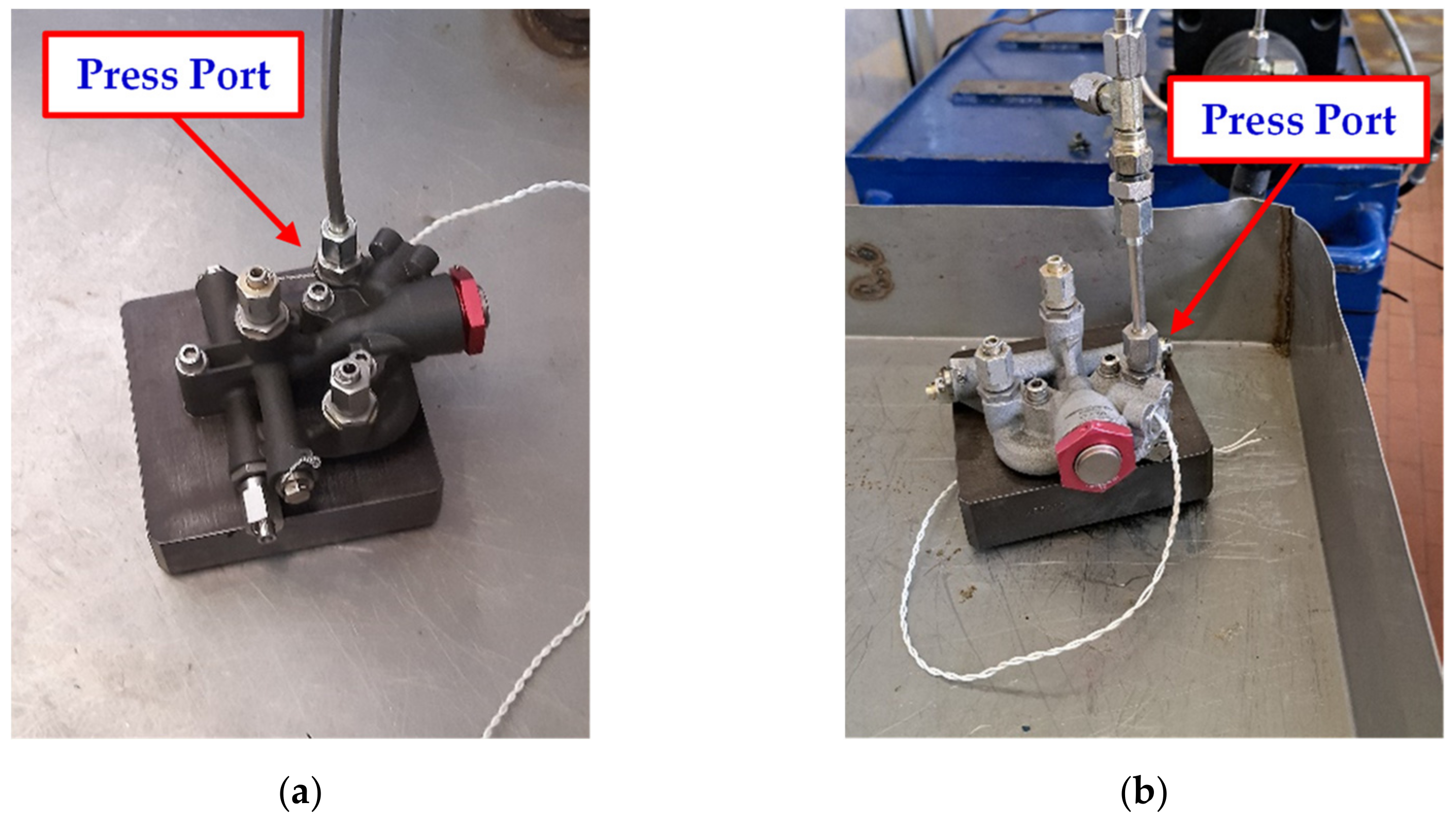
Compliance with the structural and functional requirements, as explained in Table 5, was demonstrated through dedicated bench tests. Figure 12 shows both of the test articles, as follows: the first one (in already-verified AlSi10Mg alloy, Figure 12a) and the one made with the Al-HS1 alloy (Figure 12b). All experimental activities were carried out at the Magnaghi Aeronautica Qualification Laboratory, Naples, Italy.
A proof pressure equal to PP = 1.5 × DOP (DOP: design operative pressure) was applied at the temperature specified at least two successive times and held for 2 min for each pressure application. The rate of the increase in pressure did not exceed 25,000 [psi] per minute. No evidence of external leakage or permanent was allowed. In the case of the burst pressure load (BP = 2.5 × DOP), the component did not rupture; because of its destructive nature, this test was performed last [72]. The component was subjected to cyclic operations (i.e., endurance) and to other fatigue tests, such as hydraulic impulse. For aircraft applications, the endurance profile was based on a duty cycle as per its operative conditions. Because of the usage of the component as an emergency control module, 5,000 cycles were considered adequate to represent the functional loading window. The impulse fatigue pressure levels and test cycles were recommended in SAE ARP1383, [73], as follows: for a fixed-wing aircraft category, utility valves were tested for 100,000 cycles, achieving a max pressure equal to the proof limit. The following were the reference test conditions:
-
Hydraulic fluid conforming to MIL-PRF-5606J (type II) for the supply pressure [75];
-
A hydraulic bench, including a pump source, controlled by the relief pressure valve;
-
Test temperature of about +30 ± 15 °C;
-
A contamination level of the hydraulic fluid of class 7 or better, as per NAS 1638;
-
Hydraulic fluid supplied to the press port, and a pressure value recorded by means of a pressure transducer (Figure 13a). All other ports were closed with actual plugs and hydraulic fittings;
-
Load pressure profiles as plotted in Figure 13b.
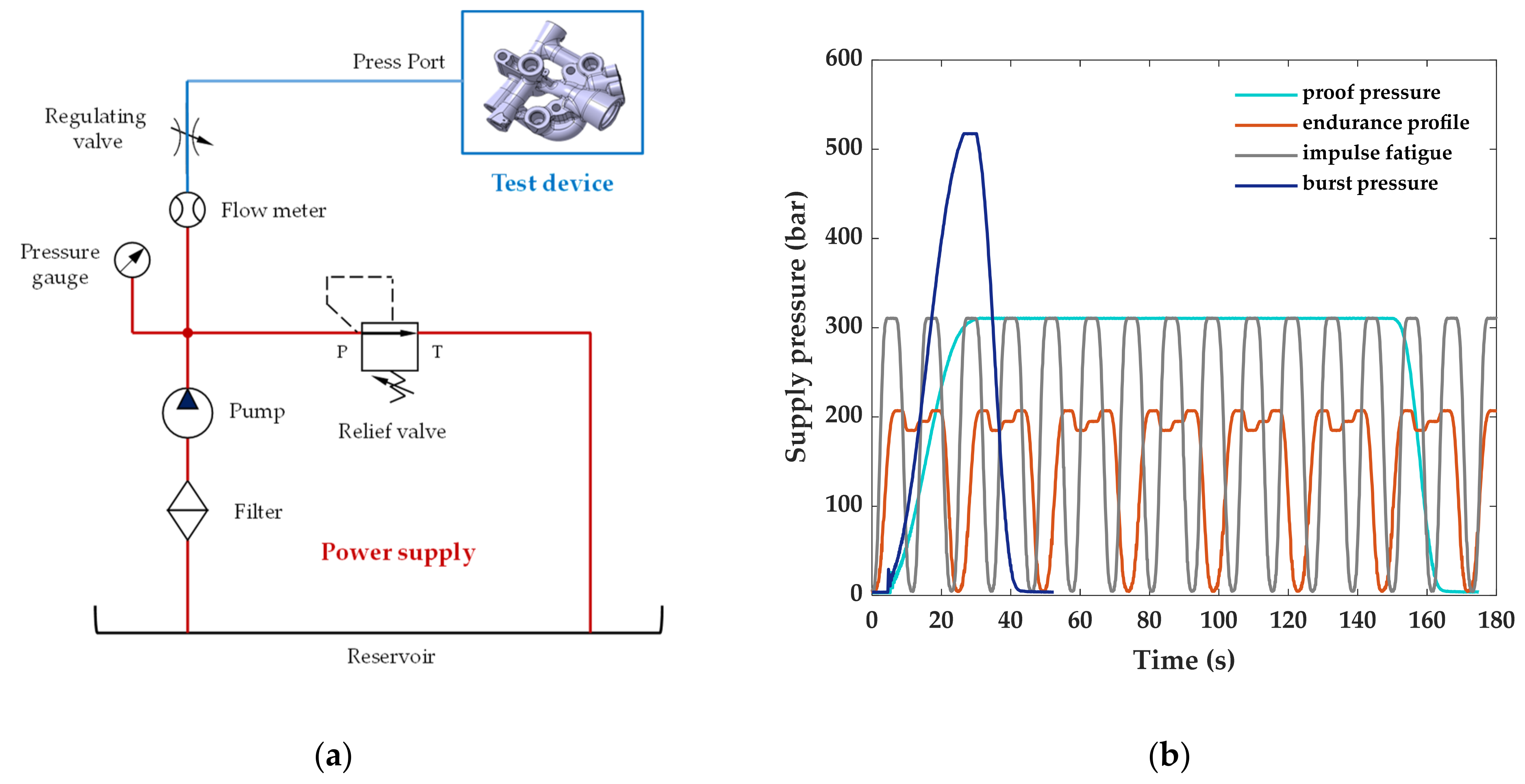
Figure 13. Hydraulic manifold test stand: (a) hydraulic layout; (b) pressure load profiles.
Applsci 14 04647 g013
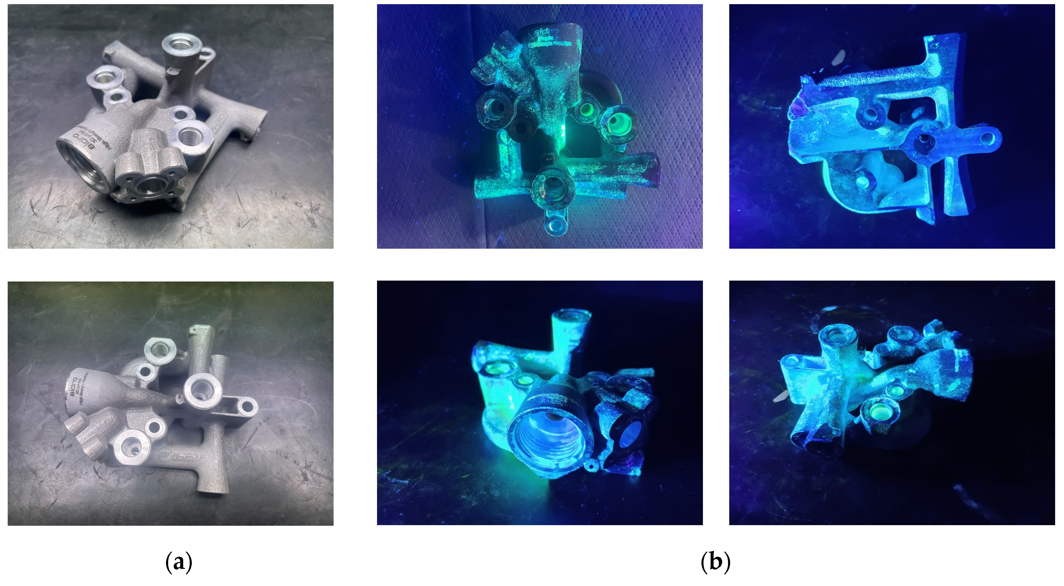
The fulfilment of the structural requirements was proved by a detailed visual inspection addressed to detect any potential cracks or hydraulic oil leakages that occurred. Furthermore, no oil loss and fluid pressure changes were measured in an operational cycle subsequent to the structural test sequences. The test article was then disassembled from any plug and valve in order to submit it to a preliminary nondestructive inspection (NDI) consisting of an immersion cycle of about 30 min in dye penetrating liquids (Figure 14) at the Magnaghi Aeronautica Quality facilities, Naples, Italy. Exposure to UV light then allowed for the verification of the presence of possible surface-breaking defects and wear near the threads (largely stressed by fatigue cycles). Some irregularities detected were mainly associated with the surface porosity and a lack of finishing treatments, which was not foreseen with this prototype, rather than the occurrence of structural flaws.

6. Discussion of the Results

The characteristics of the material examined (Al-HS1) were compared with a widely used Al alloy in order to highlight the benefits, especially regarding the mechanical properties. As mentioned above, the comparison with a standard alloy was motivated only by the facts that it had already been surveyed by the authors and a term of comparison was needed for the present study. It is well recognized that the mechanical properties and chemical formulations are different. This alloy consists of a fine microstructure that derives strength from the secondary precipitation enabled via heat treatments compared to the eutectic Al-Si network in the case of AlSi10Mg. Such a unique microstructure is promising in structural applications, compared to AlSi10Mg (in its machined form), which has a greater allowable yield (about 55.9% in the Z-direction and 36.4% in the XY-plane) and maximum fatigue cycles (+125%); conversely, there was a maximum decrease in the tensile strength of near 8.1%, with a small increase in the mass density (+13.0%). These advantages would allow for the evaluation of its suitability where high structural strength is required and weight constraints need to be met simultaneously. The enhanced structural resilience against the limit load could potentially balance the specific weight increase by utilizing more efficient geometries, where applicable and in line with other relevant design and functional criteria. The good fatigue capacity also makes this alloy attractive in other primary aeronautical equipment of which more operating cycles are expected (such as hydraulic actuators for extension–retraction tasks and shock absorbers). Moreover, the characterized cyclic resistance could suggest an appreciated behavior with respect to the vibrations of aircraft loading profiles. Applications in other engineering sectors (biomedical, naval, railway, and automotive) are certainly worthy of being explored depending on the specific requirements.

7. Conclusions

This work is part of a research path started by the authors and aimed at defining a qualification process for 3D printed components, in particular for aeronautical applications. Production standards are still in an evolving phase, which makes it necessary to establish the key elements required for a certification methodology. A critical point for AM applications in aerospace is to delineate accepted certification rules; repeatable physical characteristics should be ensured so that end-user systems can meet reliability and safety expectations. The certification requirements are mainly mission-based depending on the classification of the failure conditions by the severity of the effect and, therefore, on the class criticality identified for the system itself. Current standards for traditional manufacturing and emerging ones, such as dfAM advances, should complement each other to ensure a common streamlined homologation method. These aspects will be taken into account in the revision of the current qualification standards (i.e., MIL-STD, RTCA-DO and SAE) to include key insights into AM design and testing criteria. Having relied on a design and testing procedure already developed with a first prototypal demonstrator of typical aviation equipment, the authors pursued a case study investigating the use of a novel aluminum alloy tailored for 3D printing. Future outlooks will involve the fine tuning of the material’s characteristics. Corrosion resistance and compatibility with environmental agents are certainly aspects to be explored concerning the final expected use for these kinds of aeronautical devices.

Author Contributions

All authors have been collaborating with each other to obtain a high-quality research output. Conceptualization, B.M., S.B. and L.N.; methodology, M.A. and B.M.; software, M.A., B.M. and P.A.; validation, M.A. and B.M.; formal analysis, M.A. and B.M.; investigation, all; resources, S.B.; data curation, M.A. and B.M.; writing—original draft preparation, M.A. and B.M.; writing—review and editing, M.A., B.M., T.T., M.C. and L.N.; supervision, T.T., M.C. and L.N.; project administration, L.N.; funding acquisition, L.N. All authors have read and agreed to the published version of the manuscript.

Funding

This research was funded by Union’s Horizon 2020 MANUELA (Additive Manufacturing using Metal Pilot Line) project (grant agreement nr. 820774).

Institutional Review Board Statement

Not applicable.

Informed Consent Statement

Not applicable.

Data Availability Statement

Data sharing not applicable.

Acknowledgments

The authors are grateful to the three reviewers for their valuable comments aimed at improving the manuscript. They would like to express a sincere gratitude to all the people from the affiliations involved who contributed within the relevant activities (manufacturing, tests execution, nondestructive controls, etc.) fundamental for the success of the research article.

Conflicts of Interest

Maurizio Arena and Martina Castaldo are employees of Magnaghi Aeronautica of MA Group Company. Tommaso Tirelli and Paolo Ambrogiani are employees of Aidro. Sven Bengtsson is employed by Höganäs AB. The paper reflects the views of the scientists, and not the company. The authors declare no conflict of interest.

References

  1. Dass, A.; Moridi, A. State of the Art in Directed Energy Deposition: From Additive Manufacturing to Materials Design. Coatings 2019, 9, 418. [Google Scholar] [CrossRef]
  2. Liu, R.; Wang, Z.; Sparks, T.; Liou, F.; Newkirk, J. Aerospace applications of laser additive manufacturing. In Laser Additive Manufacturing; Elsevier: Amsterdam, The Netherlands, 2017; pp. 351–371. [Google Scholar]
  3. Selema, A.; Ibrahim, M.N.; Sergeant, P. Metal Additive Manufacturing for Electrical Machines: Technology Review and Latest Advancements. Energies 2022, 15, 1076. [Google Scholar] [CrossRef]
  4. Chatham, C.A.; Long, T.E.; Williams, C.B. A review of the process physics and material screening methods for polymer powder bed fusion additive manufacturing. Prog. Polym. Sci. 2019, 93, 68–95. [Google Scholar] [CrossRef]
  5. Mishra, A.K.; Kumar, A. Computational analysis of the thermo-hydrodynamic transport processes during substrate re-melting in laser powder bed fusion of AlSi10Mg. Therm. Sci. Eng. Prog. 2023, 39, 101698. [Google Scholar] [CrossRef]
  6. Sun, S.; Brandt, M.; Easton, M. 2—Powder bed fusion processes: An overview. Laser Addit. Manuf. 2017, 55–77. [Google Scholar]
  7. Dejene, N.D.; Lemu, H.G. Current Status and Challenges of Powder Bed Fusion-Based Metal Additive Manufacturing: Literature Review. Metals 2023, 13, 424. [Google Scholar] [CrossRef]
  8. Gülcan, O.; Günaydın, K.; Tamer, A. The State of the Art of Material Jetting—A Critical Review. Polymers 2021, 13, 2829. [Google Scholar] [CrossRef]
  9. Li, M.; Du, W.; Elwany, A.; Pei, Z.; Ma, C. Metal Binder Jetting Additive Manufacturing: A Literature Review. J. Manuf. Sci. Eng. 2020, 142, 090801. [Google Scholar] [CrossRef]
  10. Suwanpreecha, C.; Manonukul, A. A Review on Material Extrusion Additive Manufacturing of Metal and How It Compares with Metal Injection Moulding. Metals 2022, 12, 429. [Google Scholar] [CrossRef]
  11. Riccio, C.; Civera, M.; Ruiz, O.G.; Pedullà, P.; Reinoso, M.R.; Tommasi, G.; Vollaro, M.; Burgio, V.; Surace, C. Effects of Curing on Photosensitive Resins in SLA Additive Manufacturing. Appl. Mech. 2021, 2, 942–955. [Google Scholar] [CrossRef]
  12. Gibson, I.; Rosen, D.; Stucker, B.; Khorasani, M. Sheet Lamination. In Additive Manufacturing Technologies; Springer International Publishing: Cham, Switzerland, 2021; pp. 253–283. [Google Scholar]
  13. Tan, L.J.; Zhu, W.; Zhou, K. Recent progress on polymer materials for additive manufacturing. Adv. Funct. Mater. 2020, 30, 2003062. [Google Scholar] [CrossRef]
  14. Jadhav, A.; Jadhav, V.S. A review on 3D printing: An additive manufacturing technology. Mater. Today Proc. 2022, 62, 2094–2099. [Google Scholar] [CrossRef]
  15. Praveena, B.A.; Lokesh, N.; Buradi, A.; Santhosh, N.; Praveena, B.L.; Vignesh, R. A comprehensive review of emerging additive manufacturing (3D printing technology): Methods, materials, applications, challenges, trends and future potential. Mater. Today Proc. 2022, 52, 1309–1313. [Google Scholar]
  16. Srinivasan, K.V.; Manimaran, A.; Arulprakasajothi, M.; Devante, M.; Arolkar, V.A. Design and development of porous regenerator for Stirling cryocooler using additive manufacturing. Therm. Sci. Eng. Prog. 2019, 11, 195–203. [Google Scholar] [CrossRef]
  17. McDonough, J.R. A perspective on the current and future roles of additive manufacturing in process engineering, with an emphasis on heat transfer. Therm. Sci. Eng. Prog. 2020, 19, 100594. [Google Scholar] [CrossRef]
  18. Favero, G.; Bonesso, M.; Rebesan, P.; Dima, R.; Pepato, A.; Mancin, S. Additive manufacturing for thermal management applications: From experimental results to numerical modeling. Int. J. Thermofluids 2021, 10, 100091. [Google Scholar] [CrossRef]
  19. Mollamahmutoglu, M.; Yilmaz, O. Volumetric heat source model for laser-based powder bed fusion process in additive manufacturing. Therm. Sci. Eng. Prog. 2021, 25, 101021. [Google Scholar] [CrossRef]
  20. Tucker, R.; Khatamifar, M.; Lin, W.; McDonald, K. Experimental investigation of orientation and geometry effect on additive manufactured aluminium LED heat sinks under natural convection. Therm. Sci. Eng. Prog. 2021, 23, 100918. [Google Scholar] [CrossRef]
  21. Froes, F.; Boyer, R.; Dutta, B. Introduction to Aerospace Materials Requirements and the Role of Additive Manufacturing; Elsevier Inc.: Amsterdam, The Netherlands, 2019. [Google Scholar]
  22. European Commission. European Aeronautics: A Vision for 2020; European Communities: Luxembourg, 2001. [Google Scholar]
  23. European Commission. Flightpath 2050; EU: Luxembourg, 2011. [Google Scholar]
  24. ISO/ASTM 52920:2023; Additive Manufacturing—Qualification Principles—Requirements for Industrial Additive Manufacturing Processes and Production Sites. International Organization for Standardization: Geneva, Switzerland, 2023.
  25. DNV-ST-B203; Additive Manufacturing of Metallic Parts, Edition 2022-10. Greater: Oslo, Norway, 2022.
  26. Blakey-Milner, B.; Gradl, P.; Snedden, G.; Brooks, M.; Pitot, J.; Lopez, E.; Leary, M.; Berto, F.; du Plessis, A. Metal additive manufacturing in aerospace: A review. Mater. Des. 2021, 209, 110008. [Google Scholar] [CrossRef]
  27. Alami, A.H.; Olabi, A.G.; Alashkar, A.; Alasad, S.; Aljaghoub, H.; Rezk, H.; Abdelkareem, M.A. Additive manufacturing in the aerospace and automotive industries: Recent trends and role in achieving sustainable development goals. Ain Shams Eng. J. 2023, 14, 102516. [Google Scholar] [CrossRef]
  28. Zhang, X.; Liang, E. Metal additive manufacturing in aircraft: Current application, opportunities and challenges. IOP Conf. Ser. Mater. Sci. Eng. 2019, 493, 012032. [Google Scholar] [CrossRef]
  29. Titanium, N. Norsk Titanium to Deliver the World’s First FAA-Approved, 3DPrinted, Structural Titanium Components to Boeing|Additive Manufacturing (AM). Available online: https://additivemanufacturing.com/2017/04/10/norsk-titanium-to-deliver-the-worlds-first-faa-approved-3d-printed-structural-titanium-components-to-boeing/ (accessed on 4 January 2024).
  30. Lyons, B. Additive Manufacturing in Aerospace: Examples and Research Outlook, The Boeing Company, Frontiers of Engineering: Reports on Leading-Edge Engineering from the 2011 Symposium; National Academies Press: Washington, DC, USA, 2012. [Google Scholar]
  31. Boeing, S.A. Acess Door Latch. Available online: https://www.additivemanufacturing.media/articles/what-is-the-role-for-additive-manufacturing-in-aircraft-structural-components (accessed on 2 January 2024).
  32. Gerald, M.; Cross Robert, R. Filler, Additive Manufacturing (AM) of a Rotorcraft Gearbox Housing Independent Research & Development (IRAD) Project, Boeing Research and Technology; The Boeing Company: Arlington County, VA, USA, 2019. [Google Scholar]
  33. Romero, I.; Martin, J.M.; Marzal, M.; Gallego, J.; Calero, M.A.; Martin, J.C. Additive Manufacturing (AM). Status in Airbus Defence and Space (Spain). In Proceedings of the 8th European Conference for Aeronautics and Space Sciences (EUCASS), Madrid, Spain, 1–4 July 2019. [Google Scholar]
  34. Kumar, L.J.; Nair, C.G.K. Current trends of additive manufacturing in the aerospace industry. In Advances in 3D Printing & Additive Manufacturing Technologies; Springer Singapore: Singapore, 2017; pp. 39–54. [Google Scholar]
  35. Orme, M.E.; Gschweitl, M.; Ferrari, M.; Madera, I.; Mouriaux, F. Designing for additive manufacturing: Lightweighting through topology optimization enables lunar spacecraft. J. Mech. Des. Trans. ASME 2017, 139, 100905. [Google Scholar] [CrossRef]
  36. Caujolle, M. First Titanium 3D-Printed Part Installed into Serial Production Aircraft. 2017. Available online: https://www.airbus.com/en/newsroom/press-releases/2017-09-first-titanium-3d-printed-part-installed-into-serial-production (accessed on 2 January 2024).
  37. Tomlin, M.; Meyer, J. Topology optimization of an additive layer manufactured (ALM) aerospace part. In Proceedings of the 7th Altair CAE Technology Conference 2011, Gaydon, UK, 7–9 November 2011; pp. 1–9. [Google Scholar]
  38. Meng, L.; Zhang, W.; Quan, D.; Shi, G.; Tang, L.; Hou, Y.; Breitkopf, P.; Zhu, J.; Gao, T. From topology optimization design to additive manufacturing: Today’s success and tomorrow’s roadmap. Arch. Comput. Methods Eng. 2020, 27, 805–830. [Google Scholar] [CrossRef]
  39. Uhlmann, E.; Kersting, R.; Borsoi Klein, T.; Cruz, M.F.; Borille, A.V. Additive manufacturing of titanium alloy for aircraft components. In Proceedings of the 15th Machining Innovations Conference for Aerospace Industry, Hannover, Germany, 18–19 November 2015; Volume 35, pp. 55–60. [Google Scholar]
  40. General Electric— Additive, LEAP Engine Fuel Nozzle. Available online: https://www.geaerospace.com/news/articles/manufacturing/manufacturing-milestone-30000-additive-fuel-nozzles (accessed on 2 January 2024).
  41. General Electric—Additive, GE9X Engine Additive Parts. Available online: https://www.ge.com/additive/sites/default/files/2020-08/GE9X-Additive-Parts.pdf (accessed on 2 January 2024).
  42. Hoffmann, M.; Elwany, A. In-Space Additive Manufacturing: A Review. J. Manuf. Sci. Eng. 2023, 145, 020801. [Google Scholar] [CrossRef]
  43. Gradl, P.R.; Mireles, O.; Protz, C.S.; Garcia, C. Metal Additive Manufacturing for Propulsion Applications. In AIAA Progress in Astronautics and Aeronautics Book Series; American Institute of Aeronautics and Astronautics, Inc.: Reston, VA, USA, 2022. [Google Scholar]
  44. Gradl, P.R.; Protz, C.S. Technology advancements for channel wall nozzle manufacturing in liquid rocket engines. Acta Astronaut. 2020, 174, 148–158. [Google Scholar] [CrossRef]
  45. Kerstens, F.; Cervone, A.; Gradl, P. End to end process evaluation for additively manufactured liquid rocket engine thrust chambers. Acta Astronaut. 2021, 182, 454–465. [Google Scholar] [CrossRef]
  46. Thales Alenia Space and 3D Systems, Antenna Bracket. Available online: https://www.3dsystems.com/learning-center/case-studies/tipping-point (accessed on 2 January 2024).
  47. Clark, S. Astronauts Fly with SpaceX in Landmark Launch for Commercial Spaceflight. Available online: https://spaceflightnow.com/2020/11/16/astronauts-ride-spacex-crew-capsule-in-landmark-launch-for-commercial-spaceflight/ (accessed on 2 January 2024).
  48. Frazier, W.E. Metal Additive Manufacturing: A Review. J. Mater. Eng. Perform. 2014, 23, 1917–1928. [Google Scholar] [CrossRef]
  49. Haghdadi, N.; Laleh, M.; Moyle, M.; Primig, S. Additive manufacturing of steels: A review of achievements and challenges. J. Mater. Sci. 2021, 56, 64–107. [Google Scholar] [CrossRef]
  50. Armstrong, M.; Mehrabi, H.; Naveed, N. An overview of modern metal additive manufacturing technology. J. Manuf. Process. 2022, 84, 1001–1029. [Google Scholar] [CrossRef]
  51. Narasimharaju, S.R.; Zeng, W.; See, T.L.; Zhu, Z.; Scott, P.; Jiang, X.; Lou, S. A comprehensive review on laser powder bed fusion of steels: Processing, microstructure, defects and control methods, mechanical properties, current challenges and future trends. J. Manuf. Process. 2022, 75, 375–414. [Google Scholar] [CrossRef]
  52. Tshephe, T.S.; Akinwamide, S.O.; Olevsky, E.; Olubambi, P.A. Additive manufacturing of titanium-based alloys—A review of methods, properties, challenges, and prospects. Heliyon 2022, 8, e09041. [Google Scholar] [CrossRef] [PubMed]
  53. Williams, J.C.; Boyer, R.R. Opportunities and issues in the application of titanium alloys for aerospace components. Metals 2020, 10, 705. [Google Scholar] [CrossRef]
  54. Mostafaei, A.; Ghiaasiaan, R.; Ho, I.-T.; Strayer, S.; Chang, K.-C.; Shamsaei, N.; Shao, S.; Paul, S.; Yeh, A.-C.; Tin, S.; et al. Additive manufacturing of nickel-based superalloys: A state-of-the-art review on process-structure-defect-property relationship. Prog. Mater. Sci. 2023, 136, 101108. [Google Scholar] [CrossRef]
  55. Höganäs, A.B. forAM(r) Al-HS1 Powder. Available online: https://www.hoganas.com/en/powder-technologies/products/foram/foram-al-hs1-20-63-ga/ (accessed on 4 January 2024).
  56. Mehta, B. Development of High Performance Aluminium Alloys Tailored for Powder Bed Fusion-Laser Beam. Ph.D. Thesis, Chalmers University of Technology, Gothenburg, Sweden, 2023. [Google Scholar]
  57. Arena, M.; Ambrogiani, P.; Raiola, V.; Bocchetto, F.; Tirelli, T.; Castaldo, M. Design and Qualification of an Additively Manufactured Manifold for Aircraft Landing Gears Applications. Aerospace 2023, 10, 69. [Google Scholar] [CrossRef]
  58. Biedermann, M.; Beutler, P.; Meboldt, M. Automated design of additive manufactured flow components with consideration of overhang constraint. Addit. Manuf. 2021, 46, 102119. [Google Scholar] [CrossRef]
  59. Diegel, O.; Schutte, J.; Ferreira, A.; Chan, Y.L. Design for additive manufacturing process for a lightweight hydraulic manifold. Addit. Manuf. 2020, 36, 101446. [Google Scholar] [CrossRef]
  60. Alshare, A.A.; Calzone, F.; Muzzupappa, M. Hydraulic manifold design via additive manufacturing optimized with CFD and fluid-structure interaction simulations. Rapid Prototyp. J. 2019, 25, 1516–1524. [Google Scholar] [CrossRef]
  61. Krailling/Munich, Germany. Available online: https://www.eos.info (accessed on 4 January 2024).
  62. Mehta, B.; Nyborg, L.; Frisk, K.; Hryha, E. Al–Mn–Cr–Zr-based alloys tailored for powder bed fusion-laser beam process: Alloy design, printability, resulting microstructure and alloy properties. J. Mater. Res. 2022, 3, 1–13. [Google Scholar] [CrossRef]
  63. Mehta, B.; Frisk, K.; Nyborg, L. Advancing Novel Al-Mn-Cr-Zr Based Family of Alloys Tailored for Powder Bed Fusion-Laser Beam Process. J. Alloys Compd. 2023, 967, 171685. [Google Scholar] [CrossRef]
  64. Mehta, B.; Frisk, K.; Nyborg, L. Effect of Precipitation Kinetics on Microstructure and Properties of Novel Al-Mn-Cr-Zr Based Alloys Developed for Powder Bed Fusion—Laser Beam Process. J. Alloys Compd. 2022, 920, 165870. [Google Scholar] [CrossRef]
  65. Knipling, K.E.; Dunand, D.C.; Seidman, D.N. Precipitation evolution in Al-Zr Al-Zr-Ti alloys during aging at 450–600 °C. Acta Mater. 2008, 56, 1182–1195. [Google Scholar] [CrossRef]
  66. Kaufman, J.G. Properties and Applications of Wrought Aluminum Alloys. Prop. Sel. Alum. Alloy 2019, 2, 202–275. [Google Scholar]
  67. Mackenzie, D.S. Metallurgy of Heat Treatable Aluminum Alloys; ASM International: Novelty, OH, USA, 2016; Volume 4. [Google Scholar]
  68. Bengtsson, S.; Mehta, B.; Frisk, K.; Nyborg, L. New Aluminium Alloy Tailored for Powder Bed Fusion—Laser Beam Process. In Proceedings of the WorldPM 2022 Congress & Exhibition: Conference Proceedings, Lyon, France, 9–13 October 2022. [Google Scholar]
  69. Uzan, N.E.; Shneck, R.; Yeheskel, O.; Frage, N. Fatigue of AlSi10Mg specimens fabricated by additive manufacturing selective laser melting (AM-SLM). Mater. Sci. Eng. A 2017, 704, 229–237. [Google Scholar] [CrossRef]
  70. Mower, T.M.; Long, M.J. Mechanical behavior of additive manufactured, powder-bed laser-fused materials. Mater. Sci. Eng. A 2016, 651, 198–213. [Google Scholar] [CrossRef]
  71. Raja, A.; Cheethirala, S.R.; Gupta, P.; Vasa, N.J.; Jayaganthan, R. A review on the fatigue behaviour of AlSi10Mg alloy fabricated using laser powder bed fusion tech-nique. J. Mater. Res. Technol. 2022, 17, 1013–1029. [Google Scholar] [CrossRef]
  72. SAE-AS8775; Military Specification: Hydraulic System Components, Aircraft and Missiles, General Specification for AS8775. SAE International: Warrendale, PA, USA, 1998.
  73. SAE ARP1383; Aerospace—Impulse Testing of Hydraulic Components, rev. C. SAE International: Warrendale, PA, USA, 2013.
  74. MSC Nastran®. Quick Reference Guide 2021; MSC Software: Newport Beach, CA, USA, 2021. [Google Scholar]
  75. MIL-PRF-5606J; Performance Specification: Hydraulic Fluid, Petroleum Base; Aircraft, Missile, and Ordnance. U.S. Department of Defense Military Specifications and Standards: Arlington County, VA, USA, 2018.
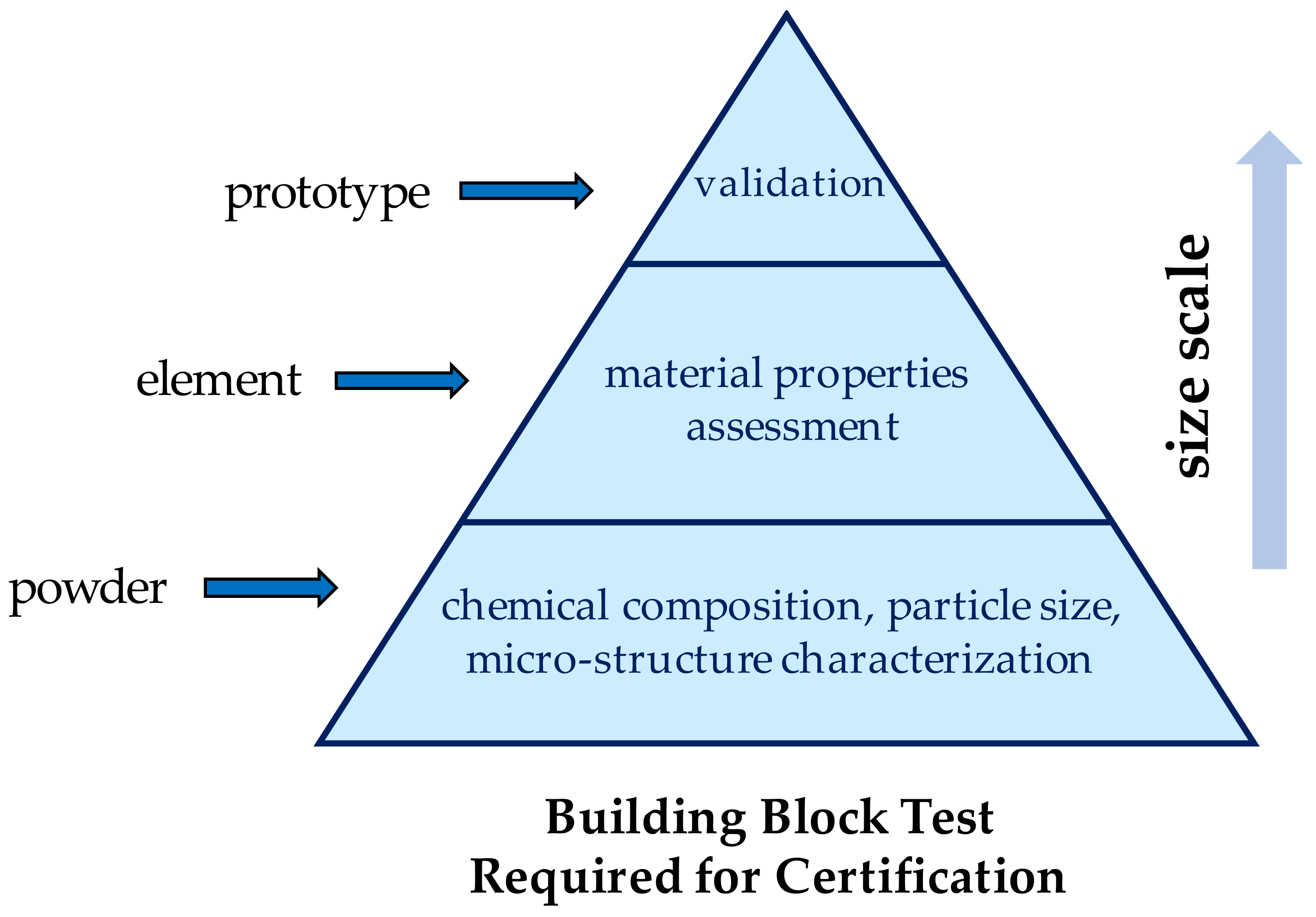
Figure 1. AM building blocks: the main steps toward the certification of parts.
Applsci 14 04647 g001
Figure 2. Engineering end-to-end process addressed for Al-HS1 qualification.
Applsci 14 04647 g002
Figure 3. Bending fatigue sample after machining: (a) dog bone sample geometry; (b) test setup for the four-point bending test.
Applsci 14 04647 g003
Figure 4. (a) Optical microscopic image of a sample along the building direction (BD); (b) SEM images showing the microstructure with insets focusing on precipitates at melt pool boundaries (red) and grain boundaries (yellow) respectively.
Applsci 14 04647 g004
Figure 5. Bending fatigue data at R = −1.0 for the Al-HS1 printed along the building direction. Run-out samples (at 2 × 10⁶ cycles) are spread along the X-axis for the visualization. The fatigue strength range is as reported for AlSi10Mg in the literature [69].
Applsci 14 04647 g005
Figure 6. Fractography tests on Al-HS1 after the bending fatigue tests: (a) low cycle fatigue sample; (b) high cycle fatigue sample.
Applsci 14 04647 g006
Figure 7. Details of the hydraulic manifold channels: (a) former geometry; (b) after the optimization.
Applsci 14 04647 g007
Figure 8. Manifold after printing: (a) before drilling; manifold after machining and postprocessing heat treatment; (b) thread detail (top); (c) plugs threads detail (front).
Applsci 14 04647 g008
Figure 9. Details of the three-dimensional FE model: (a) 3D model; (b) inner walls; (c) constraints; (d) internal pressure.
Applsci 14 04647 g009
Figure 10. Stress maps (limit pressure load, PP = 31.05 [MPa]): (a) Von Mises; (b) max principal; (c) Von Mises peak (inner flow channels); (d) max principal peak (inner flow channels).
Applsci 14 04647 g010
Figure 11. Fatigue life calculations of the manifold at a pulsating pressure for the Al-HS1 and AlSi10Mg alloys.
Applsci 14 04647 g011
Figure 12. Hydraulic manifold test articles: (a) AlSi10Mg [57]; (b) Al-HS1 type.
Applsci 14 04647 g012
Figure 14. NDI of the hydraulic manifold: (a) disassembled test article; (b) UV images.
Applsci 14 04647 g014
Table 1. Chemical compositions of the materials used in this study [62,63]. All compositions are in wt%. Fe and Si are considered impurities from the atomization process.
AlloyChemical Composition
Al-HS1Al 5 Mn 0.8 Cr 0.6 Zr 0.17 Fe 0.24 Si
AlSi10MgAl 9.8 Si 0.33 Mg 0.15 Fe
Table 2. Summary of the tensile properties of Al-HS1 reported previously [68] and compared to AlSi10Mg [69]. All samples of Al-HS1 were tested in a heat-treated state (375 °C 14 h) and the AlSi10Mg in the as-printed state.
AlloyDirectionYield Strength, ftyTensile Strength, ftuElongation to FailureDensity
(Z), (XY)[MPa][MPa][%][g/cm3]
Al-HS1Vertical (Z)3434304.82.99
Horizontal (XY)35644110.4
AlSi10MgVertical (Z)22046810.72.645
Horizontal (XY)26144915.7
Table 3. Hydraulic loading conditions.
TestPressureNo. of CyclesReference
[bar][-][-]
0. Supply PressureDOP = 207--
1. Proof Pressure1.5 × DOP = 310.5-SAE AS8775 [72]
2. Endurance Cycles5–207–185–195–207–55,000Legacy spectrum
3. Hydraulic Fatigue0.5–310.5–0.5100,000SAE ARP1383 Rev. C [73]
4. Burst Pressure2.5 × DOP = 517.5-SAE AS8775 [72]
Table 4. Margins of safety for the static and fatigue loads.
Load CaseDescriptionSafety Margin/Fatigue Damage
Proof pressureStatic load
(limit)
AlSi10Mg: MSlim = (220/158) − 1 = 0.39
Al-HS1: MSlim = (343/158) − 1 = high
Burst pressureStatic load
(ultimate)
AlSi10Mg: MSult = (449/263) − 1 = 0.71
Al-HS1: MSult = (430/263) − 1 = 0.63
Pulsating cyclesFatigueAlSi10Mg: D = 100,000/131,893 = 0.76 < 1.0
Al-HS1: D = 100,000/298,973 = 0.33 < 1.0
MS > 1.0 is denoted with “high”.
Table 5. Test matrix and pass/fail criteria.
Load CaseDescriptionSuccess/Failure Criteria
Proof pressureStatic (2 min)No permanent deformation, pressure drop, and external leakage
EnduranceCyclicNo leakage or evidence of excessive wear or malfunctioning
Pulsating cyclesCyclicNo failure or permanent deformation
Burst pressureStatic (3 s)No rupture, pressure drop, or external leakage
Disclaimer/Publisher’s Note: The statements, opinions and data contained in all publications are solely those of the individual author(s) and contributor(s) and not of MDPI and/or the editor(s). MDPI and/or the editor(s) disclaim responsibility for any injury to people or property resulting from any ideas, methods, instructions or products referred to in the content.