Article

Seismic Response Analysis of Underground Large Liquefied Natural Gas Tanks Considering the Fluid–Structure–Soil Interaction

1
Department of Geotechnical Engineering, Tongji University, Shanghai 200092, China
2
China Shipbuilding NDRI Engineering Co., Ltd., Shanghai 200090, China
3
CNOOC Gas and Power Group Co., Ltd., Beijing 100028, China
*
Author to whom correspondence should be addressed.
Appl. Sci. 2024, 14(11), 4753; https://doi.org/10.3390/app14114753
Submission received: 10 April 2024 / Revised: 25 May 2024 / Accepted: 28 May 2024 / Published: 31 May 2024
(This article belongs to the Section Civil Engineering)

Abstract

:
The seismic response of underground liquefied natural gas (LNG) storage tanks has been a significant focus in both academic and engineering circles. This study utilized Ansys (2021R1) to conduct seismic analyses of large-capacity LNG tanks, considering the fluid–structure–soil coupling interaction (FSSI), and it was solved using the Volume of Fluid model (VOF) and Finite Element Method (FEM). The mechanical properties of both the LNG tank structure and soil were simulated using solid elements, and seismic acceleration loads were applied. An analysis of liquefied natural gas was performed using fluid elements within FLUENT. Initially, a modal analysis of the tank was conducted, which revealed lower frequencies for a full-liquid tank (3.193 Hz) compared to an empty tank (3.714 Hz). Subsequently, the seismic responses of both the aboveground and underground LNG tank structures were separately simulated, comparing the acceleration, stress, and displacement of the tank wall structures. The findings indicate that the peak relative displacement of the aboveground empty tank wall is 122 mm, less than that of a full tank (136 mm), while the opposite holds true for underground tanks. The period and wave height of LNG liquid shaking in underground tanks are lower than those in aboveground tanks, which is more conducive to tank safety. The deformation and acceleration of underground tanks are lower than those of aboveground tanks, but the Mises stress is higher. The results indicate that underground LNG tank structures are safer under earthquake conditions.

1. Introduction

Liquefied natural gas (LNG), renowned for its ability to only cause low levels of pollution, as well as its cleanliness, safety, and efficiency, stands as a widely embraced energy source across the globe [1]. Among the prevalent categories of large LNG storage tanks are aboveground vertical tanks, semi-buried tanks, and fully buried underground tanks [1]. Due to their comparatively thin walls, aboveground tanks are susceptible to damage during seismic events. Earthquakes not only jeopardize the costly tank structure but also amplify the severity of secondary disasters such as fires and environmental contamination stemming from LNG leakage. The vulnerabilities of vertical tanks during past seismic incidents have resulted in instances of bottom uplift, wall buckling, liquid spillage, dome rupture, pipeline failure, and foundational damage [2,3]. In contrast, fully buried underground tanks, lauded for their robust seismic resistance and enhanced safety, have found extensive applications in nations like Japan and South Korea.
The research on liquid storage tanks encompasses seismic damage surveys, theoretical explorations, numerical simulation studies, and experimental investigations [4]. In the 1930s, seismic studies on vertical storage tanks, primarily those rigidly anchored to the base, commenced. Acknowledging the complexity of this issue and the technological constraints of the era, Housner developed a classic theoretical model [5] based on previous research. Housner assumed that the tank’s internal liquid was an ideal, incompressible, and non-viscous fluid, while the tank walls were regarded as rigid. The seismic impact of the liquid on the rigid walls was simulated using a mass–spring system to represent the impulsive and convective pressures induced by earthquakes. Veletsos [6] further simplified the tank as a cantilever beam structure with one end fixed, calculating elastic tank pulse pressures under horizontal seismic forces using the assumed mode method. Haroun [7] integrated the theories of Housner and Veletsos, formulating the three-mass-point flexible wall model (Haroun–Housner model), incorporating the convective and pulsating pressures of the liquid. In 2000, Malhotra et al. [8] proposed practical theoretical calculations for tanks with flexible steel or concrete walls. Sun Jiangang [9] and Zheng Jianhua et al. [10], who considered the foundation soil to be a system of translational and rotational spring-damping elements, established a simplified equivalent mechanical model to study whether the seismic response of tank structures was influenced by the elastic properties of the foundation soil. However, these methods either neglected the role of the foundation soil or oversimplified it as a spring-damping element, leading to imprecise results.
Through the proliferation and optimization of numerical methods such as finite element analysis and finite difference methods, scholars have effectively employed numerical software (e.g., Abaqus, Ansys, etc.) to simulate the combined effects of fluid–structure–soil systems. Currently, the most prevalent multi-material fluid–solid coupling algorithms include the Euler method, the Langrange method, the Arbitrary Lagrangian–Eulerian (ALE) method, the Volume of Fluid (VOF) method, and the Coupled Eulerian–Lagrangian (CEL) method. Ibrahim [11] extensively investigated the oscillations of liquid within tanks under seismic loads. The study of the free and forced oscillations of an elastically rotating shell partially filled with an ideal incompressible fluid has also been explored. Sierikvoa [12] utilized Ansys to analyze the response patterns of steel tanks containing nanocomposite materials under seismic conditions. N. Farasat et al. [1] compared the displacements and stresses of aboveground water tanks and underground tanks under seismic loads, revealing that underground tanks have fewer displacements and stresses, indicating their relative safety. Lyvavglv [13] studied the seismic performance of a liquid storage tank’s fluid–structure–soil system by embedding the tank in a box structure. Nicolic et al. [14] combined a VOF model with FEM to predict wave heights, demonstrating the significant impact of liquid–wall coupling on oscillation effects. Zhao et al. [15] employed the Smoothed Particle Hydrodynamics–Finite Element Method (SPH-FEM) algorithm to evaluate the seismic response of large LNG tanks under different liquid depths. Takahashi Tomohiko et al. [16,17] conducted a multi-scale system analysis of underground LNG tanks that included seismic response analysis and thermal–fluid–structure coupling analysis in order to evaluate the long-term performance of cryogenic LNG tanks.
Most of the studies in the literature focus on aboveground tanks, with there being relatively few studies on underground tanks with large capacities. Moreover, previous studies have often simplified the soil layers, inadequately capturing the constraint effect of the soil on tanks’ structures. Compared to aboveground storage tanks, underground tanks have numerous advantages. Underground cylindrical tanks can fully leverage the compressive strength of concrete, allowing for a larger capacity [16]. In factory areas with multiple storage tanks, the spacing between tanks can be reduced, thus enhancing land space utilization. Moreover, underground tanks offer superior seismic resilience, making them ideal for areas prone to earthquakes [1].
This paper presents an analysis of the combined effects of fluid, tank structure, and soil and a comparison of the deformation and internal force response of an underground tank and an aboveground LNG tank, each with a capacity of 270,000 m3, under seismic loads. We utilized the finite element model to simulate the tank structure and soil in Ansys (Mechanical), employed a VOF model in FLUENT to simulate the oscillation of the LNG fluid inside the tank, and then solved the transient dynamic equations in a coupled manner.
The remainder of this paper is arranged as follows: Section 2 introduces the primary VOF and FEM model that we utilized. Section 3 presents an analysis of the results and a comparison between aboveground tanks and underground tanks, and finally, Section 4 presents the conclusions that can be drawn from this study.

2. Materials and Methods

This section provides an overview of the numerical simulation methods we used and details on the development of the VOF and FEM model employed in our analysis.

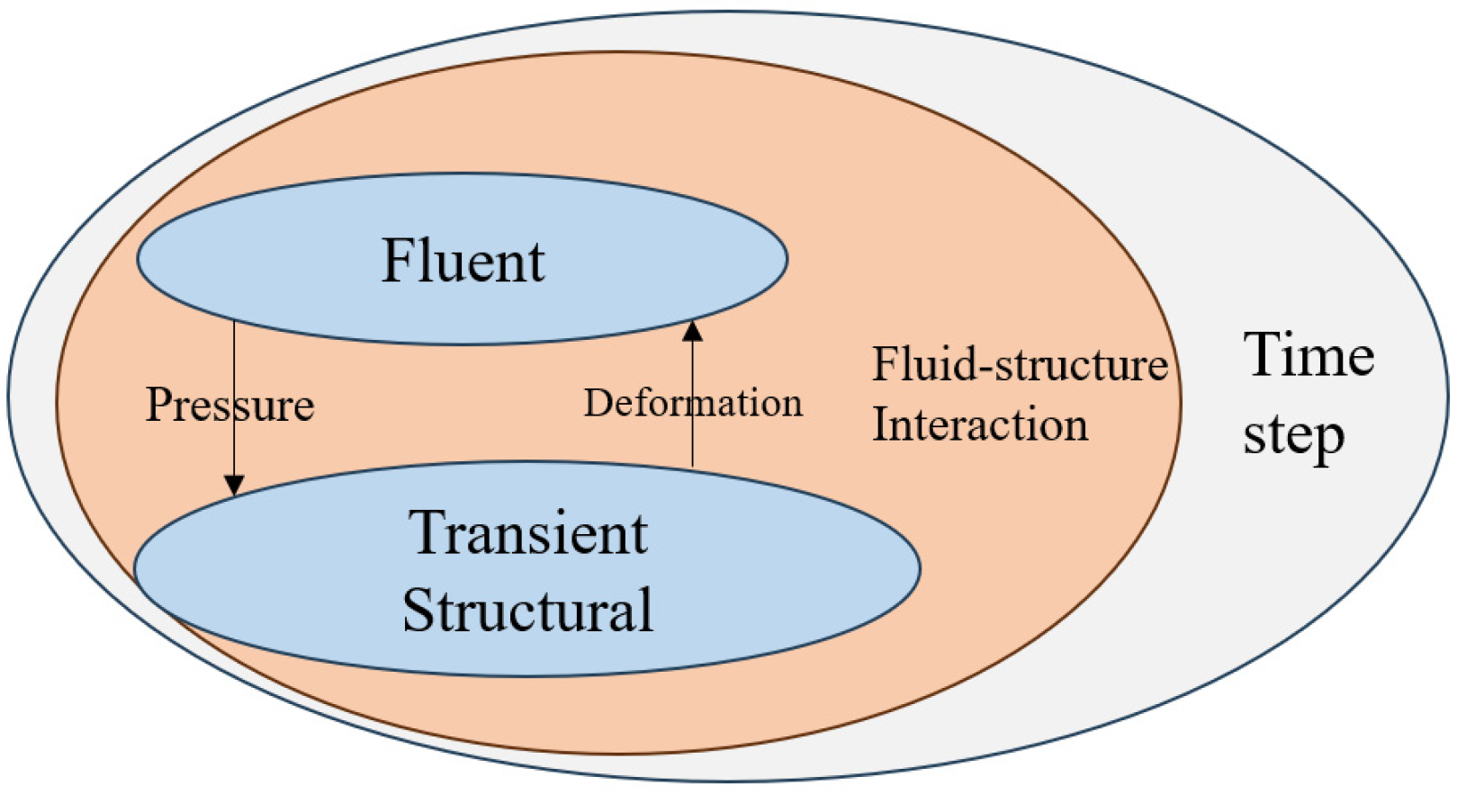
2.1. Two-Way Fluid–Structure Interaction

To solve fluid–structure coupling problems [18], one must first derive fluid and structure solutions and establish their governing equations, which include fluid equations such as the continuity and momentum conservation equations and solid governing equations derived from Newton’s second law. In fluid–structure coupling, the pressure is the physical quantity obtained after the fluid calculation, while the displacement is the physical quantity obtained after the structural calculation. The key lies in establishing a connection between the two. Based on the method used to establish this connection, the fluid–solid coupling solution methods can be categorized into the direct solution and separate solution methods. The direct solution method establishes a fluid–solid coupling control equation that links fluid control equations and solid control equations. This ensures that the physical quantities at the interface between the fluid domain and the solid domain, such as force and displacement, remain consistent. As a result, a large matrix equation that encompasses both fluid and solid variables is formed, allowing for its resolution in the same solver. The separate solution method eliminates the need for fluid–solid coupling control equations. The fluid solver (Fluent) and structural solver (Mechanical) are utilized to solve for the fluid and structural domains, respectively. Subsequently, the transfer of data between the two takes place.
While direct solution methods offer higher computational accuracy, solving complex, large-scale fluid–structure interaction problems poses challenges in terms of convergence and resource consumption. Therefore, to address the fluid–structure–soil interaction problem presented in this paper, a separation approach provided by Ansys was employed. This approach involves the use of the two-way fluid–structure coupling method, as illustrated in the Figure 1 below.

2.2. Volume of Fluid (VOF) Model

The Volume of Fluid (VOF) model [19] is extensively applied in simulating the sloshing of oil tanks and belongs to the computational fluid dynamics (CFD) method. The model considers the sum of volume fractions for all components to be 1. By defining the volume fraction of each phase, the movement of each phase can be tracked and the interfaces between phases can be determined. The multiphase model described in this paper is a two-phase model, with the two phases centering upon air and liquid, respectively. It assumes the volume fraction of the air phase to be αair. In each computational unit, three possible scenarios may occur [20].
(1)
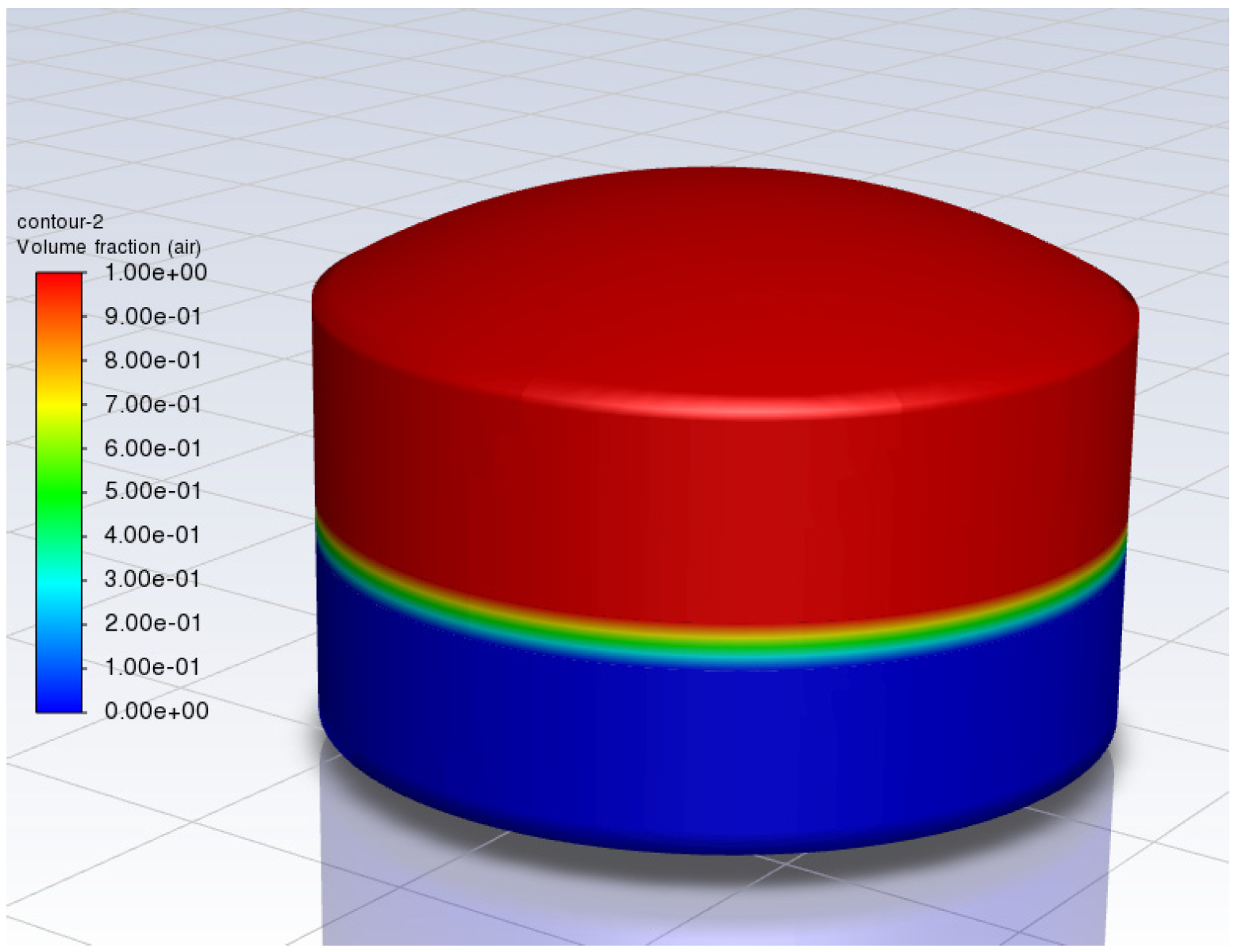
αair = 1: The calculation element is entirely filled with the gas phase, as indicated by the red portion in the Figure 2.
(2)
αair = 0: The calculation element is completely filled with the liquid phase, as depicted by the portion in the blue.
(3)
0 < αair < 1: The calculation element is partially filled with the liquid phase, and the point where αair = 0.5 can be defined as the LNG liquid surface.
The control equations of the VOF model are based on the Navier–Stokes equations, and one must consider the influence of gravity and surface tension during the calculations. The control equations for the VOF model are follows:
Continuity equation:
ρ t + ( ρ u ) = 0
Momentum equation:
( ρ u ) t + ( ρ u u ) = p + ρ g + [ μ ( u + u T ) ] + F C S F
Energy equation:
( ρ E ) t + ( ρ u ( ρ E + p ) ) = ( k e f f T ) + m ˙ lg h lg
where ρ is the fluid density, u is the velocity vector, p is the pressure, μ is the dynamic viscosity, g is the gravitational acceleration, FCSF is the surface tension term, E is the energy, T is the temperature, and keff is the effective thermal conductivity. The material properties presented in the equations are determined by the presence of each phase in each fluid volume.
FCSF is calculated by the continuum surface force (CSF) model [21]:
F C S F = 2 σ l v × α l ρ l C v α v + α v ρ v C l α l ρ l + ρ v
where σlv is the surface tension pressure; C is the surface curvature.
The subscript l is the liquid phase, and v is the air phase.

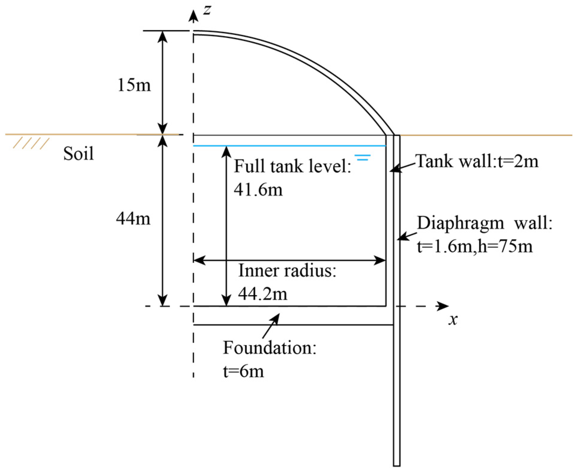
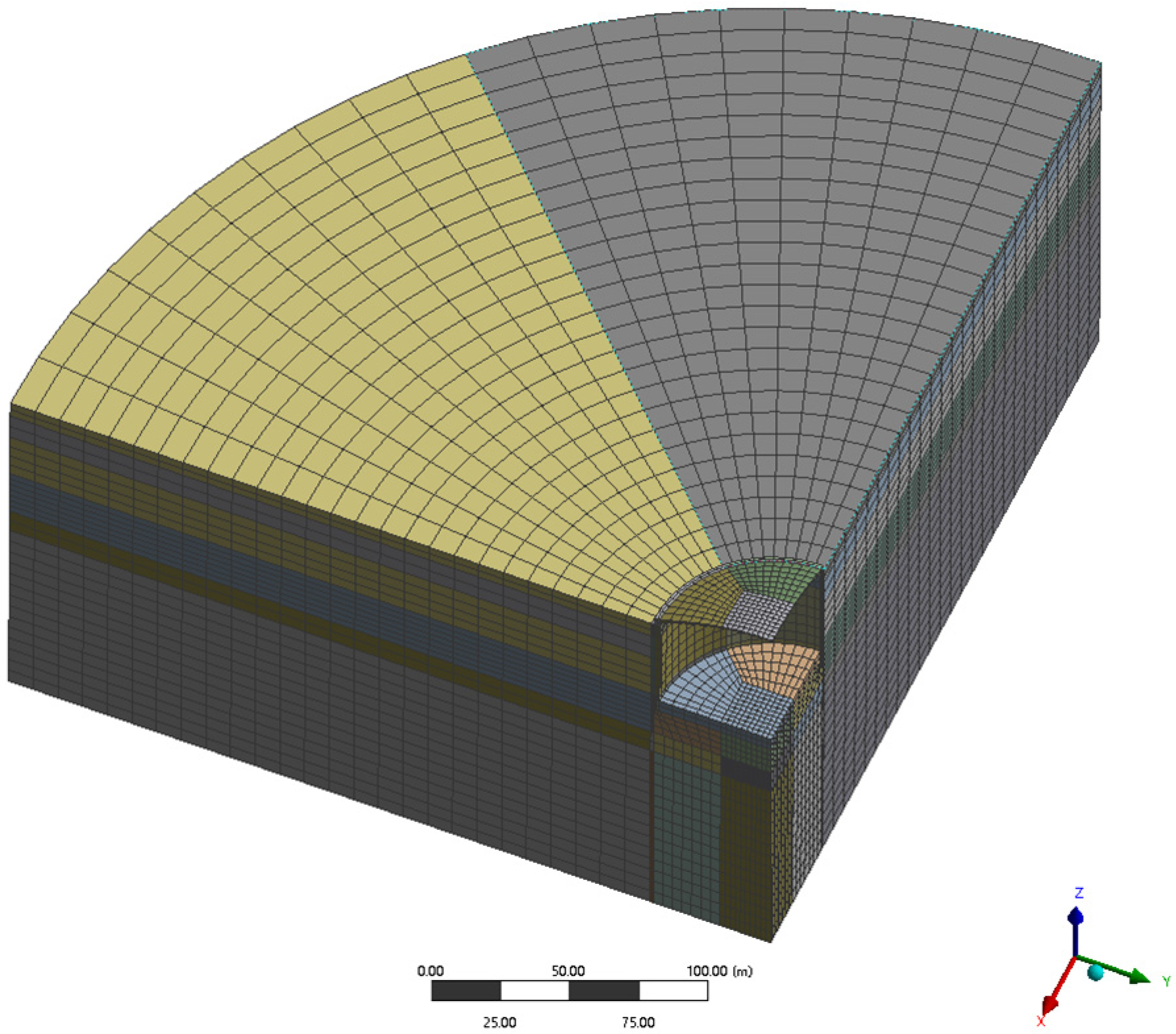
2.3. Finite Element Model

When practically modeling storage tanks, it is important to employ appropriate simplifications. As illustrated in Figure 3 and Figure 4, the analysis model for underground tanks encompasses the LNG tank itself (including the tank body, dome, and base plate), along with the retaining wall and geological layers, while disregarding the inner tank and other ancillary structures. Table 1 shows the parameters of soil layers and structural materials. The study uses an equivalent linearization method [22] to account for the nonlinear characteristics of soil. The soil adopts the Mohr–Coulomb constitutive model and is assumed to be an isotropic homogeneous stratum. The storage tank is a reinforced concrete structure consisting of a concrete damaged plasticity model (CDP) with a damping ratio of 0.05. To mitigate seismic wave reflections at the soil boundaries, the diameter of the cylindrical soil was set as 600 m, which is six times the excavation diameter, and the depth was set as 164 m. The bottom was fixed as a boundary, the cylindrical sides were constrained to the normal surface, and the upper surface of the soil was entirely free. The model does not consider the effects of groundwater and low temperature. Detailed parameters can be found in Table 2.
The geometric dimensions of the underground storage tank are shown in Figure 3. The aboveground tank and the underground tank had the same dimensions, and both had a storage capacity of approximately 270,000 m3. The inner radius of the concrete tank was 44.2 m, with a wall thickness of 2 m and a bottom plate thickness of 6 m. In addition, there were diaphragm walls on the outer side of the underground tank with a depth of 75 m and a thickness of 1.5 m. The foundation of the aboveground tank was reinforced instead of the diaphragm walls.
Figure 4 shows the mesh of the underground tank model. Both the soil and the structure are represented as solid elements (solid185), with the upper surface in contact with the tank’s bottom plate having a friction coefficient of 0.4. The fluid portion was modeled using the VOF model. After meshing, the total number of mesh elements in the aboveground tank model was 125,540, while the underground tank model had a total of 114,560 mesh elements. The maximum size of the elements was smaller than one-eighth of the wavelength, satisfying the required calculation accuracy.

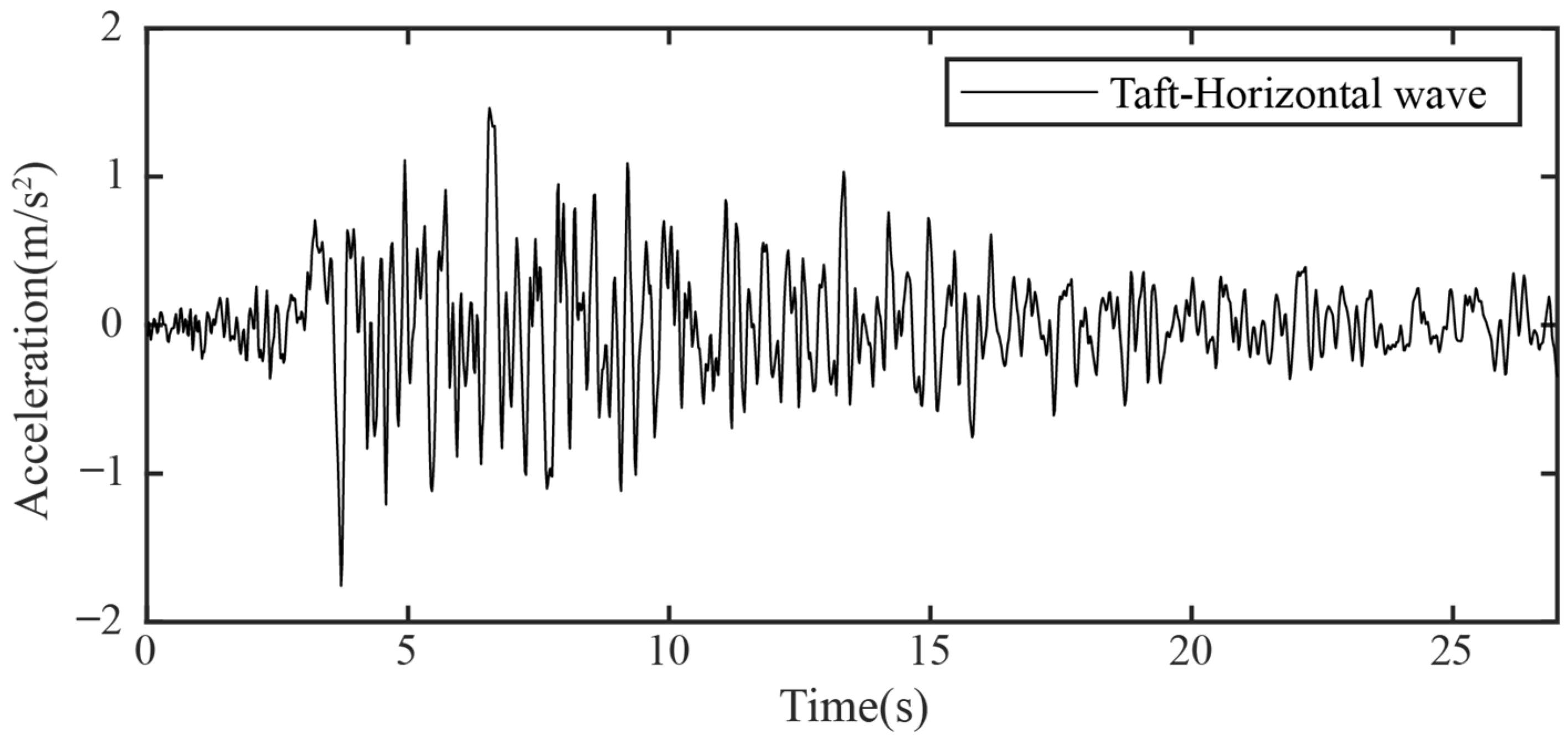
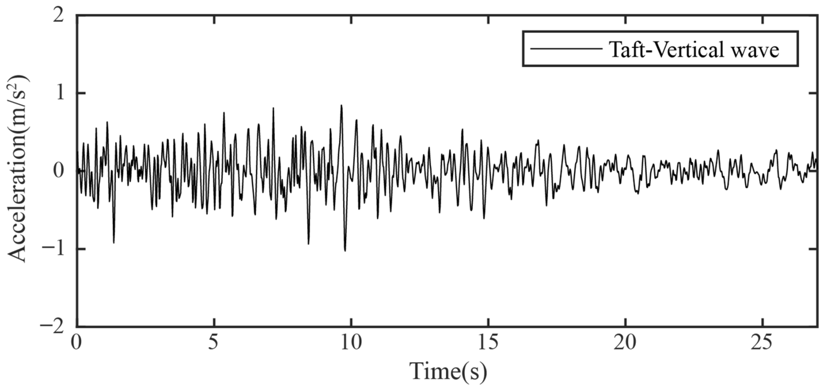
2.4. Earthquake Parameters

In China, the seismic design specifications for large LNG storage tanks are based on reference [23], and specific design regulations have been formulated for large petroleum storage tanks. To more comprehensively and truthfully reflect situations wherein storage tanks are placed under stress from earthquake activity, taking into account the site category of the building and the seismic design grouping, the acceleration time history curve of actual natural earthquake records was selected to analyze the tanks’ seismic responses. The relevant parameters of the selected seismic wave are as follows: Taft earthquake record (21 July 1952, California earthquake, 7.4 Magnitude), with an interval of 0.02 s and a duration of 54.40 s, with the peak acceleration occurring at 3.72 s and a peak value of 1.759 m/s2 (horizontal). Figure 5 and Figure 6 show the horizontal (x-axis) and vertical (z-axis) acceleration time histories of the Taft earthquake wave.

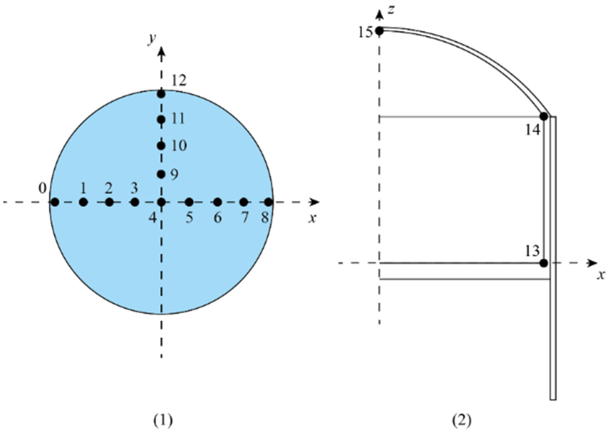
2.5. Monitoring Reference Points

To better observe the oscillation of the LNG liquid under seismic activity, several nodes on the surface of the LNG were selected to monitor vertical wave height. The liquid level in the full tank reached a depth of 41.6 m. The monitoring reference points on the liquid surface are illustrated in Figure 7(1), with thirteen points all located on the x and y axes. The coordinates of reference point 4 (RP4) were (0, 0), while RP 0 was located at (−44, 0), RP 8 was located at (44, 0), and RP 12 was located at (0, 44). The remaining nodes were uniformly distributed along the coordinate axes. Additionally, two measuring points on the storage tank’s structure, located at the top and bottom of the tank wall, were selected to primarily monitor the tank acceleration and the relative displacement of the tank along the x-axis.

3. Results and Discussion

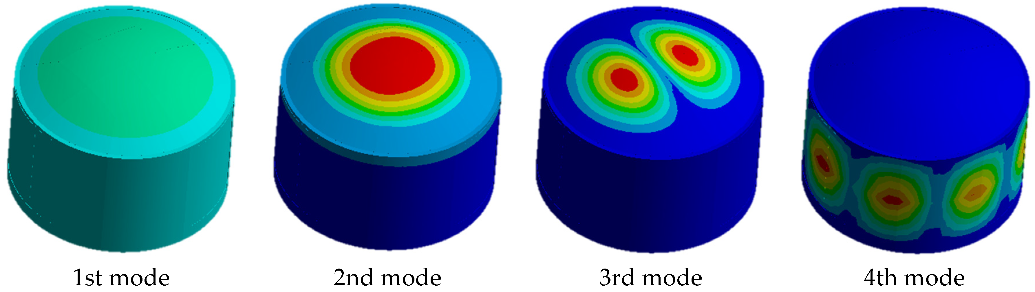
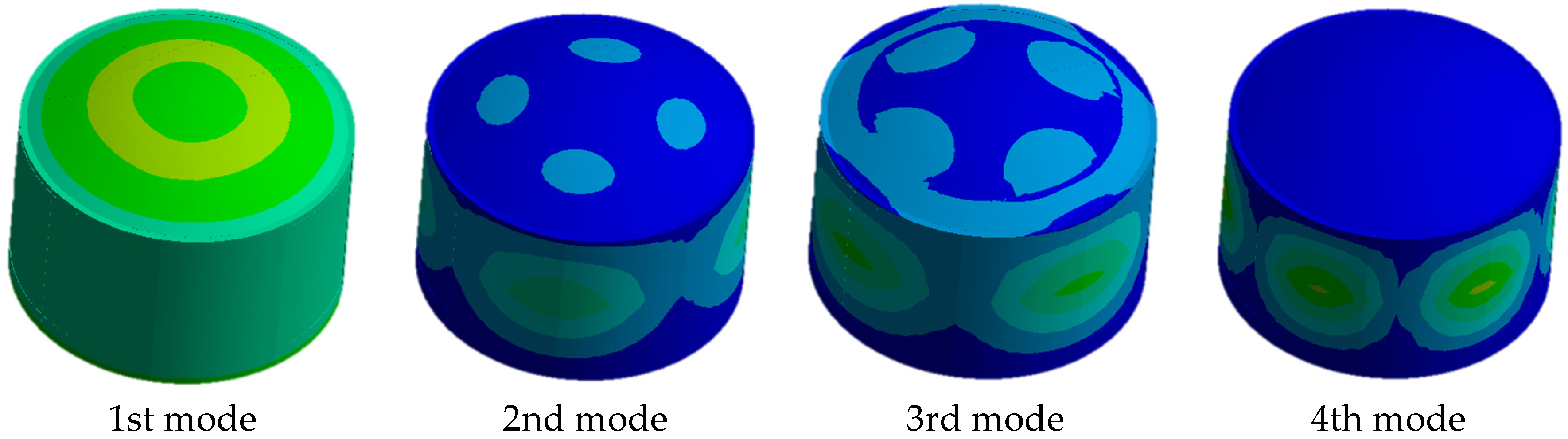
3.1. Modal Analysis of LNG Tanks

Before carrying out dynamic analyses of structure, it is imperative to initiate a modal analysis to comprehend the inherent vibrational characteristics of the structure, laying the groundwork for subsequent dynamic analyses. Typically, the modalities of a structure can be categorized into dry modes and wet modes, depending on whether the influence of surrounding fluids is taken into consideration. Given the presence of liquid within the tank, the modal analysis for tanks differs from that of general structures, necessitating the inclusion of the impact of liquid on the tank, thus constituting wet modal analysis.
Within the Ansys Workbench, the application of the acoustic–structural coupling algorithm in the Modal Acoustics module facilitates the completion of wet modal analysis. Disregarding the influence of the soil and focusing solely on the modal analysis of the fluid–structure coupling model, the tank bottom is subjected to fixed constraints, with the internal liquid being water. Moreover, our analysis did not account for the influence of air within the tank. The depth of a full LNG tank is 41.6 m. The natural frequencies corresponding to the dry and wet modes of the storage tank, as computed, are presented in Table 3. Figure 8 and Figure 9 show the first four modes of empty and full tanks, respectively. The modal frequency of a tank filled with LNG is notably lower than that of an empty tank.
According to the method proposed by Xiang Zhongquan [24] and SK Jain et al. [25], the frequencies of the tank structure were calculated separately for the empty-tank and full-tank states.
Empty tank modal [24]:
f r = f 1 ξ 1 α f 1 = 1 4 H G 2 ρ s ξ 1 = 1 π 2 64 R H 2 1 μ α = 1 + 0.1 1 + μ H R 2 1 2
where f1 is the fundamental period of shear vibration for the beam; α is the influence coefficient for bending deformation; ξ1 represents the influence coefficient for cross-sectional deformation; ρs is the density of the material used for the outer tank wall; H is the height of the outer tank wall; μ represents the Poisson’s ratio of the tank wall material; and G represents the shear modulus of the tank wall material.
Full tank modal [25]:
T i = C i h ρ t E / D
where Ci is a coefficient related to h/D, set at 4.4; D is the inner diameter of the storage tank; t is the thickness of the tank wall; h represents the height of the liquid surface (m); ρ is the liquid density; and E is the elastic modulus of the tank wall material.
The calculated results are shown in Table 4. The results indicate that the error between the simulation results obtained using ANSYS and the results calculated using the theoretical method is less than 10%.

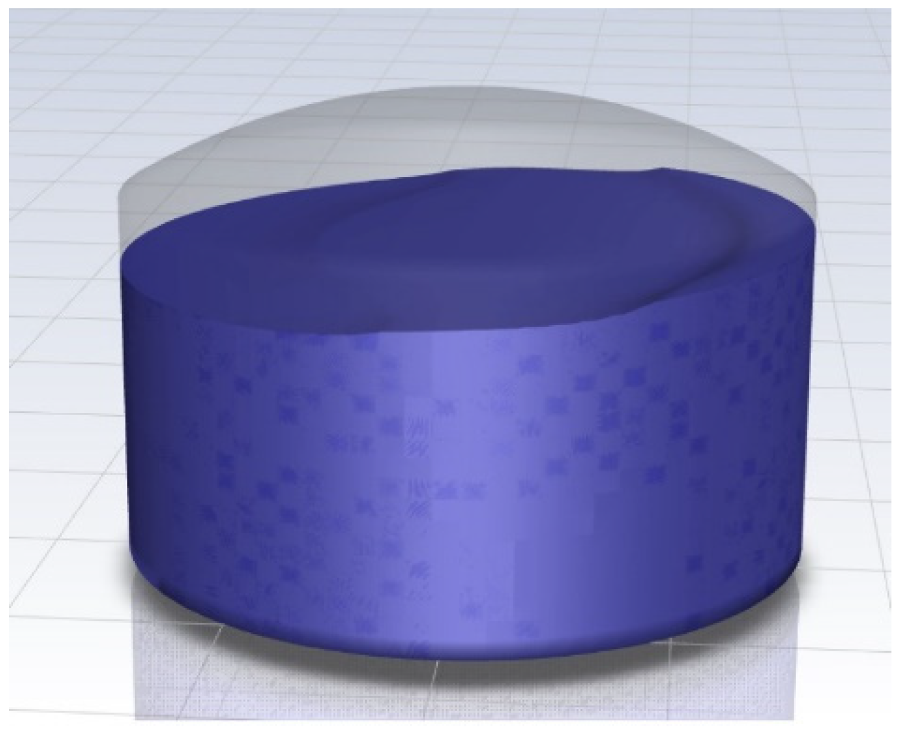
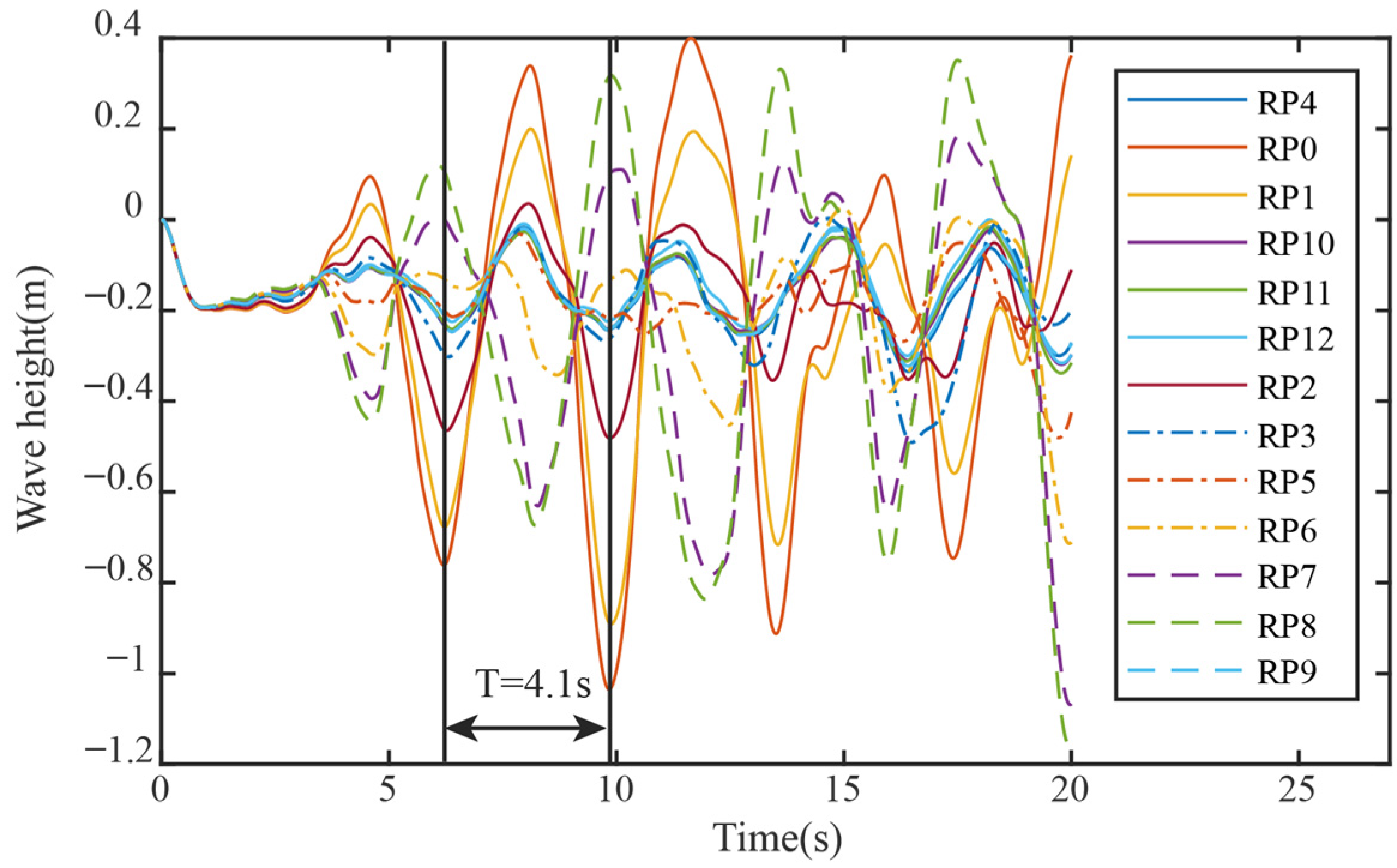
3.2. Fluctuations in the LNG

Figure 10 shows the calculation results for the full tank, the depth of which is 41.6 m. The blue part represents the LNG fluid, which fluctuates under the influence of earthquakes. In Figure 11 and Figure 12, the curves show the variation in wave height at the monitoring points on the LNG surface over time. From the graph, it can be discerned that, along the x-axis, under the influence of seismic activity, the farther it gets from the center, the more pronounced the wave amplitude becomes, signifying more intense liquid oscillations. It is worth noting that the wave height is highest at RP 0 (approximately 0.392 m for aboveground tanks and 0.284 m for underground tanks). The fluctuation amplitude of aboveground tanks is significantly greater than that of underground tanks. At RP 8, the peak wave height is slightly smaller than at RP 0. Along the y-axis, the temporal waveforms of the liquid level exhibits similarity, along with minimal disparity in wave height. At the same time, the fluctuation period of LNG in aboveground tanks is about 4.1 s, while that in underground tanks is about 1.9 s. This indicates that the constraint of soil can reduce the height and fluctuation period of LNG waves. Because excessive waves will impact the ceiling of the tank and cause adverse effects, underground full tanks are safer than aboveground full tanks.

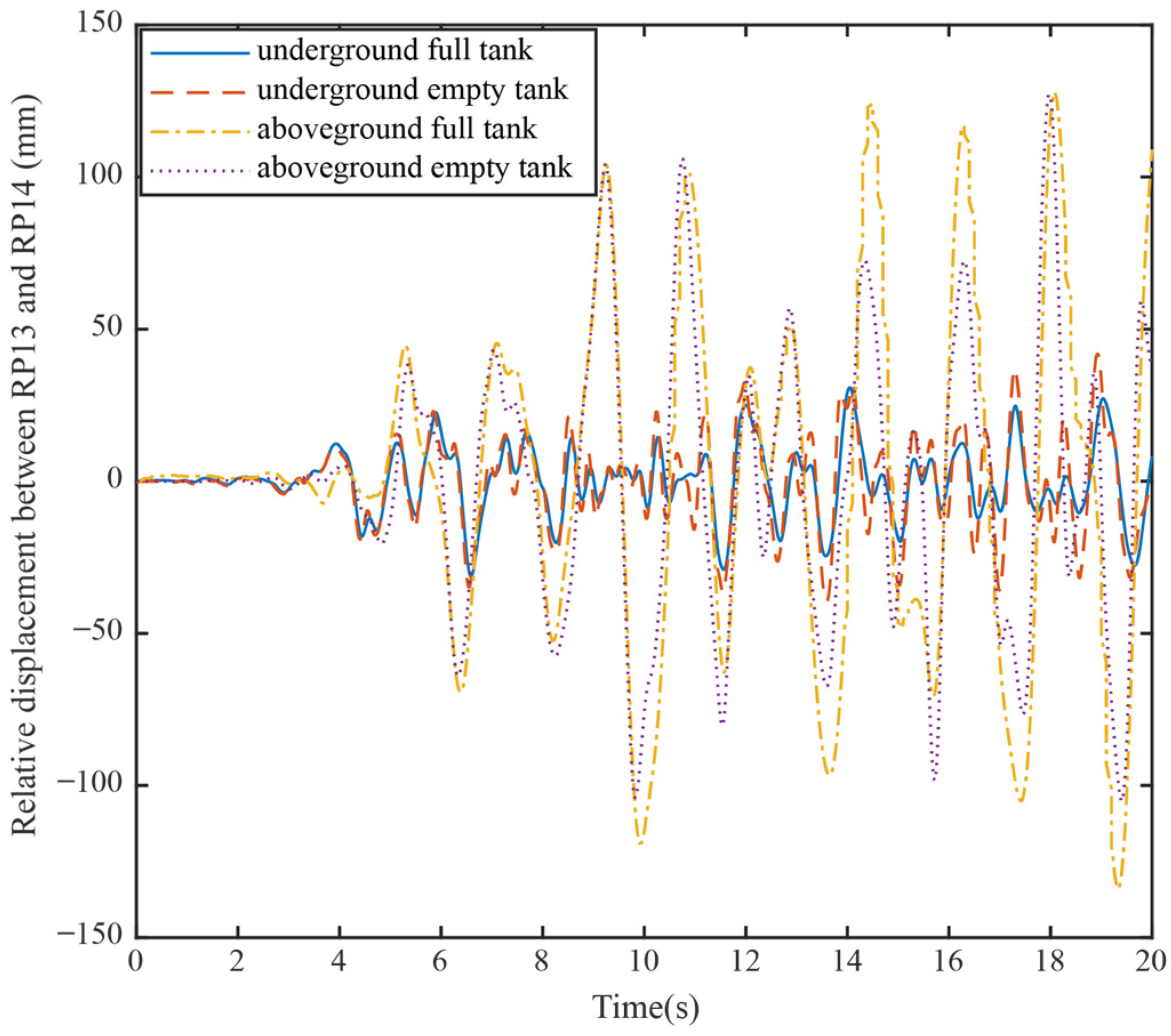
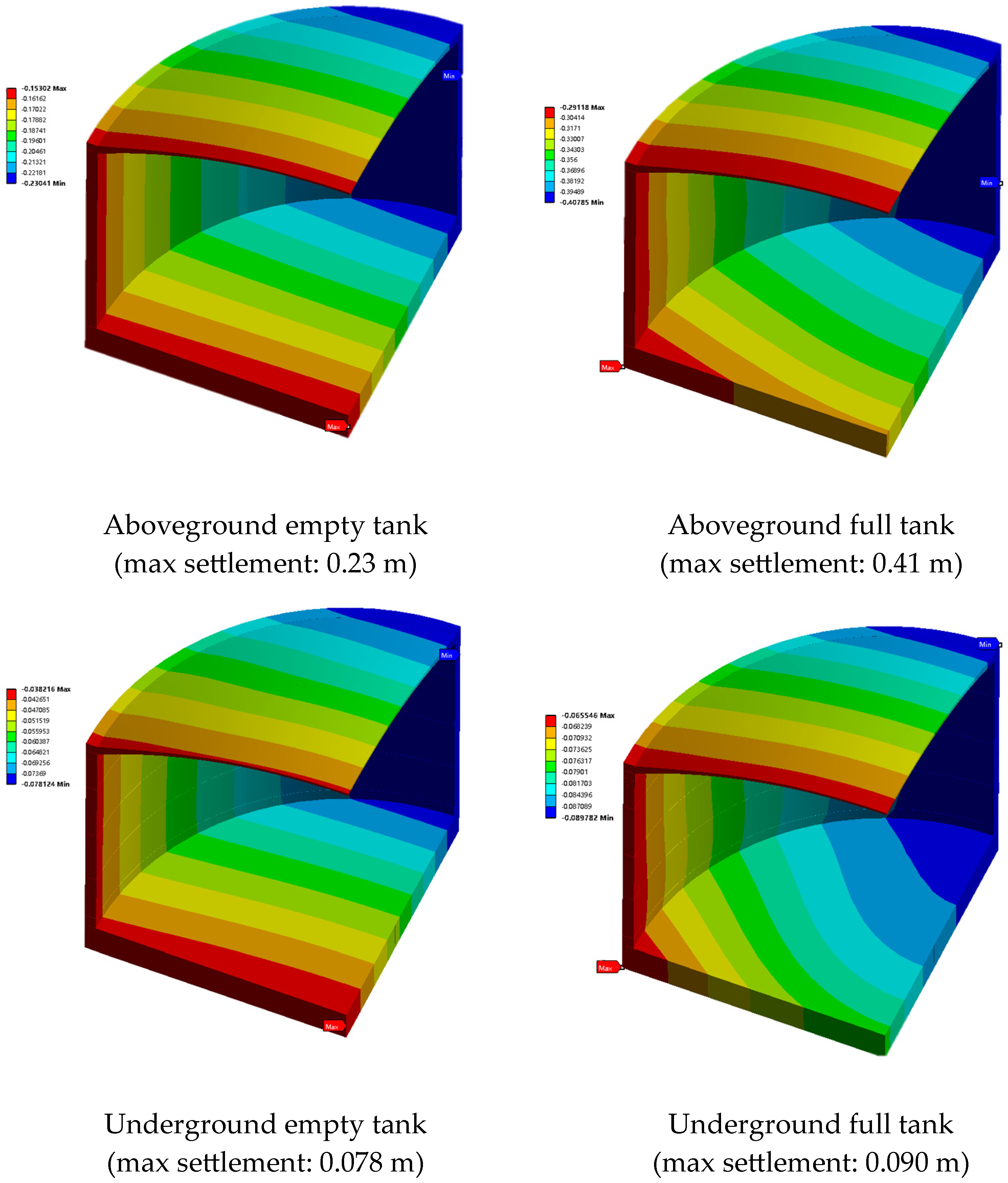
3.3. Tank Deformation

Both the aboveground and underground tanks have liquid levels at depths of 0 m and 41.6 m, respectively. The maximum relative horizontal displacement of the external tank wall (between RP13 and RP14) when subject to horizontal seismic activity is shown in Figure 13. For the aboveground empty tank, the max relative displacement is 122 mm, which is less than that of the full tank (136 mm). Meanwhile, for the empty underground tank, the max relative displacement is 41.5 mm, smaller than the aboveground tank’s deformation but slightly higher than that of the full underground tank (37 mm). It can also be seen that the shaking frequency of the aboveground tank is lower than that of the underground tank. These results indicate that the soil constraint around the underground tank reduces its deformation and improves the safety of the tank during earthquakes.
According to Figure 14, which illustrates the settlement nephogram of storage tanks, we can discern the following patterns: The maximum settlement of aboveground tanks is significantly higher when full (0.41 m) compared to when empty (0.23 m), indicating that the tank’s own weight and the pressure of the liquid inside result in greater load on the foundation, leading to greater settlement. In contrast, the maximum settlement of underground tanks is notably lower than that of aboveground tanks, whether empty (0.078 m) or full (0.090 m). This is likely due to the underground structure being supported by the surrounding soil, which mitigates settlement. Additionally, the difference in settlement between the full and empty states of underground tanks is minimal, which may relate to the design and construction quality of underground tanks and reflects their stronger adaptability to load changes.
Evaluating the results from the four diagrams, we can conclude that underground tanks have a clear advantage in seismic design, especially in controlling foundation settlement. Aboveground tanks exhibit greater settlement, which may necessitate stricter foundation treatment and structural reinforcement measures. With their lower settlement values, underground tanks demonstrate better stability and reliability, which is particularly important for tank design in earthquake-prone areas.

3.4. Stress and Acceleration

Under earthquake activity, the acceleration and von Mises stress of the storage tanks in four different states exhibit different patterns. Maximum von Mises stress and acceleration values of tank wall are shown in Table 5. The maximum von Mises stress and shear force of the aboveground and underground tanks are located at the bottom of the tank wall, and the maximum acceleration is generally located near the dome at the upper part of the wall. Due to the influence of LNG, the structural acceleration of the full tank is smaller than that of the empty tank, and the acceleration of the aboveground tank is greater than that of the underground tank. Due to the load of soil, the stress of the underground tank is greater than that of the aboveground tank. The stress of the full underground tank is slightly smaller than that of the empty underground tank. The stress of the empty aboveground tank is the smallest. This indicates that soil pressure is the main load on the underground tank structure, which increases the compressive stress on the concrete wall and reduces tank acceleration. After storing full LNG in the underground tank, the liquid pressure can balance part of the soil pressure outside the tank, making the full tank safer than the empty tank. The results show that underground tanks have better safety performance than aboveground tanks under earthquake activity.
Furthermore, the seismic response of the storage tank was evaluated under the influence of the EI-Centro seismic wave event (Southern California, 18 May 1940, with a magnitude of 6.9 and a peak ground acceleration of 3.41 m/s2). Comparative analysis with the Taft earthquake revealed that the EI-Centro event induced a significant escalation in the maximum von Mises stress, maximum acceleration, and relative deformation of the storage tank. Notably, the aboveground storage tanks exhibited a more pronounced increase in these parameters, suggesting a heightened susceptibility to seismic instability.
To elucidate the influence of soil properties and geological conditions on the seismic response of storage tanks, we manipulated the soil’s elastic modulus by increasing it by 50% and re-conducted the calculations. The augmentation of the soil’s elastic modulus resulted in a decrease in the structural stress and deformation, thereby implying a mitigating effect on the structural response. Conversely, an increase in acceleration was observed, which suggests that soft soil conditions have the potential to amplify seismic responses. Hence, constructing underground storage tanks in hard soil enhances the structure’s safety.
The results indicate that underground tanks demonstrate superior safety performance under seismic activity compared to aboveground tanks, primarily due to the stabilizing support provided by the soil. The safety of underground tanks is further enhanced in the full state due to the balancing effect of the liquid pressure. However, the intensity of seismic waves and soil conditions significantly affect the stress and acceleration experienced by the tanks, necessitating careful consideration of these factors in the design process. Particularly in regions with soft soil, the design of underground tanks should be approached with heightened caution.

3.5. Limitation and Improvements

This article employs ANSYS for fluid–solid coupling analysis, utilizing both VOF and FEM models. While ANSYS is robust software, it does have its limitations, such as demanding large computational resources and cumbersome grid generation. Consequently, to enhance computational efficiency, some simplifications are applied to the model in this study. The VOF model may face challenges with numerical dissipation and uncertainties in interface thickness and shape. The simplified FEM model may also bring inaccurate results.
Simultaneously, the subzero temperatures associated with LNG often induce freezing in the outer layers of the tank, thereby altering the dynamic characteristics of the soil layers, and further complicating the computational challenges. Consequently, with respect to future research, it is imperative to account for the influence of temperature fields and groundwater seepage fields to allow for a thermal–fluid–structure coupling analysis.

4. Conclusions

This study carried out numerical simulations to investigate the seismic responses of both aboveground and underground LNG storage tanks, considering the combined effects of the FSSI. Through employing the VOF and FEM models, this study conducted simulated calculations of two-phase flow for the LNG liquid inside the tanks. Based on this study, the following conclusions can be drawn:
(1)
After computing the modes of empty and full LNG storage tanks on the ground, we found that the frequency of full tanks is lower (3.193 Hz) than that of empty ones (3.714 Hz).
(2)
Due to the soil restraining the structure, the period and height of the liquid sloshing wave in underground tanks are 0.284 m and 1.9 s, smaller than those in aboveground tanks (0.392 m, 4.1 s). Excessive waves will impact the ceiling of the tank, causing adverse effects. Thus, underground full tanks are safer than aboveground full tanks.
(3)
Under earthquake loads, the deformation, acceleration, and stress of aboveground and underground tanks exhibit distinct patterns. The maximum relative horizontal displacement of an aboveground tank in a full state (136 mm) exceeds that in an empty state (122 mm), indicating that liquid sloshing significantly impacts the tank’s structure. The maximum story drift of the underground full tank wall (37 mm) is less than that in an empty tank (41.5 mm). Meanwhile, both the acceleration and displacement of underground tanks are lower than those of aboveground tanks. Due to the influence of soil pressure, the stress in underground tanks exceeds that in aboveground tanks, both in the empty and full states.
(4)
The seismic response varies under different waves. Soft soil also has an amplifying effect on the deformation and stress response of structures. Therefore, in the seismic response analysis of structures, it is necessary to conduct parametric analysis under various seismic motions to ensure the safe operation of storage tanks under multiple seismic waves.
Overall, underground tanks offer several advantages, including good seismic performance, land resource conservation, and relatively lower total costs. They are well suited for areas prone to earthquakes or where land resources are limited, making them deserving of wider application. At the same time, considering the groundwater seepage field and the characteristics of low-temperature LNG, further research is needed on the effects of thermal–fluid–structure coupling interactions.

Author Contributions

Conceptualization, Y.Z. and H.L.; methodology, G.J.; validation, Y.Z.; formal analysis, X.X.; investigation, G.J. and M.Z.; resources, X.X.; data curation, Y.Z. and M.Z.; writing—original draft preparation, Y.Z.; writing—review and editing, X.X. and G.J.; visualization, M.Z.; project administration, X.X. and G.J.; funding acquisition, X.X. All authors have read and agreed to the published version of the manuscript.

Funding

National Key R&D Program of China: grant nos. 2023YFC3806701, 2023YFC3806702, 2023YFC3806705; National Natural Science Foundation of China: grant nos. 52038008, 52378408; Science and Technology Innovation Plan of Shanghai Science and Technology Commission: grant nos. 22dz1203004, 23YF1451400; State Grid Shanghai Municipal Electric Power Company: grant no. 52090W23000B.

Institutional Review Board Statement

Not applicable.

Informed Consent Statement

Not applicable.

Data Availability Statement

Embargo on data due to commercial restrictions.

Conflicts of Interest

Authors Guolong Jin, Yonglai Zhang and Hongqiao Li were employed by the company China Shipbuilding NDRI Engineering Co., Ltd. Author Mingrui Zhao was employed by the company CNOOC Gas and Power Group Co., Ltd. The remaining authors declare that the research was conducted in the absence of any commercial or financial relationships that could be construed as a potential conflict of interest.

References

  1. Farasat, N.; Farasat, A.; Heysami, A.R.; Moridi, N. A Review of the Literature on the Underground (Buried) Storage Tanks. J. Appl. Environ. Biol. Sci. 2015, 5, 737–747. [Google Scholar]
  2. He, M. The Risk Evaluation of Transportation and Storage on Liquefied Natural Gas; Tongji University: Shanghai, China, 2007. [Google Scholar]
  3. Yu, T.; Dai, X. Fault Tree Analvsis of Fire Blast Accidents Caused by LNG Tanks. China Saf. Sci. J. 2007, 8, 110–114. [Google Scholar]
  4. Hosseini, S.E.A.; Beskhyroun, S. Fluid Storage Tanks: A Review on Dynamic Behaviour Modelling, Seismic Energy-Dissipating Devices, Structural Control, and Structural Health Monitoring Techniques. Structures 2023, 49, 537–556. [Google Scholar] [CrossRef]
  5. Housner, G.W. Dynamic Pressures on Accelerated Fluid Containers. Bull. Seismol. Soc. Am. 1957, 47, 15–35. [Google Scholar] [CrossRef]
  6. Veletsos, A.S. Seismic Effects in Flexible Liquid Storage Tanks. In Proceedings of the 5th World Conference on Earthquake Engineering, Rome, Italy, 25–29 June 1973; Bulletin of the Seismological Society of America: McLean, VA, USA, 1974; Volume 1, pp. 630–639. [Google Scholar]
  7. Haroun, M.A. Vibration Studies and Tests of Liquid Storage Tanks. Earthq. Eng. Struct. Dyn. 1983, 11, 179–206. [Google Scholar] [CrossRef]
  8. Malhotra, P.K.; Wenk, T.; Wieland, M. Simple Procedure for Seismic Analysis of Liquid-Storage Tanks, Structural Engineering International. J. Int. Assoc. Bridge Struct. Eng. 2000, 10, 197–201. [Google Scholar] [CrossRef]
  9. Sun, J.; Cui, L.; Zhang, Y.; Zhao, C. Research on seismic responses of storage-tanks considering soil-structure interaction. Earthq. Eng. Eng. Vib. 2010, 30, 141–146. [Google Scholar]
  10. Zheng, J.; Sun, J. Seismic response of LNG Storage Tank with Base Isolation Considering Pile-Soil. Earthq. Eng. Eng. Dyn. 2014, 34, 223–232. [Google Scholar]
  11. Ibrahim, R.A. Liquid Sloshing Dynamics: Theory and Applications; Cambridge University Press: Cambridge, UK, 2005. [Google Scholar]
  12. Sierikova, O.; Strelnikova, E.; Degtyarev, K. Seismic Loads Influence Treatment on the Liquid Hydrocarbon Storage Tanks Made of Nanocomposite Materials. Wseas Trans. Appl. Theor. Mech. 2022, 17, 62–70. [Google Scholar] [CrossRef]
  13. Livaoglu, R. Investigation of Seismic Behavior of Fluid–Rectangular Tank–Soil/Foundation Systems in Frequency Domain. Soil Dyn. Earthq. Eng. 2008, 28, 132–146. [Google Scholar] [CrossRef]
  14. Nicolici, S.; Bilegan, R.M. Fluid Structure Interaction Modeling of Liquid Sloshing Phenomena in Flexible Tanks. Nucl. Eng. Des. 2013, 258, 51–56. [Google Scholar] [CrossRef]
  15. Zhao, Y.; Li, H.; Fu, X.; Zhang, S.; Mercan, O. Seismic Analysis of a Large Lng Tank Considering the Effect of Liquid Volume. Shock Vib. 2020, 2020, 8889055. [Google Scholar] [CrossRef]
  16. Tomohiko, T.; Risa, K.; Kaoru, Y.; Satoshi, T.; Tetsuya, I. Coupled heat and water response analysis of LNG tank using multi scale integrated model. J. Jpn. Soc. Civ. Eng. 2019, 75, 125–141. [Google Scholar]
  17. Tomohiko, T.; Hiroyuki, Y.; Taira, Y.; Masato, N.; Tatsuya, Y. A study on seismic performance evaluation and evaluation of bearing capacity of LNG underground tank. J. Jpn. Soc. Civ. Eng. 2020, 76, 152–162. [Google Scholar]
  18. Benra, F.; Dohmen, H.J.; Pei, J.; Schuster, S.; Wan, B. A Comparison of One-Way and Two-Way Coupling Methods for Numerical Analysis of Fluid-Structure Interactions. J. Appl. Math. 2011, 2011, 853560. [Google Scholar] [CrossRef]
  19. Gopala, V.R.; Van Wachem, B.G. Volume of Fluid Methods for Immiscible-Fluid and Free-Surface Flows. Chem. Eng. J. 2008, 141, 204–221. [Google Scholar] [CrossRef]
  20. Wu, S.; Ju, Y.; Lin, J.; Fu, Y. Numerical Simulation and Experiment Verification of the Static Boil-Off Rate and Temperature Field for a New Independent Type B Liquefied Natural Gas Ship Mock Up Tank. Appl. Therm. Eng. 2020, 173, 115265. [Google Scholar] [CrossRef]
  21. Brackbill, J.U.; Kothe, D.B.; Zemach, C. A Continuum Method for Modeling Surface Tension. J. Comput. Phys. 1992, 100, 335–354. [Google Scholar] [CrossRef]
  22. Schnabel, P.B. SHAKE, a Computer Program for Earthquake Response Analysis of Horizontally Layered Sites; Report No. EERC 72-12; University of California: Berkeley, CA, USA, 1972. [Google Scholar]
  23. Huang, S.; Wang, Y. Code for Seismic Design of Buildings; China Architecture & Building Press: Beijing, China, 2003. [Google Scholar]
  24. Xiang, Z.; Li, Q. Seismic Resistance of Vertical Storage Tank; Seismological Press: Beijing, China, 1990. [Google Scholar]
  25. Jain, S.K.; Jaiswal, O.R. Modified Proposed Provisions for Aseismic Design of Liquid Storage Tanks: Part I-Codal Provisions. J. Struct. Eng. SERC 2005, 32, 195–206. [Google Scholar]
Figure 1. Two-way fluid-structure interaction.
Applsci 14 04753 g001
Figure 2. Schematic diagram of VOF model.
Applsci 14 04753 g002
Figure 3. The geometric dimensions of the underground storage tank.
Applsci 14 04753 g003
Figure 4. Schematic diagram of grid division for model calculation.
Applsci 14 04753 g004
Figure 5. Horizontal acceleration time histories of the Taft earthquake (X-axis).
Applsci 14 04753 g005
Figure 6. Vertical acceleration time histories of the Taft earthquake (Z-axis).
Applsci 14 04753 g006
Figure 7. (1) LNG surface wave height measuring point; (2) tank structure measuring point.
Applsci 14 04753 g007
Figure 8. The first four modal shapes of a storage tank structure in the empty state.
Applsci 14 04753 g008
Figure 9. The first four modal shapes of a storage tank structure in the full state.
Applsci 14 04753 g009
Figure 10. LNG in tanks undulates under the influence of earthquake activity.
Applsci 14 04753 g010
Figure 11. Wave height monitoring curve of LNG in aboveground tanks.
Applsci 14 04753 g011
Figure 12. Wave height monitoring curve of LNG in underground tanks.
Applsci 14 04753 g012
Figure 13. The temporal curve of the maximum horizontal displacement of the tank wall.
Applsci 14 04753 g013
Figure 14. Settlement nephogram of storage tanks.
Applsci 14 04753 g014
Table 1. Material characteristics of the model.
Nameγ/kN·m−3c/kPaφ/(°)Elastic Modulus/MPaPoisson’s RatioDamping RatioLayer Thickness/m
① Filling18.2123.5240.320.077.5
③ sandy silt19.61028.5610.30.0712.5
④ clay17.4144200.310.0811.2
⑤ silt19.7431.5730.30.0710.3
⑥ clay19.12711640.310.0822.2
⑦ silt19.493062.50.310.0811.3
⑧ clay19.85614.5550.310.08
Diaphragm walls24 32,5000.200.05
Tank structure24 34,5000.200.05
Reinforcing steel7850 200,0000.3
Table 2. Material properties of LNG.
MaterialDensity (kg/m3)Sonic Speed (m/s1)Dynamic Viscosity (kg/(m·s)
LNG48015000.00113
Table 3. The first 10 modal frequencies of empty and full tanks.
Modal12345678910
Frequency of empty tanks (Hz)3.7146.9357.0197.0267.0287.0457.0707.0807.1067.113
Frequency of full tanks (Hz)3.1934.9764.9785.0315.0355.1925.2055.9725.9746.283
Table 4. The theoretical frequencies of empty and full tanks.
Numerical Simulation ResultTheoretical Calculation ResultRelative Error
Frequency of empty tanks (Hz)7.019 (4th mode)7.5036.79%
Frequency of full tanks (Hz)4.98 (2nd mode)5.529.9%
Table 5. Maximum von Mises stress and acceleration values of tank wall.
Taft WaveEI-CentroTaft Wave (Harder Soil)
Max Von Mises Stress (MPa) Max Acceleration (m/s2)Max Von Mises Stress (MPa) Max Acceleration (m/s2)Max Von Mises Stress (MPa) Max Acceleration (m/s2)
Underground full tank10.355.8112.828.029.626.37
Underground empty tank11.69.23
Aboveground full tank8.426.1711.368.637.877.05
Aboveground empty tank5.3510.04
Disclaimer/Publisher’s Note: The statements, opinions and data contained in all publications are solely those of the individual author(s) and contributor(s) and not of MDPI and/or the editor(s). MDPI and/or the editor(s) disclaim responsibility for any injury to people or property resulting from any ideas, methods, instructions or products referred to in the content.

