Article

Disturbance Observer-Based Anti-Shock Controller for Laser Beam Steering Systems

Ground Technology Research Institute, Agency for Defense Development, Daejeon 34186, Republic of Korea
Appl. Sci. 2024, 14(11), 4774; https://doi.org/10.3390/app14114774
Submission received: 28 April 2024 / Revised: 28 May 2024 / Accepted: 29 May 2024 / Published: 31 May 2024
(This article belongs to the Collection Optical Design and Engineering)

Abstract

:
This paper presents an approach for improving the robustness of tip-tilt controllers for fast-steering mirror (FSM)-based laser beam steering (LBS) systems in the presence of dynamic disturbances such as external shocks. To this end, we propose the addition of a disturbance observer (DOB)-based anti-shock controller in parallel to the original linear servo control loop to improve its control performance in the presence of external shocks. To increase the tip-tilt control performance against external shocks, the DOB-based control method, which is an improved control method for eliminating nonperiodic disturbances, is implemented in the original tip-tilt control system. The results indicate that the control error of the DOB-based anti-shock controller decreased, resulting in an efficient improvement in its disturbance-rejection performance.

1. Introduction

Fast-steering mirror (FSM)-based laser beam steering (LBS) systems are used extensively in various optical tracking control systems, such as line-of-sight stabilization, adaptive optics, and long-range laser communication [1,2,3]. Moreover, these systems are increasingly being mounted on mobile platforms such as spacecraft, satellites, airplanes, ships, and vehicles [4,5]. Therefore, the control precision of LBS systems must be improved to maintain the aiming point in the target plane while minimizing factors that cause jitter even under dynamic disturbances [6].
The robust design of FSM systems is typically approached from two perspectives. First, the design of structural parameters is considered to satisfy the control requirements of the target platform. FSM systems require flexible hinges as rigid elastic supports to achieve the desired structural stiffness and sustain driving forces for a certain range of strokes. Flexible hinges are designed and assembled to guarantee the required transmission resolution and accuracy, as well as to facilitate substantial rotation, because such hinges eliminate mechanical friction and sources of nonlinearity such as backlash, hysteresis, and static resistance [7,8]. In addition, flexible hinges do not require lubrication, have wide operating temperature ranges, and are more reliable than traditional bearings [9]. A flexible hinge should approximate a bearing connected to a mirror to ensure higher axial/torsional stiffness and lower rotational stiffness. However, the stiffness of flexible hinges in different directions is coupled, and therefore, axial/torsional stiffness cannot be considerably higher than rotational stiffness. In addition, reducing the rotational stiffness of a flexible hinge to expand its angular range inevitably reduces the axial/torsional stiffness. Second, to achieve high-precision control performance, it is necessary to design a control system with rapid response characteristics and strong disturbance-rejection control performance [10,11]. FSM systems typically use long-stroke voice coil actuators (VCAs) or high-actuation resolution piezoelectric (PZT) actuators, and their response, output force, and resolution are suitable for most applications. In particular, PZT actuators are more suitable than VCAs for use in applications that require higher actuation resolution and faster settling times. High-precision tip-tilt controllers for FSM systems are designed to ensure that the aforementioned VCAs or PZT actuators maintain an extremely small rotational position (under 10 μrad rms) in the presence of dynamic disturbances to satisfy the desired operating conditions. Therefore, several studies have been conducted to realize High-precision control performance. For instance, a method to eliminate the vibration effect of PZT actuators was proposed [12]. A notch filter was developed to effectively eliminate the main resonant mode of FSM systems [13]. In other studies, an input shape controller and an integral resonance controller were developed [14].
Primarily, two types of disturbances hinder the tip-tilt control of FSM systems: periodic and nonperiodic disturbances. First, periodic disturbances occur owing to the spinning of cooling fan units on the target platform. To eliminate periodic disturbances, repetitive controllers and adaptive feedforward cancellation (AFC) schemes have been applied [15,16]. Repetitive control technologies are the most widely used, either as internal or external model-based controllers [17]. Discrete-time repetitive controllers based on the internal model principle (IMP) have been synthesized and analyzed [18]. The most common approach is based on the IMP, which states that a model of the disturbance generation system must be included in the feedback system to realize disturbance cancellation. However, owing to hardware limitations of the servo loops used in FSM control systems, the classic AFC method cannot be used to precisely control rotational position. Second, nonperiodic disturbances occur when external shocks are applied to the target platform under operating conditions. Typically, the closed-loop bandwidth of the control system should be increased to ensure that the FSM system can eliminate the errors caused by such disturbances. However, doing so may reduce the stability of the FSM system owing to its increased sensitivity to high-frequency disturbance components. Consequently, a controller design that considers closed-loop bandwidth alone is inadequate [19,20]. Therefore, various studies have been conducted to design robust controls in the presence of external shocks, one of which is a robust control system that uses observer-based sliding mode control to manage shocks [21]. In addition, a direct measurement-based feedforward algorithm is proposed to suppress most of the theoretical external disturbances [22,23]. However, while the feedforward method works well in specific environments with low measurable noise, its implementation under more complex conditions is limited owing to the additional cost of another sensor.
To avoid the abovementioned problems, an emerging basic approach to suppressing disturbances can be used that estimates the influence of an external disturbance independently by using a disturbance observer (DOB) and then eliminating the perturbation by using the feedforward method. This feedforward method is called the DOB method [24,25]. It has been applied to several mobile devices with High-precision control systems, such as robot motion control, swing arm actuators in hard disk drives, VCAs in optical disk drives, and permanent magnet synchronous motor control [26,27,28]. To improve the control performance of the original control system for use in FSM systems, high open-loop gain is needed in the dynamic disturbance frequency domain to sufficiently attenuate disturbances. FSM systems commonly use high-bandwidth proportional-integral (PI) controllers owing to their robustness to modeling errors and simple implementation [29,30]. The addition of a DOB to the base controller significantly improves the disturbance attenuation performance because of its simplicity and suitability for real-time implementation [31,32].
In this study, we propose a more reliable anti-shock control algorithm by using a DOB to enhance the disturbance-suppression performance of FSM systems at low frequencies. The rest of this paper is organized as follows: Section 2 introduces the basic FSM control system. In Section 3, the DOB-based anti-shock controller is presented, and its performance is analyzed. Section 4 describes the experiments conducted to verify the proposed approach. Finally, our concluding remarks are presented in Section 5.

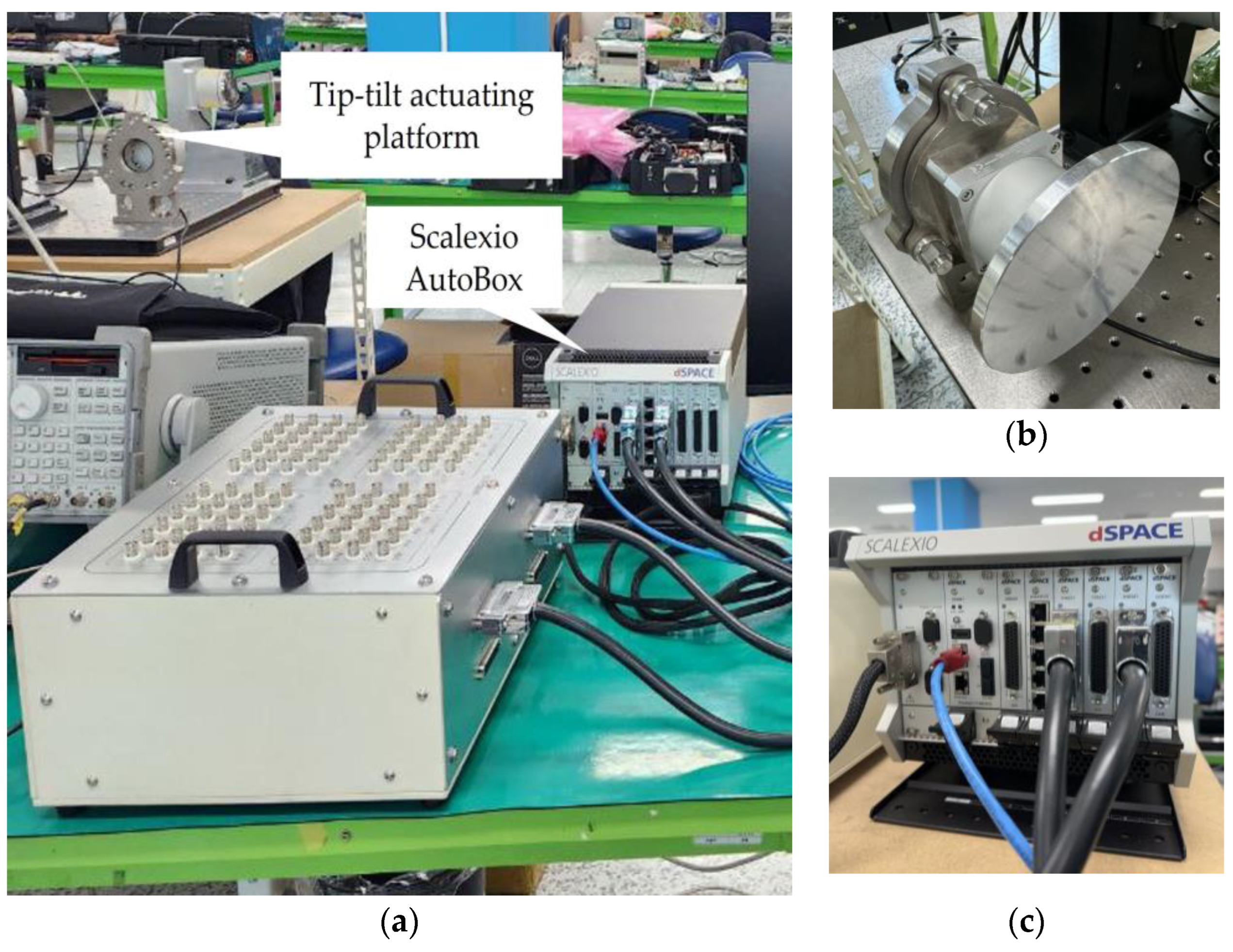
2. FSM Control System

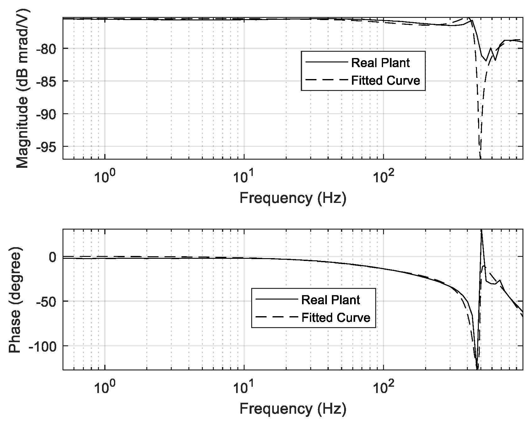
2.1. Dynamic Characteristics of PZT Actuator

In the conventional approach to designing a High-precision FSM control system for tip-tilt control, a PZT actuator is used. The frequency response function (FRF) of an actuating plant is typically obtained using the sine-sweep method. Meanwhile, the real plant considered herein consists of a PZT actuator, a DC-DC converter-type amplifier, and a sensor amplifier. The dynamic specifications of the real plant indicate that its resonance frequency is 450.2 Hz. The DC sensitivity, voltage amplifier gain, and sensor amplifier gain are 168.3 µrad/V, 10 V/V, and 0.0059 V/µrad, respectively. Therefore, the real plant can be modeled as the following fifth-order transfer function [33]:
P s = 6.08 × 10 3 S 3 + 7.09 × 10 6 S 2 + 5.85 × 10 10 S + 6.27 × 10 13 S 5 + 8.95 × 10 3 S 4 + 7.49 × 10 7 S 3 + 1.50 × 10 11 S 2 + 5.21 × 10 14 S + 3.73 × 10 17
The FRF of the real actuator and its modeling plant is illustrated in Figure 1. In addition, the dynamic characteristics of the real plant are summarized in Table 1.
The open-loop transfer function of a nominal plant is expressed as follows [34]:
P n s = K F S M s 2 + 2 × ζ ω n s + ( ω n ) 2 ,   = K P Z T × K S e n s o r × K D r i v e r s 2 + 2 × ζ ω n s + ( ω n ) 2 ,   = 1.08 × 10 3 × 0.0059 × 10 s 2 + 2 ( 0.0057 ) ( 450.2 ) s + ( 450.2 ) 2
where ζ and ωn are the damping ratio and resonance frequency of the actuator, respectively. KFSM denotes the DC gain of the nominal plant (i.e., FSM actuation system), which is composed of the DC gain of the PZT actuator, as well as the gains of the position sensor and PZT actuator driver.
The real plant and digital signal processor (DSP) platform used to evaluate the control performance of the FSM control system are depicted in Figure 2. A Scalexio AutoBox (dSPACE) is used to control the FSM control system. In addition, an S-340 piezo tip-tilt platform and an amplifier module (PI Ceramic GmbH, Lederhose, Germany) are used in the tip-tilt actuating platform.

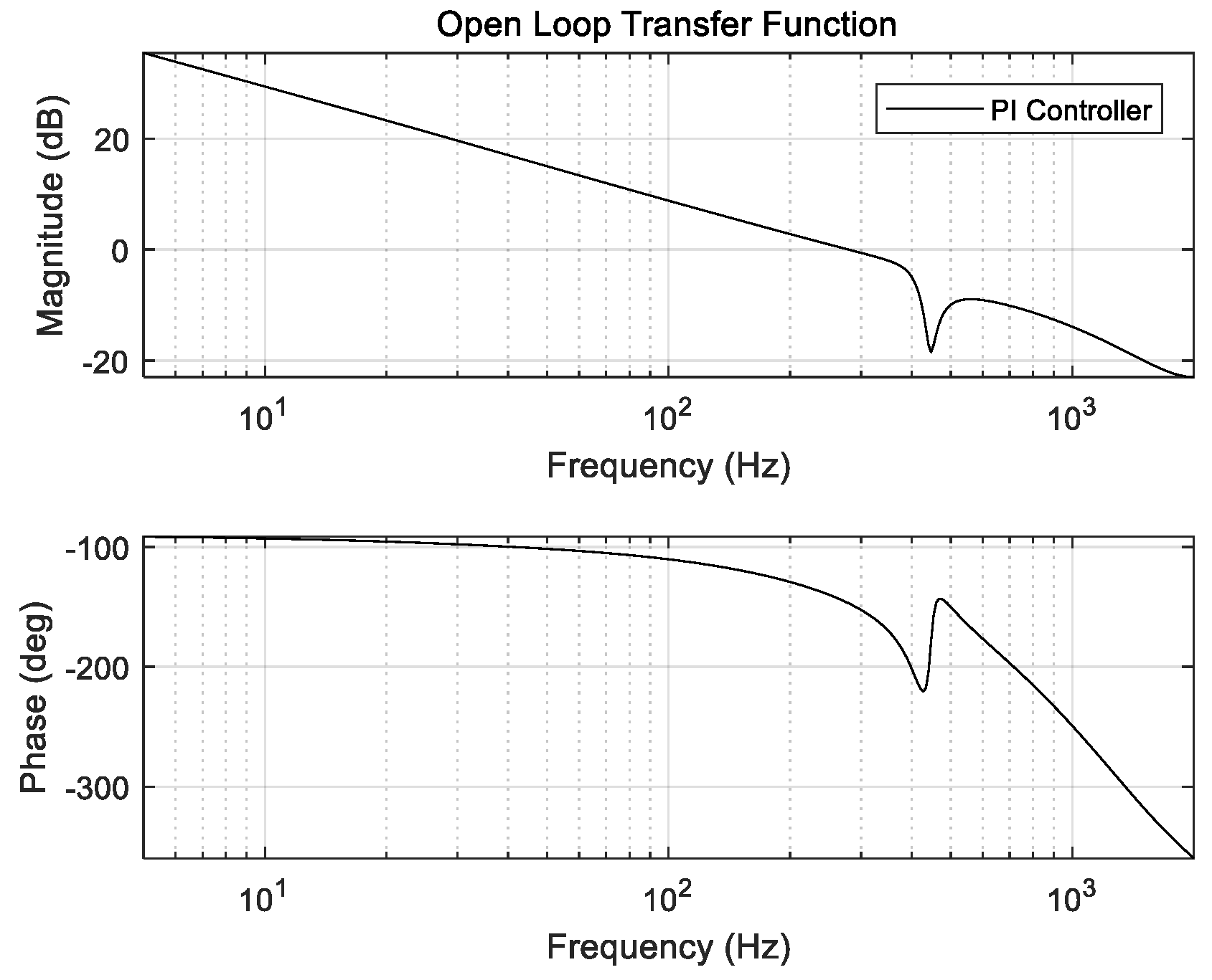
2.2. Tip-Tilt Controller of FSM Control System

PI controllers are commonly used in real control systems for the tip-tilt control of FSM control systems. The tip-tilt controller is designed to achieve the designed gain margin, phase margin, crossover frequency, and loop gain. Although it is feasible to obtain a wider crossover frequency, the crossover frequency is limited by the sampling frequency of the DSP, feedback sensor signal, and other components. The open-loop transfer function of the designed PI controller for FSM control systems is illustrated in Figure 3, where the PI controller, crossover frequency, gain margin, phase margin, and loop gain are 91.1 Hz, 11.8 dB, 68.7°, and >30 dB, respectively. Moreover, the disturbance-rejection performance of the designed PI controller for FSM control systems is depicted in Figure 4. The transfer function of the PI controller is expressed as follows [35]:
C s = K P + K I s = 0.5 + 900 s
where KP and KI are the proportional and integral gains, respectively, and their values are 0.5 and 900, as determined using Equation (3).

3. Anti-Shock Controller for FSM System

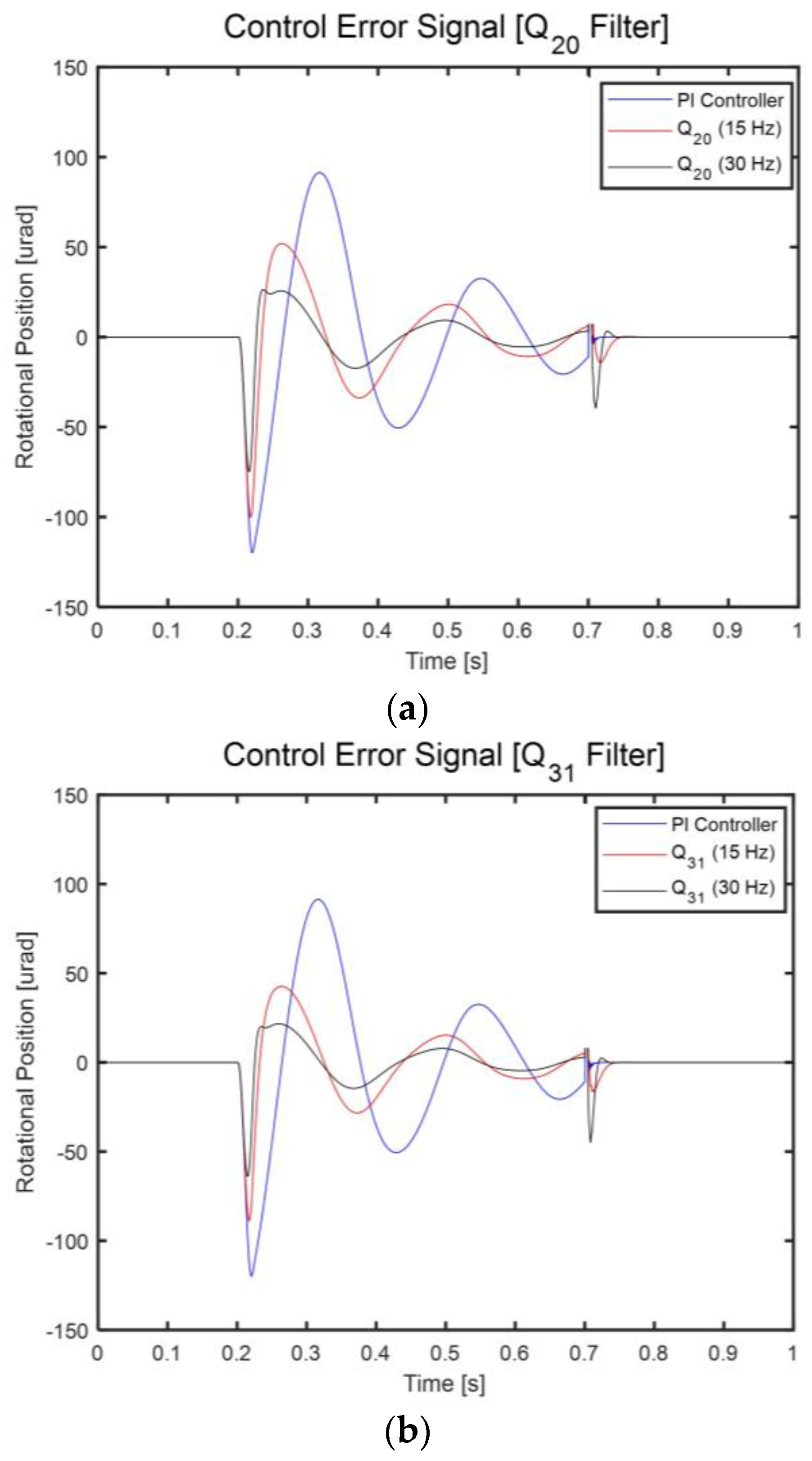
3.1. Shock Specifications

As illustrated in Figure 5, a shock is defined as a half-sine pulse with 5 g acceleration and a duration of 10 ms. Unlike periodic disturbances, shocks exhibit nonperiodic characteristics. The aforementioned shock is applied to the system in the vertical direction of the optical bench on the platform so that it interacts as a factor that hinders the tip-tilt control of the FSM system.

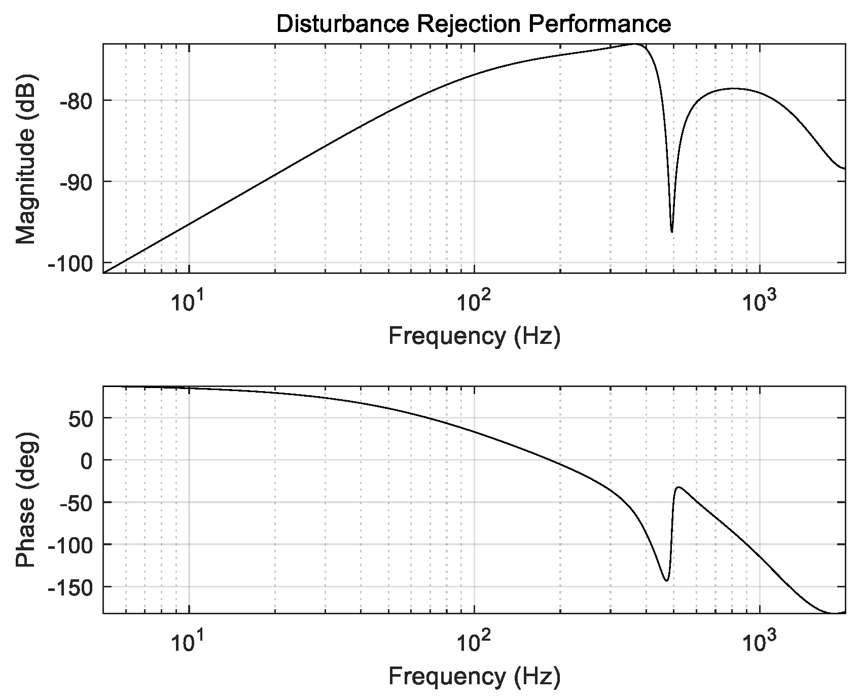
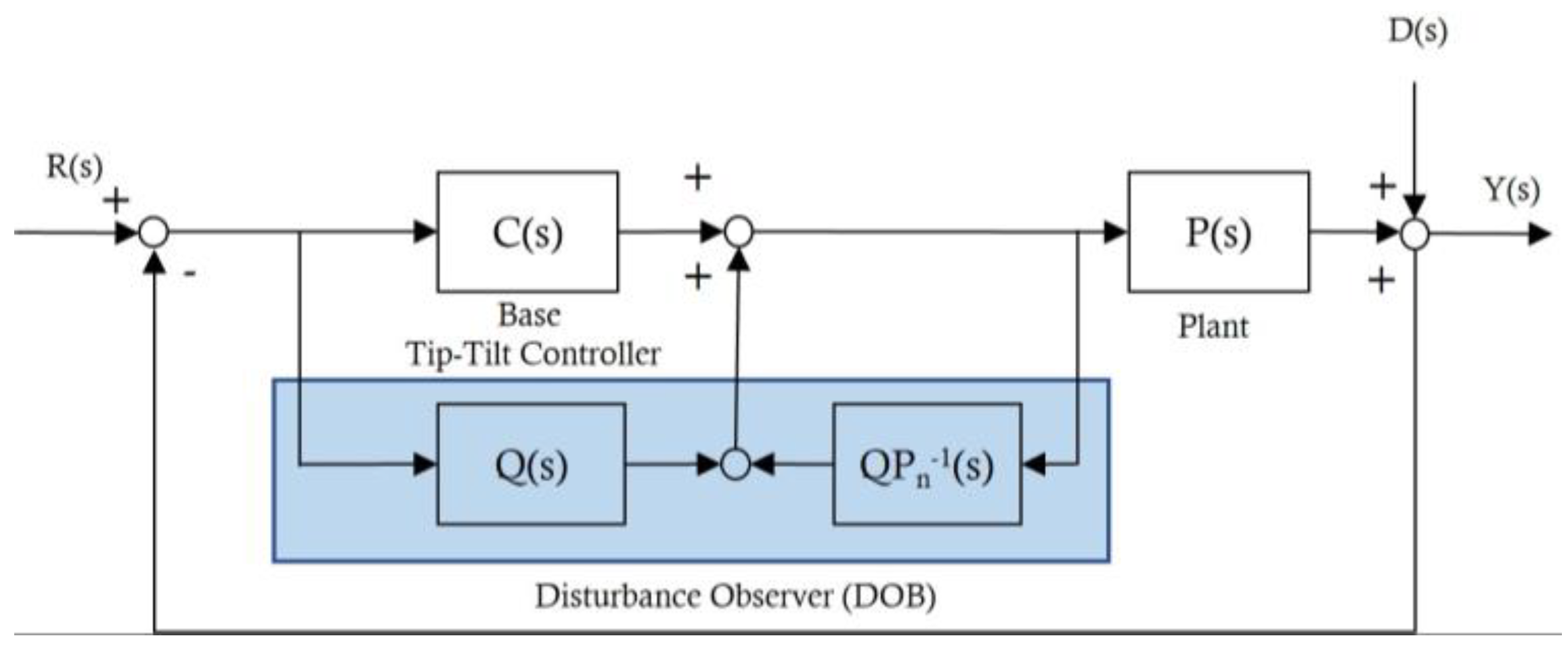
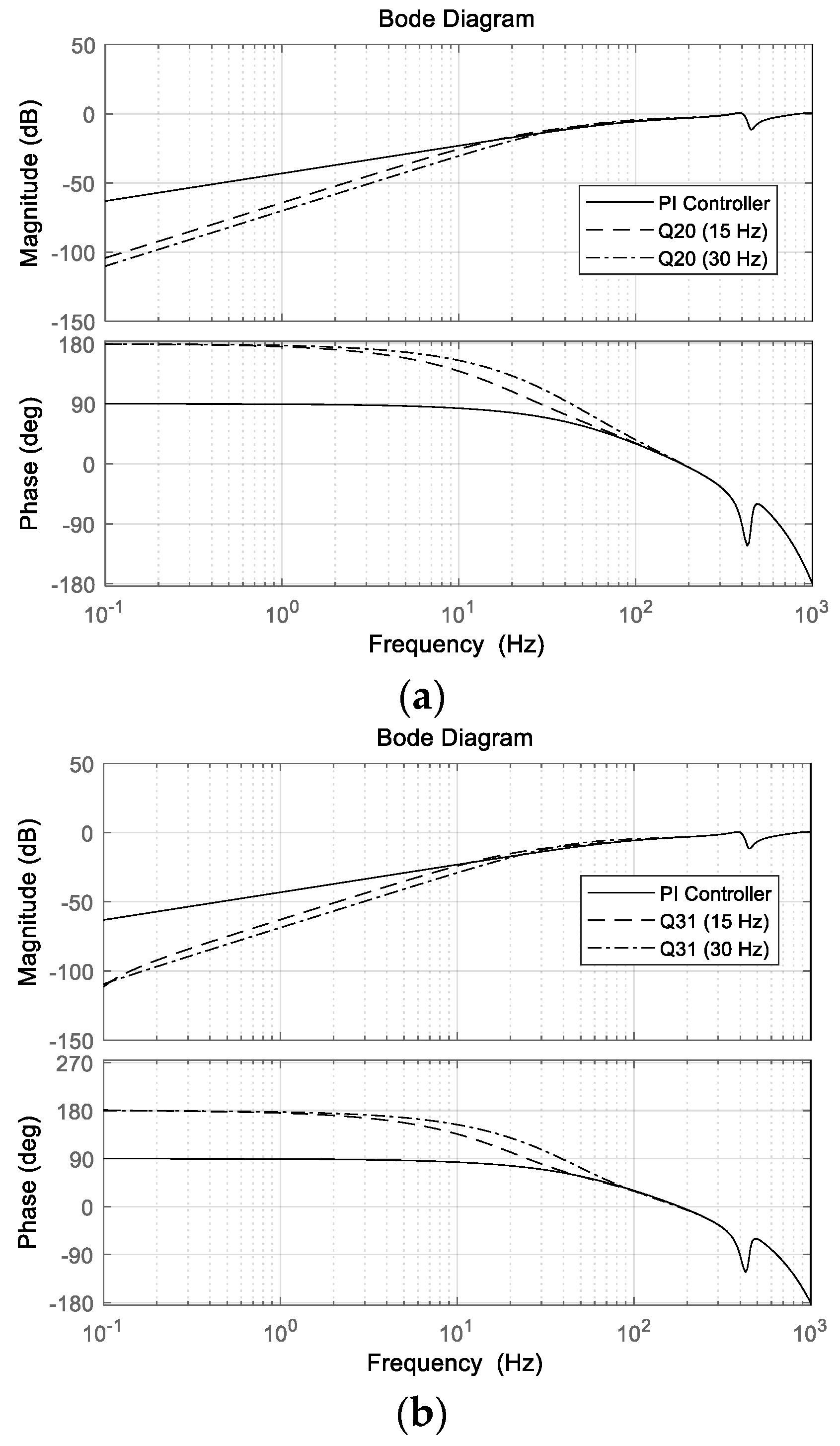
3.2. DOB-Based Anti-Shock Controller

The design of the DOB-based anti-shock controller, which aims to compensate for disturbances, is simple to implement because a DOB-based controller can be obtained simply by attaching a DOB to the original FSM control system. Theoretically, the DOB can be designed as an extended structure in the feedback control loop. The DOB-based controller rejects disturbances by injecting a compensation value into the control input; this compensation value is equal to the difference between the commanded control input to the plant and the plant output filtered by the inverse of the nominal plant Pn(s), i.e., Pn−1(s), as illustrated in Figure 6. However, because Pn−1(s) generally contains pure differential terms, it is not often physically realizable. Therefore, it is common to use a Q filter in conjunction with Pn−1(s). This Q filter typically has the characteristics of a low-pass filter (LPF) with a direct current (DC) gain of unity. In this study, a binomial Q filter is used as the LPF. The higher the filter order, the better the realized performance. A high-order filter could adversely affect the controller performance owing to phase lag. In addition, the bandwidth of the Q filter influences the system response. As the bandwidth of the Q filter increases, the speed of rejecting undesirable disturbances increases. Thus, the Q filter is important for securing the performance of the DOB. Figure 6 schematically illustrates the DOB-based anti-shock controller for FSM control systems. The Open-loop transfer function of a continuous system is expressed as follows [34]:
Q m n s = i = 1 n a m i τ s i τ s + 1 m ,
where τ is a time constant, ami denotes the binomial coefficients calculated as (m!/mi)! i!, m is the denominator order, and n is the numerator order (mn). Generally, the robustness of the DOB improves as the denominator order increases. For example, if a Q31 filter is used instead of a Q20 filter, the robustness of the DOB system will improve. In addition, control system stability shares a trade-off relationship with the bandwidth of the Q filter. Therefore, the bandwidth of the Q filter must be selected experimentally to maximize the stability of the control system. For this reason, this study uses the binomial Q20 and Q31 filters in the proposed DOB-based controller for FSM systems, as illustrated in Figure 7. This is because the stability of the control system can be estimated from the residual control error signal (CES), which is the experimental result. The use of Q20 and Q31 filters effectively improves the disturbance-suppression performances of the FSM control system. Moreover, the disturbance-suppression performances of the FSM control system are effective in the low-frequency region with bandwidths of 15 and 30 Hz. The Open-loop transfer functions of the aforementioned Q20 and Q31 filters with bandwidths of 15 and 30 Hz are expressed as follows [34]:
Q 20 s = 1 τ 2 s 2 + 2 τ s + 1 = 1 4.6 × 10 5 s 2 + 1.4 × 10 2 s + 1   [ 15   H z ]
Q 20 s = 1 τ 2 s 2 + 2 τ s + 1 = 1 1.2 × 10 5 s 2 + 6.8 × 10 3 s + 1   [ 30   H z ]
Q 31 s = 3 τ s + 1 τ 3 s 3 + 3 τ 2 s 2 + 3 τ s + 1 = 5.1 × 10 2 s + 1 4.9 × 10 6 s 3 + 8.7 × 10 4 s 2 + 5.1 × 10 2 s + 1 [ 15   H z ]
Q 31 s = 3 τ s + 1 τ 3 s 3 + 3 τ 2 s 2 + 3 τ s + 1 = 2.6 × 10 2 s + 1 6.1 × 10 7 s 3 + 2.2 × 10 4 s 2 + 2.6 × 10 2 s + 1 [ 30   H z ]
As mentioned previously, the loop gain of the control system should be high in the frequency domain of dynamic disturbances. Therefore, the loop gain of the DOB-based anti-shock controller for FSM control systems is greater than that of the PI controller for the base tip-tilt controller. Moreover, the control loop gain is improved by increasing the bandwidth of the Q filter. The Open-loop transfer function of the overall DOB-based anti-shock controller for FSM control systems is illustrated in Figure 8, and it is expressed as follows [36]:
G D O B ( s ) = C S P n + 1 ( 1 Q s ) ( 1 Q s ) P n ,
where Pn(s) is the nominal plant, and Q(s) is the binomial Q filter. The Open-loop transfer function and sensitivity transfer function of the overall FSM control system with the modified DOB are presented in Figure 5 and Figure 6, respectively.
As illustrated in Figure 8 and Figure 9, the disturbance-rejection performance of the DOB-based anti-shock controller for FSM control systems improves as the denominator order of the Q filter increases. Furthermore, for the same denominator order (m) of the Q filter, an increase in the Q filter bandwidth improves the disturbance-rejection performance. For example, in the case of the FSM control system, the Open-loop gain of the Q31 filter is superior to that of the Q20 filter between 0 Hz and 70 Hz. If the denominator order of the filter is the same, then the Q filter with a bandwidth of 30 Hz can improve the Open-loop gain of the FSM control system compared to that achieved using the Q filter with a bandwidth of 15 Hz.

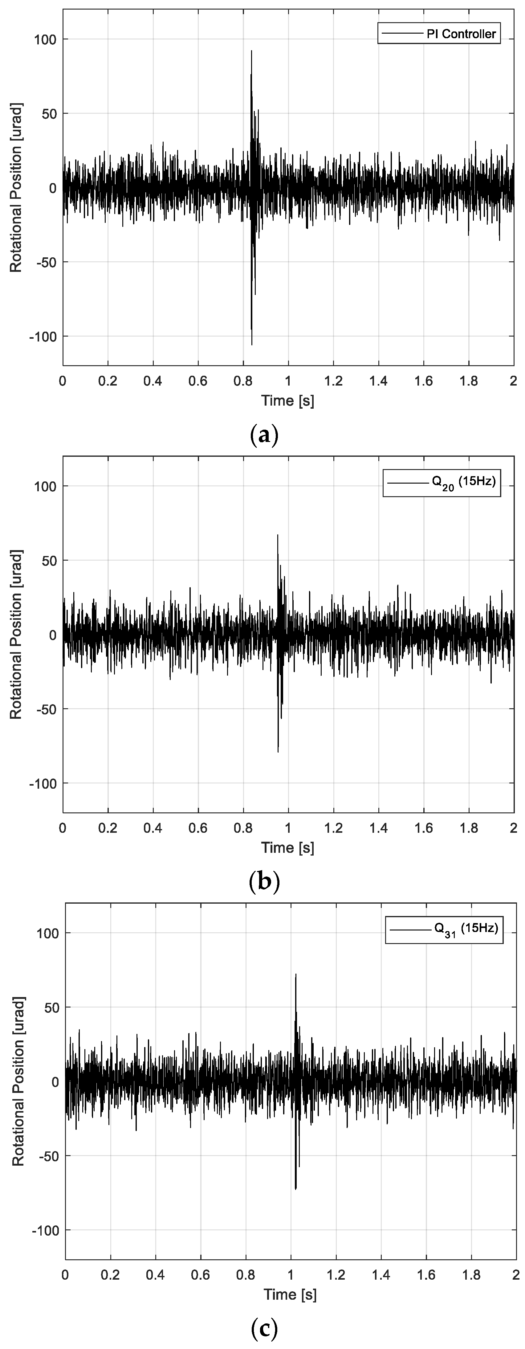
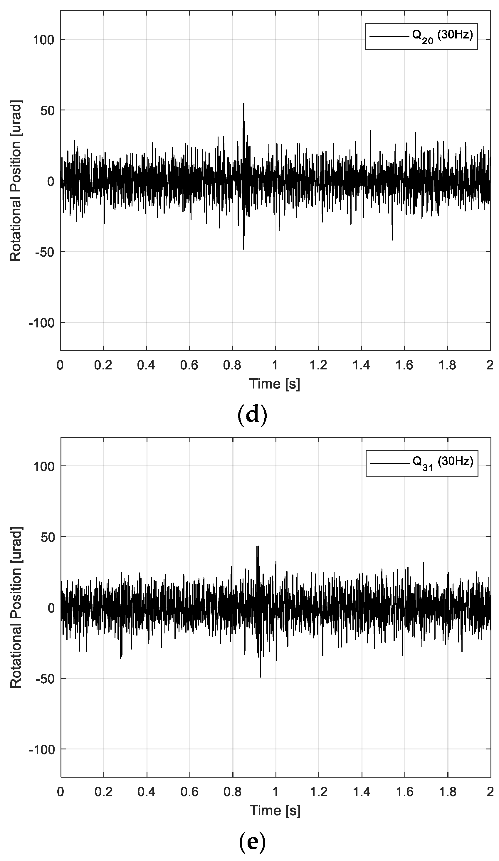
4. Performance of Anti-Shock Controller for FSM System

The simulated performance results of the DOB-based anti-shock controller for FSM control systems revealed that the target rotational position was maintained successfully at 0 μrad (i.e., neutral rotational position). When the 15 Hz bandwidth Q20 and Q31 filters were used in the DOB-based FSM control system, the RMS CES values were 100.1 and 88.8 μrad, respectively. Furthermore, when the 30 Hz bandwidth Q20 and Q31 filters were used in the DOB-based FSM control system, the RMS CES values were 74.9 and 63.9 μrad, respectively, as illustrated in Figure 10a,b. The overall simulated performance results of the DOB-based anti-shock controller for FSM control systems are summarized in Table 2.
The experimental performance results are presented in Figure 11. The experimental performance results of the DOB-based anti-shock controller for FSM control systems revealed that the target rotational position was maintained successfully at 0 μrad (i.e., neutral rotational position). According to Figure 11a, the root mean square (RMS) residual CES of the PI controller was 9.9 μrad. When the 15 Hz bandwidth Q20 and Q31 filters were used in the DOB-based FSM control system, the RMS CES values were 100.1 and 88.8 μrad, respectively, as illustrated in Figure 11b,c. Furthermore, when the 30 Hz bandwidth Q20 and Q31 filters were used in the DOB-based FSM control system, the RMS CES values were 74.9 and 63.9 μrad, respectively, as illustrated in Figure 11d,e.
Eventually, the disturbance-rejection performance in the DOB-based anti-shock controller for FSM systems improved as the order of the denominator and numerator increased, and as the bandwidth of the Q filter increased. The overall performance results of the DOB-based anti-shock controller for FSM control systems are summarized in Table 3. These results indicate that the performance of the proposed anti-shock controller was superior to that of the controller reported in previous studies [37,38].

5. Conclusions

In this study, we investigated how to improve the disturbance-rejection performance of an anti-shock controller for FSM systems by using a DOB to improve its tip-tilt control performance under external shocks. First of all, we analyzed the robustness of the DOB system quantitatively through the simulated performance of the DOB system. Also, the design parameters of the DOB system were experimentally derived.
Eventually, when the 15 Hz bandwidth Q20 filter was used in the DOB-based anti-shock controller for FSM systems, the CES value decreased by 25.3% compared to that in the case without the DOB. Furthermore, when the 15 Hz bandwidth Q31 filter was used in the DOB-based anti-shock controller for FSM systems, the CES value decreased by 31.9% compared to that in the case without the DOB. Furthermore, to improve the disturbance-rejection performance of the DOB-based anti-shock controller for FSM systems, the bandwidth of the Q20 and Q31 filters used therein was set to 30 Hz. The CES value decreased by approximately 48.4% and 59.1% when using the Q20 and Q31 filters, respectively, compared to that in the absence of the DOB.
These results indicate that the disturbance-rejection performance of the DOB-based control system improves as the order of the denominator and numerator of the Q filter increases, and as the bandwidth of the Q filter increases. Consequently, the proposed anti-shock controller performed efficiently in suppressing external disturbances in the FSM system.

Funding

This work was supported by an Agency for Defense Development (ADD) grant funded by the Government of the Republic of Korea in 2024.

Data Availability Statement

Data is contained within the article.

Conflicts of Interest

The author declares no conflicts of interest.

References

  1. Sun, C.; Ding, Y.; Wang, D.; Tian, D. Backscanning step and stare imaging system with high frame rate and wide coverage. App. Opt. 2015, 54, 4960–4965. [Google Scholar] [CrossRef] [PubMed]
  2. Liu, W.; Yao, K.; Huang, D.; Lin, X.; Wang, L.; Lv, Y. Performance evaluation of coherent free space optical communications with a double-stage fast-steering-mirror adaptive optics system depending on the Greenwood frequency. Opt. Exp. 2016, 24, 13288–13302. [Google Scholar] [CrossRef]
  3. Mokbel, H.F.; Yuan, W.; Ying, L.Q.; Hua, C.G.; Roshdy, A. Research on the mechanical design of two-axis fast steering mirror for optical beam guidance. In Proceedings of the 1st International Conference on Mechanical Engineering and Material Science (MEMS 2012), Shanghai, China, 28–30 December 2012; pp. 205–209. [Google Scholar]
  4. Ye, D.; Li, S.; Yan, Z.; Zhang, Z.; Liu, Y. A new method for incoherent combining of far-field laser beams based on multiple faculae recognition. In Young Scientists Forum; SPIE: Bellingham, WA, USA, 2017; Volume 10710, p. 1071034. [Google Scholar]
  5. Merritt, P.H.; Albertine, J.R. Beam control for high-energy laser devices. Opt. Eng. 2013, 52, 021005. [Google Scholar] [CrossRef]
  6. Perram, G.P.; Marciniak, M.A.; Goda, M. High-energy laser weapons: Technology overview. Laser Technol. Def. Secur. 2004, 5414, 1–25. [Google Scholar]
  7. Meline, M.E.; Harrell, J.P.; Lohnes, K.A. Universal beam steering mirror design using the cross blade flexure. In Acquisition, Tracking, and Pointing VI; SPIE: Bellingham, WA, USA, 1992; Volume 1697, pp. 424–443. [Google Scholar]
  8. Dong, W.; Tang, J.; ElDeeb, Y. Design of dual-stage actuation system for high precision optical manufacturing. In Active and Passive Smart Structures and Integrated Systems; SPIE: Bellingham, WA, USA, 2008; Volume 6928, p. 692828. [Google Scholar]
  9. Schellekens, P.; Rosielle, N.; Vermeulen, H.; Vermeulen, M.M.P.A.; Wetzels, S.F.C.L.; Pril, W. Design for precision: Current status and trends. CIRP Ann. 1998, 47, 557–586. [Google Scholar] [CrossRef]
  10. Kluk, D.J.; Boulet, M.T.; Trumper, D.L. A high-bandwidth, High-precision, two-axis steering mirror with moving iron actuator. Mechatronics 2012, 22, 257–270. [Google Scholar] [CrossRef]
  11. Li, D.; Wu, T.; Ji, Y.; Li, X. Model analysis and resonance suppression of wide-bandwidth inertial reference system. Nanotechnol. Precis. Eng. 2019, 2, 177–187. [Google Scholar] [CrossRef]
  12. Gu, G.Y.; Zhu, L.M.; Su, C.Y.; Ding, H.; Fatikow, S. Modeling and control of piezo-actuated nanopositioning stages: A survey. IEEE Trans. Auto. Sci. Eng. 2016, 13, 313–332. [Google Scholar] [CrossRef]
  13. Ling, J.; Feng, Z.; Ming, M.; Xiao, X. Damping controller design for nanopositioners: A hybrid reference model matching and virtual reference feedback tuning approach. Int. J. Precis. Eng. Manuf. 2018, 19, 13–22. [Google Scholar] [CrossRef]
  14. Gu, G.Y.; Zhu, L.M.; Su, C.Y. Integral resonant damping for high-bandwidth control of piezoceramic stack actuators with asymmetric hysteresis nonlinearity. Mechatronics 2014, 24, 367–375. [Google Scholar] [CrossRef]
  15. McEver, M.A.; Cole, D.G.; Clark, R.L. Adaptive feedback control of optical jitter using Q-parameterization. Opt. Eng. 2004, 43, 904–910. [Google Scholar] [CrossRef]
  16. Arancibia, N.O.P.; Chen, N.; Gibson, S.; Tsao, T.C. Adaptive control of a MEMS steering mirror for free-space laser communications. In Free—Space Laser Communications V; SPIE: Bellingham, WA, USA, 2005; Volume 5892, p. 589210. [Google Scholar]
  17. Wang, G.; Chen, G.; Bai, F. High-speed and precision control of a piezoelectric positioner with hysteresis, resonance and disturbance compensation. Microsyst. Technol. 2016, 22, 2499–2509. [Google Scholar] [CrossRef]
  18. Schitter, G.; Thurner, P.J.; Hansma, P.K. Design and input-shaping control of a novel scanner for high-speed atomic force microscopy. Mechatronics 2008, 18, 282–288. [Google Scholar] [CrossRef]
  19. Odgaard, P.F.; Stoustrup, J.; Andersen, P.; Wickerhauser, M.V.; Mikkelsen, H.F. A simulation model of focus and radial servos in compact disc players with disc surface defects. In Proceedings of the 2004 IEEE International Conference on Control Applications, Taipei, Taiwan, 2–4 September 2004; pp. 105–110. [Google Scholar]
  20. Hilkert, J.M. A comparison of inertial line-of-sight stabilization techniques using mirrors. In Acquisition, Tracking, and Pointing XVIII; SPIE: Bellingham, WA, USA, 2004; Volume 5430, p. 13. [Google Scholar]
  21. Zhou, Y.; Steinbuch, M. Estimator-based sliding mode control of an optical disc drive under shock and vibration. In Proceedings of the International Conference on Control Applications, Glasgow, UK, 18–20 September 2002; pp. 631–636. [Google Scholar]
  22. Gu, G.Y.; Zhu, L.M. Motion control of piezoceramic actuators with creep, hysteresis and vibration compensation. Sens. Actuators A Phys. 2013, 197, 76–87. [Google Scholar] [CrossRef]
  23. Böhm, M.; Pott, J.U.; Kürster, M.; Sawodny, O.; Defrere, D.; Hinz, P. Delay compensation for real time disturbance estimation at extremely large telescopes. IEEE Trans. Control Syst. Technol. 2016, 25, 1384–1393. [Google Scholar] [CrossRef]
  24. Glück, M.; Pott, J.U.; Sawodny, O. Piezo-actuated vibration disturbance mirror for investigating accelerometer-based tip-tilt reconstruction in large telescopes. IFAC Papersonline 2016, 49, 361–366. [Google Scholar] [CrossRef]
  25. Nakao, M.; Ohnishi, K.; Miyachi, K.A. Robust decentralized joint control based on interference estimation. In Proceedings of the 1987 IEEE International Conference on Robotics and Automation, Raleigh, NC, USA, 31 March–3 April 1987; pp. 326–331. [Google Scholar]
  26. Ohishi, K.; Ohde, H. Collision and force control for robot manipulator without force sensor. In Proceedings of the IECON’94—20th Annual Conference of IEEE Industrial Electronics, Bologna, Italy, 5–9 September 1994; Volume 2, pp. 766–771. [Google Scholar]
  27. Kim, B.K.; Chung, W.K.; Youm, Y. Robust learning control for robot manipulators based on disturbance observer. In Proceedings of the 1996 IEEE IECON. 22nd International Conference on Industrial Electronics, Control, and Instrumentation, Taipei, Taiwan, 9 August 1996; pp. 1276–1282. [Google Scholar]
  28. Wang, L.; Su, J.; Xiang, G. Robust motion control system design with scheduled disturbance observer. IEEE Trans. Ind. Electron. 2016, 63, 6519–6529. [Google Scholar] [CrossRef]
  29. Chen, W.H.; Yang, J.; Guo, L.; Li, S. Disturbance-observer-based control and related methods—An overview. IEEE Trans. Ind. Electron. 2016, 63, 1083–1095. [Google Scholar] [CrossRef]
  30. Tang, T.; Ma, J.; Ge, R. PID-I controller of charge coupled device-based tracking loop for Fast-steering mirror. Opt. Eng. 2011, 50, 043002. [Google Scholar] [CrossRef]
  31. Lee, H.S.; Tomizuka, M. Robust motion controller design for high-accuracy positioning systems. IEEE/ASME Trans. Mechatron. 2000, 2, 32–38. [Google Scholar]
  32. White, M.; Tomizuka, M.; Smith, C. Improved track following in magnetic disk drives using a disturbance observer. IEEE/ASME Trans. Mechatron. 2000, 5, 3–11. [Google Scholar] [CrossRef]
  33. Norman, S.N. Control System Engineering, 3rd ed.; Wiley: New York, NY, USA, 2008; pp. 49–52. [Google Scholar]
  34. Li, X.; Chen, S.L.; Teo, C.S.; Tan, K.K. An iterative data-based approach to disturbance observer sensitivity shaping. In Proceedings of the IECON 2016—42nd Annual Conference of the IEEE Industrial Electronics Society, Florence, Italy, 24–27 October 2016; pp. 6067–6072. [Google Scholar]
  35. Chen, G.; Liu, P.; Ding, H. Structural parameter design method for a Fast-steering mirror based on a closed-loop bandwidth. Front. Mech. Eng. 2019, 15, 55–65. [Google Scholar] [CrossRef]
  36. Deng, J.; Ren, W.; Zhang, H.; Luo, Y.; Zhou, X.; Mao, Y. A modified observer structure based on acceleration measurement for disturbance suppression in tracking control system. App. Sci. 2018, 8, 1571. [Google Scholar] [CrossRef]
  37. Nam, B.U.; Gimm, H.; Kang, D.; Gweon, D. Design and analysis of a tip-tilt guide mechanism for the fast steering of a large-scale mirror. Opt. Eng. 2016, 55, 106120. [Google Scholar] [CrossRef]
  38. Nam, B.U.; Gimm, H.; Kim, J.G.; Kim, G.T.; Kim, B.U. Development of a fast steering mirror of large diameter. In Integrated Photonics: Materials, Devices, and Applications IV; SPIE: Bellingham, WA, USA, 2017; Volume 10249, p. 102490R. [Google Scholar]
Figure 1. Frequency response and linear transfer function of real plant.
Applsci 14 04774 g001
Figure 2. (a) FSM control system; (b) tip-tilt actuating platform (PI Ceramic GmbH); and (c) Scalexio AutoBox (dSPACE).
Applsci 14 04774 g002
Figure 3. Open-loop transfer function of PI controller in FSM control system.
Applsci 14 04774 g003
Figure 4. Disturbance-rejection performance of PI controller in FSM control system.
Applsci 14 04774 g004
Figure 5. Specifications of external shock.
Applsci 14 04774 g005
Figure 6. Schematic diagram of DOB-based anti-shock controller for FSM control systems.
Applsci 14 04774 g006
Figure 7. Open-loop transfer function of Q filters used in DOB-based anti-shock controller for FSM control systems: (a) Q20 and (b) Q31 filters.
Applsci 14 04774 g007aApplsci 14 04774 g007b
Figure 8. Open-loop transfer function of DOB-based anti-shock controller for FSM control systems: (a) Q20 and (b) Q31 filters.
Applsci 14 04774 g008
Figure 9. Disturbance-rejection performance of DOB-based anti-shock controller for FSM control systems: (a) Q20 and (b) Q31 filters.
Applsci 14 04774 g009
Figure 10. Simulated performance results obtained using DOB-based anti-shock controller for FSM control systems: (a) Q20 filter (15/30 Hz), and (b) Q31 filter (15/30 Hz).
Applsci 14 04774 g010
Figure 11. Performance results obtained using DOB-based anti-shock controller for FSM control systems: (a) PI controller, (b) Q20 filter (15 Hz), (c) Q31 filter (15 Hz), (d) Q20 filter (30 Hz), and (e) Q31 filter (30 Hz).
Applsci 14 04774 g011aApplsci 14 04774 g011b
Table 1. Dynamic characteristics of real plant.
SpecificationValue
Resonance frequency450.2 Hz
5 Hz sensitivity168.3 µrad/V
Gain of voltage amplifier10 V/V
Gain of sensor amplifier0.0059 V/µrad
Table 2. Simulated performance results obtained using DOB-based anti-shock controller for FSM control systems.
SpecificationPI ControllerQ20 FilterQ31 Filter
15 Hz30 Hz15 Hz30 Hz
Minimum rotational position error (rms)119.9 μrad100.1 μrad74.9 μrad88.8 μrad63.9 μrad
Reduced rate-16.5%37.6%25.9%46.7%
Table 3. Experimental performance results obtained using DOB-based anti-shock controller for FSM control systems.
SpecificationPI ControllerQ20 FilterQ31 Filter
15 Hz30 Hz15 Hz30 Hz
Minimum rotational position error (rms)106.0 μrad79.1 μrad54.7 μrad72.2 μrad43.4 μrad
Reduced rate-25.3%48.4%31.9%59.1%
Disclaimer/Publisher’s Note: The statements, opinions and data contained in all publications are solely those of the individual author(s) and contributor(s) and not of MDPI and/or the editor(s). MDPI and/or the editor(s) disclaim responsibility for any injury to people or property resulting from any ideas, methods, instructions or products referred to in the content.

