Article

Dynamic Balance Simulation and Optimization of Electric Vehicle Scroll Compressor Rotor System

School of Automotive & Rail Transit, Nanjing Institute of Technology, Nanjing 211167, China
*
Authors to whom correspondence should be addressed.
Appl. Sci. 2024, 14(12), 5024; https://doi.org/10.3390/app14125024
Submission received: 6 May 2024 / Revised: 4 June 2024 / Accepted: 7 June 2024 / Published: 9 June 2024

Abstract

:
In order to solve the problem of imbalance of internal forces in the system caused by the gravity force of the eccentric wheel and the orbiting scroll close to the drive bearing and the rotational inertia force during the operation of the electric scroll compressor, a dynamic model of the rotor system of the scroll compressor that takes into account the effect of the gas force was established using the multibody dynamics software ADAMS/View 2020. Dynamic simulation analysis of the rotor system is carried out, focusing on the force of the drive bearing; a parametric optimization method is adopted to optimize the position of the center-of-mass coordinates of the eccentric wheel of the relevant components, and the relevant parameters are derived after optimization. The results show that by adjusting the center-of-mass position of the eccentric wheel it is possible to optimize the unbalance force and unbalance moment of the main shaft drive system; compared with the pre-optimization, the force fluctuation ranges of the drive bearing in the horizontal and vertical directions are reduced, the peak value is reduced by 18%, and the impact force of the drive bearing during the initial period of compressor operation is effectively relieved. Through optimization calculation, the vibration and noise of the system are reduced, the operating stability of the scroll compressor is improved, and analytical methods and theoretical guidance are provided for the design and prediction of the dynamic behavior of the scroll compressors.

1. Introduction

As an important piece of equipment in the fields of power engineering, transportation and air conditioning refrigeration, scroll compressors are facing increasingly important mechanical challenges in their rotor systems [1,2]. Especially during operation, the moment of overturning and the gas force of the orbiting scroll plate have complex dynamic effects on the driving bearing. In order to meet these challenges, it is necessary to balance the centrifugal force of the rotor by evenly distributing the rotor’s mass, thereby reducing vibration. This process is called dynamic balancing of the rotor system, and dynamic balancing is one of the key factors to ensure the stability and reliability of the rotor when rotating at high speed.
Engineering practice shows that the life of drive bearings in scroll compressors is often much lower than that of other bearing types in the system, which not only poses a threat to the normal operation of scroll compressors but also has an important impact on compressor life tests. By gaining a deep understanding of the mechanical characteristics of the drive bearing, the efficient and reliable operation of the scroll compressor can be effectively ensured, thus enhancing its performance level and service life. This is also important for the overall performance and sustainability of electric vehicles. Efficient scroll compressors can significantly reduce energy consumption, increase the range of electric vehicles, and reduce the load on the cooling system, thus improving the operating efficiency of electric motors and batteries. Longer service life means less maintenance and less frequent replacement, which reduces resource consumption and waste generation. In summary, dynamic balance optimization of the rotor system not only improves the performance and reliability of scroll compressors but also makes electric vehicles more efficient, economical and environmentally friendly.
In recent years, there have been substantial studies on the scroll compressor rotor system and its drive bearing. Zhang et al. [3] provide an overview of the current applications and research status of electric scroll compressors, including the optimal design of scroll compressor profiles, rolling disk leakage seals and computer simulation optimization design methods. In addition, trends in the development of steam injection scroll compressors are discussed, as well as recent research progress and sustainable applications of new refrigerant CO2 in electric scroll compressors. Finally, recommendations for the application of electric scroll compressors are summarized, and directions for future research are proposed. Li et al. [4], for example, conducted a detailed analysis on the scroll compressor rotor system’s crankshaft displacement, drive-bearing speed and acceleration, gap contact force, and other parameters, elucidating the law of their variation over time and their relationships with gap size. In another study, Dang et al. [5] employed both theoretical analysis and numerical simulation to study the power characteristics of the flexible mechanism of the scroll compressor rotor systems, shedding light on the role of the dynamic scroll disk in the radial flexible mechanism and the law of rotor vibration to enhance the performance and reliability of the system. Zhao et al. [6,7] delved into the effects of radial load, overturning moment, and bearing radial clearance on the mechanical characteristics of needle roller bearings, using the scroll compressor as the research object to provide optimization suggestions for its structural design. Li et al. [8,9] further analyzed the influence of moving parts clearance on the operating characteristics of the scroll compressor drive system using the nonlinear spring damping and Coulomb friction model. They found that increasing the gap would lead to an increase in key rotor system parameters (e.g., displacement, velocity, acceleration), a decrease in frequency fluctuation, and at the same time would trigger problems such as stress concentration, which would lower the rotor system’s critical speed and increase the risk of resonance. Li [10] conducted a detailed analysis of the structure of the rotor components of the new energy scroll compressor and its dynamic balance, including the composition of the components, the computation of inertial force and inertial moment, and the dynamic simulation and analysis of the rotor components and their dynamic balance based on the ADAMS/View 2020 for dynamic simulation analysis and the effect of different variables (e.g., eccentric wheel mass, balancing block design, etc.) on the unbalanced forces and moments in the shaft system, ultimately reducing the unbalanced forces and moments through the optimization of the design. Tiwari et al. [11] investigated the nonlinear dynamic response of the horizontal rigid rotor with imbalance supported by the ball bearings, observing nonlinear effects due to the increase in the radial internal clearance. Wang et al. [12] studied the dynamic balance problem of a single disk and single-span rotor-bearing system and proposed a new measurement point vector method based on an analytical approach, which is capable of identifying rotor unbalance under steady-state operating conditions and provides an effective method for efficient balance of rotor systems. Yu et al. [13] utilized the characteristics of the crankshaft bearings to enhance the dynamic performance of the scroll compressor. The optimal rack force is analyzed by adjusting the counterweight mounting angle, based on the force and moment equilibrium equations between the crankshaft and the compressor frame, with rack force and crankshaft-bearing load as variables. By controlling the design parameters of the crankshaft bearings to ensure bearing life and effectively managing the crankshaft-bearing load, the operational reliability of the scroll compressor is improved, and its service life is extended.
This study examines the rotor system of the scroll compressor from the perspective of vibration, balance, and shaft-bearing force, together with establishing a mathematical model to simulate the force interactions of the orbiting rotor and bearing and presents a case where simulation data can be accurately used to obtain the kinematic characteristics of the drive-bearing center of mass and the drive-shaft force. This study further employs the parameter optimization method to optimize the parameters of the related components, thus significantly reducing the force fluctuation of the driving bearing. The results and theories of this study can provide crucial guidance for optimizing the design of scroll-compressor-related components and enhancing the overall performance of the machine.

2. Dynamic Balance Principle of Rotor System

There are two main factors that cause the dynamic imbalance of the rotor system of the scroll compressor. On the one hand, there is the effect of gas forces on the compression chamber of the vortex disk. During the operation of the scroll compressor, the rotating and stationary scroll discs are subjected to the same gas force. Since the stationary scroll and compressor housing are directly connected together, the pneumatic force acting on the orbiting and stationary scroll will inevitably cause the vibration and noise of the scroll compressor to increase. On the other hand, the centrifugal force is caused by the eccentric structure of the rotor system. The scroll compressor belongs to the high-speed rotary machinery, and the main shaft of the rotor system is eccentric due to the working characteristics of the scroll compressor. In addition, according to the need for involute meshing of the scroll disk, the orbiting scroll does not rotate around the center of the stationary scroll, but rather moves in a flat motion around the stationary scroll in a metric rotation under the constraints of the anti-rotation mechanism, which results in the radius of rotation of the center of mass of the orbiting scroll disk relative to the center of the spindle to vary with the rotation angle of the spindle. Therefore, during the operation of the rotor system, the centrifugal force generated by the unbalanced mass acting on the eccentric spindle will result in an unbalanced spindle motion.
For the above reasons, two balancing methods are adopted: one balancing in order to determine the basic parameters of the balancing block, but due to the influence of the eccentric structure, the rotor system still retains a certain value of centrifugal force; the second balancing adopts a parametric optimization simulation of ADAMS/View 2020 to solve the problem of excessive change in the centrifugal force cycle. According to the principle of vibration, the transmission system of the scroll compressor belongs to periodic forced vibration, that is, the vibration generated by the system under periodic continuous excitation. For the transmission system of the scroll compressor, the source of periodic excitation is mainly the centrifugal force caused by the deviation of the center of mass of the transmission system from the main axis. The eccentric structure principle is shown in Figure 1.

3. Force Model

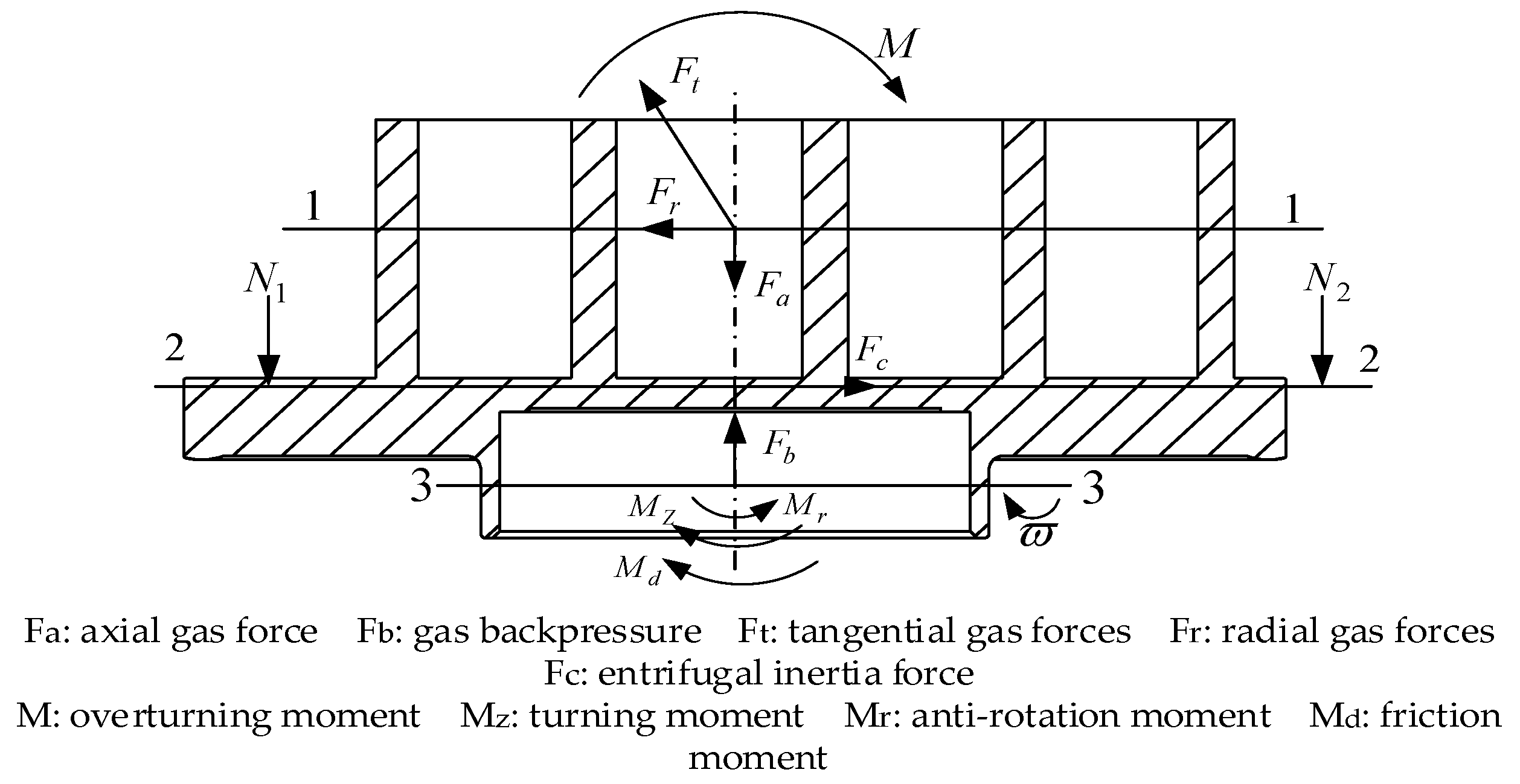
3.1. Force Model of Orbiting Scroll

The forces and moments affecting the orbiting scroll are depicted in Figure 2. During the operation phase, the contact force between the orbiting and stationary scroll, designated 1-1, is a key factor. The tangential and radial gas forces acting on the surface, represented by 2-2, also significantly affect the disc dynamics, as does the centrifugal inertia force acting on the surface, indicated by 3-3. The acting surface of the ball bearing, due to its non-overlapping nature with other forces, will generate tilting moments, leading to the tilt of the vortex disc [14,15].

3.2. Force Model of Drive Bearing

During the operation of a scroll compressor, the force model of the drive bearing in the rotor system is shown in Figure 3.
Its total radial force and moment of overturning are as follows:
F = F t 2 + ( F c c F r ) 2
M = F h ,
where F is the total radial force, F t is the tangential gas force, F r is the radial gas force, F c c is the equivalent effect of the centrifugal inertial force of the moving vortex disk transformed to the 1-1 working surface and h (mm) is the distance from the 1-1 working surface to the 3-3 working surface. The included angles of the line of action of the total radial force with respect to the y direction of the principal coordinates and the direction of the radial gas force are η (rad) and γ (rad), respectively. In the rotor system of the scroll compressor, the values of axial gas force F a , radial gas force F r and tangential gas force F t are constant, but the direction of action of the three forces is uncertain, and they all change with the change in the rotation angle of the main shaft.

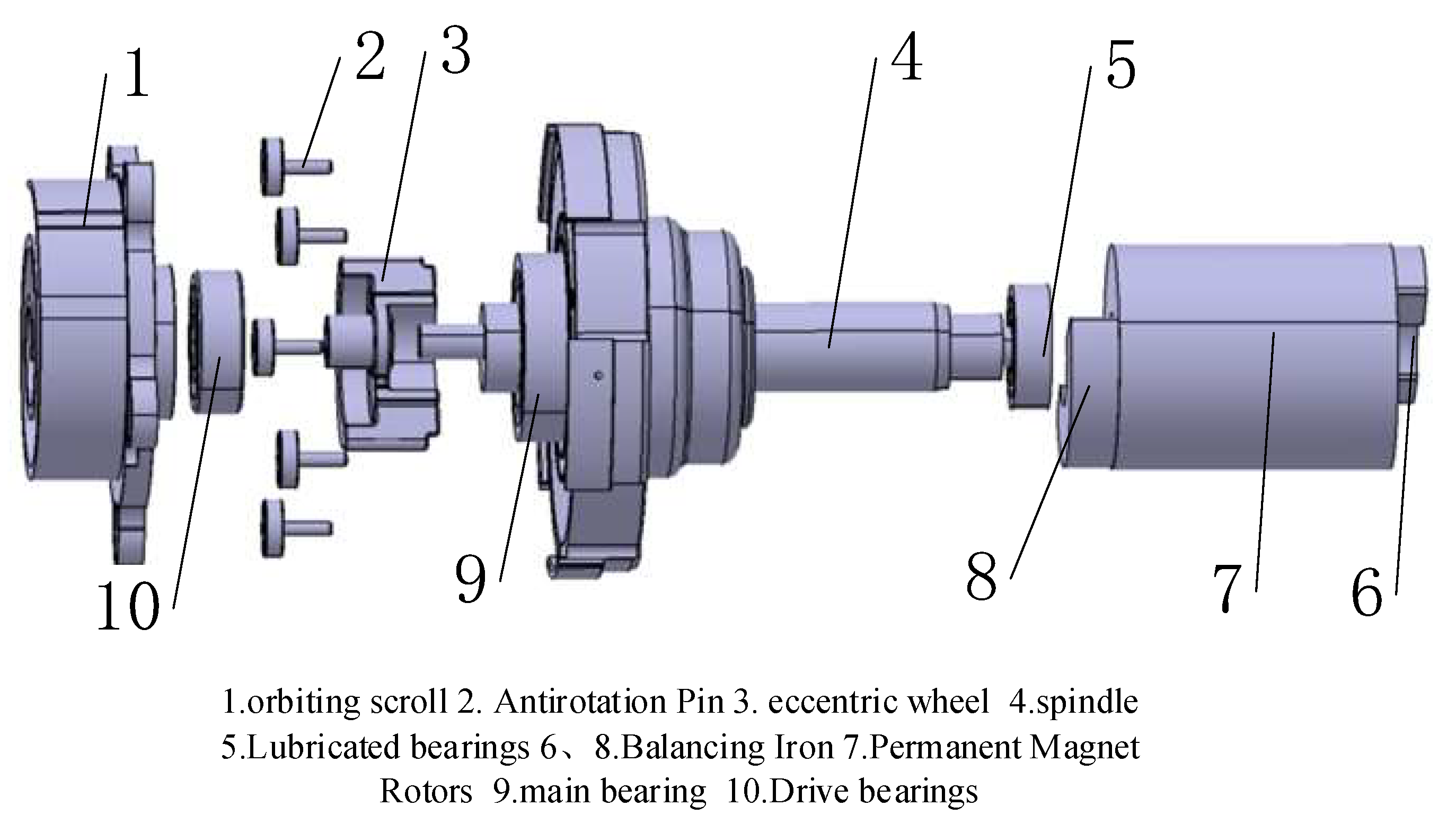
4. Scroll Compressor Rotor System Model

This paper presents a three-dimensional model of the rotor system of an electric scroll compressor, which consists of the crankshaft, balancing blocks, main and auxiliary bearings, motor rotor, cross-slip ring, eccentric wheel, drive bearing, and orbiting scroll [16,17]. Here, the orbiting scroll is connected to the eccentric wheel, which is then mounted on the eccentric crankshaft. The purpose of these devices is to change the static circular motion of the orbiting scroll plate to allow suction, exhaust and compression processes. Balancing blocks are installed at both ends of the motor rotor in a specific misaligned manner to balance the rotor system [18]. During the operation of the scroll compressor, the motor rotor drives the main shaft rotation, while the orbiting scroll in the cross-slip ring is constrained relative to the static vortex disk for rotational translation, thereby changing the volume of the vortex compression chamber. The assembly relationship of each component is verified through virtual assembly and interference checking. The structure explosion diagram is shown in Figure 4.

4.1. Defining Material Properties

First, the saved model is imported into the ADAMS/View 2020 in x_t file format, the size of each component of the scroll compressor rotor system determines the size of the setting time step, and the gravitational acceleration is 9.8 m/s2. After the initial import, the rotor system underwent further processing, including renaming the components and their respective colors, materials and other settings. To determine the specific material of the rotor system, the mass approach was employed, whereby the optimal geometry and material type were chosen. Specifically, the choice was steel.

4.2. Creating Constraints, Drivers and Measurements

In order to establish an accurate multibody dynamics model of a scroll compressor in ADAMS/View 2020, the drive system components must be assigned a rigid state. Using the available constraints between the individual components of the scroll compressor driveline allows the virtual prototype in the model to adhere to the actual constraints.
When developing the scroll compressor rotor system, the inner ring of the main and secondary bearings connects to the main shaft, while the outer ring is attached to the body (in ADAMS, the ground replaces the body). Similarly, the inner ring of the drive bearing is connected to the eccentric wheel, and the outer ring is connected to the moving scroll disk.
In addition, parallel constraints (Parallel Joint Primitive) are added between the inner ring, outer ring and cage of each bearing, respectively. Specific binding relationships between parts are detailed in Table 1.
To ensure the accuracy of the dynamic model, we used the command “Model verify” from the ADAMS Information Tools Library, which helps users to verify whether the model construction is correct, the parts are properly interconnected, and the basic information of the model is accurate. The dynamics model is illustrated in Figure 5.
In addition, considering the practical working conditions of the scroll compressor, a rotor speed of 4500 r/min is adopted for the motor rotor. This involves setting the desired steering angle for the motor rotor in ADAMS/View 2020 to be 27000d*time under a specific function, where d refers to the angular rotation speed of the rotor per second. In addition, the drive bearing is chosen as the target for kinetic measurements.

4.3. Loading Gas Forces

In this article, we will focus on the normal operation of the scroll compressor. When the compressor operates at a speed of 4500 r/min, it experiences an inlet pressure of 0.377 Mpa and an exhaust pressure of 1.463 Mpa. Using the data provided in Table 2, we will calculate the radial gas force, axial gas force and tangential gas force parameters acting on the movable scroll disc.
The axial pneumatic force F a acts perpendicular to the bottom surface of the rotating scroll plate along the axis of the eccentric crankshaft. If this force is too large, it will affect the efficiency and stability of the compressor. The axial pneumatic force is as follows.
F a = { π p s P 2 [ A 1 π p 2 ρ 1 + i = 2 N ( 2 i 1 θ π ) ρ i ] 0 θ < θ * π p s P 2 [ A 1 π p 2 ρ 1 + i = 3 N ( 2 i 1 θ π ) ρ i ] θ * θ < 2 π
According to Equation (3), F a = 375   N .
The tangential gas force acting at the midpoint of the center base ring connection between the dynamic and static scroll discs of the scroll compressor has a direction perpendicular to the center base ring connection line. The tangential gas force not only is a function of the number of compression chambers but also has a bearing on the overall force acting on the scroll compressor. Specifically, when the scroll compressor has N compression chambers, the combined force of the tangential gas force is as follows:
F t = i = 1 N F t i = p s p t h i = 1 N ( 2 i θ π ) ( ε i ε i + 1 ) ,
where ε i is the pressure ratio, calculated as follows:
ε i = p i p s = ( V s V i ) k = ( 2 N 1 θ s / π 2 i 1 θ / π ) k ,
where P s is the suction pressure, MPa ; p t is the pitch of the scroll teeth, mm ; h is the tooth height, mm ; θ is the crankshaft angle, rad ; p is the compression chamber pressure, MPa ; V is the compression chamber volume, mm 3 ; i is the compression chamber number; and i = 1 , 2 , 3 , , n .
According to the Equation (4), the tangential pneumatic force F t is 214.5   N .
Radial gas force F r refers to a force in the radial direction generated by compression of the gas when the compressor is working. It acts on the connection between the center of the base circle of the dynamic and static roller discs and is applied to the dynamic roller. The direction is directed from the dynamic scroll disk to the static scroll disk. When the scroll compressor has N compression chambers, the combined force of the radial gas force is as follows:
F r = i = 1 N F r i = i = 1 N 2 a h ( p i p i + 1 ) ,
where a is the radius of the base circle, mm .
According to Equation (6), the radial pneumatic force F r is 520 N.

5. Simulation Results and Analysis of the Driveline

To ensure that the simulation results of the mechanical system’s motion and interaction are as accurate as possible, the solver of the ADAMS/View 2020 can be set accordingly after the degree of freedom of the system has been examined. By setting the simulation time to 0.1 s, we ensure that the model can accurately simulate the dynamics of the system. To prevent errors in ADAMS/View 2020, it is important to choose a relatively large number of simulation steps, which in our case was 5000. The type of analysis should be set to dynamic. Once the simulation has started, the system will simulate the motion of the mechanical parts according to the specified simulation parameters and generate simulation results that can be viewed as a video file or animation. By playing back the animation, you can observe the system motion process and determine whether the model’s motion meets the ideal requirements. Finally, the ADAMS post-processing interface can be used to view the motion trajectory and force of the drive-bearing center of mass during simulation through post-processing analysis.

5.1. Model Motion Analysis

Since the movement of the drive bearing is directly coupled to the movement of the moving scroll disc through its fixed position on the bearing seat, the equation of motion is defined as the following:
S = ( r sin θ ) 2 + ( r cos θ ) 2 = r 2 .
Let the angular velocity of rotation of the drive system be. The time elapsed, i.e., the displacement rotated by the center of mass, is as follows:
S x = r sin θ = r sin ( ω t ) ,
S y = r cos θ = r cos ( ω t ) .
From Equations (8) and (9), the center-of-mass velocity of the drive bearing is given by the following:
V x = d S x d t = r ω cos ( ω t ) = ω S y ,
V y = d S y d t = r ω sin ( ω t ) = ω S x .
From Equations (10) and (11), it is clear that as the compressor spindle rotates, the center of mass of the drive bearing performs a simple harmonic motion in the x-axis and y-axis directions. Query centroid displacement and velocity trajectory curves in the post-processing module, as shown in Figure 6a,b and Figure 7. It can be seen that the displacement and velocity curves of the centroid of the driving bearing in the x and y directions exhibit a periodic sine wave shape. That is, the driving bearing performs a simple harmonic motion, which conforms to the actual motion situation.

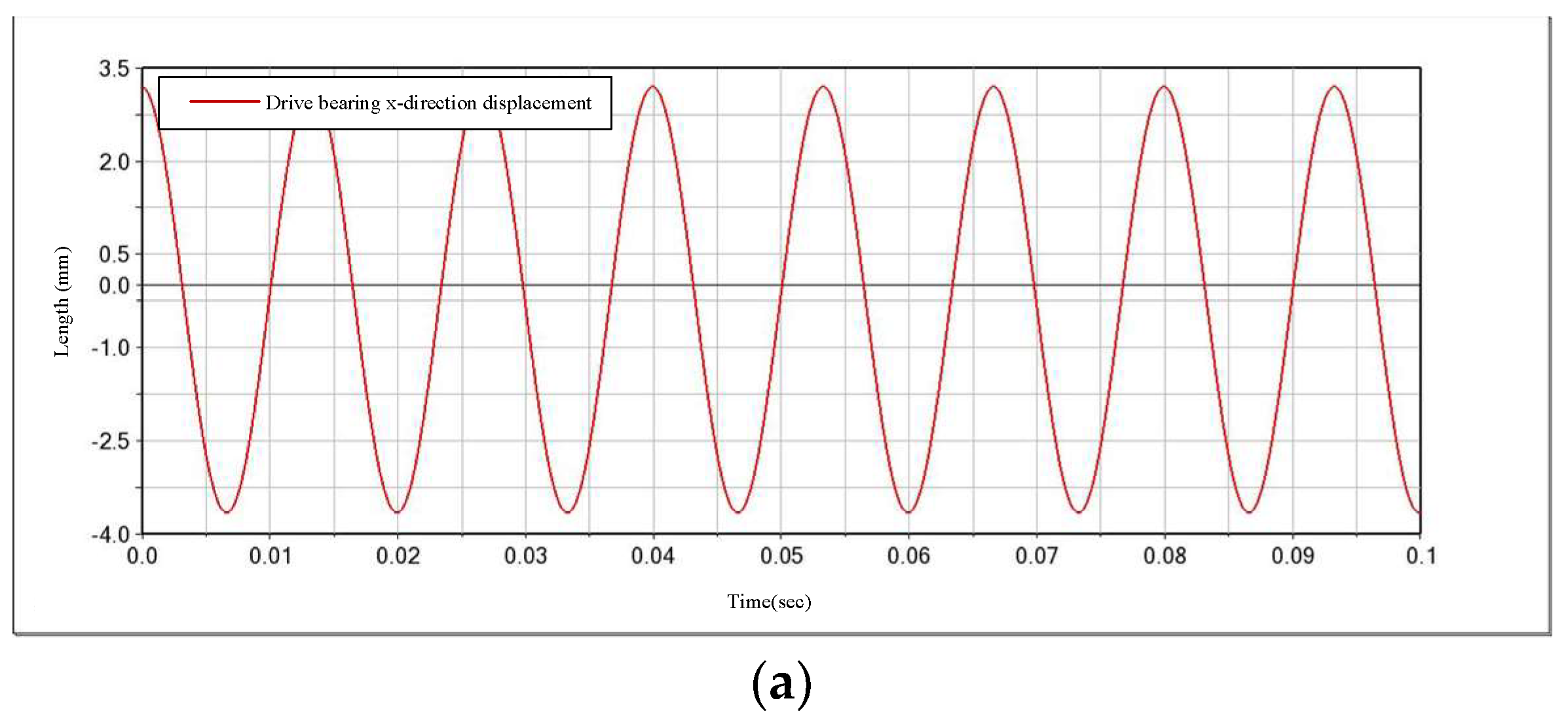
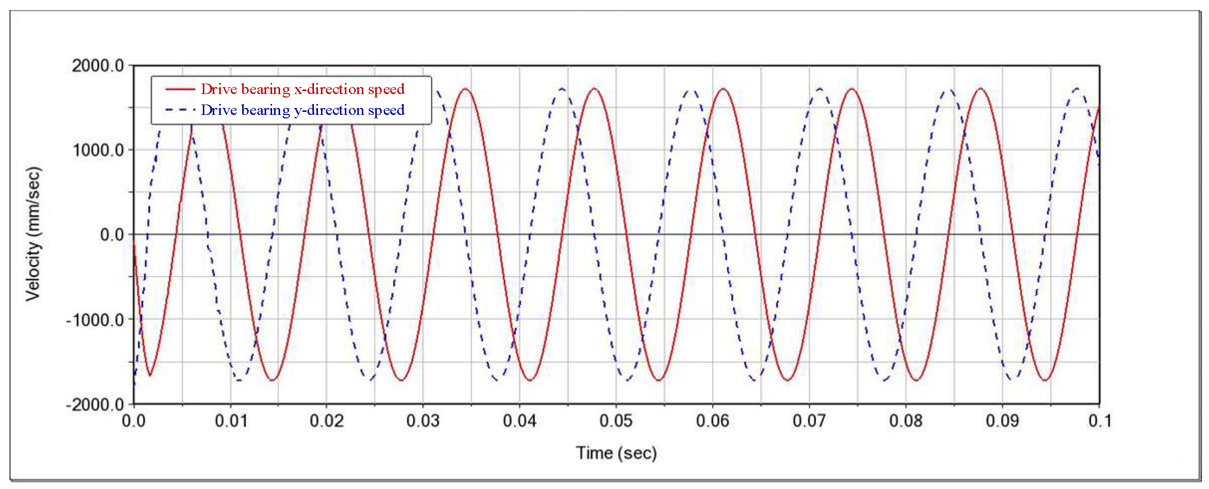
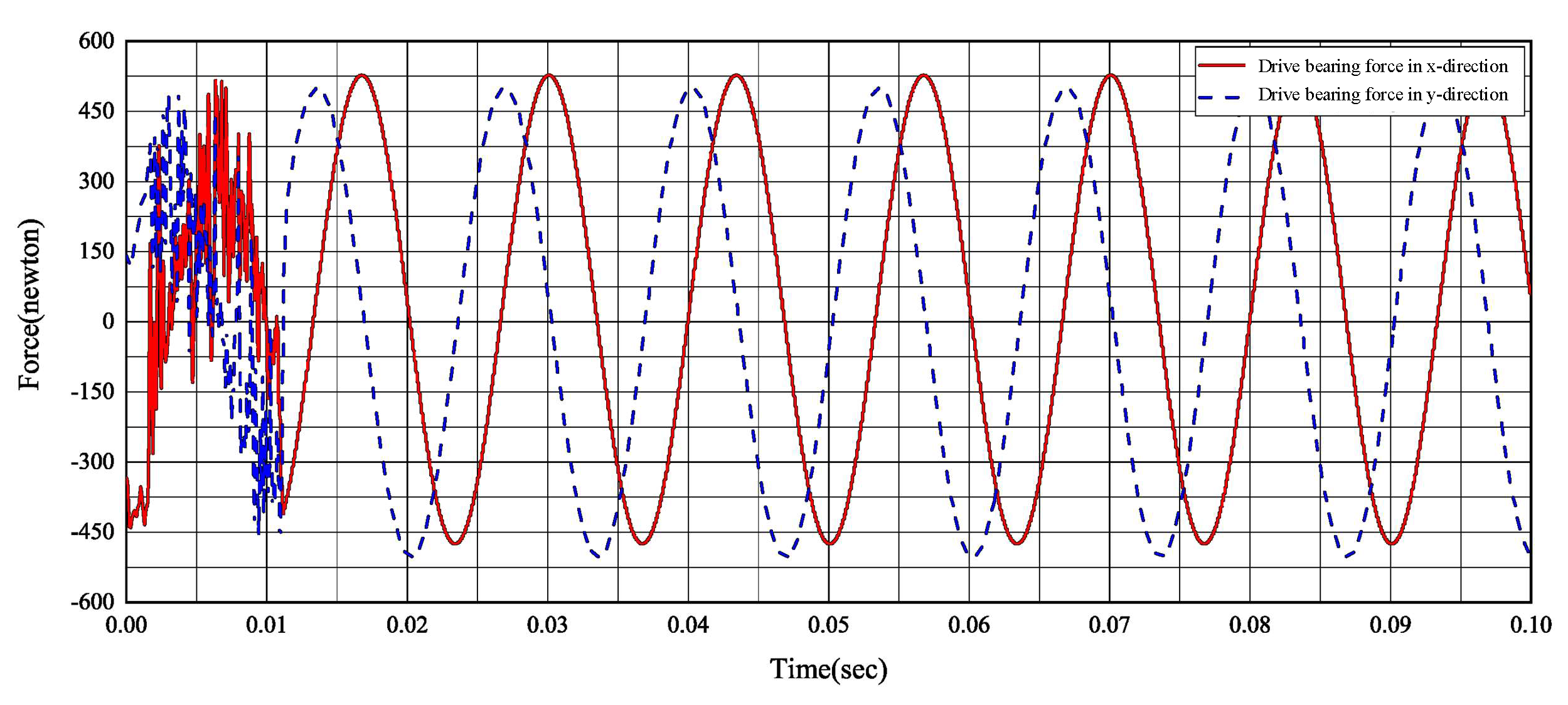
5.2. Dynamic Simulation Analysis

In the operation of scroll compressors at high speeds, the eccentric mass within the rotor system induces the creation of centrifugal inertia forces. These forces can have a substantial impact on overall machine stability and may result in increased vibration, unbalanced operation, and other issues that could affect normal functionality and performance [19,20]. In the virtual prototype, the rotor system model includes measurement variables at the drive-bearing position to measure the magnitude of force applied to the bearing.
When the measured variables are established, Figure 8 presents the results, highlighting the initial substantial force impacts on the drive bearings, along the horizontal and vertical directions. These impact forces are triggered by the gravity of the eccentric wheel and scroll disk, in close proximity to the drive bearings, and the rotational inertia forces accompanying them.
At the same time, the data presented in Figure 8 highlight an increase in the range of force fluctuations on the drive bearing, in both horizontal and vertical directions, showing clear cyclical changes. This cyclical change in force fluctuations leads to wear and tear of the bearing, reducing its life span.
In addition, the force transmitted to the compressor casing from the drive bearing results in severe vibration of the compressor, which negatively affects the overall performance of the machine. This indicates that there are still some unbalanced forces on the main shaft, due to gas forces, necessitating further optimization of the eccentric components of the compressor.

6. Optimization of Drivetrain Dynamic Balance Model

6.1. Model Parameterization

Given the complex structure of the transmission system, it is not feasible to modify the mass and shape dimensions of specific components such as the dynamic vortex disc. Therefore, this study focuses on optimizing the eccentric wheel as the primary target. The eccentric wheel orientation in the rotor system model is the primary determinant of the eccentric wheel mass center coordinate position, which is used as a design variable: DV_1—X-coordinate position of the eccentric wheel mass center; DV_2—Y-coordinate position of the eccentric wheel mass center; DV_3—Z-coordinate position of the eccentric wheel mass center. Based on the eccentric wheel coordinate position, a reasonable variation interval is set for the center-of-mass coordinates of the eccentric wheel, as shown in Table 3. The coordinate parameters of the eccentric wheel are then assigned values within this interval during the optimization process.

6.2. Determination of the Objective Function

The objective function in a measurement system is typically a quantity that is intended to be optimized. In this study, we defined the range of force fluctuations in the horizontal and vertical directions at the drive bearing as the objective function to be optimized. The two measurement variables we defined are the following: Tx (the force in the horizontal direction of the drive bearing) and Ty (the force in the vertical direction of the drive bearing). The objective function we targeted was a minimum value of Tx and Ty to minimize the overall value.

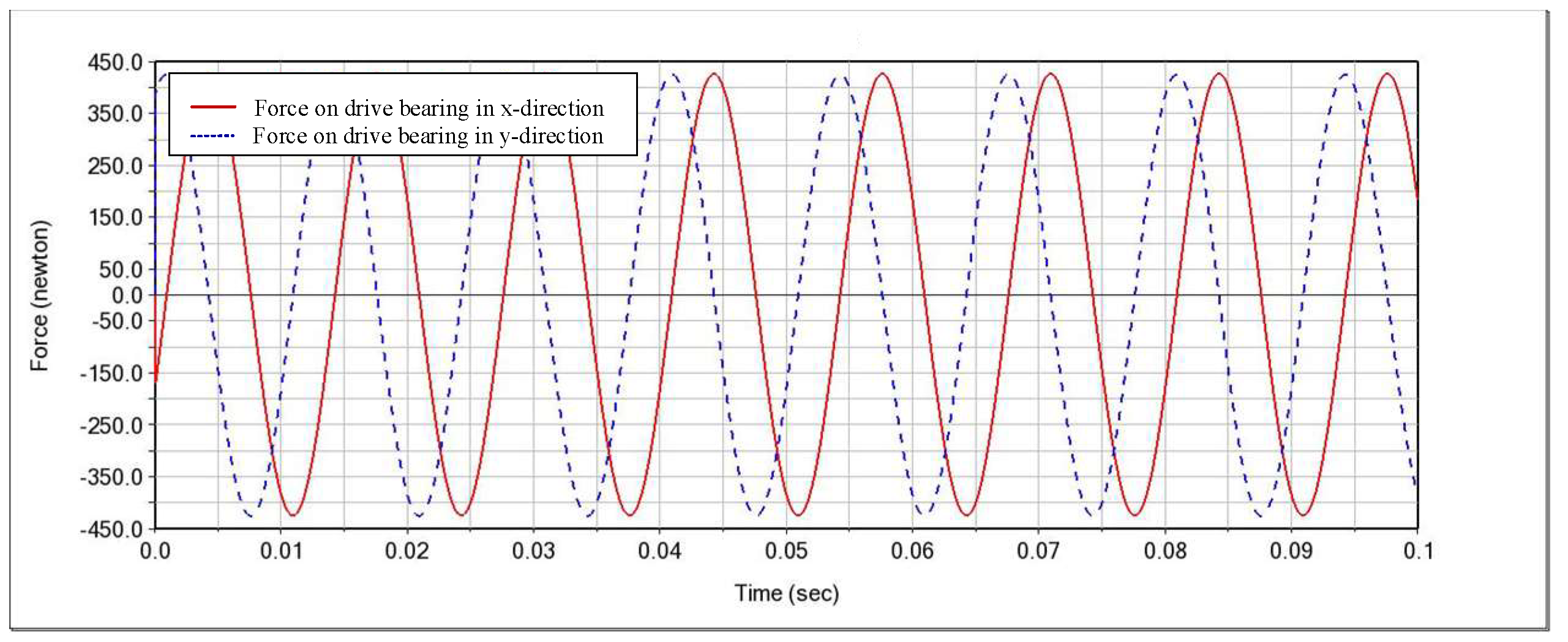
6.3. Optimization Analysis

Parameterizing design variables is a process where a range of values is provided for each variable. Once parameterization is complete, ADAMS/View 2020 automatically determines the actual value of each variable and runs the corresponding simulation. For each set of design variables, a single simulation is performed. The results of each simulation are recorded, including the minimum value of the objective function and an approximation of the sensitivity. This information is presented in Table 4.
The initial value sensitivity represents the slope of the objective function relative to the design variable, and from Table 4, it can be seen that the initial value sensitivity of DV_1 is the largest. That is, it indicates that the value of DV_1 has the greatest influence on the objective function, so DV_1 is chosen as the design variable for dynamic balance optimization. The value of the design variable DV_1 obtained after iterative calculations to minimize the objective function is 4.105.
With the optimal design parameters established, the initial parameters of the relevant components were adjusted in ADAMS and simulated again, and the bearing force of the drive shaft was simulated, as shown in Figure 9.
From the simulation curve results graph in Figure 9, it can be seen that the fluctuation range of the bearing force of the optimized drive shaft is significantly lower than the fluctuation range of the pre-optimization. This is because the peak value has been reduced by 18% compared to pre-optimization, and this moderation has significantly minimized the impact of the bearing at the initial stage. This optimization achieved the desired goals without changing the eccentric wheel mass. This result provides ideas for further optimization of the eccentric wheel shape.

7. Conclusions

During the continuous and uninterrupted operation of an electric scroll compressor, the gas forces acting on the orbiting scroll of the rotor system create a significant and dynamically significant imbalance in the main shaft, which in turn leads to an almost immediate displacement in the center of mass of the drive bearing, coupled with an alarming and uncontrollable increase in the range of fluctuations in force. This excessive and constant increase in force and vibration poses a serious threat to compressor reliability and safety. Therefore, it is of great importance to effectively reduce the force on the drive bearing and improve the dynamic performance of the rotor system of the scroll compressor. To solve this problem, such a parametric optimization method can be used to optimize the positioning of the center-of-mass coordinates of the eccentric wheel of the relevant components of the rotor system of the scroll compressor, helping to alleviate the imbalance in force and vibration generated by the gas forces. By using this method, the critical parameters involved in compressor operation can be optimized, and the relevant parameters after optimization can be derived and simulated again. By comparing the data obtained before and after optimization, it can be seen that optimization effectively reduces the force on the drive bearing, thereby improving the dynamic performance of the rotor system of the scroll compressor, ensuring the smooth and efficient operation of the compressor and ultimately extending the life of the compressor.

Author Contributions

Writing—original draft preparation, B.Y. and M.Y.; writing—review and editing, A.L., X.L., F.G. and M.G. All authors have read and agreed to the published version of the manuscript.

Funding

This study was supported by the National Natural Science Foundation of China (grant no. 12372079) and the Natural Science Foundation of Jiangsu Province, China (grant no. BK20201470, BK20220687).

Institutional Review Board Statement

Not applicable.

Informed Consent Statement

Not applicable.

Data Availability Statement

The data presented in this study are available on request from the corresponding author. The data are not publicly available due to privacy.

Acknowledgments

We appreciate the editors and referees for their beneficial remarks and advice, which have greatly contributed to the clarity of the paper. The authors are grateful to Xuan Ma, Jiajia Zou and Xingyu Zhang from the Nanjing Institute of Technology, for their valuable discussions.

Conflicts of Interest

The authors declare no conflicts of interest.

Nomenclature

F total radial force (N) p s the suction pressure (Mpa)
F a axial gas force (N) p t the pitch of the scroll teeth (mm)
F r radial gas force (N)
F t tangential gas force (N) η the included angles of the line of action of the total radial force with respect to the direction of the principal coordinates (rad)
p the compression chamber pressure (Mpa)
V the compression chamber volume ( m m 3 )
a the radius of the base circle (mm)
F c c the equivalent effect of the centrifugal inertial force of the moving vortex disk transformed to the 1-1 action surface (N) γ the included angles of the line of action of the total radial force with respect to the direction of the radial gas force (rad)
S x the displacement of the centre of mass turned in the x-direction (mm) h the tooth height (mm)
θ the crankshaft angle (rad)
S y the displacement of the centre of mass turned in the y-direction (mm) ω the angular velocity of rotation of the drive system (rad/s)
V x the drive-bearing center-of-mass velocity in the x-direction (mm/s) i the compression chamber number
V y the drive-bearing center-of-mass velocity in the y-direction (mm/s)

References

  1. Yang, W.Z.; Feng, Z.G.; Su, Y.F. Simulation and analysis of dynamic balance of scroll compressor’s transmission system. Mach. Des. Manuf. 2023, 80–83. [Google Scholar] [CrossRef]
  2. Pu, J.; Zhang, X.H.; Su, Y.F.; Yao, H. Dynamic characteristics analysis of rotor system of a new high speed scroll compressor. J. Guizhou Univ. (Nat. Sci.) 2020, 37, 23–27. [Google Scholar]
  3. Zhang, Y.B.; Peng, B.; Zhang, P.C.; Sun, J.; Liao, Z.X. Key technologies and application of electric scroll compressors: A Review. Energies 2024, 17, 179. [Google Scholar] [CrossRef]
  4. Li, C.; Wang, H.H.; Zhang, X.D.; Liu, J.Z. Study on the dynamic characteristics of scroll compressor rotor system considering the influence of clearance. Fluid Mach. 2021, 49, 43–50. [Google Scholar] [CrossRef]
  5. Dang, J.W. Study on Dynamic characteristics of rotor system of radial flexible mechanism of scroll compressor. J. Lanzhou Univ. Technol. 2023. [CrossRef]
  6. Zhao, M.; Zhang, Q.; Yan, P.J. Dynamics simulation analysis of drive bearing in scroll compressor with joint clearance. Compress. Technol. 2019, 4, 7–12. [Google Scholar]
  7. Zhao, M.; Li, X.Q. Simulation and rigid-flexible coupling analysis of orbiting scroll overturning of scroll compressor based on ADAMS. J. Lanzhou Univ. Technol. 2021, 47, 61–65. [Google Scholar]
  8. Li, C.; Cui, D.C.; Wang, X.L.; Liu, H.Y. Study on the stability of scroll compressor rotor system considering the influence of gas force. Fluid Mach. 2019, 47, 15–20. [Google Scholar]
  9. Cheng, J.G.; Li, C.; Zhang, Y. Research on Lubrication Characteristics of Scroll Compressor Thrust Bearing. Fluid Mach. 2023, 51, 66–75. [Google Scholar]
  10. Li, Y. Research on Multi-Body Dynamics Characteristics of Scroll Compressor Rotor System. Master’s thesis, Lanzhou University of Technology, Lanzhou, China, 2022. [Google Scholar]
  11. Tiwari, M.; Gupta, K. Dynamic response of an unbalanced rotor supported on ball bearings. J. Sound Vib. 2000, 238, 757–779. [Google Scholar] [CrossRef]
  12. Wang, A.M.; Cheng, X.H.; Meng, G.Y.; Xia, Y.; Wo, L.; Wang, Z.Y. Dynamic analysis and numerical experiments for balancing of the continuous single-disc and single-span rotor-bearing system. Mech. Syst. Signal Process. 2017, 86, 151–176. [Google Scholar] [CrossRef]
  13. Yu, Y.; Li, C.; Zhao, M.; Zheng, S.S. Analysis of bearing loads for scroll compressor considering phase-angled counterweights. Appl. Mech. Mater. 2012, 226–228, 483–486. [Google Scholar] [CrossRef]
  14. Ahn, S.; Choi, S.; Lee, B.; Rhim, Y.C. Analysis of thrust bearing in high-side shell type scroll compressor. Int. J. Refrig. 2016, 69, 251–260. [Google Scholar] [CrossRef]
  15. Kim, M.S.; Shim, J.; Kim, J.; Jang, D.G.; Park, S.S. Multiphysics simulation and experiment of a thrust bearing in scroll compressors. Tribol. Int. 2020, 142, 105969. [Google Scholar] [CrossRef]
  16. Makino, M.; Ogawa, N.; Abe, Y.; Fujiwara, Y. Automotive Air-Conditioning Electrically Driven Compressor; SAE Technical Paper; SAE International: Warrendale, PA, USA, 2003. [Google Scholar]
  17. Yu, Y.; Wang, X.M. Transient flow analysis for multi-state automotive scroll compressors. J. Phys. Conf. Ser. 2020, 1601, 042006. [Google Scholar] [CrossRef]
  18. Ma, L.Y. Compressor bearing dynamics analysis and life prediction. China Sci. Technol. Inf. 2023, 113–116. [Google Scholar] [CrossRef]
  19. Qian, W.X.; Gao, Q.H.; Li, X.Y.; Li, Y.N. Simulation study of dynamic characteristics of axial piston pump based on virtual prototype. Chin. Hydraul. Pneum. 2017, 61–67. [Google Scholar] [CrossRef]
  20. Sun, Y.; Jiang, J.H.; Cheng, M.Z.; Wang, Y.C. Research and application of virtual prototype technology base on dynamic simulation and analysis of axial piston pump. Chin. Hydraul. Pneum. 2010, 25–27. [Google Scholar] [CrossRef]
Figure 1. Schematic diagram of eccentric spindle structure.
Applsci 14 05024 g001
Figure 2. Structural force diagram of moving vortex disc.
Applsci 14 05024 g002
Figure 3. Force diagram of drive bearing.
Applsci 14 05024 g003
Figure 4. Assembly diagram of rotor system.
Applsci 14 05024 g004
Figure 5. ADAMS dynamics model.
Applsci 14 05024 g005
Figure 6. Displacement curves in horizontal and vertical directions of the center of mass of the dynamic bearing. (a) Displacement curve in the horizontal direction of the center of mass of the dynamic bearing. (b) Displacement curve in the vertical direction of the center of mass of the dynamic bearing.
Applsci 14 05024 g006aApplsci 14 05024 g006b
Figure 7. Velocity profiles of dynamic−bearing center of mass in horizontal and vertical directions.
Applsci 14 05024 g007
Figure 8. Dynamic−bearing vertical direction force diagram.
Applsci 14 05024 g008
Figure 9. Force diagram of drive bearing after optimization of objective function.
Applsci 14 05024 g009
Table 1. Constraint relationships between moving parts.
Serial NumberPartsMovement Subtypes
1Spindle, Permanent Magnet RotorsFixing
2Main Bearing, SpindleHinge connection
3Secondary Bearing, SpindleHinge connection
4Balancing Iron, Permanent Magnet RotorsFixing
5Biasing Wheel, SpindleFixing
6Biasing Wheel, Drive BearingsFixing
7Drive Bearings, Orbiting ScrollHinge connection
8Secondary BearingRelative geodesic fixation
Table 2. Scroll compressor parameters.
TitleNotationNumerical Value
Base circle radius r a 1.65 mm
Involute start angle α 51.6°
Turning radius R o r 3.77 mm
Pitch of vortex ring p t 10.3 mm
Vortex ring wall thickness t 2.8 mm
Vortex ring height h 19 mm
Number of swirl rings n 2.5
Maximum spread angle ϕ E 5.5 π
Table 3. Initial values and variation intervals of optimization variables.
Design VariableStarting ValueMinimum ValueMaximum Value
DV_1−10.9−2015
DV_22.3−1520
DV_3−94.0−15050
Table 4. Data on the results of the design study for the variation in the parameters.
Design VariableVariable Initial ValueInitial Value Sensitivity
DV_1−10.920.5
DV_22.3−1.96
DV_3−94.00.14
Disclaimer/Publisher’s Note: The statements, opinions and data contained in all publications are solely those of the individual author(s) and contributor(s) and not of MDPI and/or the editor(s). MDPI and/or the editor(s) disclaim responsibility for any injury to people or property resulting from any ideas, methods, instructions or products referred to in the content.

