Article

Design and Multi-Objective Optimization for Improving Torque Performance of a Permanent Magnet-Assisted Synchronous Reluctance Motor

1
School of Electrical Engineering, Liaoning University of Technology, Jinzhou 121001, China
2
School of Mechanical Engineering and Automation, Harbin Institute of Technology, Shenzhen 518055, China
*
Author to whom correspondence should be addressed.
Appl. Sci. 2024, 14(12), 5253; https://doi.org/10.3390/app14125253
Submission received: 29 April 2024 / Revised: 14 June 2024 / Accepted: 14 June 2024 / Published: 17 June 2024

Abstract

:
Permanent magnet-assisted synchronous reluctance motors (PMA-SynRMs) are widely used in various industries as a relatively inexpensive and high-performance energy conversion device. The model proposed in this article relies on a magnetic pole-biased permanent magnet synchronous reluctance motor with a magnetic focusing effect. Two types of models with Halbach array and magnetic focusing effect have been proposed, which increase excitation and make the internal magnetic circuit of the rotor more saturated, thereby achieving higher electromagnetic torque. Through finite element simulation analysis and verification, the motor characteristics of the basic and proposed permanent magnet-assisted synchronous reluctance motor were calculated, including the air gap flux density and back electromotive force (EMF) in no-load analysis, as well as the average torque, torque ripple, and efficiency in load analysis. In addition, multi-objective optimization was also conducted on the rotor topology structure of proposed model two, using the uniform Latin hypercube sampling method to uniformly sample the data samples and the Pearson correlation coefficients to perform a sensitivity analysis on the data. The pilOPT multi-objective autonomous optimization algorithm was used to perform multi-objective autonomous optimization on parameters with high correlation, and the best-found solution based on the Pareto front was selected. Compared with proposed model two, the average torque of the optimized model increased by 18.14%, the efficiency increased by 1.05% and the torque ripple decreased by 5.22%. Finally, the anti-demagnetization performance of the optimized model’s permanent magnet was analyzed.

1. Introduction

Permanent magnet motors have the advantages of small size, high output torque, high efficiency, good speed regulation performance, and strong reliability, and are extensively used in different fields such as automobiles, aerospace, and ships [1,2]. The performance of permanent magnets closely affects the performance of motors. At the moment, by applying high-performance permanent magnet material, NdFeB, the torque and efficiency of permanent magnet motors have been significantly improved [3,4]. But due to the significant fluctuations and high prices of NdFeB, and NdFeB materials being non-renewable resources, their reserves are decreasing year by year with continuous mining [5,6]. Permanent magnet-assisted synchronous reluctance motors (PMA-SynRMs) typically have fewer permanent magnets for the same volume than conventional permanent magnet synchronous motors. As a result, PMA-SynRMs have better economics. PMA-SynRMs have gradually entered the public sphere and become a research direction for many scholars. PMA-SynRMs, by integrating the advantages of permanent magnet motors and reluctance motors [7], have gradually gained widespread attention due to their advantages such as low permanent magnet usage, high torque and power density, and a wide weak magnetic speed regulation range [8,9].
Nowadays, the design of permanent magnets, magnetic circuit analysis, and magnetic resistance design are the research hotspots of PMA-SynRM [10,11,12]. By analyzing the quantity, volume, geometric shape, and mixing of multiple materials of permanent magnets [13,14,15,16], PMA-SynRM achieved better torque performance. Because of the need for large-scale production of permanent magnets and the more complex and difficult installation of long arc-shaped permanent magnets, this article uses segmented rectangular permanent magnets for the convenience of manufacturing and assembly [17]. In addition, the arrangement of permanent magnets also directly affects the performance of PMA-SynRM. The magnetic pole-biased PMA-SynRM [18] biases the permanent magnet to one side of the magnetic circuit and changes the q-axis phase by changing the magnetic flux direction, maximizing both permanent-magnet torque and reluctance torque at the same current phase angle to increase the total superimposed torque. But the magnetic pole-biased PMA-SynRM will cause the loss of other magnetic circuits, causing the rotor magnetic circuit not to reach saturation. Moreover, because the arrangement of permanent magnets is irrational, the magnetic force of permanent magnets is not well utilized. However, the Halbach array has been widely used as a permanent magnet arrangement that achieves high magnetic field strength in specific directions [19,20]. In recent years, the application of Halbach arrays in permanent magnet motors has become a research hotspot, such as in permanent disk motors [21], permanent magnet linear motors [22], permanent magnet vernier motors [23], and so on. However, there is little research on the application of Halbach arrays in PMA-SynRM. Therefore, this paper proposes two models based on the basic model of a permanent magnet arrangement with a magnetic flux focusing effect, combined with the permanent magnet arrangement of Halbach array. The magnetic flux focusing effect is obvious in the magnetic circuit on both sides of the rotor monopole of the proposed model, and the air gap magnetic density is significantly improved. By increasing the excitation, the average torque and efficiency of the proposed model are effectively improved.
In this paper, the model of reference [18] is optimized with the aim of improving the average torque. This article proposes two PMA-SynRM models that combine Halbach arrays and exhibit magnetic focusing effects. Firstly, using the finite element analysis (FEA) method to conduct simulations on the model, the magnetic field distribution of three models under no-load conditions was analyzed, and the characteristics of the proposed model combined with Halbach array magnetization method and magnetic focusing effect were verified. Subsequently, performance analysis and comparison were conducted on the basic model and the proposed model under load conditions. Afterwards, the rotor topology parameters of proposed model two were analyzed using uniform Latin hypercube sampling and sensitivity analysis [24,25]. The pilOPT multi-objective global autonomous optimization algorithm was used to perform multi-objective optimization on the topology parameters with high correlation in proposed model two [26,27,28] and to compare their torque characteristics before and after optimization. Eventually, the demagnetization performance of the optimized model’s permanent magnet under overcurrent conditions was verified [29].
Targeting the characteristic of low average torque in magnetic pole-biased PMA-SynRM and based on the above research, this article proposes two PMA-SynRM models that combine Halbach array permanent magnet placement methods. The article has the following chapter arrangement: In Section 2, the motor topology structure of the basic model and the proposed models are introduced, and the performance of the three models in both no-load and load operating modes are compared, attesting to the torque improvement of proposed model two. In Section 3, maximization of the average torque as the objective of moment optimization under the condition of torque ripple being less than 30% and sensitivity analysis and multi-objective optimization are carried out on the rotor topology size parameters of proposed model two. In Section 4, by comparing and analyzing the performance of the optimized model with proposed model two, it was found that the average torque of the optimized model significantly increased, and the torque ripple slightly decreased. Anti-demagnetization analysis was conducted on the optimized model, proving that the optimized model has positive anti-demagnetization performance. In Section 5, a brief summary is provided for this article.

2. Machine Topology and Simulation Results

The topology and specifications of the machine, and the no-load and load conditions of the machine are simulated and analyzed in this section.

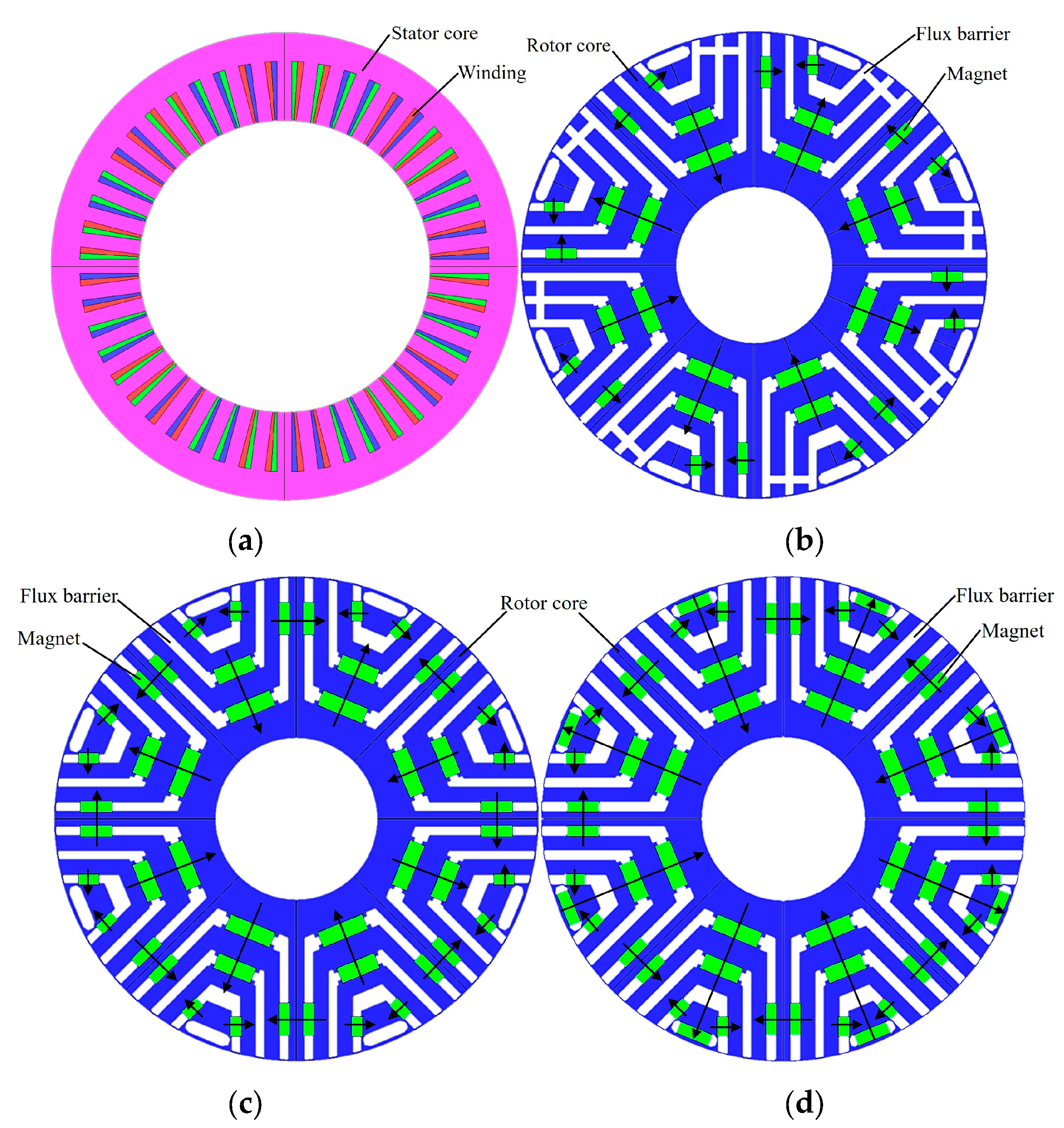
2.1. Machine Topology

The three models in this article are all 8-pole and 48-slot PMA-SynRM with three layers of U-shaped flux barriers. The stator core and rotor core were stacked with 50JN1300 (Sourced from JFE Steel, Tokyo, Japan) silicon steel sheets, and the quantity of silicon steel sheets in the three models was very similar. The permanent magnet used was an NMX-42F (Sourced from Hitachi, Tokyo, Japan) NdFeB permanent magnet, with a residual magnetism of 1.28 T. For the accuracy of the simulation, the three models were configured with the same stator structure and winding. The stator and rotor topology of the basic model and proposed models one and two are shown in Figure 1. The arrow direction in Figure 1 represents the magnetization direction of the permanent magnet. It should be noted that proposed model one is very similar to proposed model two in terms of rotor structure. However, proposed model two has an additional permanent magnet in the flux barrier at the top of the rotor compared to proposed model one.
Table 1 shows the same dimensional parameters for the three models. The volumes of the permanent magnets for the basic model and proposed models one and two are 24,800 mm3, 32,000 mm3 and 37,200 mm3, respectively. The arrangement of permanent magnets in the basic model has a certain magnetic focusing effect, but the asymmetric structure causes a blockage on the other side, resulting in a decrease in the utilization rate of permanent magnets. By utilizing the advantages of its magnetic focusing effect, proposed model one is proposed, which enables the magnetic circuits on both sides of the rotor to have magnetic focusing effect in a single stage. Proposed model one and proposed model two form a permanent magnet arrangement of Halbach arrays as shown in Figure 2, further increasing the q-axis magnetic flux. According to Figure 3, a planar expansion diagram of proposed model two can provide a clearer view of the permanent magnet arrangement and Halbach array magnetic focusing effect. The pink arrow in Figure 2 and Figure 3 is the magnetization direction of the permanent magnet, and the permanent magnets in the adjacent rotor barrier ribs can form a series. The permanent magnet in the middle of the rotor barrier and the permanent magnet in the rib of the barrier form the arrangement of the Halbach array. Such a permanent magnet arrangement can effectively use the magnetic circuit inside the rotor, the magnetic flux aggregation effect is obvious, and the excitation effect is better. This paper will use finite element simulation results to prove the theory.
The vector diagram of proposed model two was established according to Figure 3, as shown in Figure 4. According to Figure 4, the voltage equation, the magnetic chain equation and the electromagnetic torque equation can be listed as shown in Equations (1)–(3), respectively.
u d = d ψ d dt ω ψ q + R i d u q = d ψ q dt + ω ψ d + R i q
ψ d = L d i d + ψ PM ψ q = L q i q
T e = 3 2 p ( ψ d i q ψ q i d ) = 3 2 p ( ψ PM i q + ( L d L q ) i d i q ) = 3 2 p ψ PM i s cos θ + 3 4 p ( L d L q ) i s 2 sin ( 2 θ )
where, u d and u q are voltages of d-axis and q-axis, respectively; i d and i q are currents of d-axis and q-axis, respectively; ψ d and ψ q are magnetic chains of d-axis and q-axis, respectively; L d and L q are the inductance of d-axis and q-axis, respectively; R is phase resistance; ω is electrical angular velocity; θ is current angle; ψ PM is permanent magnet flux linkage; p is pole-pairs number; i s is armature current amplitude.

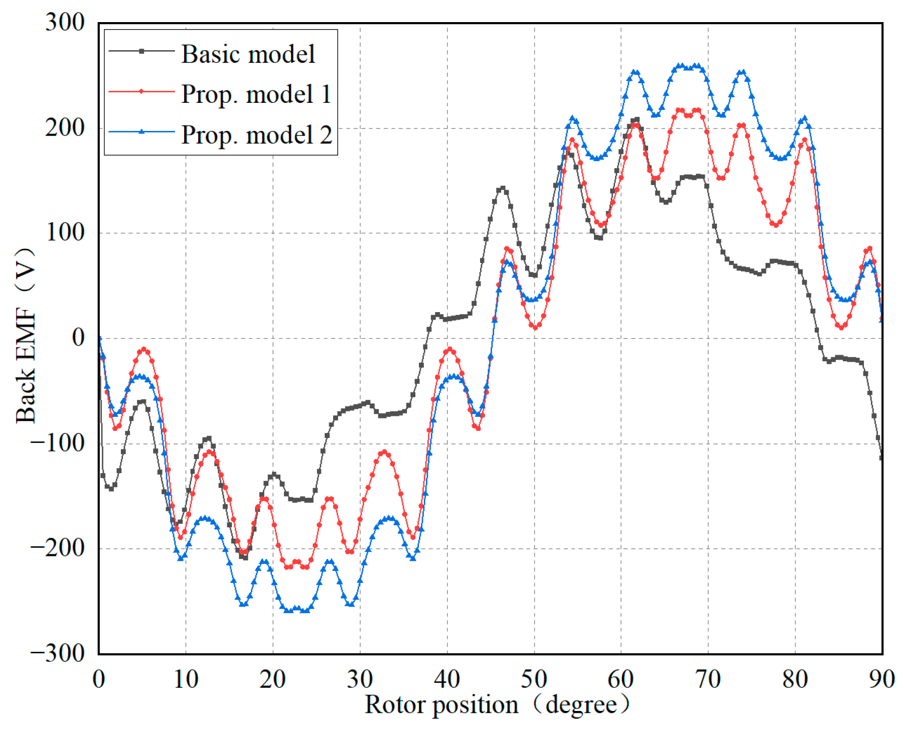
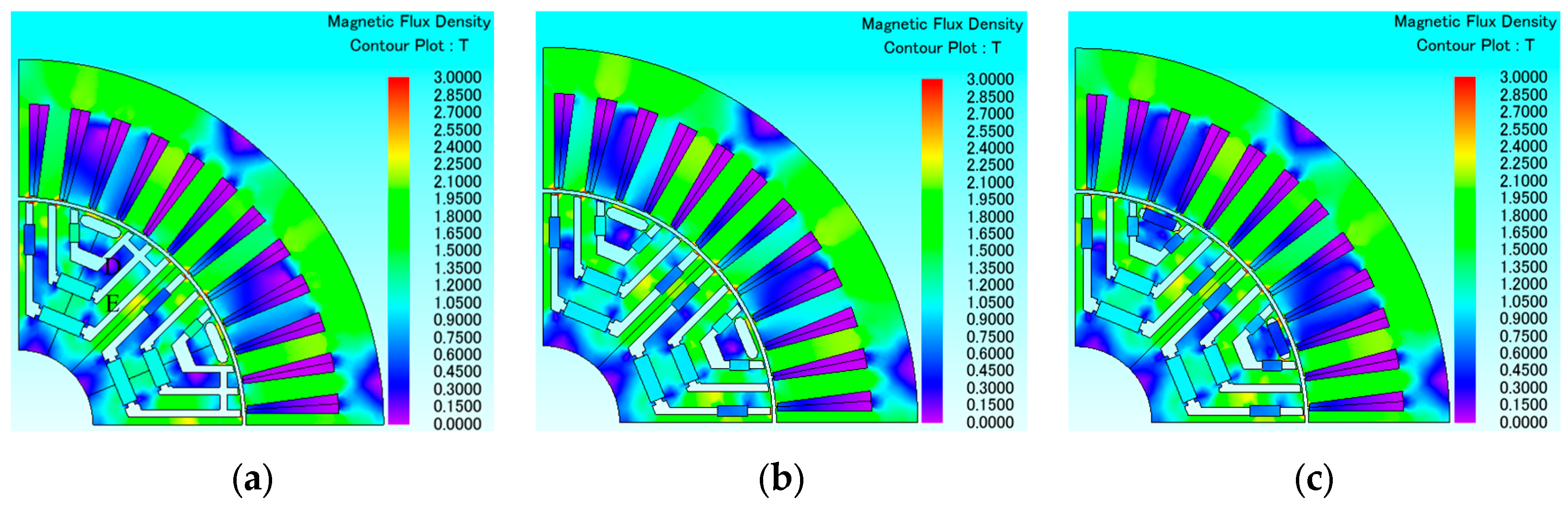
2.2. No-Load Characteristics Analysis

In order to further reveal the advantages of the permanent magnet arrangement combined with the Halbach array and the magnetic flux focusing effect, a comparative analysis was conducted on the no-load operation of the basic model and proposed models one and two in this paper. Figure 5 shows the magnetic field distribution maps of three models under no-load conditions. Figure 5a is the magnetic field distribution map of the basic model, and Figure 5b,c are the magnetic field distribution maps of proposed models one and two, respectively. Compared with the basic model, proposed models one and two significantly increase the number of magnetic field lines in the C region of the stator. However, proposed model one has almost no magnetic flux flowing through zone A. The air gap magnetic density of proposed model one decreases almost to zero at a phase angle between 60 and 75 degrees in Figure 6. At the same time, the back electromotive force (EMF) is also affected accordingly. The back EMF of proposed model one exhibits greater fluctuations than that of proposed model two in Figure 7. Therefore, in proposed model two, a permanent magnet was added at B to fill the gap in magnetic flux in zone A. After adding the permanent magnet, it was found that not only did it increase the magnetic flux in zone A, but it also further increased excitation and increased the magnetic density in the stator. Although the maximum air gap magnetic flux density of proposed model two slightly decreased compared to the base model and proposed model one, the air gap magnetic flux density rebounded at a phase angle between 60 and 75 degrees in Figure 6. According to Table 2, regarding the air gap magnetic flux density, the root mean square (RMS) value of proposed model two is higher than that of the basic model, but slightly lower than that of proposed model one, and the RMS value of the back EMF is the highest among the three models.

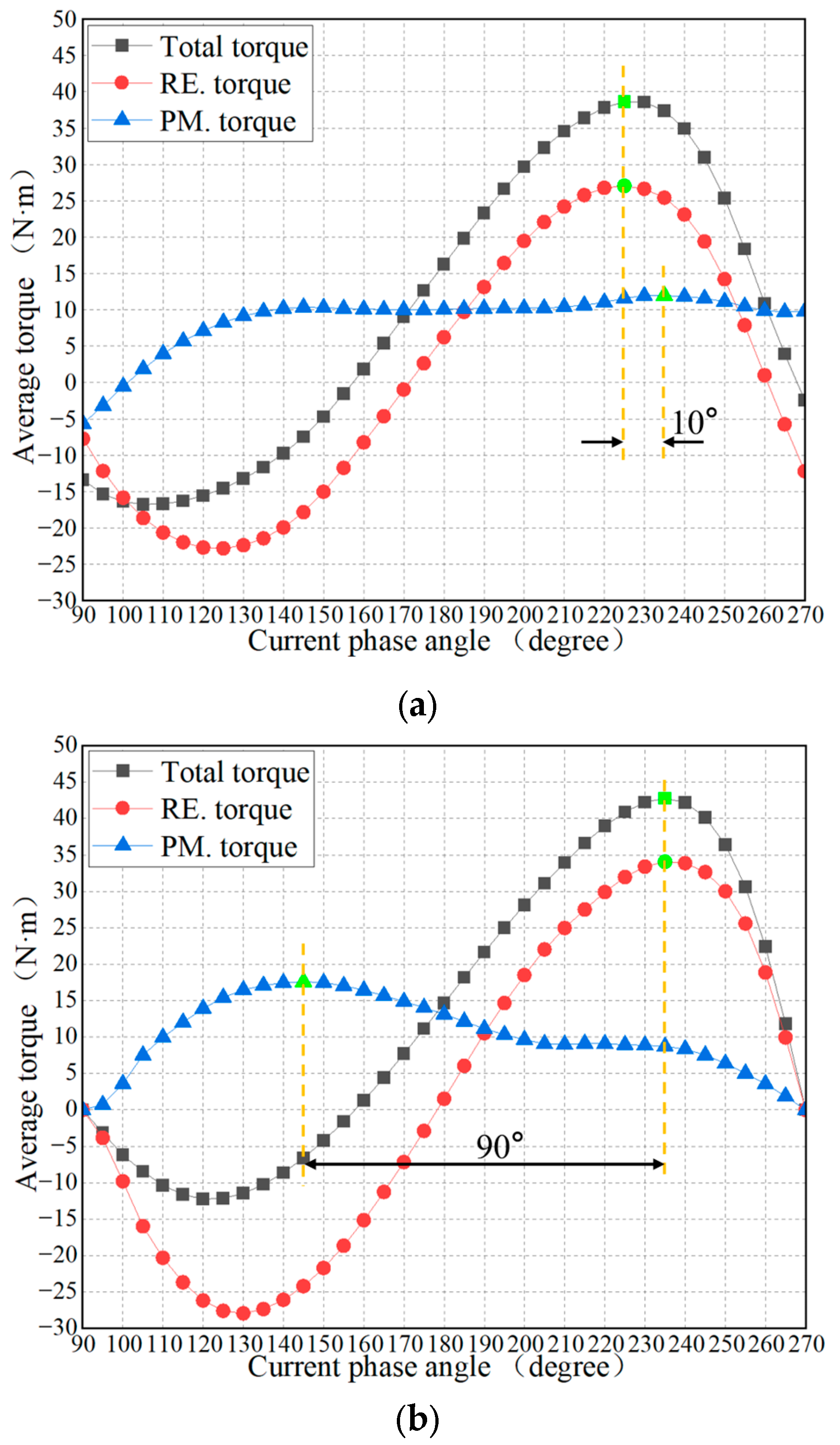
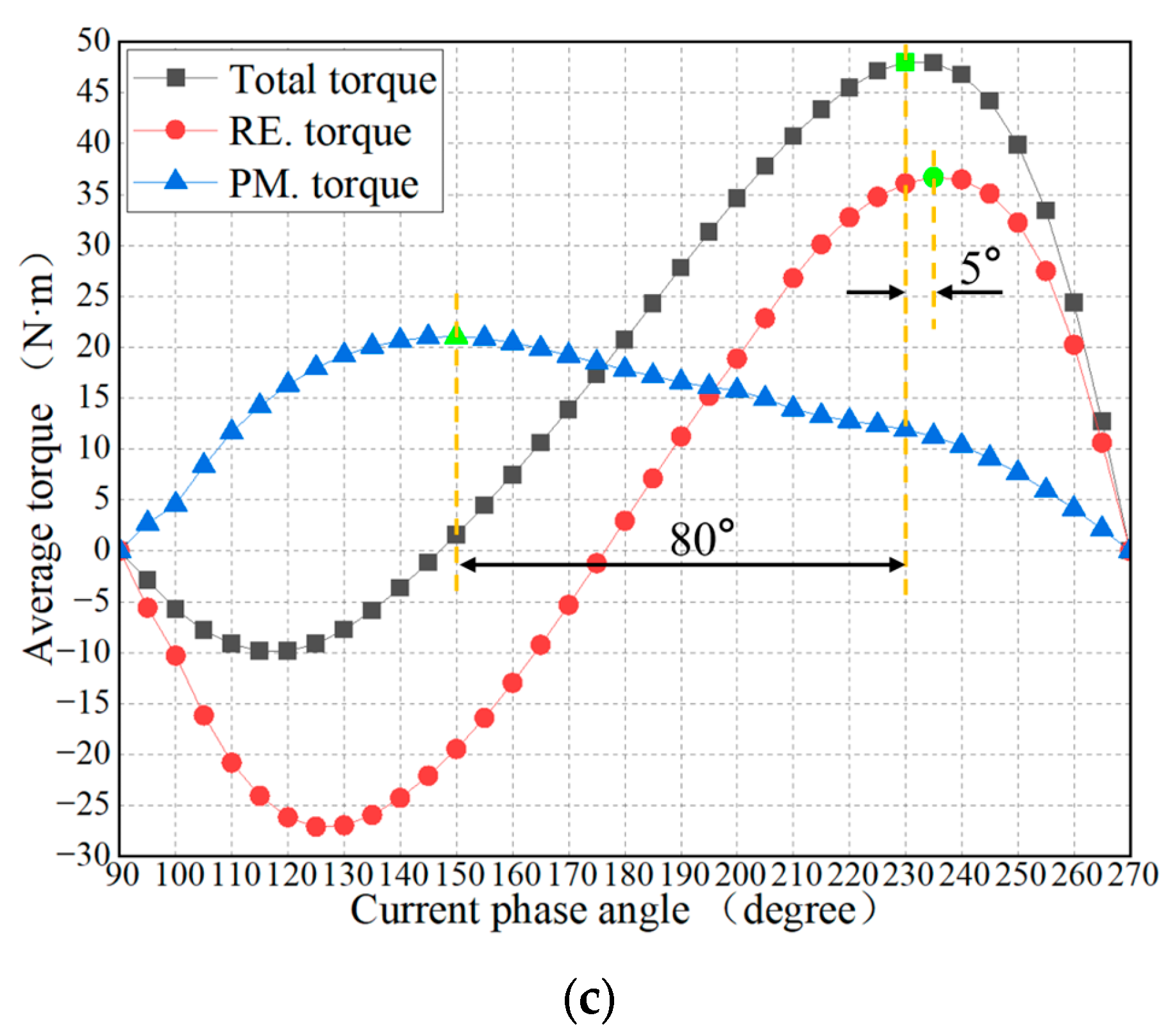
2.3. On-Load Characteristics Analysis

To further verify the torque performance of the three models, on-load simulations were conducted on the three structural models to verify their performance. Figure 8 shows cloud maps of magnetic flux density for each model at maximum average torque at a current RMS value of 10 A. From Figure 8a, it can be seen that due to the basic model blocking one side of the magnetic circuit, the magnetic flux density in the D and E regions is significantly lower than that of proposed model two. Proposed model two has a more sufficient and uniform magnetic flux density distribution in the D and E magnetic circuits, indicating that proposed model two has better utilization of the magnetic circuit.
In Figure 9, the torque of the three models can be seen. The torque of proposed model two is greater than that of the base model and proposed mode one. The formulas for average torque and torque ripple are shown in Equations (4) and (5).
Tave = i = 1 n T i n
Trip = Tmax Tmin Tave × 100 %
where, Tave and Trip are the average torque and torque ripple, respectively; n is the number of steps of the motor in one operating period; T i is the torque of the motor at step i; Tmax and Tmin are the maximum and minimum torque of the motor in one operating period, respectively.
According to Table 3, compared with the basic model, the average torque of proposed model two increased by 24.08%, and its efficiency also increased by 1.45% at a speed of 1500 rpm, but the torque ripple increased by 18.34%. The total loss in Table 3 contains iron loss and copper loss. Among them, the iron loss contains hysteresis loss and eddy current loss. In order to raise the torque performance of proposed model two, multi-objective optimization on the rotor topology structure of proposed model two was conducted.
The output torque of a PMA-SynRM is mainly composed of permanent magnet torque and reluctance torque. The frozen permeability method was applied to decompose the total torque of the three models at different phase angles. The permanent magnet torque, reluctance torque, and total torque for the three models are shown in Figure 10. It should be noted that the green markers in Figure 10 are the points of maximum torque. It can be seen from Figure 10 that the phase difference between the maximum value of the total torque and the maximum value of the reluctance torque for the basic model and proposed model one is zero. The phase difference between the maximum value of the total torque and the maximum value of the reluctance torque for proposed model two is also only 5°. Because the basic model is a pole-biased PMA-SynRM, the total torque, permanent magnet torque and reluctance torque are made to peak at the same or similar phase angle by the magnetic chain offset. In Figure 10a, it is shown that the phase difference between the total torque maximum and the permanent magnet torque maximum for the base model is also only 10°. And the phase difference between the maximum value of the total torque and the maximum value of the permanent magnet torque for proposed models one and two are 90° and 80°, respectively. The reluctance torque in all three models is maximized at the same or a similar phase angle to the total torque maximum.

3. Multi-Objective Optimization

Firstly, the size parameters of the flux barrier and permanent magnet in the rotor of proposed model two were introduced. Then, sensitivity analysis was conducted on the size parameters. Finally, multi-objective optimization was performed on parameters with high correlation.

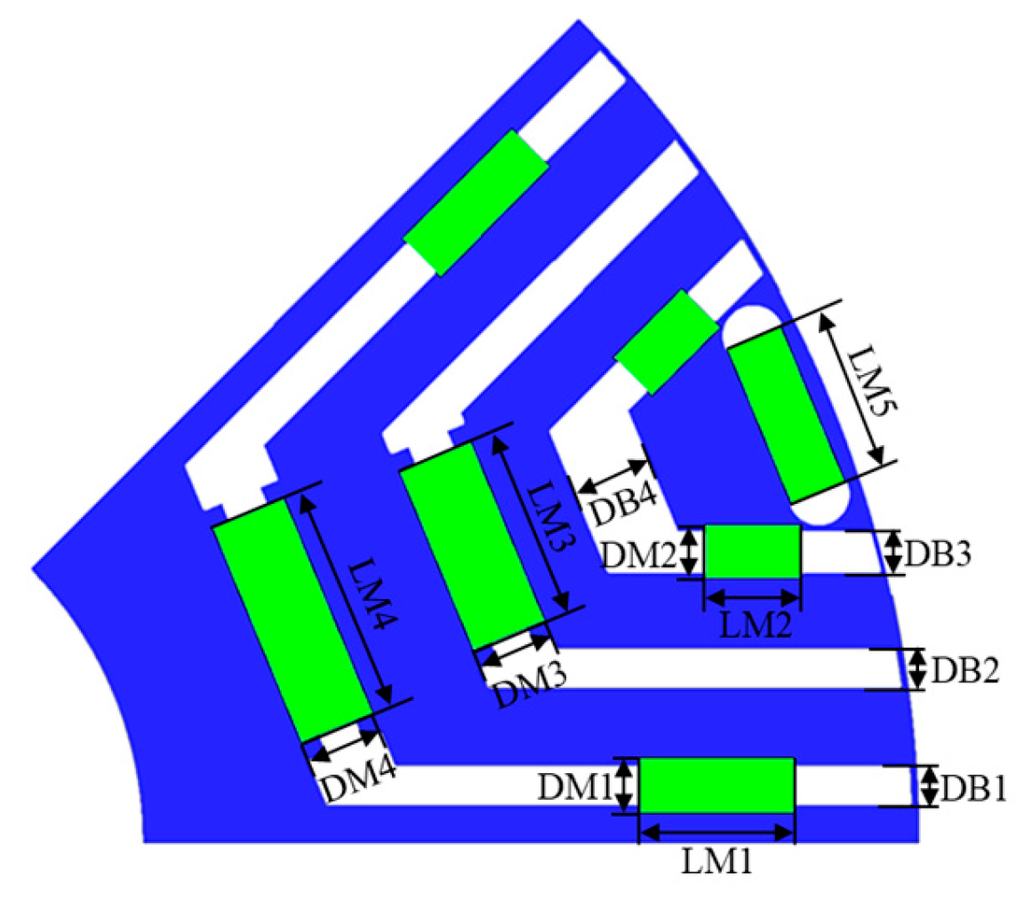
3.1. Multi-Objective Optimization Size

So as to obtain higher torque performance for proposed model two, this research will further optimize the rotor structure size parameters of proposed model two through multi-objective optimization. Figure 11 is a schematic diagram of the rotor topology parameters of proposed model two, and Table 4 shows the value range regarding relevant size parameters. The multi-objective optimization flowchart is shown in Figure 12. The main goal of this multi-objective optimization is to maximize the average torque, followed by minimizing torque ripple as a secondary objective. Therefore, in order to obtain higher average torque and lower torque ripple, the optimized objective functions can be defined using Equations (4) and (5), as shown in Equation (6).
O 1 = max ( Tave ) O 2 = min ( Trip )
where, O 1 and O 2 are the average torque optimization objective and torque ripple optimization objective, respectively.
We set the step size of all relevant parameters to 0.1 mm, conducted sensitivity analysis on their key parameters, removed parameters with a relatively small impact, and then performed multi-objective optimization on the remaining parameters to ensure motor performance while saving as much optimization time as possible.

3.2. Uniform Latin Hypercube Sampling and Sensitivity Analysis

In order to make the data sampling coverage more comprehensive, the uniform Latin hypercube sampling method was selected for data collection, and ultimately 134 sets of data were extracted for sensitivity analysis. The sensitivity concept is the Pearson correlation coefficient, which ranges from −1 to +1. Negative values indicate a negative correlation with the response value, whereas positive values indicate a positive correlation with the response value. The absolute value of the coefficient is compared with 1, and the closer it is to 1, the greater the correlation. Or else, the opposite is true. Pearson’s correlation coefficient is denoted by and is commonly used to measure the degree of correlation between a pair of random variables (A, B). The Pearson correlation coefficient is calculated [30] as shown in Equation (7).
S = i ( a i a ¯ i ) ( b i b ¯ i ) i ( a i a ¯ i ) 2 ( b i b ¯ i ) 2
where, a ¯ i and b ¯ i are the average of A and the average of B, respectively.
As shown in the sensitivity analysis of the rotor topology parameters in Figure 13, the absolute Pearson correlation coefficients of DM2 and LM3 for torque ripple and average torque are both less than 0.1, indicating that these two parameters have little effect on the average torque and torque ripple. Therefore, removing these two parameters in the subsequent multi-objective optimization can improve the efficiency of multi-objective optimization.

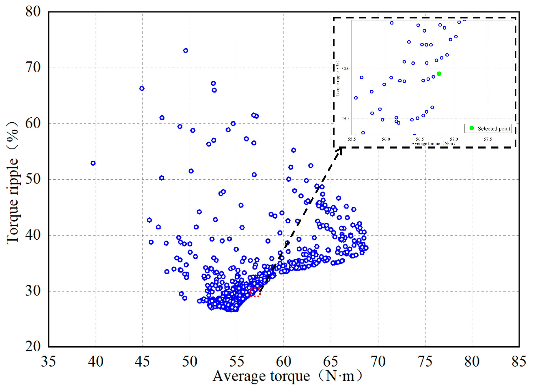
3.3. Multi-Objective Optimization of pilOPT Algorithm

The pilOPT algorithm is one of the modeFRONTIER self-created algorithms [31]. It includes various internal optimization strategies, utilizing machine learning logic to intelligently explore the design space, while combining the advantages of local and global searches, making it more precise and efficient in searching for Pareto frontiers. This article uses this algorithm for global multi-objective optimization of the remaining key parameters. The number of iterations constraint formula is defined as shown in Equation (8).
r 1000
where, r is the number of iterations.
Because the pilOPT algorithm cannot independently determine the optimality of the optimization results, it is necessary to provide a solution that meets expectations. Because excessive torque ripple can seriously affect the torque performance of the motor, the solution is to use the model with torque ripple less than 30% and maximum average torque as the best-found solution. The constraint functions for selecting the objective point are defined as Equation (9).
s . t . C 1 = max ( Tave ) C 2 = Trip 0.3 0
where, C 1 and C 2 are the constraint functions for average torque and torque ripple, respectively.
The Pareto front of the iteration result is shown in Figure 14, and the green point represents the target point, which is the point with the highest average torque when the torque ripple is less than 30%. The specific size parameters of this point are shown in Table 5.

4. Performance Analysis of Optimized Model

A performance comparison was conducted between the optimized model and proposed model 2. And demagnetization analysis was conducted on the optimized model’s permanent magnet.

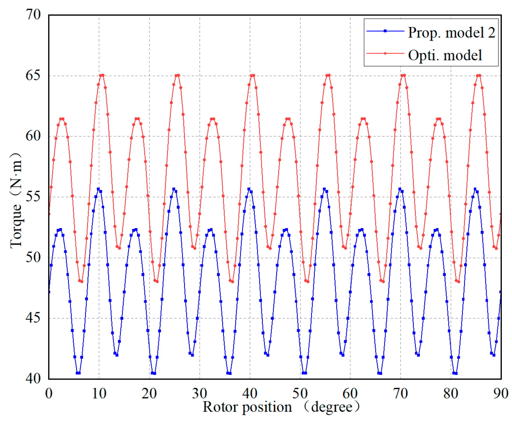
4.1. Comparison of Optimized Model Performance

After multi-objective optimization of the rotor structure of proposed model two, performance analysis was conducted on the optimized model. The torque of the optimized model exhibits a significant increase compared to that of proposed model two in Figure 15. The magnetic flux lines within the stator of the optimized model exhibit a significant increase in Figure 16a, indicating an enhanced excitation effect. The magnetic density in the internal magnetic circuit of the optimized rotor is more saturated in Figure 16b. We can see the specific performance data of the optimized model in Table 6. The optimized model has an increase of 43.85% in the RMS value of the no-load back EMF compared to proposed model two. The RMS value of no-load air gap magnetic density increased by 41.99%, the average torque increased by 18.14%, the torque ripple decreased by 5.22%, the total loss decreased by 1.35%, and the efficiency improved by 1.05%. The optimized model has improved in all aspects compared to proposed model two, indicating that the optimized model has good motor performance.

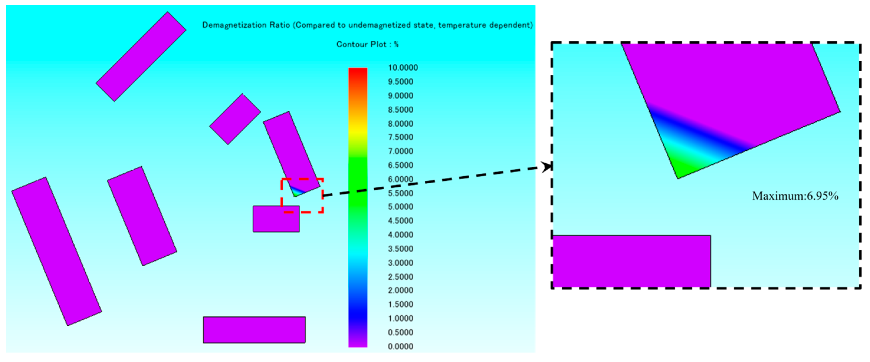
4.2. Performance Analysis of Anti-Demagnetization

Due to the use of multiple layers and different magnetization directions in the permanent magnet of the model, there may be a risk of demagnetization. Therefore, the authors carried out demagnetization analysis on the permanent magnet of the optimized model. Demagnetization analysis of permanent magnets is performed by analyzing the changes in the residual number of magnets before and after current excitation. The demagnetization ratio definition formula [32] is shown in Equation (10).
δ = 1 B r B r × 100 %
where, B r is the remanent magnetism of the permanent magnet after overcurrent, and B r is the initial remanent magnetism of the permanent magnet.
Under overcurrent conditions, the demagnetization rate of the permanent magnet of the optimized model is shown in Figure 17. Demagnetization simulation was performed under overcurrent working conditions, operating at a maximum of 10 times the rated current. The permanent magnet inside the optimized model rotor had hardly any demagnetization. When the current continued to increase to 11 times the rated current, the permanent magnet in the top magnetic barrier of the rotor of the optimized model began to demagnetize, as shown in Figure 18, with a maximum demagnetization rate of 6.95%. In a word, the optimized model exhibited good anti-demagnetization performance and can still operate stably under overcurrent conditions.

5. Conclusions

This article proposed two methods that combine Halbach array and a PMA-SynRM model with magnetic focusing effect, to improve electromagnetic torque and efficiency by increasing excitation and increasing internal magnetic saturation of a rotor. A multi-objective optimization was carried out on the rotor topology structure of proposed model two. The specific conclusion is as follows.
(1)
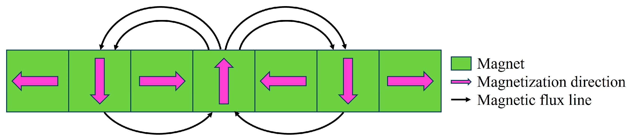
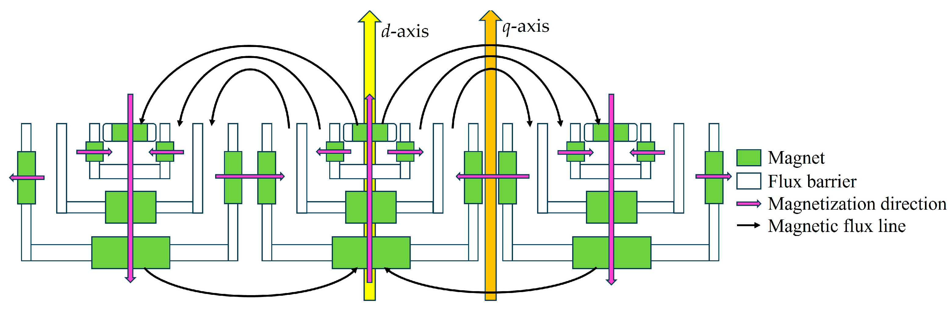
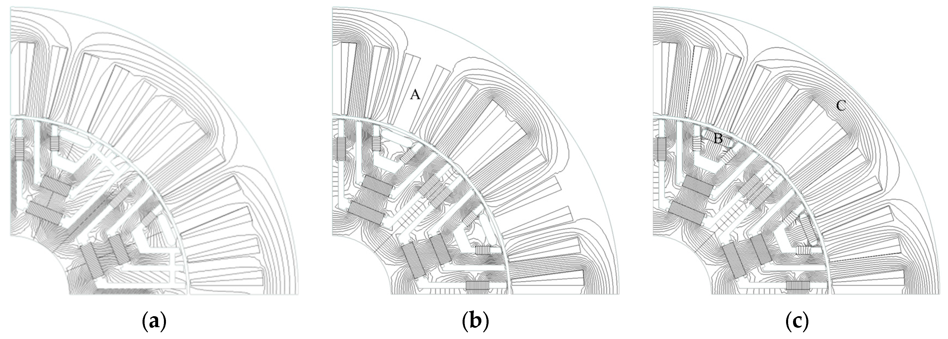
The magnetic field line distribution, air gap magnetic density and back EMF under no-load conditions were analyzed. It was proven that the magnetic focusing effect exists in the proposed model, and the excitation effect is obviously improved.
(2)
Under load conditions, proposed model two had a more saturated internal magnetic circuit than the basic model, with an average torque increase of 24.08% and an efficiency improvement of 1.45%.
(3)
After multi-objective optimization of the rotor magnetic barrier and permanent magnet size of the proposed model two, under no-load conditions, the RMS value of the air gap magnetic density increased by 41.99%, and the RMS value of back EMF increased by 43.85%. Under load conditions, the average torque was increased by 18.14%, the torque ripple was decreased by 5.22%, the total loss was decreased by 1.35%, and the efficiency was increased by 1.05% compared to the initial proposed model two.
(4)
After conducting an anti-demagnetization analysis on the optimized model, the simulation results show that the structure of the model has good demagnetization resistance and positive reliability.

Author Contributions

Conceptualization, F.X.; methodology, F.X.; software, J.Z.; validation, J.Z.; formal analysis, J.Z.; investigation, L.K.; resources, C.Q.; data curation, J.Z.; writing—original draft preparation, J.Z.; writing—review and editing, L.K.; visualization, L.K.; supervision, C.Q.; project administration, F.X.; funding acquisition, C.Q. All authors have read and agreed to the published version of the manuscript.

Funding

This research was in part supported by the Stable Funding Support for Universities in Shenzhen (GXWD20220817140906007) and the Start-up Funding for Newly Introduced Talents in Shenzhen (CA11409031).

Data Availability Statement

Data are contained within the article.

Conflicts of Interest

The authors declare no conflicts of interest.

References

  1. Wu, S.; Sun, X.; Tong, W. Optimization Design of High-speed Interior Permanent Magnet Motor with High Torque Performance Based on Multiple Surrogate Models. CES Trans. Electr. Mach. Syst. 2022, 6, 235–241. [Google Scholar] [CrossRef]
  2. Huynh, T.A.; Peng, J.X.; Hsieh, M.F.; Huang, P.W. Anti-Demagnetization Analysis of Fractional Slot Concentrated Windings Interior Permanent Magnet Motor Considering Effect of Rotor Design Parameters. IEEE Trans. Magn. 2022, 58, 8201606. [Google Scholar] [CrossRef]
  3. Zhang, Z. Design and Experimental Verification of Low Cost Ferrite PM-Assisted Synchronous Reluctance Motor. In Proceedings of the 2020 IEEE Transportation Electrification Conference & Expo (ITEC), Chicago, IL, USA, 23–26 June 2020; pp. 327–334. [Google Scholar]
  4. Bianchi, N.; Bolognani, S.; Carraro, E.; Castiello, M.; Fornasiero, E. Electric Vehicle Traction Based on Synchronous Reluctance Motors. IEEE Trans. Ind. Appl. 2016, 52, 4762–4769. [Google Scholar] [CrossRef]
  5. Lim, D.K.; Yi, K.P.; Woo, D.K.; Yeo, H.K.; Jong-Suk, R.; Lee, C.G.; Jung, H.K. Analysis and Design of a Multi-Layered and Multi-Segmented Interior Permanent Magnet Motor by Using an Analytic Method. IEEE Trans. Magn. 2014, 50, 8201308. [Google Scholar] [CrossRef]
  6. Nasr, A.; Chareyron, B.; Abdenour, A.; Milosavljevic, M. Design of a Permanent Magnet assisted Synchronous Reluctance motor using Ferrites. In Proceedings of the 2020 International Conference on Electrical Machines (ICEM), Gothenburg, Sweden, 23–26 August 2020; pp. 1758–1764. [Google Scholar]
  7. Kumar, J.; Gowtham, V.; Sampathirao, S. Comparison of Synchronous Reluctance, PM assisted Synchronous Reluctance and Spoke-Type BLDC Motor for an E-Rickshaw. In Proceedings of the 2021 22nd IEEE International Conference on Industrial Technology (ICIT), Valencia, Spain, 10–12 March 2021; pp. 172–177. [Google Scholar]
  8. Bianchi, N.; Fornasiero, E.; Soong, W. Selection of PM Flux Linkage for Maximum Low-Speed Torque Rating in a PM-Assisted Synchronous Reluctance Machine. IEEE Trans. Ind. Appl. 2015, 51, 3600–3608. [Google Scholar] [CrossRef]
  9. Ntontis, K.; Martis, C.S. An Effort to Replace Interior Permanent Magnets Rotors with Assisted Reluctance Rotors. In Proceedings of the 2022 International Symposium on Power Electronics, Electrical Drives, Automation and Motion (SPEEDAM), Sorrento, Italy, 22–24 June 2022; pp. 294–298. [Google Scholar]
  10. Zhao, W.; Zhao, F.; Lipo, T.A.; Kwon, B.I. Optimal Design of a Novel V-Type Interior Permanent Magnet Motor with Assisted Barriers for the Improvement of Torque Characteristics. IEEE Trans. Magn. 2014, 50, 8104504. [Google Scholar] [CrossRef]
  11. Wang, Y.; Bacco, G.; Bianchi, N. Geometry Analysis and Optimization of PM-Assisted Reluctance Motors. IEEE Trans. Ind. Appl. 2017, 53, 4338–4347. [Google Scholar] [CrossRef]
  12. Zhequan, W.; Dejun, Y.; Lujun, C.; Jia, F. Design of Magnetic Barrier Angle of Permanent Magnet Assisted Synchronous Reluctance Motor Based on Minimum Torque Ripple. In Proceedings of the 2022 7th Asia Conference on Power and Electrical Engineering (ACPEE), Hangzhou, China, 15–17 April 2022; pp. 1712–1716. [Google Scholar]
  13. Xu, G.; Liu, G.; Zhao, W.; Chen, Q.; Du, X. Principle of Torque-Angle Approaching in a Hybrid Rotor Permanent-Magnet Motor. IEEE Trans. Ind. Electron. 2019, 66, 2580–2591. [Google Scholar] [CrossRef]
  14. Maroufian, S.S.; Pillay, P. Design and Analysis of a Novel PM-Assisted Synchronous Reluctance Machine Topology with AlNiCo Magnets. IEEE Trans. Ind. Appl. 2019, 55, 4733–4742. [Google Scholar] [CrossRef]
  15. Amin, M.; Aziz, G.A.A. Hybrid Adopted Materials in Permanent Magnet-Assisted Synchronous Reluctance Motor with Rotating Losses Computation. IEEE Trans. Magn. 2019, 55, 8103305. [Google Scholar] [CrossRef]
  16. Ferrari, M.; Bianchi, N.; Fornasiero, E. Analysis of Rotor Saturation in Synchronous Reluctance and PM-Assisted Reluctance Motors. IEEE Trans. Ind. Appl. 2015, 51, 169–177. [Google Scholar] [CrossRef]
  17. Nobahari, A.; Vahedi, A.; Nasiri-Zarandi, R. A Modified Permanent Magnet-Assisted Synchronous Reluctance Motor Design for Torque Characteristics Improvement. IEEE Trans. Eng. Conv. 2022, 37, 989–998. [Google Scholar] [CrossRef]
  18. Diao, C.; Zhao, W.; Liu, Y.; Wang, X. Permanent Magnet Assisted Synchronous Reluctance Motor with Asymmetric Rotor for High Torque Performance. CES Trans. Electr. Mach. Syst. 2023, 7, 179–186. [Google Scholar] [CrossRef]
  19. Duan, L.; Lu, H.; Zhao, C.; Shen, H. Influence of Different Halbach Arrays on Performance of Permanent Magnet Synchronous Motors. In Proceedings of the 2020 IEEE International Conference on Artificial Intelligence and Computer Applications (ICAICA), Dalian, China, 27–29 June 2020; pp. 994–998. [Google Scholar]
  20. Yu, Z.; Yan, L.; Zhou, Y.; Liu, J.; He, X.; Aboelhassan, A. Performance Analysis of PMSM Based on Improved Trapezoidal Halbach Magnet Arrays. In Proceedings of the 2022 IEEE 17th Conference on Industrial Electronics and Applications (ICIEA), Chengdu, China, 16–19 December 2022; pp. 1267–1271. [Google Scholar]
  21. Liu, X.; Zheng, X.; Wang, X. Modeling of Uneven Air Gap Magnetic Field for Disc Planetary Permanent Magnet Machine with Segmented Gap Halbach Array. IEEE Trans. Eng. Conv. 2023, 38, 693–702. [Google Scholar] [CrossRef]
  22. Liu, C.; Sun, J.; Zhang, Y.; Shang, J. Theoretical Analysis and Structural Optimization of Ultrathin Permanent Magnet Linear Array Motor. In Proceedings of the 2023 26th International Conference on Electrical Machines and Systems (ICEMS), Zhuhai, China, 5–8 November 2023; pp. 5044–5047. [Google Scholar]
  23. Zhou, H.; Liu, Y.; Yang, C. A High-Torque Flux-Modulated Permanent Magnet Motor with Reduced Low-Order Spatial Harmonics. In Proceedings of the 2023 26th International Conference on Electrical Machines and Systems (ICEMS), Zhuhai, China, 5–8 November 2023; pp. 4749–4754. [Google Scholar]
  24. Hu, J.Q.; Jiang, R.H.; Zhu, S.S.; Liu, C.; Wang, K. Multi-Objective Optimization Design of Permanent Magnet Assisted Synchronous Reluctance Motor. In Proceedings of the 2023 26th International Conference on Electrical Machines and Systems (ICEMS), Zhuhai, China, 5–8 November 2023; pp. 3849–3853. [Google Scholar]
  25. Kim, J.B.; Hwang, K.Y.; Kwon, B.I. Optimization of Two-Phase In-Wheel IPMSM for Wide Speed Range by Using the Kriging Model Based on Latin Hypercube Sampling. IEEE Trans. Magn. 2011, 47, 1078–1081. [Google Scholar] [CrossRef]
  26. Hidaka, Y. Multi-Objective Topology Optimization Method for Hybrid-Type Motors Combining Combinatorial Optimization and Local Search. IEEE Trans. Magn. 2024, 60, 8200404. [Google Scholar] [CrossRef]
  27. Hua, Y.; Zhu, H.; Gao, M.; Ji, Z. Multiobjective Optimization Design of Permanent Magnet Assisted Bearingless Synchronous Reluctance Motor Using NSGA-II. IEEE Trans. Ind. Electron. 2021, 68, 10477–10487. [Google Scholar] [CrossRef]
  28. Hu, Y.; Li, L.; Chen, B.; Xiao, Y.; Li, X.; Shi, J. Demagnetization Analysis of a Line Start PM-Assisted Synchronous Reluctance Motor. In Proceedings of the 2021 24th International Conference on Electrical Machines and Systems (ICEMS), Gyeongju, Republic of Korea, 31 October–3 November 2021; pp. 1157–1161. [Google Scholar]
  29. Zhang, Z.Y.; Tsai, M.C.; Huang, P.W.; Cheng, C.W.; Huang, J.M. Characteristic comparison of transversally laminated anisotropic synchronous reluctance motor fabrication based on 2D lamination and 3D printing. In Proceedings of the 2015 18th International Conference on Electrical Machines and Systems (ICEMS), Pattaya, Thailand, 25–28 October 2015; pp. 894–897. [Google Scholar]
  30. Li, G. A Pearson Based Feature Compressing Model for SNARE Protein Classification. IEEE Access 2020, 8, 136560–136569. [Google Scholar] [CrossRef]
  31. Llopis-Albert, C.; Rubio, F.; Zeng, S. Multiobjective Optimization Framework for Designing A Vehicle Suspension System. A Comparison of Optimization Algorithms. Adv. Eng. Softw. 2023, 176, 103375. [Google Scholar] [CrossRef]
  32. Wang, K.; Li, J.; Zhu, S.S.; Liu, C. Novel Hybrid-Pole Rotors for Consequent-Pole PM Machines without Unipolar Leakage Flux. IEEE Trans. Ind. Electron. 2019, 66, 6811–6823. [Google Scholar] [CrossRef]
Figure 1. (a) Topological diagram of stator core structure. (b) Basic model rotor core topology structure. (c) Proposed model 1 rotor core topology structure. (d) Proposed model 2 rotor core topology structure.
Applsci 14 05253 g001
Figure 2. Halbach array magnetization method.
Applsci 14 05253 g002
Figure 3. Proposed model 2: flat, unfolded view.
Applsci 14 05253 g003
Figure 4. Vector diagram of proposed model 2.
Applsci 14 05253 g004
Figure 5. Distribution of magnetic flux lines under no-load conditions. (a) Basic model. (b) Proposed model 1. (c) Proposed model 2. A, B and C are applicable in all three models. A and C are two distinct regions in the stator and B is the topmost flux barrier in the rotor.
Applsci 14 05253 g005
Figure 6. Three models of air gap magnetic flux density under no-load conditions.
Applsci 14 05253 g006
Figure 7. Comparison of back EMF waveform over a period.
Applsci 14 05253 g007
Figure 8. Cloud maps showing magnetic flux density under load conditions for the three models. (a) Basic model. (b) Proposed model 1. (c) Proposed model 2. D and E are applicable in all three models. D and E are the magnetic circuit areas in each of the two-layers of the flux barrier in the rotor.
Applsci 14 05253 g008
Figure 9. Electrical torque of three models.
Applsci 14 05253 g009
Figure 10. Torque characteristics of the three models. (a) Basic model. (b) Proposed model 1. (c) Proposed model 2.
Applsci 14 05253 g010aApplsci 14 05253 g010b
Figure 11. Rotor topology size parameters of proposed model 2.
Applsci 14 05253 g011
Figure 12. Multi-objective optimization flowchart.
Applsci 14 05253 g012
Figure 13. Sensitivity analysis of size parameters of rotor topology structure.
Applsci 14 05253 g013
Figure 14. Multi-objective optimization scatter plot.
Applsci 14 05253 g014
Figure 15. Comparison of torque between proposed model 2 and optimized model.
Applsci 14 05253 g015
Figure 16. (a) Magnetic flux line of the optimized model under no-load conditions. (b) Magnetic flux density of the optimized model under load conditions.
Applsci 14 05253 g016
Figure 17. Demagnetization analysis of the optimized model.
Applsci 14 05253 g017
Figure 18. Demagnetization rate distribution of permanent magnets.
Applsci 14 05253 g018
Table 1. Structural parameters of PMA-SynRM models.
ItemUnitBasic Model/Prop. Model 1/Prop. Model 2
Pole/Slot/8/48
Stator outer diametermm98
Stator inner diametermm61
Rotor outer diametermm60
Rotor inner diametermm15
Air gap lengthmm0.5
Motor axial lengthmm100
Remanence of magnetT1.28
Table 2. Performance parameters under no-load conditions.
ItemUnitBasic ModelProp. Model 1Prop. Model 2
Back EMF (RMS)V113.726140.394178.605
Air gap flux density (RMS)T0.2950.4350.412
Table 3. Performance parameters under on-load conditions.
ItemUnitBasic ModelProp. Model 1Prop. Model 2
Average torqueN·m38.78442.77548.123
Torque ripple%26.68826.05931.582
PowerW6680.777304.688126.77
Total lossW513.789514.597515.822
Efficiency%92.3192.9693.65
Table 4. Range of values of rotor structure parameter dimensions for proposed model 2.
NameItemUnitOptimization Scope
PM1 lengthLM1mm4~12.5
PM2 lengthLM2mm2.5~3
PM3 lengthLM3mm5~5.9
PM4 lengthLM4mm6~7.9
PM5 lengthLM5mm3~4.4
PM1 widthDM1mm1.4~2
PM2 widthDM2mm1.4~1.6
PM3 widthDM3mm2~3
PM4 widthDM4mm2~3
Flux barrier1 widthDB1mm1~1.5
Flux barrier2 widthDB2mm1~1.5
Flux barrier3 widthDB3mm1~1.2
Flux barrier4 widthDB4mm0.5~2
Table 5. The topological structure size parameters of the optimized model rotor.
NameItemUnitValue
PM1 lengthLM1mm5.5
PM2 lengthLM2mm2.5
PM3 lengthLM3mm5
PM4 lengthLM4mm7.9
PM5 lengthLM5mm4.4
PM1 widthDM1mm1.4
PM2 widthDM2mm1.4
PM3 widthDM3mm2
PM4 widthDM4mm2
Flux barrier1 widthDB1mm1.5
Flux barrier2 widthDB2mm1
Flux barrier3 widthDB3mm1.2
Flux barrier4 widthDB4mm0.5
Table 6. Performance parameters of the optimized model.
ItemUnitValue
Back EMF (RMS)V256.926
Air gap flux density (RMS)T0.585
Average torqueN·m56.854
Torque ripple%29.932
PowerW9473.31
Total lossW508.87
Efficiency%94.63
Disclaimer/Publisher’s Note: The statements, opinions and data contained in all publications are solely those of the individual author(s) and contributor(s) and not of MDPI and/or the editor(s). MDPI and/or the editor(s) disclaim responsibility for any injury to people or property resulting from any ideas, methods, instructions or products referred to in the content.

