Article

Algorithms for Computer-Based Calculation of Individual Strand Tensioning in the Stay Cables of Cable-Stayed Bridges

by
Marija Spasojević Šurdilović
*,
Srđan Živković
and
Dragana Turnić
Faculty of Civil Engineering and Architecture, University of Nis, 18000 Niš, Serbia
*
Author to whom correspondence should be addressed.
Appl. Sci. 2024, 14(13), 5410; https://doi.org/10.3390/app14135410
Submission received: 8 May 2024 / Revised: 8 June 2024 / Accepted: 10 June 2024 / Published: 21 June 2024
(This article belongs to the Section Civil Engineering)

Abstract

:
This paper introduces algorithms for computer-aided calculation, based on a proposed computational model for stay cables, decomposed from a bridge’s structural system. These algorithms determine the necessary tension forces and corresponding deformations in the cables for individual strand tensioning using lightweight hydraulic jacks. Two tensioning methods are discussed: the first involves single-cycle tensioning with varying force intensities, while the second employs multiple cycles by applying forces of constant intensity until achieving an equalization of forces in all strands of the cable. The efficiency of the proposed procedures is demonstrated through a numerical example.

1. Introduction

A cable-stayed bridge represents a composite structural system comprising tensioned cables, compressed towers, and beams subjected to both bending and compression [1].
Owing to their favorable structural resilience, aesthetical design, and well-established construction techniques, they are widely used [2]. The development of cable-stayed bridges has been traced from 1784 to contemporary times, and the first modern cable-stayed bridge, the Stromsund Bridge, was completed in 1955 in Sweden [3]. Since the construction of the first modern bridge of this type, there has been a noticeable rise in both the number of constructed cable-stayed bridges and the lengths of their spans [4].
Over the years, cable-stayed bridges have gained significance as their characteristics have been comprehensively explored. They have recently demonstrated exceptional cost efficiency for spans ranging from the short, medium, to long lengths [5]. Consequently, research on all aspects of the design, structural analysis, construction, inspection, maintenance, damage detection, and rehabilitation of cable-stayed bridges has emerged as a contemporary and relevant focus within the field of bridge engineering [6]. The studies [7,8,9,10], among others, have significantly advanced the development of computational models for cable-stayed bridges, leading to a better understanding and design of these structures in terms of their static and dynamic performance.
Cables function as the primary vertical load-bearing and force-transmitting components of the bridge, and even minor fluctuations in cable tension can significantly impact the overall behavior of other bridge elements, such as the deck and pylon. The structural integrity of cable-supported bridges is reliant upon steel cables, which are employed to support both the bridge deck and its associated load [11]. Therefore, determining and optimizing the initial forces in the cables is of crucial importance.
Given that the determination of initial cable forces within the structural analysis is a crucial initial stage in assessing the performance of the bridge for external loads (which are not directly the subject of this study) and precedes the application of designed forces onto the cable, only a brief overview of both classical and newer methods for determining and optimizing these forces will be provided.
There are several common approaches for determining initial cable forces. In 1993, Wang et al. [12] pioneered the zero-displacement method for determining post-cable tension in cable-stayed bridges subjected to a dead load. However, this approach fails to consider the significant horizontal displacement of girders and towers when the structure is subjected to asymmetrical loading. Based on the force equilibrium approach, Chen et al. [13] developed a novel methodology for determining cable forces in cable-stayed bridges. Despite its greater efficiency compared to previous methods, this approach also overlooks the final shape of the towers and girders. The other traditional methods that need to be mentioned are the minimum bending energy method, the rigid supported continuous beam method, and the influence matrix method [14].
In recent decades, there has been an expansion of cable force optimization methods. These methods employ various mathematical optimization algorithms to efficiently distribute forces within cable-supported structures such as bridges. The primary objectives are to minimize material usage, reduce construction costs, and simultaneously enhance structural stability and safety. A detailed overview on the optimization of cable-stayed bridges is provided in a literature survey conducted by Martins, A.M et al. [15]. It is also worth mentioning the studies that have contributed to the development of methodologies and technologies for evaluating the structural condition of bridges [16], monitoring their health [17], understanding their responses to environmental factors like temperature variations [18,19], and identifying potential damage using advanced optimization techniques [20].
Throughout the staged construction of a cable-stayed bridge, cable tensioning significantly influences the structure’s development [21]. Depending on the adopted method for assembling the bridge span structure, the most delicate operation is the activation, or tensioning, of the stay cables. This process involves phased changes in the static system of the bridge structure until the final system configuration is achieved. The tensioning of the stay cables simultaneously induces prestressing in the span structure, impacting the stress and strain states of all active elements of the system at any given moment. During this operation, tensioning individual cables must not result in a loss of tensile force in other cables, while ensuring that the deformations of the span structure and pylons remain within permissible limits. The tensioning protocol, or program, specifies the sequence, required number of phases, and the magnitude of the applied tensile force for each cable in each phase. In defining the tensioning program, besides the aforementioned considerations, the applied cable system and the equipment available to the contractor are highly relevant. Given the time and labor intensiveness of the procedures of optimizing cable tensioning during installation and construction, control becomes very important [22]. The primary objective is to minimize repetitive cable tensioning and achieve the targeted cable force according to the design specifications, thereby eliminating the necessity for final cable force adjustments [23].
Generally, the tensioning of stay cables can be performed either by the simultaneous tensioning of all strands or by individually tensioning each strand. For simultaneous tensioning, powerful hydraulic jacks, known as multi-strand jacks, are used. If these large, heavy jacks can be accommodated on the construction site, despite their size and weight, it is possible to stress the cables in one pull. This process requires careful planning, precise execution, and monitoring to prevent overloading and structural imbalance, and ensuring that the bridge structure is not subjected to excessive forces too quickly. Instead of applying the full required tension in one pull, the tensioning process can be divided into smaller increments. Each increment involves applying a portion of the designed cable force, followed by monitoring and adjustments before proceeding to the next increment.
Another method of performing cable tensioning is the individual tensioning of each strand of the cable, also known as strand-by-strand tensioning. As the concept for calculating the tensioning of a stay cable strand-by-strand presented in this paper originated during the construction of a pedestrian bridge over the Nišava River in Niš [24,25], in 2003 (Figure 1), this method will be further explained.
The tensioning of cables composed of parallel strands was performed using a lightweight hydraulic jack, also known as a mono-strand jack, or a single-strand post-tensioning jack (Figure 2), which is a crucial tool utilized in the construction of stayed engineering structures. Its primary function is to apply controlled tension to a single steel strand, typically consisting of numerous high-strength steel wires encased within a protective sheath. This specialized device plays a pivotal role in the stay cable tensioning process, ensuring the success and safety of such operations.
Strand-by-strand application of tension force to a cable can be performed in a single cycle or in several cycles. Single-cycle strand tensioning, known as “Isotension,” was developed and patented by the Freyssinet Institute [27]. In short, the principle of isotension (Figure 3) can be summarized as follows [28]: The initial strand is anchored to one end of the stay cable and tensioned to a calculated force which, due structural flexibility, must exceed the desired strand force when all strands of the stay cable are stressed. Its wedge remains disengaged from the anchor block but connects to a specialized anchoring device equipped with a load cell for force monitoring. Subsequent strands undergo a similar installation process, tensioned using a mono-strand jack with an identical load cell as the initial strand. As each strand is tensioned, the force in the preceding strands decreases until load cell readings match, ensuring uniform tension distribution. Each newly tensioned strand is then anchored to the permanent anchor block. This process is repeated until all strands are tensioned to their design force. The required designed force in the cable and the corresponding deformation are determined within the structural analysis model of the bridge for a specific construction stage [29].
The other method of individual strand tensioning is multi-cycle tensioning, where each cycle involves tensioning the strands successively with the same force. The number of cycles depends on the intensity of the designed force in the strands and the adjustability of the cable’s anchorage points. With the tensioning of each subsequent strand, there is a decrease in the forces in previously tensioned strands due to the shortening of the cable axis and the design tension force in the cable cannot be achieved in just one cycle. This necessitates performing the tensioning process in several cycles, until the forces in all strands are equalized.
Although the initial design of the cable-stayed bridge over the Nišava River in Niš specified cable installation using the single-cycle tensioning method, the cables had to be tensioned using the multi-cycle tensioning method. Despite initial reluctance, the designer accepted this approach as the contractor lacked the equipment for tensioning the strands in a single cycle.
Figure 3. Isotension method [27]: (a) principle diagram; (b) scheme of installation of the parallel strand cables with the isotension method.
Applsci 14 05410 g003
In this study, algorithms are proposed for the computer-based calculation of strand-by-strand tensioning in a stay cable, discretized from the bridge’s structural system, with corresponding boundary conditions at the anchorage blocks (Figure 4 and Figure 5). The calculation is conducted based on three algorithms, where the first one (Figure 6) pertains to the single-cycle tensioning procedure (isotension), and the other two (Figure 7 and Figure 8) relate to the multi-cycle tensioning of strands. The number of required tensioning cycles depends on both the mechanical and geometric properties of the stay cable, the magnitude of the final tensioning force, as well as the displaceability of the cable anchoring points [26].

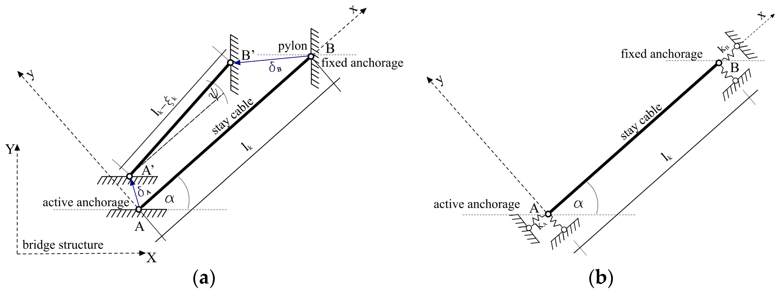
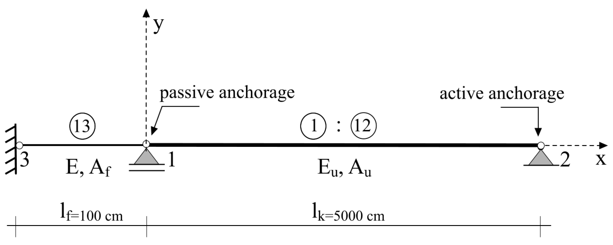
2. Modeling of Stay Cable

The model (Figure 4) represents a stay cable comprised of”n”equal parallel strands, isolated from the bridge stayed structure, where the system length is denoted as lk, the cross-sectional area of each strand as Au, and the modulus of elasticity as Eu. Due to the tensioning of the cable, the anchor nodes A and B are displaced to positions A’ and B’, where δA and δB represent the displacement vectors.
Figure 4. Stay cable: (a) disposition prior to and after tensioning, (b) mathematical model of discretized cable.
Applsci 14 05410 g004
Within the framework of the observed bridge’s structural system, the stay cable is modeled as a linear system (single member) with appropriate boundary conditions.
The following assumptions are made: the change in the distance between anchor nodes A and B (Figure 4a), or the shortening (ξk) along the system axis, is a linear function of the cable tension force Zk, the difference between the length of the straight cable axis (Figure 4) and the real, curved elastic axis due to cable sag, is considered negligible. Additionally, it is assumed that the temperature remains constant during cable tensioning.
After tensioning the cable, considering the influence of its self-weight (gk) and the force Zk applied through the active anchor A (Figure 4), the support tension forces along the cable axis will be:
R A = Z k
R B = Z k + g k · l k ξ k sin α + ψ
where RA′ and RB′ denote the support tension forces at anchor nodes A′ and B′, respectively, Zk denotes the tension force applied to the cable, gk denotes the cable self-weight, (lk − ξk) denotes the cable length after deformation, and α and ψ denote the angles of cable inclination.
For a long cable length and small cable force, the cable sag should be considered in the estimation of the cable force [30]. In that calculation, as a rule, the parallel modulus of elasticity of the cable should be introduced, for example, according to Ernst’s Formula (3). Subjected to its own dead load and axial tensile force, the cable, supported at its ends, naturally forms a catenary curve due to sag. Therefore, when utilizing a straight cable element to analyze the entire stay cable, it becomes essential to consider the sag effect, as the cable’s axial stiffness varies with changing sag. Taking into account the nonlinear sag phenomenon in inclined cable stays, employing an equivalent straight cable element with an equivalent modulus of elasticity proves beneficial for accurately representing the catenary behavior of the cable. This approach is based on the equilibrium equation of the deformed state of an infinitely flexible cable under the influence of its own weight or a uniformly distributed load along a specified direction, assuming a parabolic deformed configuration, and was developed by Ernst in 1965 [31].
The equivalent elastic modulus of a stay cable can be described by Ernst formula:
E e q = E 0 1 + γ l 2 12 σ 3 E 0
where Eeq is the equivalent modulus of elasticity, E0 is the elastic modulus of the cable, σ is the tensile stress, l is the length of the stay cable, and γ is the weight per unit length of the stay cable [32]. According to Equation (3), it can be demonstrated that the difference between the modulus of elasticity and the effective modulus of elasticity is negligible for cables of short length and significant tensile stress [5].
Over the years, a significant number of researchers [33,34,35] have been focused on improving Ernst’s formula [36] to better understand the influence of cable deformation on the external load configuration.
Assuming that the influence of the cable’s self-weight can superimpose with the effects of tensioning, considering the latter dominant influence, the cable can be represented by the model described in Figure 4. The stiffness coefficients of the elastic springs kA and kB (which simulate the shortening of the cable axis) are determined based on the actual displacements of the anchor points (nodes A and B of the model in Figure 4) in the considered bridge structural system. Furthermore, this model can be simplified while maintaining identical analytical outcomes. Such a model is illustrated in Figure 5, wherein elastic springs are substituted with a fictitious rod of length lf, a modulus of elasticity Ef, and a cross-sectional area Af.
The cable model (Figure 5) comprises ”n” rods interconnected at anchor points (1 and 2), exhibiting identical local axes (x, y, z), and equivalent boundary conditions. At the passive anchor (node 1), all strands are anchored, and the anchor is displaceable. Upon tensioning the i-th strand (i = 1, 2, ..., n), the support (anchor of the i-th strand) at the active anchor (node 2) is removed in the x-axis direction.
Figure 5. Mathematical model of stay cable for computer analysis: (a) prior to tensioning, (b) after tensioning.
Applsci 14 05410 g005
The cable (Figure 5), composed of “n” identical strands, possesses a modulus of elasticity Eu and a cross-sectional area of each strand Au. The cross-sectional area of the fictitious rod, for the adopted length lf, and a modulus of elasticity Ef = Eu, is determined based on the deformation compatibility conditions (shortening) of the cable axis within the bridge system, and can be described as:
A f = Z k l f E u ξ k
where Zk denotes cable tension force, and ξk denotes the shortening of the cable axis due to cable tensioning.
The intensities of forces Zi in the strands where tensioning occurs depend on the applied procedure: tensioning with the same force in the strands over several cycles and the procedure of successive equalization of force in the strands (isotension procedure), which is performed in only one cycle.
Analytical solutions for forces and deformations for individual tensioning of strands in one or more cycles, according to the model depicted in Figure 4, are presented in the papers [26,29].
The tension force applied to an undeformed system of a stay cable (as an external force) remains within the deformed system as a system (internal) force. In order to ensure the existence of the applied force as a system force in the undeformed system (Figure 5a), in addition to the tension force, the corresponding deformation of the strands or cable must be added. In other words, displacements that change the position of one end of the cable relative to the other must be considered.
Calculations for both options of individual tensioning of the strands in a stay cable are depicted through algorithms (Figure 6, Figure 7 and Figure 8).

3. Algorithms for Calculation

The calculation is to be performed according to the proposed algorithms and computational model of the stay cable (Figure 5). The tensioning forces and cable deformation can be calculated using any structural analysis software suitable for linear systems.

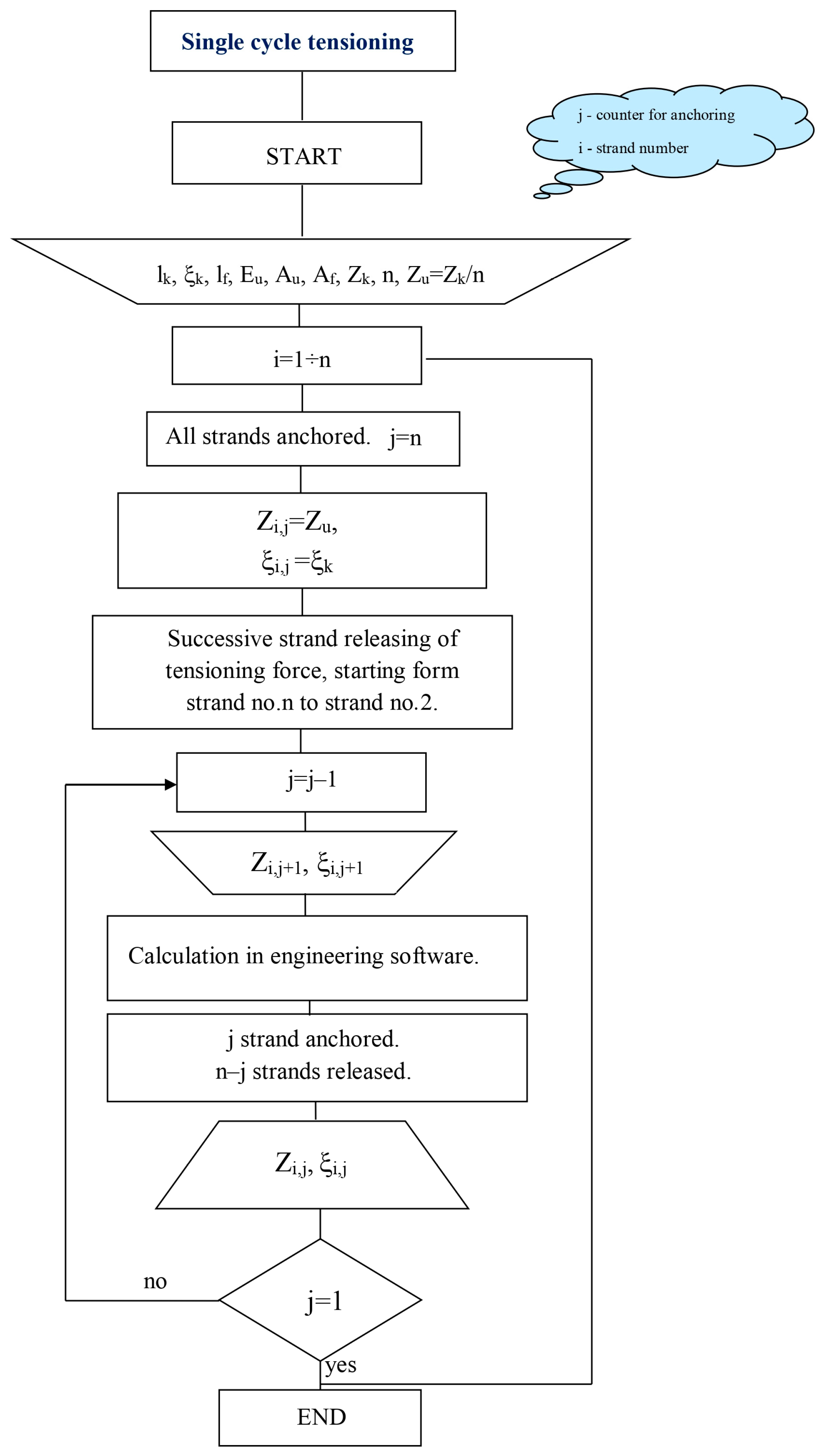
3.1. Strand Tensioning in Single Cycle

A cable of length lk composed of “n” parallel strands is tensioned by a force Zk, resulting in axis shortening ξk. All strands are anchored and tensioned with the same force Zi = Zu = Zk/n, leading to axis shortening ξi = ξk (i = 1 ÷ n).
The calculation procedure involves the successive release of tension forces in the strands, starting from the n-th (i = n) one to the penultimate one (i = 2). This is achieved by removing the support in the direction of the cable axis (node 2 of the model in Figure 5) only for the strand from which the tension force is being released. For the released (n − j) strands, the forces and axis shortenings of anchored (j) strands will be equalized. Here, Zi,j > Zi,j+1 and ξi,j < ξi,j+1, (i = 1 ÷ j). The outlined calculation procedure is depicted by the algorithm (Figure 6).
Figure 6. Flowchart of the algorithm for single-cycle strand tensioning.
Applsci 14 05410 g006

3.2. Partial Tensioning of Strands over Multiple Cycles

Individual tensioning of strands is performed in cycles (c = 1, 2, ..., m) always with the same force Zi(c) = Zu = Zk/n. In the last cycle, the forces in all strands are equalized, such that Zi(m) = Zu, Σ Zi(m) = Zk, ξk(m) = ξk, and (i = 1 ÷ n).

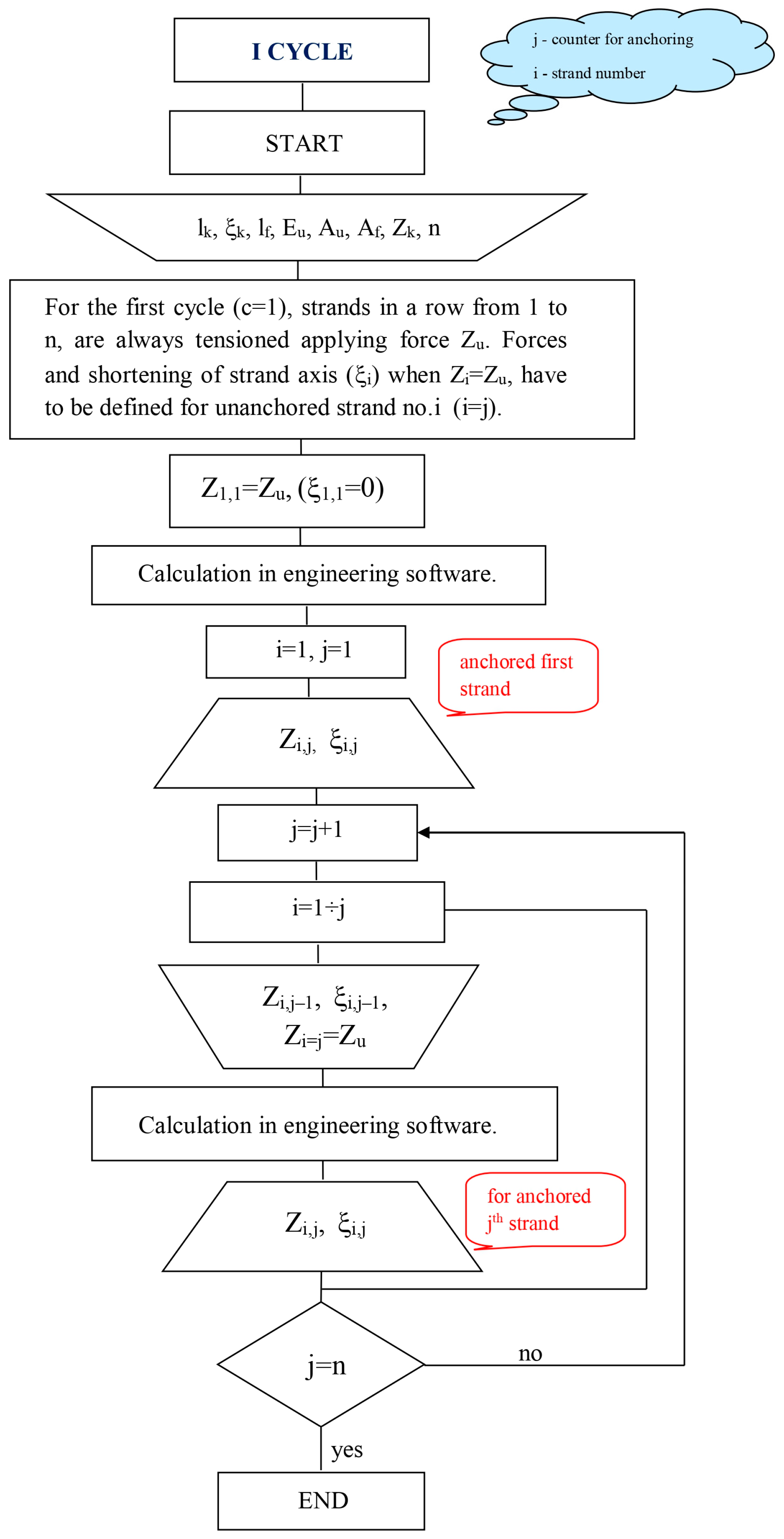
3.2.1. First Cycle (c = 1)

At the start of the first cycle, the strands are not anchored at the active anchor. The calculation procedure involves tensioning the strands successively, starting from i = 1 to i = n, after which the strand to which the force Zu is applied is anchored. For the tensioned i-th strand with force Zu, calculations are conducted for the forces in all previously tensioned and anchored strands, as well as for the i-th strand. The stress and deformation state of the cable, after the tensioned and anchored number of “j” strands, is expressed through the forces in the strands Zi,j(1), and in the cable Zk(1) = Σ Zi,j(1), and the shortening of the cable axis, or strands, where ξk,j(1) = ξi,j(1), and “i” refers to the strands for which the tension force and cable deformation are determined. The outlined calculation procedure is depicted by the algorithm (Figure 7).
Figure 7. Flowchart of the algorithm for the first cycle of multi-cycle strand tensioning.
Applsci 14 05410 g007

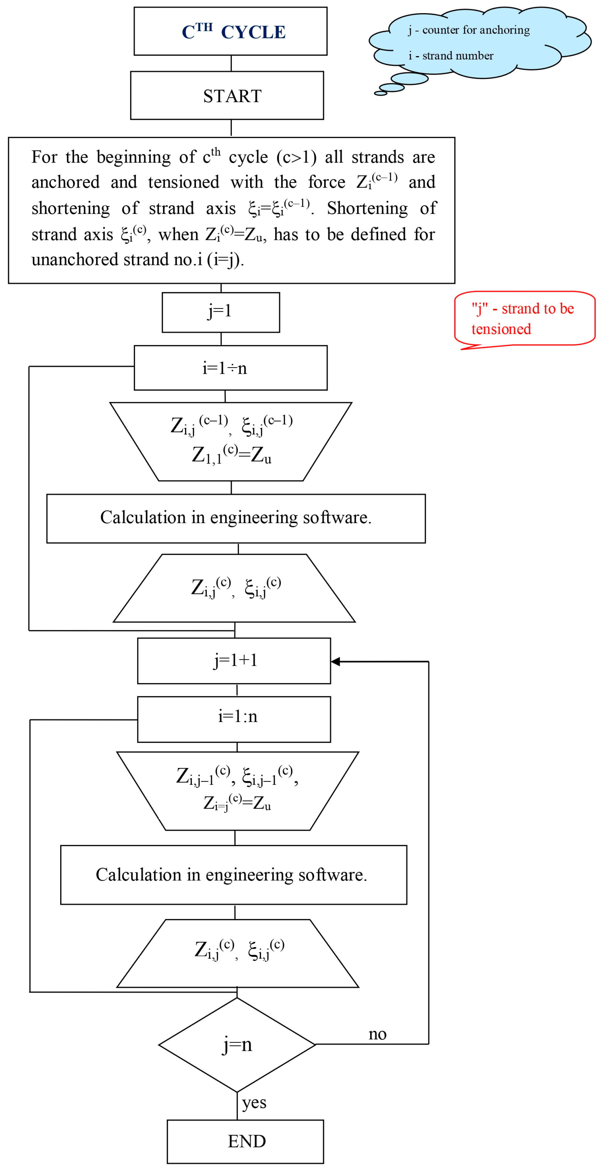
3.2.2. Subsequent (Higher) Cycles (c > 1)

At the beginning of the c-th cycle (c > 1), all strands are anchored and tensioned with forces Zi(c−1) from the previous cycle, with shortened axes ξi(c−1). The calculation procedure involves tensioning the strands successively, starting from i = 1 to i = n, after which the strand to which the force Zu is applied is anchored. For the tensioned strand i = j, calculations are conducted for the forces and shortening of axes of all strands (i = 1 ÷ n). Tensioning the last (n-th) strand concludes the c-th cycle. For i = j, the forces in the strands are Zi,j(c), and in the cable Zk,j(c), with shortened axes ξi,j(c) = ξk,j(c), where “i” refers to the strand for which the tension force and cable deformation are determined, and it can have a value less than or equal to the number of tensioned and anchored strands “j” (j = 1:n). The outlined calculation procedure is depicted by the algorithm (Figure 8). Given the defined characteristics of the cable and known Zk and ξk, the number of cycles (m) depends on the realization factor γ(c) according to relation (5), which also expresses the compatibility of stress and deformation states of the cable for each cycle:
y k c = Z k c Z k = ξ k c ξ k
In the final cycle, it is required that γ(c) = 1, meaning that the applied forces are fully realized, or 100%.
Figure 8. Flowchart of the algorithm for subsequent cycles of multi-cycle strand tensioning.
Applsci 14 05410 g008

4. Numerical Example

The numerical demonstration provided serves solely as an illustrative tool. It comprises assumed parameters, as delineated in Figure 4: specifically, lk = 50 m, α = 60°, ψ = 2°, ξk = 6 cm. Importantly, it should be noted that these parameters do not correspond to any real-world bridge scenario. The requisite data are computed based on the coordinates of the endpoints, specifically pertaining to the cable support positions, both pre- and post-tensioning of strands. These calculations are conducted within the context of the global coordinate system adopted for the bridge model under consideration. As per Equations (1) and (2), prior to the tensioning process, the tension force in the cable at the active anchor point is negligible, while it registers at 8.0 kN at the fixed anchor situated in the pylon due to the cable’s inherent weight. Following the completion of tensioning, applying the designed force of Zk = 1200 kN, the tension force in the cable reaches 1200 kN at the active anchor, whereas it elevates to 1208.0 kN at the fixed anchor. During this stage, auxiliary measures, such as a supplementary strand or other temporary supports like scaffolding, are employed to maintain the cable’s alignment.
The force applied at the jack deviates from the tensioning force within the strand under the active anchor due to the loss incurred during wedge insertion. For the cable under examination, and with a wedge insertion averaging 7 mm, the additional force by which the initial force at the jack (design force in the strand) is increased amounts to 4% of Zu = 100 kN. The attributes of the anchors and strands associated with the cable being studied align with those of cables utilized in the “SPB SUPER prestressing system”, developed at the IMS Institute in Belgrade, Serbia [37]. This system was employed in the construction of the pedestrian bridge spanning the Nišava River in Niš (Figure 1). The treated cable consists of 12 parallel seven-wire strands with a nominal diameter of 16 mm. Cable end anchorage was performed using S12/16 type anchors (normal and fixed). Cable anchorage at the pylon head was accomplished with a fixed anchor. Anchoring the cable into the bridge deck structure was performed via a normal (active) anchor, through which individual strand tensioning was performed.
The materials for the stay cable consist of sheathed strands of type EN10138-3-Y1860 S7-16 (Table 1), factory-coated with grease and encased in a hard high-density polyethylene (HDPE) coating (Table 2).
The initial weight of the cable being installed (strands + protective polyethylene tube) amounts to 121.29 + 2.17 = 17.65 kg/m. When considering additional cable components (such as anchorages, dampers, diverters distributors, steel pipe for vandalism protection, steel and polyethylene, etc.), the average weight of the cable is approximately gk = 18 kg/m.
The stay cable computational model [38], with strands of characteristics according to Table 1, Table 2 and for the fictitious rod with cross-sectional area Af, as per relation (4), is given in Figure 9.

5. Results

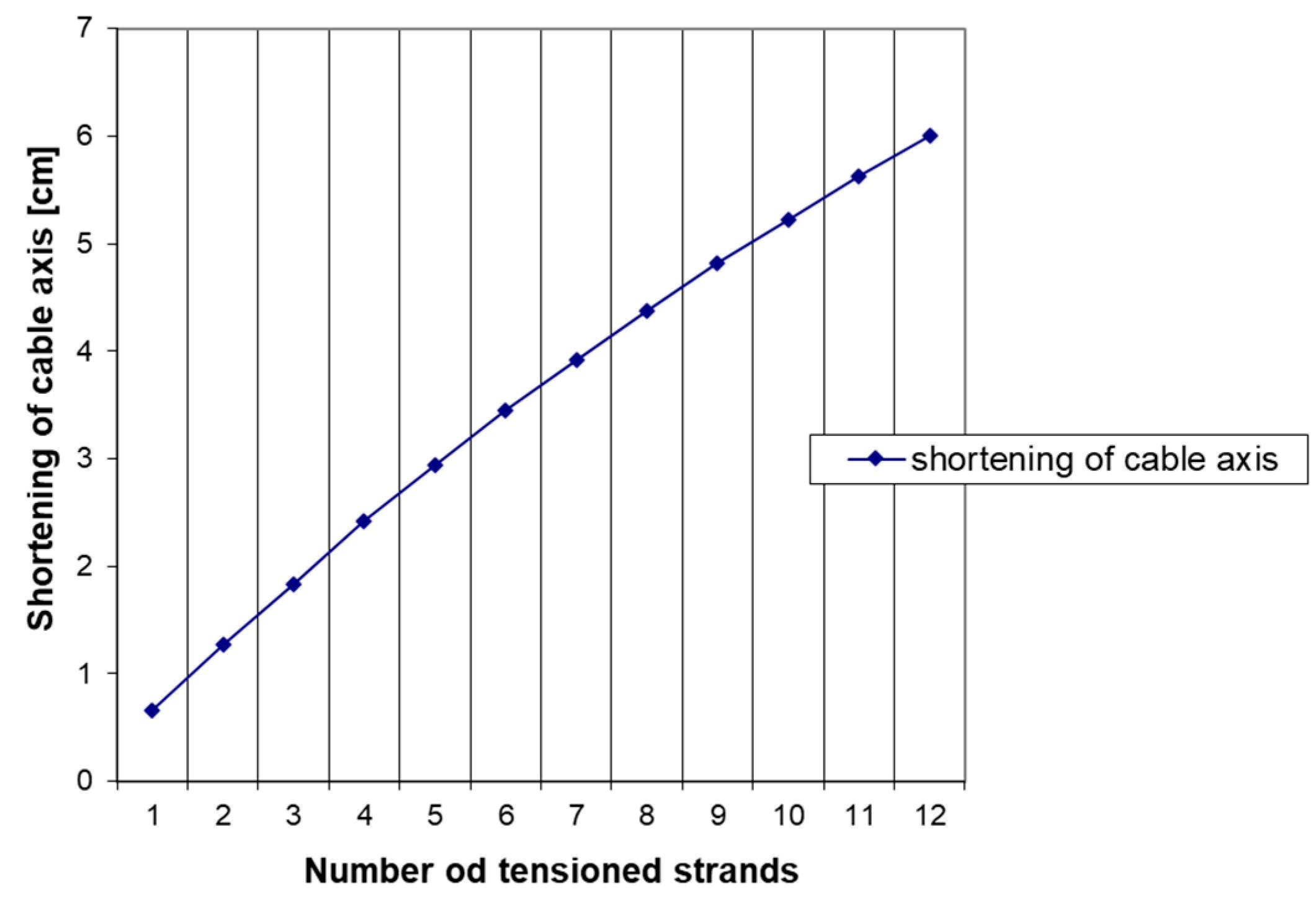
5.1. Single-Cycle Tensioning of Strands

In single-cycle tensioning, the goal is to apply forces to individual strands of the stay cable in a sequential manner, ensuring that the final tension across all strands is uniform and meets the calculated requirements. The process starts with an initial tension force and proceeds the tension across all 12 strands is equalized. In Table 3, the forces required to individually apply to the strands of the stay cable for conducting the cable tensioning procedure in a single cycle are presented. The intensities of forces to be applied are determined according to the algorithm shown in Figure 6. This implies that the calculation according to the algorithm for single-cycle tensioning starts from the condition where the cable is tensioned with the force predicted by the calculation, and when the tension forces in all 12 strands are equalized, and the deformation of the cable axis corresponds to the calculated one, according to the numerical model of the bridge. By conducting the analysis in the opposite direction from the direction of the single-cycle tensioning process, the required tensioning forces in each strand are determined for phases where the number of tensioned and anchored strands is always one less. Ultimately, the force required to be applied to the first strand for the implementation of the given procedure is obtained.
Table 3 details the forces applied to each strand (denoted as Zi) and the resulting tension forces in the cable (Zki) after each strand is stressed. For example, when the force of 131.26 kN is applied to the first strand, the cable tension force is 131.26 kN. The tension force in the cable after the last strand is stressed reaches 1200 kN. The table also shows the shortening of the cable axis (ξki) with each additional tensioned strand, indicating how the cable deforms under increasing tension.
Strand-by-strand tensioning in a single cycle is effectively illustrated through Figure 10 and Figure 11. The force in the cable after tensioning each successive strand equals the force applied to the last strand, multiplied by the total number of tensioned strands (Figure 10).
Figure 11 graphically represents the relationship between the number of tensioned strands and the cable’s deformation.
Figure 11. Shortening of cable axis as a function of number of tensioned strands.
Applsci 14 05410 g011

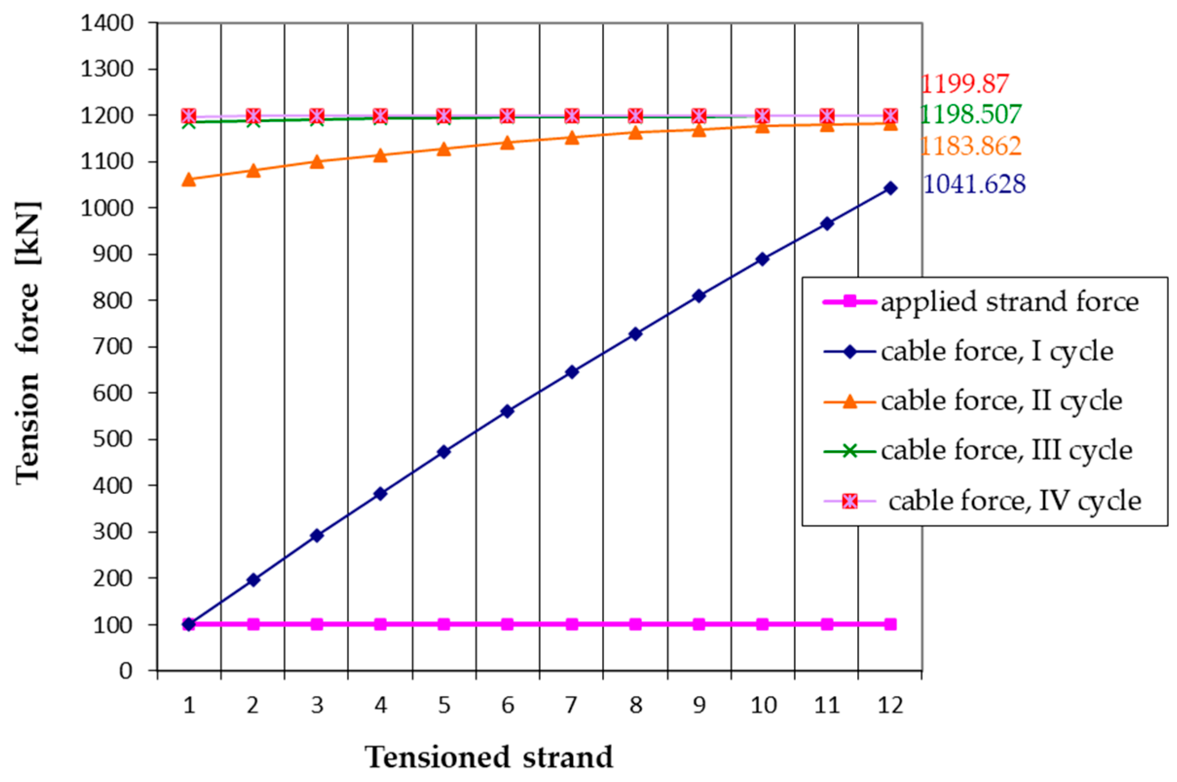
5.2. Multi-Cycle Tensioning of Strands

In contrast to single-cycle tensioning, the multi-cycle tensioning method applies a consistent force (Zu) to each strand over multiple cycles to gradually achieve the desired tension and deformation in the stay cable. The intensities of the forces in the strands for each cycle, after applying the same force (100 kN) to each strand in every cycle, are calculated according to the algorithm in Figure 7 for the first cycle and the algorithm in Figure 8 for subsequent cycles. Table 4 presents the cable force and strand forces achieved in each strand during each cycle of the multi-cycle tensioning procedure, as well as the factor of realization (γk(c)), which measures how close the actual cable force and deformation are to the designed specifications after each cycle. By analyzing this factor according to relation (5), it is determined that four cycles are necessary to achieve the designed cable force and deformation. This conclusion is supported by the incremental improvements in both tension forces and cable deformation metrics, from 86.8% after the first cycle to 100% by the fourth cycle.
Table 4 shows a gradual increase in tension forces for each strand (Zi(c)) after completing each cycle. For instance, the tension in the first strand progresses from 72.457 kN at the end of the first cycle to 100 kN by the end of the fourth cycle. The overall cable tension increases from 1041.628 kN after the first cycle to 1199.870 kN by the fourth cycle, with cable shortening stabilizing at 6.000 cm.
Figure 12 and Figure 13 depict how cable tension and deformation evolve in achieving the desired cable performance over different tensioning cycles.
Based on Figure 12 and Figure 13, it can be concluded that in each subsequent tensioning cycle, the increase in cable force and deformation occurs at a slower rate. As the curve representing cable tension force or shortening of the cable axis approaches a horizontal line, it indicates that the strand forces are becoming more equalized, and the designed values of cable force and deformation are being reached.
After the fourth tensioning cycle, the maximum deflection of the stay cable [39] amounts to:
u max = l k ξ k 8 · Z k · g k · cos α + ψ = 2.2   c m

6. Conclusions

During the installation of cables in the construction phase of cable-stayed bridges, modifications to the original plan, arising from specific situations, may pose challenges in fully adhering to established procedures. For instance, the absence of appropriate equipment for implementing the technologically advanced single-cycle cable tensioning method may necessitate resorting to the multi-cycle cable tensioning procedure. In the application of individual strand tensioning in multiple cycles, it is imperative to determine the required number of cycles to equalize forces in all strands by the end of the last cycle, and to ensure that cable force and deformation align with pre-determined design values. The algorithms proposed in this paper offer a comprehensive means of determining force intensities in the strands and the cable, as well as corresponding deformations in each tensioning cycle. This may enhance efficiency and reliability in cable installation by enabling precise control of the tensioning process at the individual strand level of the stay cable.
When implementing individual strand tensioning in a single cycle, the proposed algorithm facilitates the determination of initial tensioning force for the first strand, as well as the intensities of the forces reached in the strands during further successive tensioning, until the design target force in the cable is achieved. This approach minimizes the need for additional cable force adjustments.
However, exercising caution is crucial when employing the technological process of multi-cycle strand tensioning. Repeated wedging and unwedging may induce strand slippage, given that strand elongations decrease with each subsequent cycle, potentially leading the wedge to reach previously grooved sections of the strand at higher cycles. Additionally, it is important to note that multi-cycle strand tensioning requires more time and labor compared to single-cycle tensioning. Consequently, the single-cycle tensioning process offers an indisputable advantage in this regard.

Author Contributions

Conceptualization, M.S.Š. and D.T; methodology, S.Ž.; validation, M.S.Š., D.T. and S.Ž.; formal analysis, M.S.Š.; investigation, M.S.Š.; resources, S.Ž.; data curation, D.T.; writing—original draft preparation, M.S.Š.; writing—review and editing, D.T.; visualization, M.S.Š.; supervision, S.Ž. and D.T. All authors have read and agreed to the published version of the manuscript.

Funding

This research received no external funding.

Institutional Review Board Statement

Not applicable.

Informed Consent Statement

Not applicable.

Data Availability Statement

The data presented in this study are available on request from the corresponding author on reasonable request. The data are not publicly available due to privacy.

Acknowledgments

The results presented in this paper were the result of the investigation within the research project 451-03-65/2024-03/200095, supported by the Ministry of Science, Technological Development and Innovation, Republic of Serbia.

Conflicts of Interest

The authors declare no conflicts of interest.

References

  1. Chen, Y.; Wang, S.; Huang, K.; Zhong, J.; Cheng, H. Research on Dynamic Response of a Single-Tower Cable-Stayed Bridge with Successive Cable Breaks Based on a 3D Index. Appl. Sci. 2023, 13, 9197. [Google Scholar] [CrossRef]
  2. Zhang, X.; Peng, J.Y.; Cao, M.S.; Damjanovic, D.; Ostachowicz, W. Identification of instantaneous tension of bridge cables from dynamic responses: Strict algorithm and applications. Mech. Syst. Signal Process. 2020, 142, 106729. [Google Scholar] [CrossRef]
  3. Podolny, W., Jr.; Asce, M.; Fleming, J.F. Historical Development of Cable-Stayed Bridges. J. Struct. Div. 1972, 98. [Google Scholar] [CrossRef]
  4. Gimsing, N.J.; Georgiakis, C.T. Cable Supported Bridges Concept and Design, 3rd ed.; John Wiley & Sons, Ltd.: Hoboken, NJ, USA, 2012. [Google Scholar]
  5. Walther, R.; Houriet, B.; Isler, W.; Moia, P.; Klein, J.F. Cable Stayed Bridges, 2nd ed.; Thomas Telford Publishing: London, UK, 1999. [Google Scholar]
  6. Huang, D.; Chen, W. Cable Structures in Bridge Engineering. J. Bridge Eng. 2019, 24, 02019001. [Google Scholar] [CrossRef]
  7. Wilson, J.C.; Gravelle, W. Modelling of a cable-stayed bridge for dynamic analysis. Earthq. Eng. Struct. Dyn. 1991, 20, 707–721. [Google Scholar] [CrossRef]
  8. Wang, P.H.; Tang, T.Y.; Zheng, H.N. Analysis of cable-stayed bridges during construction by cantilever methods. Comput. Struct. 2004, 82, 329–346. [Google Scholar] [CrossRef]
  9. Shen, G.; Macdonald, J.; Coules, H.E. Nonlinear cable-deck interaction vibrations of cable-stayed bridges. J. Sound Vib. 2023, 544, 117428. [Google Scholar] [CrossRef]
  10. Fragassa, C.; Minak, G.; Pavlovic, A. Measuring deformations in the telescopic boom under static and dynamic load conditions. Facta Univ. Ser. Mech. Eng. 2020, 18, 315–328. [Google Scholar] [CrossRef]
  11. Cho, S.; Lynch, J.P.; Lee, J.J.; Yun, C.B. Development of an Automated Wireless Tension Force Estimation System for Cable-stayed Bridges. J. Intell. Mater. Syst. Struct. 2010, 21, 361–367. [Google Scholar] [CrossRef]
  12. Wang, P.H.; Tseng, T.C.; Yang, C.G. Initial shape of cable-stayed bridges. Comput. Struct. 1993, 47, 111–123. [Google Scholar] [CrossRef]
  13. Chen, D.W.; Au, F.T.K.; Tham, L.G.; Lee, P.K.K. Determination of initial cable forces in prestressed concrete cable-stayed bridges for given design deck profiles using the force equilibrium method. Comput. Struct. 2000, 74, 1–9. [Google Scholar] [CrossRef]
  14. Wang, L.; Xiao, Z.; Li, M.; Fu, N. Cable Force Optimization of Cable-Stayed Bridge Based on Multiobjective Particle Swarm Optimization Algorithm with Mutation Operation and the Influence Matrix. Appl. Sci. 2023, 13, 2611. [Google Scholar] [CrossRef]
  15. Martins, A.M.; Simões, L.M.; Negrão, J.H. Optimization of cable-stayed bridges: A literature survey. Adv. Eng. Softw. 2020, 149, 102829. [Google Scholar] [CrossRef]
  16. Xiao, F.; Hulsey, J.L.; Chen, G.S.; Xiang, Y. Optimal static strain sensor placement for truss bridges. Int. J. Distrib. Sens. Netw. 2017, 13. [Google Scholar] [CrossRef]
  17. Deng, Z.; Huang, M.; Wan, N.; Zhang, J. The Current Development of Structural Health Monitoring for Bridges: A Review. Buildings 2023, 13, 1360. [Google Scholar] [CrossRef]
  18. Xiao, F.; Hulsey, J.L.; Balasubramanian, R. Fiber optic health monitoring and temperature behavior of bridge in cold region. Struct. Control Health Monit. 2017, 24, e2020. [Google Scholar] [CrossRef]
  19. Suangga, M.; Hidayat, I.; Celine, J. Temperature effect on cable tension forces of cable-stayed bridge. IOP Conf. Ser. Earth Environ. Sci. 2018, 195, 012009. [Google Scholar] [CrossRef]
  20. Xiao, F.; Sun, H.; Mao, Y.; Chen, G.S. Damage identification of large-scale space truss structures based on stiffness separation method. Structures 2023, 53, 109–118. [Google Scholar] [CrossRef]
  21. Hou, S.; Dong, B.; Wang, H.; Wu, G. Inspection of surface defects on stay cables using a robot and transfer learning. Autom. Constr. 2020, 119, 103382. [Google Scholar] [CrossRef]
  22. Wang, L.; Zhang, Y.; Xiao, Z.; Liu, L. A tensioning control method for stay cables with super large tonnage cable force. Int. J. Struct. Integr. 2024, 15, 613–630. [Google Scholar] [CrossRef]
  23. Li, T.; Liu, Z. An improved continuum model for determining the behavior of suspension bridges during construction. Autom. Constr. 2021, 127, 103715. [Google Scholar] [CrossRef]
  24. Spasojević Šurdilović, M. Modeling and Sterss and Starin Analysis of Cable-Stayed Bridges during the Phase Formation of the Structaral System Using Temporary Supports. Master’s Thesis, Faculty of Civil Engineering and Architecture, University of Niš, Niš, Serbia, 2007. (In Serbian). [Google Scholar]
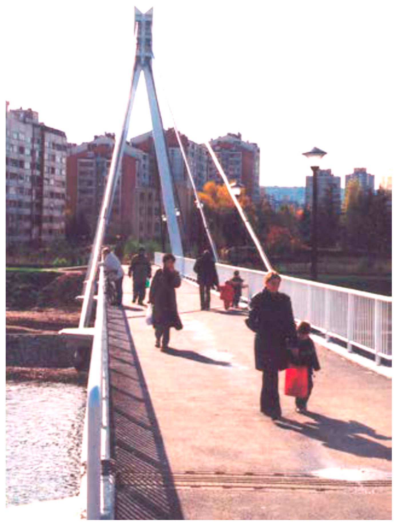
  25. Spasojević Šurdilović, M.; Spasojević, A.; Spasojević, N. Specifična problematika projektovanja i izvođenja pešačkog mosta preko reke Nišave u Nišu. In Proceedings of the Third International Scientific-Expert Conference, GNP 2010, Žabljak, Montenegro, 15–19 February 2010; Volume 1, pp. 643–648. (In Serbian). [Google Scholar]
  26. Spasojević Šurdilović, M.; Spasojević, A.; Stojić, D. Modelling of a bridge stay cable for individual strand tensioning. Građevinar 2014, 66, 549–554. [Google Scholar] [CrossRef]
  27. Freyssinet Commercial Brochure. Freyssinet HD Stay Cable. Available online: www.freyssinet.com (accessed on 20 March 2024).
  28. El Shenawy, E.A. Form Finding for Cable-Stayed and Extradosed Bridges. Ph.D. Thesis, Technischen Universität Berlin, Berlin, Germany, 2013. [Google Scholar]
  29. Spasojević Šurdilović, M.; Spasojević, A. Analytical solutions for determining tension force in strands of bridge stay-cable in isotension procedure. In Proceedings of the International Conference Innovation as a Function of Engineering Development-IDE 2011, Nis, Serbia, 25–26 November 2011; pp. 319–324. [Google Scholar]
  30. He, W.Y.; Meng, F.C.; Ren, W.X. Cable force estimation of cables with small sag considering inclination angle effect. Adv. Bridge Eng. 2021, 2, 15. [Google Scholar] [CrossRef]
  31. Croce, P. Non-linear behavior of heavy stays. Int. J. Solids Struct. 2013, 50, 1093–1107. [Google Scholar] [CrossRef]
  32. Feng, X.H.; Zhu, Z.Q.; He, X.Q. Geometrical Nonlinear Analysis for Multi-Parameters of Four Tower Cable-Stayed Bridge Based on The Bar Element Model. In Proceedings of the International Conference on Structural, Mechanical and Materials Engineering (ICSMME 2015), Dalian, China, 6–8 November 2015. [Google Scholar]
  33. Irvine, H.M. Free vibration of inclined cables. ASCE J. Struct. Div. 1978, 104, 343–347. [Google Scholar] [CrossRef]
  34. Hajdin, N.; Michaltsos, G.T.; Konstantakopulus, T.G. About the equivalent elastic modulus of elasticity of cables of cable-stayed bridges. Facta Univ. 1998, 1, 569–575. [Google Scholar]
  35. Wang, L.-Z.; Guo, Z.; Yuan, F. Quasi-static three-dimensional analysis of suction anchor mooring system. Ocean Eng. 2010, 37, 1127–1138. [Google Scholar] [CrossRef]
  36. Ernst, J.H. Der E-modul von seilen under berücksichtigung des durchhanges. Bauing 1965, 40, 52–55. (In German) [Google Scholar]
  37. The Centre for Structures and Prestressing–IMS Institute. Available online: https://institutims.rs/ (accessed on 9 June 2024).
  38. Stanković, M.; Đorđević, Đ. Stress, Software System for Static Calculation of Engineering Structures; Trion Computers: Niš, Serbia, 1991. (In Serbian) [Google Scholar]
  39. Spasojević Šurdilović, M.; Spasojević, A. Analytical Solutions for Deformations of Bridge Stay Cables. Proc. Fac. Civ. Eng. Archit. Niš 2010, 25, 207–214. (In Serbian) [Google Scholar]
Figure 1. Pedestrian bridge over the Nišava river in Niš, Serbia.
Applsci 14 05410 g001
Figure 2. Mono-strand jack usage for tensioning of the parallel strand stay cable using the ‘strand-by-strand’ technique: (a) pedestrian bridge over the Nišava river in Niš, Serbia [26]; (b) Seohae Grand Bridge, South Korea [27].
Applsci 14 05410 g002
Figure 9. Mathematical model of stay cable for numerical example.
Applsci 14 05410 g009
Figure 10. Tension force in cable as a function of number of tensioned strands.
Applsci 14 05410 g010
Figure 12. Tension force in cable as a function of number of tensioned strands in different tensioning cycles.
Applsci 14 05410 g012
Figure 13. Shortening of cable axis as a function of number of tensioned strands in different tensioning cycles.
Applsci 14 05410 g013
Table 1. Summary of geometric and mechanical characteristics of considered strand.
CharacteristicSymbolValue
Diameter (steel)d15.7 mm
Total diameter (steel + grease + HDPE)D19.1 mm
Area of strand (steel)Au150 mm2
Strand mass (steel + grease + HDPE)ms1.29 kg/m
Relaxation class-2 (low relaxation level: <2.5%)
Characteristic tensile strengthfpk 1860 N/mm2
Characteristic failure forceFpk = Au · fpk279 kN
Characteristic value of yield force at which permanent 0.1% elongation occursFp 0.1246 kN
Allowed force in strand (for considered case)0.45 Fpk12.55 kN
Modulus of elasticityE1.94 (±0.01) × 105 MPa
Table 2. High-density polyethylene (HDPE) pipe properties.
PropertySymbolValue
External diameter of pipe dp110 mm (Ddp = +1.0 mm)
Pipe wall thicknesss6.6 mm (Ds= +0.9 mm)
Mass of the HDPE pipemp2.166 kg/m1
Table 3. Applied forces in the strands, stay cable force, and cable deformation for the process of single-cycle tensioning.
StrandTension Force in Strand Zi * [kN]
123456789101112
1131.26127.633124.201120.948117.862114.929112.139109.481106.946104.526102.213100
2 127.633124.201120.948117.862114.929112.139109.481106.946104.526102.213100
3 124.201120.948117.862114.929112.139109.481106.946104.526102.213100
4 120.948117.862114.929112.139109.481106.946104.526102.213100
5 117.862114.929112.139109.481106.946104.526102.213100
6 114.929112.139109.481106.946104.526102.213100
7 112.139109.481106.946104.526102.213100
8 109.481106.946104.526102.213100
9 106.946104.526102.213100
10 104.526102.213100
11 102.213100
12 100
Zki [kN] **131.26255.266372.603483.792589.31689.574784.973875.848962.5141045.261124.341200
ξki [cm] ***0.65631.27631.86302.41902.94653.44793.92494.37924.81265.22635.62176.000
* number of tensioned strands (i); ** tension force in cable after stressing the i-th strand; *** cable shortening after stressing the i-th strand.
Table 4. Multi-cycle strand tensioning.
Strand (i)Zu [kN]Zi(c) * [kN]
Zi(1)Zi(2)Zi(3)Zi(4)
110072.45796.45099.62099.967
210075.29997.01099.71699.975
310078.06297.52199.77399.980
410080.75197.98499.82299.985
510083.37098.40099.86399.988
610085.92298.76899.89799.991
710088.41099.08999.92599.993
810090.83899.36499.94799.995
910093.20899.59299.96599.997
1010095.52499.77499.979100
1110097.78799.910100100
12100100100100100
Zk(c) [kN] **1041.6281183.8621198.5071199.870
ξk(c) [cm] ***5.2085.9205.9936.000
γk(c) ****86.8%98.66%99.88%100%
* tension force in the strand in the c-th tensioning cycle; ** tension force in the cable after completing the c-th tensioning cycle; *** cable shortening after completing the c-th tensioning cycle; **** factor of realization after completing the c-th tensioning cycle.
Disclaimer/Publisher’s Note: The statements, opinions and data contained in all publications are solely those of the individual author(s) and contributor(s) and not of MDPI and/or the editor(s). MDPI and/or the editor(s) disclaim responsibility for any injury to people or property resulting from any ideas, methods, instructions or products referred to in the content.

