Article

The Effectiveness of UWB-Based Indoor Positioning Systems for the Navigation of Visually Impaired Individuals

Department of Distributed Systems and Informatic Devices, Silesian University of Technology, 44-100 Gliwice, Poland
*
Author to whom correspondence should be addressed.
Appl. Sci. 2024, 14(13), 5646; https://doi.org/10.3390/app14135646
Submission received: 22 May 2024 / Revised: 26 June 2024 / Accepted: 26 June 2024 / Published: 28 June 2024

Abstract

:
UWB has been in existence for several years, but it was only a few years ago that it transitioned from a specialized niche to more mainstream applications. Recent market data indicate a rapid increase in the popularity of UWB in consumer products, such as smartphones and smart home devices, as well as automotive and industrial real-time location systems. The challenge of achieving accurate positioning in indoor environments arises from various factors such as distance, location, beacon density, dynamic surroundings, and the density and type of obstacles. This research used MFi-certified UWB beacon chipsets and integrated them with a mobile application dedicated to iOS by implementing the near interaction accessory protocol. The analysis covers both static and dynamic cases. Thanks to the acquisition of measurements, two main candidates for indoor localization infrastructure were analyzed and compared in terms of accuracy, namely UWB and LIDAR, with the latter used as a reference system. The problem of achieving accurate positioning in various applications and environments was analyzed, and future solutions were proposed. The results show that the achieved accuracy is sufficient for tracking individuals and may serve as guidelines for achievable accuracy or may provide a basis for further research into a complex sensor fusion-based navigation system. This research provides several findings. Firstly, in dynamic conditions, LIDAR measurements showed higher accuracy than UWB beacons. Secondly, integrating data from multiple sensors could enhance localization accuracy in non-line-of-sight scenarios. Lastly, advancements in UWB technology may expand the availability of competitive hardware, facilitating a thorough evaluation of its accuracy and effectiveness in practical systems. These insights may be particularly useful in designing navigation systems for blind individuals in buildings.

1. Introduction

Currently, blind and low-vision (BLV) people face many barriers that hinder their everyday lives. As per the International Agency for the Prevention of Blindness, 295 million individuals currently live with moderate-to-severe vision impairment, while 43 million are afflicted with blindness. Projections suggest that by 2050, the number of blind individuals may escalate to 61 million [1]. Visual impairment impacts multi-sensory perception in contrast to other sensory disorders. Studies have highlighted its notable effect on reducing mobility and hindering the capacity to move safely, comfortably, and autonomously [2,3]. BLV people, therefore, face challenges in navigating public buildings such as offices and airports. Facilitating pedestrian environments that are easier to navigate is crucial for enabling blind and visually impaired (BVI) individuals to attain the ability to move independently [4]. Indoor positioning technologies currently used have the potential to focus on contextual awareness through methods such as vision enhancement and visual substitution [5,6,7]. Electronic travel aids (ETAs) are devices crafted to identify nearby obstacles and provide details about the distance and orientation of these obstacles relative to the user [5,8]. However, most commercial solutions in these categories have not yet gained significant popularity. In the market, issues arise due to insufficient accuracy and feasibility barriers, including the necessity for physical sensor infrastructure [9,10].
Existing positioning technologies such as Bluetooth Low Energy (BLE), GPS, and Wi-Fi encounter numerous limitations that reduce their effectiveness [11,12]. In indoor settings, the utility of GPS or comparable satellite positioning systems is constrained by the necessity for line-of-sight (LoS) technology for satellite connectivity [13]. Therefore, ultra-wideband (UWB) technology is emerging as a possible solution that not only overcomes these challenges but also opens up the potential to provide a much more precise, reliable indoor location and navigation system than what is currently possible with BLE [14].
Nowadays, leading smartphones feature UWB integration to facilitate secure access and tailored user interfaces. By the year 2021, UWB technology was embedded in more than 300 million smartphones, marking an adoption rate of roughly 20%. The UWB standard is expected to be gradually incorporated into all smartphones over the next 5 to 10 years, reflecting a market potential of 1.5 billion devices annually [15]. As pointed out by MarketsandMarkets, a key catalyst for the rising preference toward UWB technology will stem from the proliferation of UWB-enabled devices. ABI Research predicts that the collective sales of all UWB-enabled devices globally will surge from 109 million devices in 2019 to surpass 1 billion devices by 2025 [16]. In total, an estimated 3.6 billion UWB-enabled devices are estimated to have been shipped worldwide by 2025. The UWB market is expected to experience double-digit growth shortly [17,18]. There are two main application domains for UWB: (1) infrastructure-free peer-to-peer solutions, such as Apple AirTags and UWB car keys for hands-free access control, and (2) infrastructure-based solutions for reliable location tracking in well-defined areas [19].
An important aspect related to navigation is the requisite accuracy, which varies based on the intended function of the localization system; for instance, in RTLS tracking patients in hospitals, an error of one meter is tolerable, while for tracking in the human body during surgery, an error of one centimeter is unacceptable. A precision of about 50 m in the context of blind people is insufficient for localizing a particular obstacle. The main advantage of UWB is the very precise location tracking within 10 cm with an acceptable position error of 30 cm [20], even in difficult indoor environments. This makes it ideal for providing real-time measurements of distance, direction, and location, while supporting two-way communication, giving it real potential in solutions dedicated to blind people. In the case of radio frequency (RF) signals, which travel at the speed of light, their penetration capabilities offer them an edge over signals reliant on line of sight (LoS), despite the latter showcasing higher accuracy within a few centimeters, as observed in LIDAR systems [21].
At present, there is a lack of standardized indoor location systems, thus demanding the selection of an appropriate solution based on the tracked environment’s characteristics and the desired level of accuracy and precision. Location tracking methods can be categorized into two groups: (1) systems that require the active participation of tracked individuals and (2) systems using passive location. The majority of location techniques belong to the category of active systems, which require tags or electronic devices worn by the tracked individual or attached to objects to determine their location. In certain instances, electronic devices may also analyze recorded data and transmit results to an application server housing a location algorithm for further processing. Conversely, in passive localization, position estimation relies on signal variance or video processing. Consequently, the tracked individual lacks electronic devices capable of inferring their position [22].
This paper focuses on the mentioned systems, which consider the primary challenge for radio frequency (RF) in intricate and ever-changing indoor environments marked by noise, multipath propagation, and non-line-of-sight (NLoS) scenarios. Most methodologies for the evaluation of indoor positioning systems (IPSs) in existing research [23,24,25,26] focus on line-of-sight (LoS) scenarios in less noise-prone environments. Therefore, a new approach has to be designed that contains an application that is portable and allows for the collection of different types of measurements and environmental data. These data have to be used to be further analyzed and evaluated in the context of the suitability of UWB-based sensors for people with disabilities to navigate around public buildings.
The presented results were obtained by tests that were carried out in various configurations, including fixed positions, using a mobile robot that follows a predefined trajectory equipped with a LIDAR system to serve as a reference point. Possible sources of interference for IPS were also assessed, including NLoS conditions, shadowing, multipath propagation, interference, etc.
The aim of this paper and research into the accuracy of beacons that are based on the fusion of BLE and UWB using two-way ranging (TWR) is to analyze and evaluate the influence of various factors on the accuracy of distance measurements. In the case of blind and partially sighted people, it is crucial to be able to guide them accurately in a variety of environments due to the number of possible obstacles along the way. The purpose of this research is to determine whether beacons have the potential to be integrated into the navigation systems currently in use, thereby facilitating the needs of BVI individuals. The obtained results will be used to assess the feasibility of using this solution in advanced navigation systems for blind and visually impaired people.

2. Related Work

Visually impaired people face challenges in terms of walking near objects, lack confidence due to limited mobility, and have to memorize directions as they are impossible to note in real time. Although Braille is a universal solution, its limitation lies in the fact that it cannot be used as a guidance tool [27]. Despite aiding visually impaired individuals in comprehending their surroundings, Braille systems do not assist them in navigating paths or avoiding obstacles [11].
In an attempt to overcome the problem of information acquisition by visually impaired people, the authors of [28] presented a method that relies on acoustic feedback and a triboelectric nanogenerator. The assistive device is described as a fingertip-inspired interactor (S.R.F.I.) [29]. It assists a blind person through its structure, recognizing Braille letters, and providing the user with high-quality audio information. On the other hand, a portable, voice-activated Braille-based feedback instrument called “Voice-Activated Braille” helps to provide information about specific characters to a visually impaired person [30].
Providing effective and accurate directional feedback in an electronic navigation aid for people who are blind is a challenging task. The researchers in [31] presented a tactile compass that continuously guides a person by giving directions via a pointing needle. Two laboratory experiments in which the system was tested showed that the user could reach the target with an average deviation of 3.03°.
Smart canes assist visually impaired individuals navigate their environment and recognize what appears in front of them, both large and small, which cannot be detected and identified with ordinary canes [32,33]. The walking stick detects an obstacle, and the microphone emits sound in the smart system. The cane also helps detect whether the environment is bright or dark [34]. Walking navigation systems using the Internet of Things and cloud networks are also proposed for indoor use [35]. The smart cane navigation system consists of a built-in camera, integrated microcontrollers, and acceleration sensors that send audio messages. The navigation system uses a cloud service that helps the user navigate from one point to another. The system detects nearby objects and alerts users through a buzzer and sonar. Cloud services retrieve the staff’s position and the route to the destination, transmitting these data from the Arduino Wi-Fi board to the cloud. Using a Gaussian model, the system estimates the position based on triangulation. The cloud service is connected to a database storing the shortest, safest, and longest paths. Distance is calculated using sound and echo emissions, which is a cost-effective method, and a text-to-audio converter notifies users about potential obstacles [36].
Another indoor navigation system proposal, based on an augmented cane system, offers real-time guidance by exploring the physical indoor environment using a micro-navigation system. The solution relies on the interaction of several components. The main components of this system are thermal mapping cameras and an application that makes indoor navigation more reliable and accurate. The whole system captures infrared signals to ensure correct navigation [33].
An alternative proposed solution is based on infrared light-emitting diodes (IR LEDs) and is suitable for generating periodic signals indoors. The drawback of this approach is that there has to be a “line of sight (LoS)” between the IR LEDs and the detectors. Moreover, it is a short-distance area communication technology. In [37], a “portable mid-range positioning system” using IR LEDs was developed for the visually impaired. The system consists of different types of methods: ultrasonic “time of flight (ToF)” and infrared intensity. The ultrasonic TIF structure consists of an ultrasonic sensor, beacon sensors, and infrared LED circuits. The receiver includes an ultrasonic, infrared, and geomagnetic sensor, as well as a signal processing module.
Another navigation system concept using an RGB-D (Red, Green, Blue, and Depth) sensor has also been under development in recent years. The RGB-D camera offers area-based ground segmentation, and the RGB sensor also provides color and object detection. In this solution, the user interface is provided via audio map details and audio cues or guidance [38,39].
A different approach is to use the cellular networking framework that allows mobile phones to connect to other people. The authors of [40] suggest that a simple way to locate mobile devices is to use Cell ID, which works in the majority of networks. Some studies [41,42] propose a hybrid method using a combination of wireless local area networks, Bluetooth, and communication networks to enhance the performance of positioning indoors. However, such tracking is unstable and prone to substantial navigation errors due to the presence of towers and radio signal interference.
As people who are visually impaired or blind are more sensitive to hearing than others, a natural approach to navigation systems has been developed that sends warnings by voice and vibration [43,44]. Depth sensors produce images typically interpreted by individuals through vision and tactile feedback. These systems convert spatial data into sound, leveraging sound’s precise guiding capability. Many methodologies in this domain draw inspiration from audio surrogate devices, which encode visual scenes captured by a video camera and generate sounds as an auditory representation referred to as a “soundscape” [45,46]. Rehri et al. [47] introduced a system that enhanced navigation without visibility, employing a guidance system based on the distinct advantage of virtual auditory guidance over spatial language.
In [48], an image recognition method for blind people using sound was presented, offering a straightforward yet efficient approach to perceiving the world through auditory cues. However, as image complexity escalates, image recognition via auditory processing becomes challenging. Initially, the sound is eliminated using Gaussian blurring. Subsequently, image edges are filtered by identifying gradients. In the third step, non-maximum suppression is employed along the contours of the image edges. Thresholding values are then determined utilizing an edge detector. Once complete edge information is acquired, a sound is generated.
Voice-controlled navigation systems provide alerts about the user’s current position and travel directions [49,50,51]. The challenge with these types of systems is that they are unable to detect and warn of obstacles [51,52]. One of the indoor navigation systems that applies a microcontroller for obstacle detection and a feedback system that uses voice donor technology to warn users of obstacles is the Roshni system [53,54]. The user position in Roshni is identified using sonar technology, which is used to mount ultrasonic modules on the ceiling. Roshni is portable, can be moved to any location, and is not influenced by variations in the environment. It requires a precise map of the building’s interior, which restricts it to navigating inside.
Systems based on ultrasonic sensors usually consist of a built-in microcontroller with synthetic speech playback and a personal device that navigates users to their destination [55]. These systems use the principle of high-frequency bouncing to locate obstacles. Verbal instructions or directions are provided in vibrotactile form to reduce the difficulty of navigation. A limitation of such systems is that ultrasonic signals are blocked by walls, resulting in less accurate navigation [56]. Ultrasonic sensors first receive visual cues and then transform them into acoustic feedback. These systems can reduce the amount of learning required to use a white cane. However, the problem lies in the global identification of the user’s location [57].
RFID (radio frequency identification) is yet another category of wireless technology used to aid visually impaired people’s activities. This technology is based on the “Internet of Things (IoT)” paradigm via the physical layer, which assists visually impaired people in perceiving their surroundings by implementing sensors in their environment. The limited communication range means that this RFID technology cannot be applied to the spatial extent of the surrounding landscape. An RFID-based indoor navigation solution for the elderly and visually impaired [58] assists people with disabilities by enabling them to navigate independently in enclosed spaces. The aim of developing this concept was to address the challenges of indoor navigation, considering the accuracy and dynamics of different environments. The system consists of two localization and navigation components, a server and a wearable module containing a built-in microcontroller, ultrasonic sensor, RFID, Wi-Fi, and voice control modules. The system takes 0.6 s to find an obstacle. A different RFID-based map-reading system [59] provides solutions for visually impaired people to navigate in public places using a grid of RFID tags, Bluetooth, a cane RFID scanner, and a smart personal digital assistant. The map-reading system incurs relatively high costs due to its hardware components, and its reliability is compromised in high-traffic areas.
Wireless network-based solutions for indoor navigation and positioning encompass diverse approaches, including communication networks, Bluetooth, UWB sensors, Wi-Fi networks, etc. [60,61,62]. Cruz and Ramos [63] proposed a 3D navigation system utilizing Bluetooth technology. Another approach, outlined in [64], combines Bluetooth beacons with Google Tango.
UWB and Bluetooth Low Energy share many common features, such as the ability to track assets. However, UWB is known for its greater accuracy than BLE. This factor is due to the difference in the method used in individual technologies; while UWB determines the location of an object using ToF, BLE locates devices using RSSI [65], which estimates the location based on the strength of the signal emitted by the device. However, in versions greater than or equal to BLE 5.1, this level of accuracy can also be achieved using algorithms such as angle of arrival (AoA) [66,67,68].
The above-described technologies are particularly beneficial for blind and visually impaired people, helping them to navigate their environments with greater confidence and independence. Technology is evolving and enhancing how BVI people communicate with the world more confidently. There are no absolute advantages or disadvantages to technology. The key is to look at usage scenarios and specific support needs. Whether it is UWB, Bluetooth AoA, geomagnetism, Wi-Fi, or even GNSS, they only provide a solution to the set requirements. Which solution to choose cannot be determined by simply looking at certain technical indicators; therefore, more detailed analyses regarding measurement accuracy in different environments and different scenarios are required.

3. Methodology

The methodology of the conducted research on the accuracy of beacons based on the combination of BLE and UWB using two-way ranging (TWR) includes a series of experiments aimed at analyzing and assessing the influence of different factors on the precision of measurements. The methodology employed both static and dynamic scenarios, drawing inspiration from the natural surroundings of blind people [69]. We considered the impact of the phone’s position, the CameraAssist option in the mobile app, LoS and NLoS conditions, and the various obstacles in the real environment. The accuracy measurement was based on LIDAR located on the JetRacer mobile platform as the LIDAR accuracy is closest to the accuracy declared in UWB systems [70].

3.1. UWB-BLE Beacons

One of the most well-known use cases of UWB is beacons, or “reflectors”, small pieces of hardware that act as data transmitters. Beacons emit radio wave signals to locate a smartphone within a specific radius. In this way, they function as signal emitters and smart devices as receivers. For such actions to take place, the user must download the application and authorize communication with a mobile phone [71].
Using two different wireless networks—BLE and UWB—creates an improved spatial awareness solution. The BLE part provides an energy-efficient method for detecting the presence of nearby devices through initial passive proximity detection and then activates UWB ranging [72]. When a nearby object is detected, the BLE method launches the UWB and then generates data, which are used to ascertain both the location and the direction of the object. In turn, the UWB part provides precise location based on broadband coverage.

3.2. Mobile App and API Apple U1 Interface

For the purposes of this research, a mobile application with a graphical interface was developed, tested, and adapted to specific use cases. Beacons, when found by the application, appeared one by one in the user’s GUI. Depending on the specific use case, the mobile application enables the following features:
  • Providing constant values during a specific test that are to be saved in the database, e.g., distance measured by tape or voltage supplied to the beacon during the test;
  • The ability to select one beacon from a drop-down list or more beacons, taking into account their location in relation to the phone;
  • Each beacon was displayed using its unique UUID and the current and updated distance value;
  • Saving to the database using the “Start Recording” switch button—recording all incoming measurements from the previously selected beacon until the button is disabled, or using the “Send Data to Server” button, which allows for a single measurement to be sent and saved in the database from a selected moment in time;
  • The “Export to CSV” button allows the user to download data from the database in CVS format;
  • An extension of the “Export to CSV” button is the “Select Export Date” button, which allows the user to select the starting date from the calendar view from which they would like to export data;
  • It is also possible to disconnect all beacons using the “Disconnect All” or select the “Disconnect” button located next to each of the found beacons—it stops the process of distance updating.

3.3. Measurement Methods

IPS measurement algorithms can be generally categorized into four main types based on their fundamental principles, namely proximity detection signal, time, and angulation, as shown in Table 1. TW-ToA (two-way time of arrival), ToA (time of arrival), AoA (angle of arrival), TDoA (time difference of arrival), and RSSI (received signal strength indicator) are commonly used with UWB in the literature (see Section 2). The method of determining the distance between two nodes is known as ranging. The measured distance is then analyzed to estimate the location, a process referred to as positioning [73,74].
Implementation should always use the IEEE 802.15.4z double-sided two-way ranging (DS-TWR) algorithm, which is designed to eliminate the need to synchronize clocks between both devices. By using DS-TWR measurement, potential clock drifts are eliminated, and both sides calculate the distance measurement without having to transmit the measured distance from one device to the other [75,76].
The proposed solution uses ToF (time-of-flight) measurements to calculate distance derived from the duration the signal takes to travel from the mobile phone to a single tag and back. The initiator starts by sending a survey message to this tag. The responder answers and dispatches the delay of the response (Treply1) to the initiator. The initiator sends a second poll message and reports the response latency (Treply2) to the responder and the total round-trip time for the first message exchange (Tround1). The respondent now calculates the final distance using the specified distance Equation (1). In the last (optional) message, the respondent sends the measured distance (d) or the time of the second round trip (Tround2) [77].
The total propagation time estimation can be accomplished through the TW-ToA technique, which is expressed as follows:
d = T r o u n d 1     T r o u n d 2 T r e p l y 1     T r e p l y 2 T r o u n d 1 + T r o u n d 2 + T r e p l y 1 + T r e p l y 2   c  
where Tround1 and Tround2 are the bidirectional return time; Treply1 and Treply2 are the response time of the initiator and responder, respectively; and c is the speed of light.
For accessing heading information even when the beacon is beyond the phone’s field of view, it is advisable to utilize the Camera Assist functionality integrated with Apple’s ARKit [78]. This function combines ARKit’s spatial awareness with nearby interaction to increase the accuracy of a nearby object. This feature uses the IMU’s (inertial measurement unit) camera and sensors to expand the device’s perceptual field, thus allowing it to indirectly “see” the transmitter [79]. Camera Assist becomes imperative on iPhone 14 and subsequent models due to Apple’s decision to decrease the count of UWB antennas on these devices. Consequently, orientation computation solely relies on sensor fusion, amalgamating data from the inertial measurement unit (IMU) and camera sensors [78].

3.4. Subject of Research and System Analysis

The measurement system consisted of the following modules:
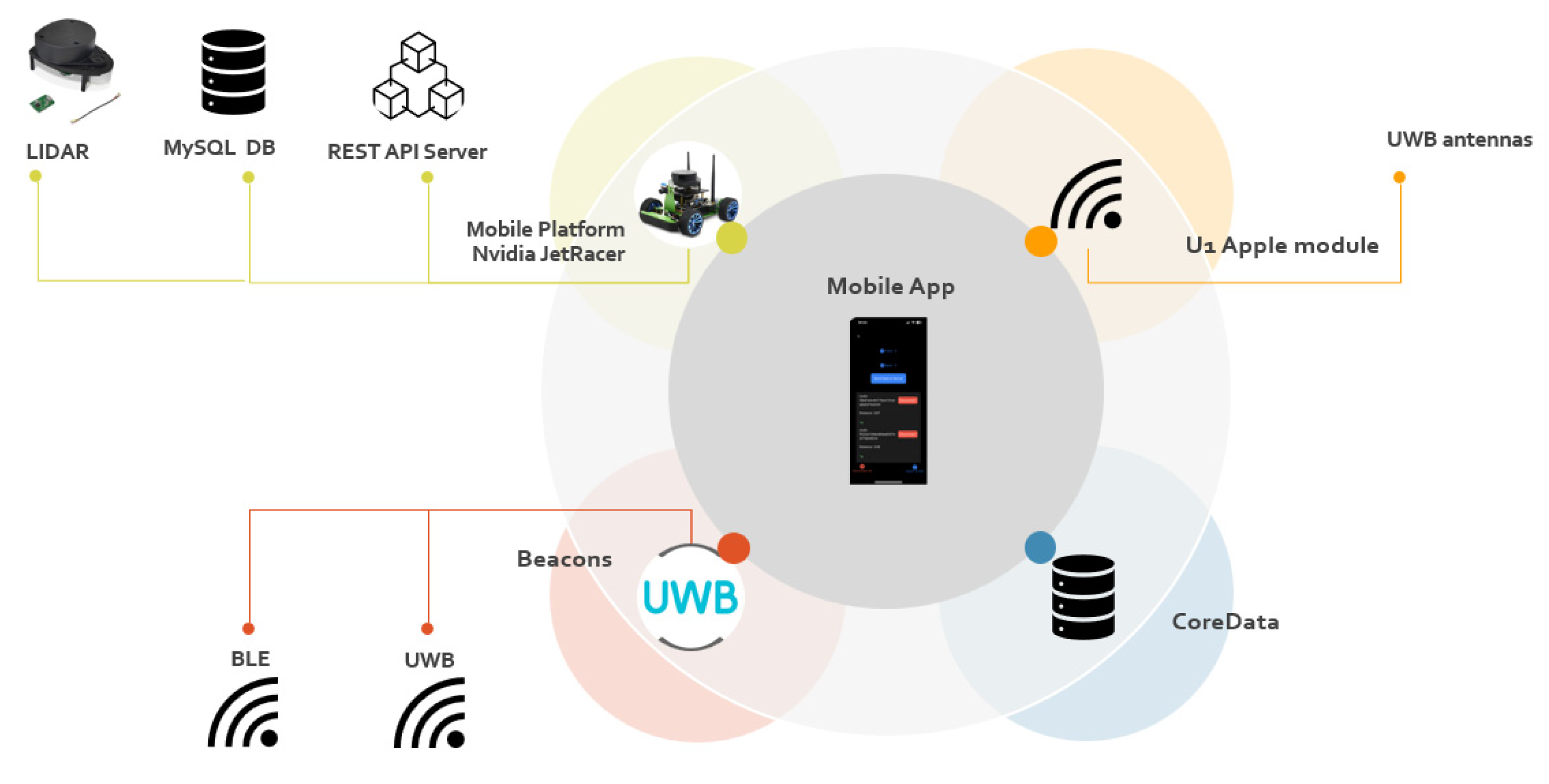
  • A set of UWB beacons based on TWR technology;
  • A phone with a designed mobile application dedicated to iOS (an iPhone 13 with U1 chipset was used in this research) enabling distance measurement using UWB beacons. The mobile application enables entering additional information about the environment, such as the measured distance using a measuring tape, or turning on/off system options, e.g., CameraAssist;
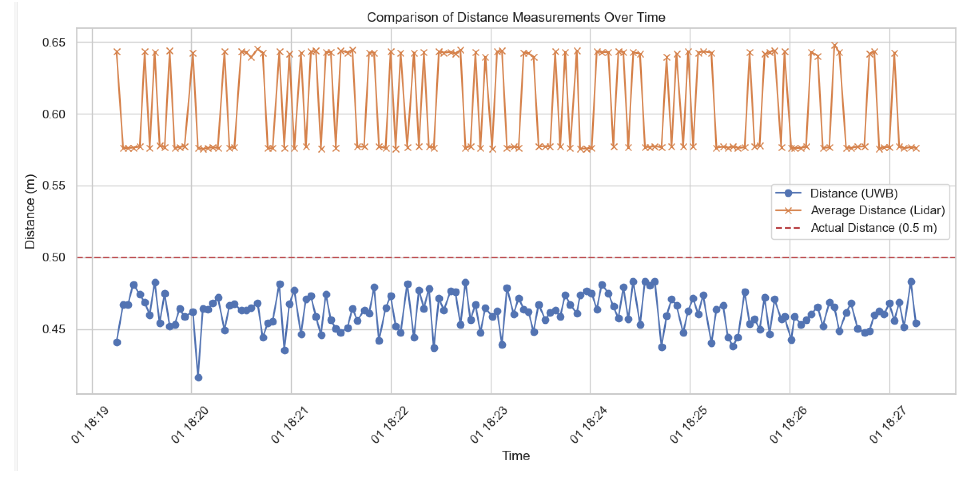
  • The reference system used in this study was the JetRacer mobile platform equipped with LIDAR, in two main cases, static and dynamic;
  • A REST API server enabling communication between the mobile application, the JetRacer platform, and the MySQL database;
  • Two databases—CoreData (collecting data when the mobile platform was not involved in the measurements) and MySQL (collecting data during dynamic tests using the Jetracer platform); the databases collected distance measurements as well as environmental information.
  • The diagram of the measurement system used in this research is shown in Figure 1.
  • In addition, the following elements were used to conduct the research:
  • GTEM (Gigahertz Transverse Electro Magnetic) cell for simulating LoS/NLoS conditions. GTEM is the chamber that simulates free-space conditions for electromagnetic wave propagation and is utilized to test the electromagnetic interference and immunity of electronic devices. Overall, GTEM cells are valuable tools in the field of electromagnetic compatibility, providing a convenient and efficient way to conduct testing in a controlled environment;
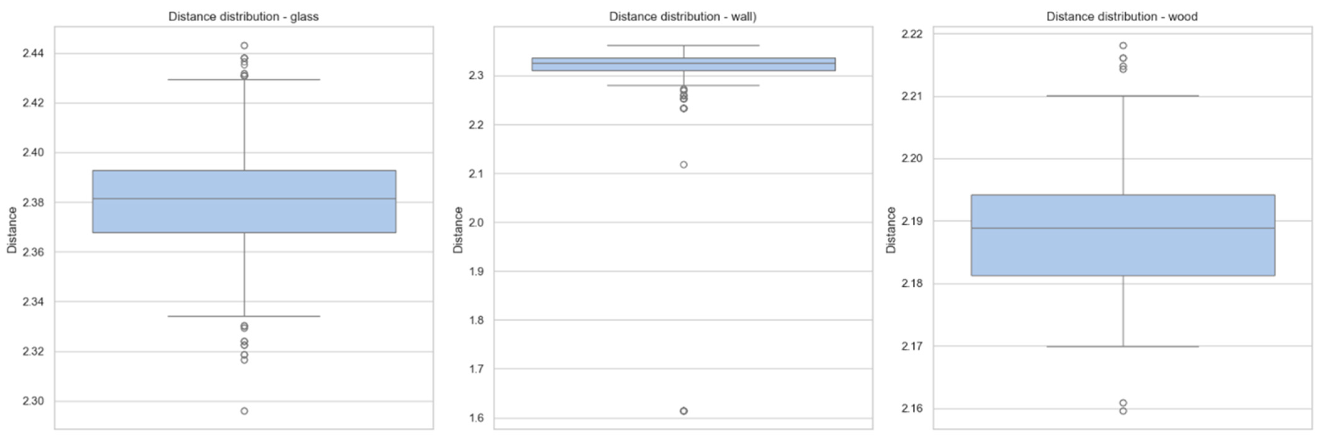
  • Various obstacles such as concrete walls, glass walls, and wooden doors;
  • A designed test environment, which consisted of rooms in a residential building, to best replicate the everyday situation; a snapshot of the test room using the SLAM (simultaneous localization and mapping) algorithm is presented in Figure 2.

3.5. Experiment Plan

In both the static and dynamic variants, the beacons were in fixed positions in the test room. The dynamic element was the JetRacer mobile platform with a built-in LIDAR and an iPhone 13 with an application to perform measurements using BLE and UWB. The iPhone was placed on the platform, so it changed the position while the car was moving. Fixed beacons were used for transmission and mobile units for reception. Static and dynamic results were compared, as well as the accuracy of measurements obtained using the mobile application with LIDAR measurements located on the JetRacer mobile platform.

3.5.1. Influence of Phone Position

UWB beacons were placed in fixed positions in the test environment, and then distance measurements were carried out using a mobile application from different phone positions (vertical and horizontal). Measurements were carried out following the experiment plan, recording all necessary parameters, such as the phone’s position, the distance between the phone and the beacon, mobile application settings, etc. The accuracy of the measurements for different phone positions was compared and analyzed.

3.5.2. Impact of CameraAssist

Measurements were taken with CameraAssist enabled and disabled in the mobile application, and the measurement accuracy for both settings was compared. The measurements were performed without and with interference. A wooden door was used as an obstacle.

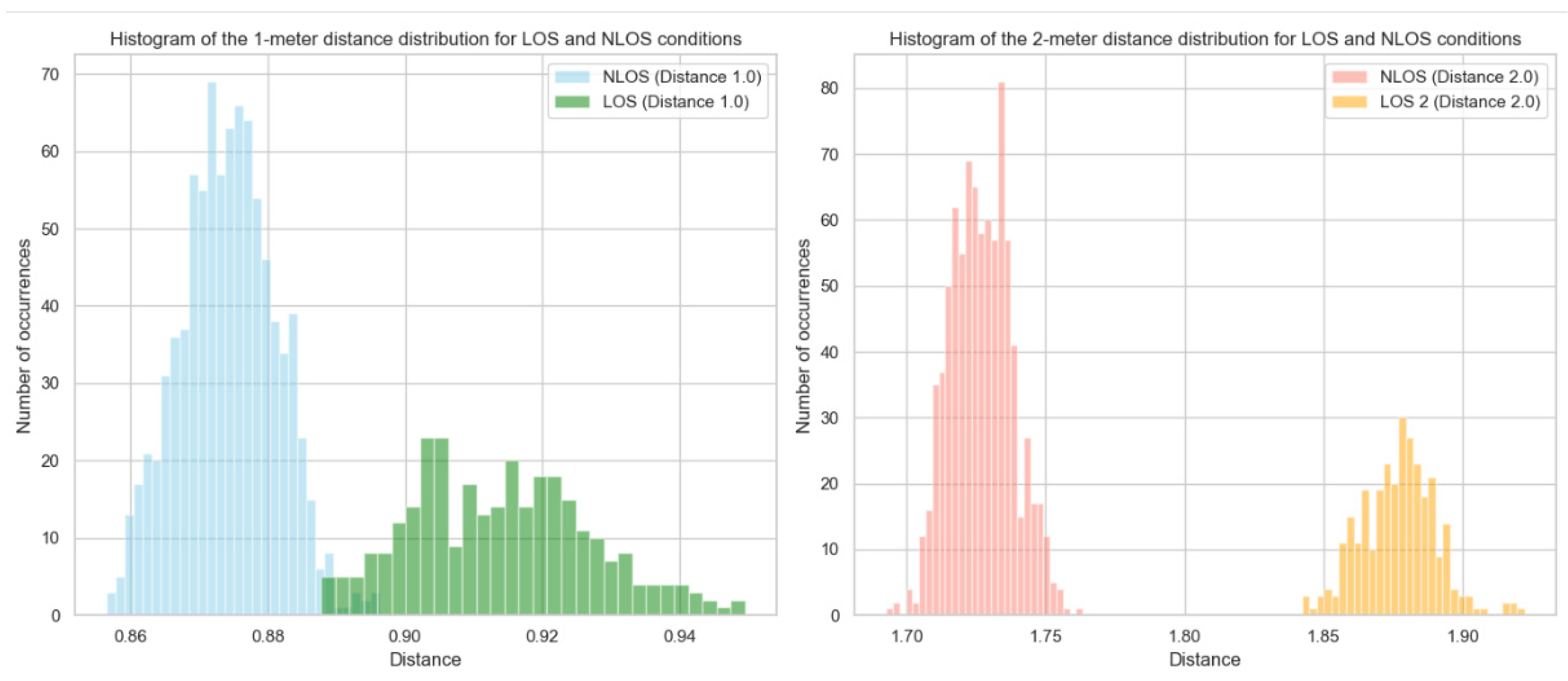
3.5.3. Impact of LoS/NLoS Conditions

Measurements were performed using a GTEM cell, simulating LoS/NLoS conditions. Additionally, tests of the influence of the supplied supply voltage on the measurement accuracy were also carried out in the GTEM chamber. Then, in a further stage, measurements were taken with various basic obstacles occurring in the real environment (concrete walls, glass walls, and wooden doors), and all cases were analyzed and compared.
Measurements were conducted over a duration of 300 s for each data point, yielding aggregated outcomes for each specific use case. During the static case, this extended measurement period (300 s) allowed us to average out short-term variations and noise, providing a more reliable assessment of the UWB beacon’s performance under stable conditions. It allowed for the collection of a significant number of samples, which improved the statistical reliability of the measurements. In all cases, research was carried out, and use cases were selected by analyzing those proposed in previous studies. The inspiration to carry out tests under static and dynamic conditions was derived from [80], which evaluated the performance of UWB in varying environmental dynamics. The precision and accuracy were assessed based on the x, y, and z positions, revealing divergent precision across the axes. The impact of beacon positioning and antenna range was thoroughly analyzed in [81], where significant differences in measurement were attributed to both antenna placement and the model of the equipment used [82]. Measurements related to the supplied energy were introduced in [83], which sought a compromise between energy consumption and the accuracy and precision of distance measurement. Distance measurement errors for devices with a low-power implementation were found to exhibit a bias and standard deviation that were at most 12 cm higher in line-of-sight propagation, and a spread 2–3 times greater in non-line-of-sight conditions compared to devices with typical power consumption. UWB has a substantial potential to reject multipath interference signals; however, NLoS issues still form the basis of many studies [84,85], and assessing their impact is a key element before implementing a UWB beacon-based localization system.
Based on these considerations, we divided the evaluation indicators into three categories:
  • Accuracy of the device;
  • Durability/reliability of the device;
  • Adaptability to a dynamic environment.
Accuracy pertains to the deviation in distance (or error) between the estimated location value of the system and its true location value. The durability of navigation devices denotes their reliability in consistently delivering precise and dependable position values, particularly in regions where signal strength and/or data acquisition may encounter challenges. The capability to adapt to a diverse environment refers to the inherent disparities within indoor settings (including the existence of materials like glass, wood, concrete, or steel) that impact the visibility of the signal source and/or disrupt readings, thereby complicating the assurance of consistent positioning system performance.

4. Results

A statistical analysis of the obtained results was performed, taking into account average values, standard deviations, and histograms. The measurements are presented using graphs and charts, enabling an easy comparison of various conditions and settings. An example UWB measurement graph for the lowest possible voltage in a time interval of 300 s for LoS conditions is presented in Figure 3. The obtained results from various conditions and settings were compared, and the influence of various factors on the accuracy of UWB beacon measurements was analyzed. The values were interpreted, identifying the most significant factors affecting the accuracy of UWB beacon measurements. The study results were summarized, highlighting the key observations and relationships. During the research, the beacons were installed in a room according to the recommendations of their suppliers. For static measurements that did not involve a mobile platform, the distance was obtained with an accuracy of ±(0.3 + 0.2 L) mm, where L is the distance measured in meters.

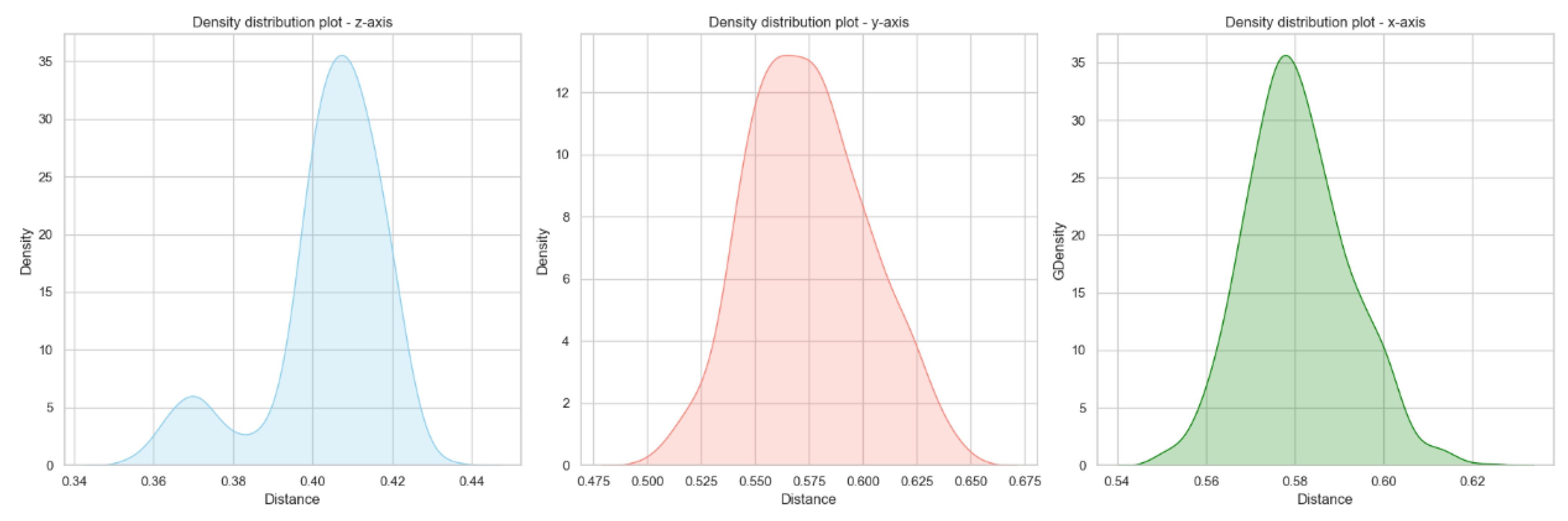
4.1. Phone Multi-Axis Position

The results of the UWB beacon measurement accuracy for two different distances (0.5 m and 2 m) across three different axes (X, Y, and Z) show notable variations in precision and accuracy. For both distances, the Z and X axes show relatively high consistency in measurements, indicated by their low standard deviations (0.01 m). The Y axis, however, shows higher variability (Figure 4 and Figure 5), especially at the 2 m distance, with a standard deviation of 0.06 m and a wider range (1.28 to 2.35 m). At the 0.5 m distance, the mean measurements for the Z (0.40 m), Y (0.57 m), and X axes (0.58 m) indicate that the measurements are reasonably close to the expected value, though there is a slight overestimation in the Y and X axes. At the 2 m distance, the mean measurements for the Z (1.96 m) and X axes (1.88 m) are close to the actual distance, but the Y axis again shows a significant overestimation (2.12 m).
The results indicate that UWB beacon measurements are generally accurate and consistent along the Z and X axes, with minimal deviation from the actual distances. However, measurements along the Y axis exhibit greater variability, particularly at the 2 m distance, highlighting potential issues in the Y axis accuracy for longer distances.

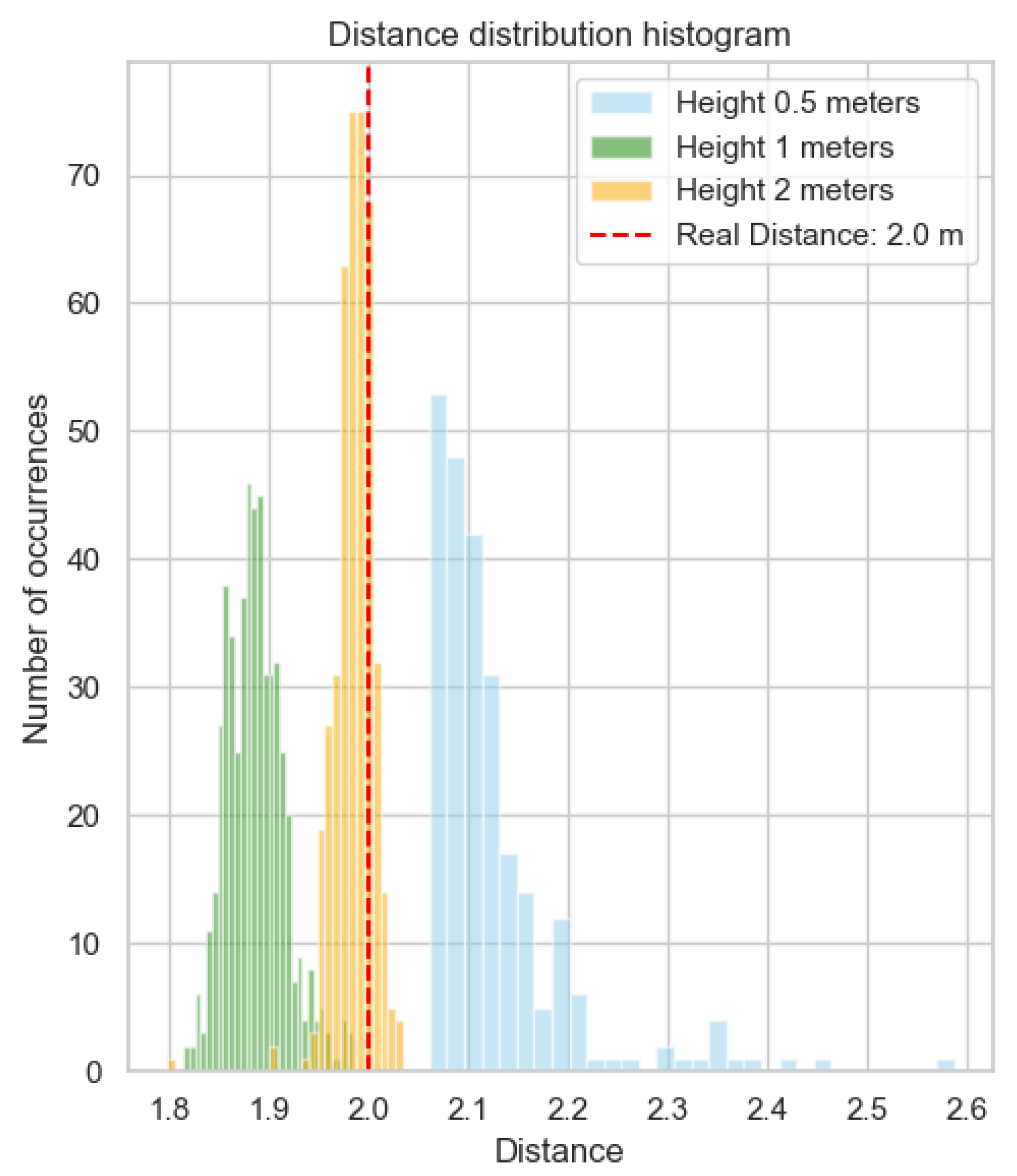
4.2. Different Phone Height

The next stage of the research included measurements and static analyses for various heights (0.5 m, 1 m, and 2 m) using measurement data collected within 300 s at each height (Figure 6). During the measurements, the beacon was placed at a height of 1 m. Each measurement case was adjusted so that the distance between the phone and the beacon was 2 m (Figure 7).

4.3. Various Distance

Distance-related tests were also performed. Measurements were taken at five different distances (0.5 m, 1 m, 1.5 m, 2.0 m, and 2.5 m). The standard deviation (Table 2) is relatively low for all heights, suggesting that the data are relatively clustered around the mean. There was no significant relationship between deviation and increasing distance.

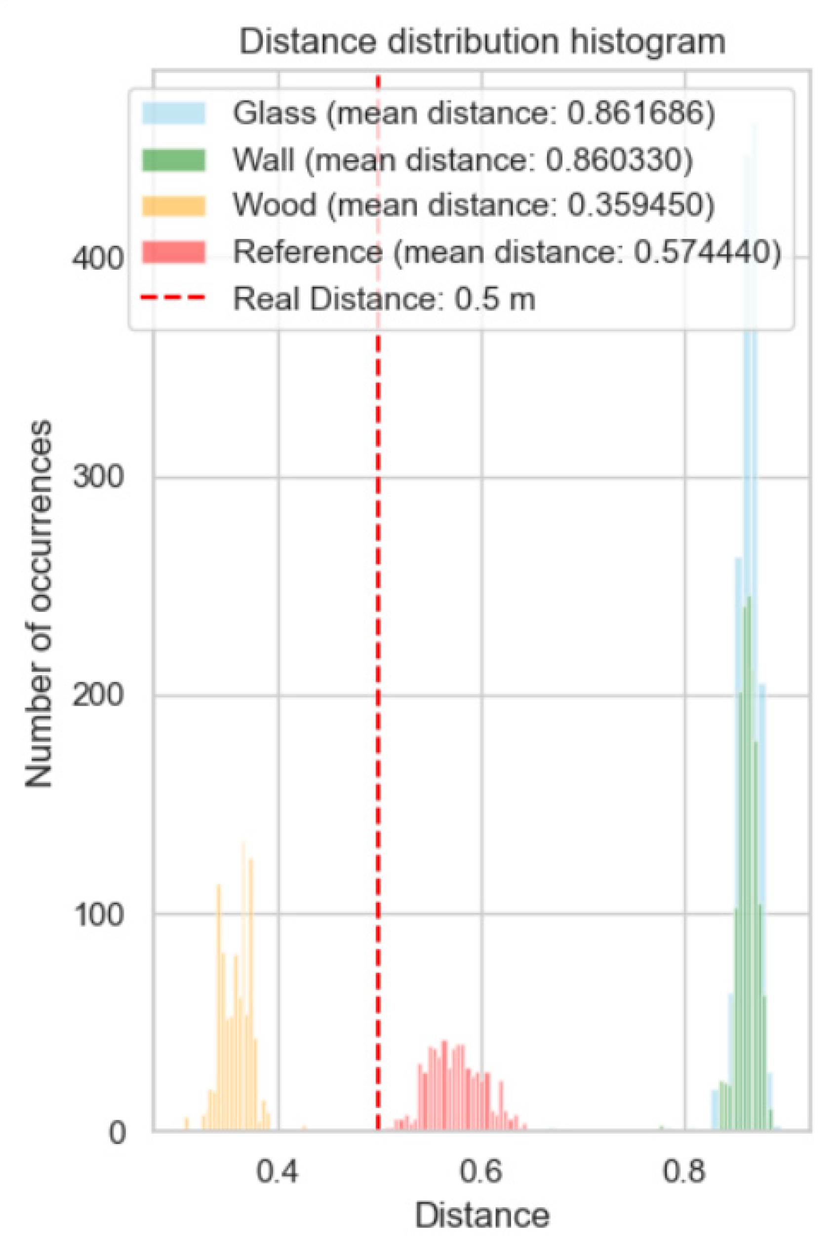
4.4. CameraAssist Option

Table 3 presents statistical summaries of distances measured under different conditions, comparing the use of a CameraAssist tool and measurements without it. The average distance with CameraAssist (0.32) is significantly lower than the distance without CameraAssist (0.58). Similarly, the average distance with CameraAssist (1.80) is lower than without CameraAssist (1.88).
The obstacle test was not possible. With the CameraAssist option enabled, the application always received a measurement once. Moreover, the measurement deviated significantly from the actual value.

4.5. LoS/NLoS Conditions

The standard deviation is larger in NLoS conditions, suggesting greater variability in measurement distances. Under LoS conditions, the average measurement distances are closer to the reference values of 1 m and 2 m; the min and max values are also closer to the values expected in relation to NLoS (Figure 8).
The spread of values is smaller in NLoS conditions, but the distribution of the histogram on the axis deviates from the actual distances. Measurement accuracy below 10 cm was achieved only for 1 m under LoS conditions. Moreover, the number of measurements received in the same time interval (300 s) is almost three times higher (887 for 1 m and 863 for 2 m for NLoS conditions) compared to the LoS conditions.

4.6. Impact of Obstacles

Regarding the analysis of the measurement results for different obstacle materials (glass, concrete, and wood) at different distances (0.5 m and 2 m), several conclusions can be drawn. The average distances measured for glass and concrete are significantly greater than the actual distance, suggesting that waves undergo scattering or reflections when passing through these materials (Figure 9 and Figure 10). The minimum and maximum distances differ from the actual distance, confirming that waves are scattered, reflected, or absorbed to varying degrees by different materials.
Concrete appears to be a more effective barrier than wood, which is consistent with expectations given its higher density. Glass, despite its relatively small thickness, also demonstrates properties similar to those of concrete in absorption.
At both distances of 0.5 and 2 m, there are significant outliers in the case of obstacles such as glass or walls. In both cases, wood shows values closest to the actual measurement (Figure 11).

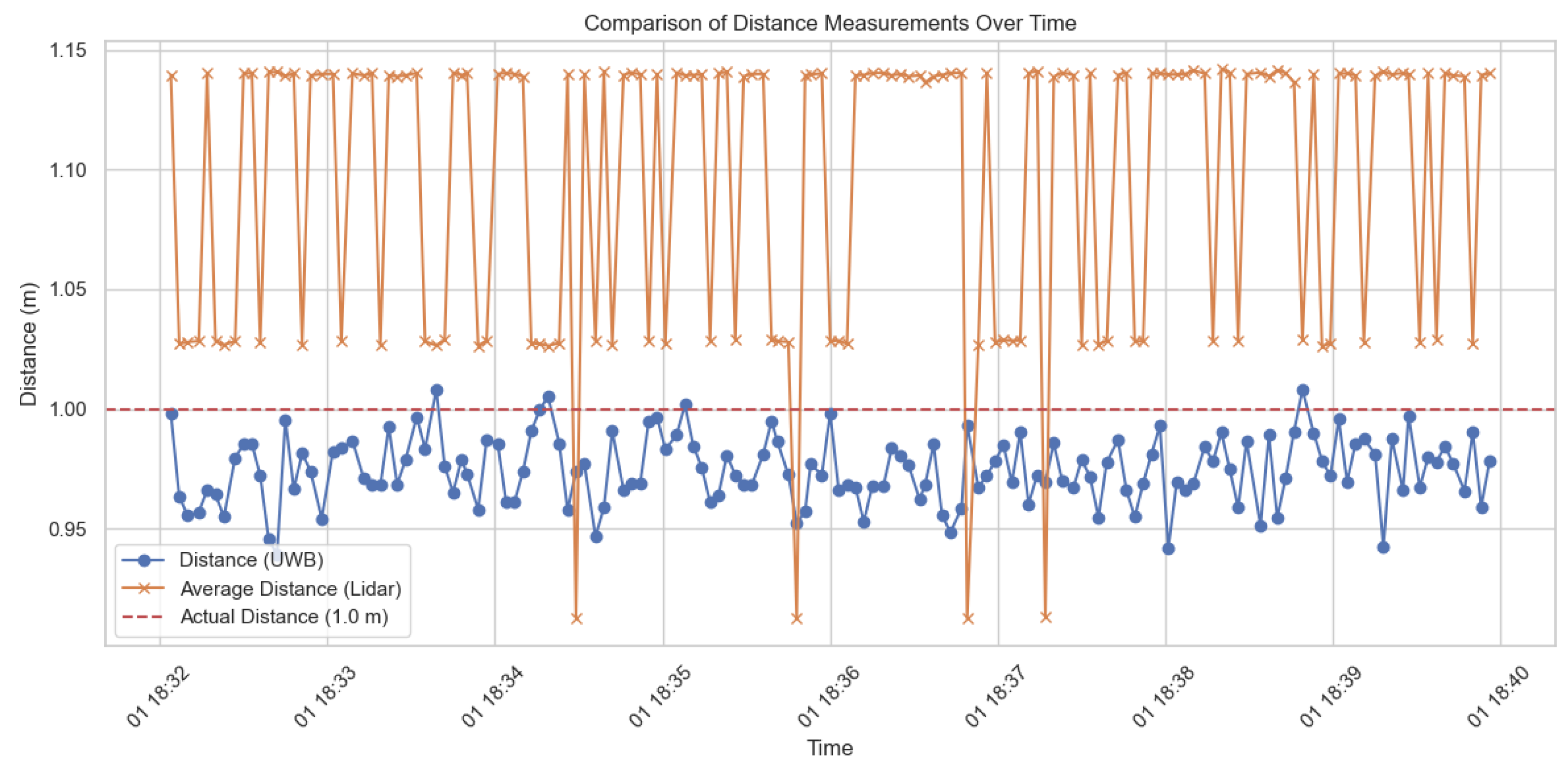
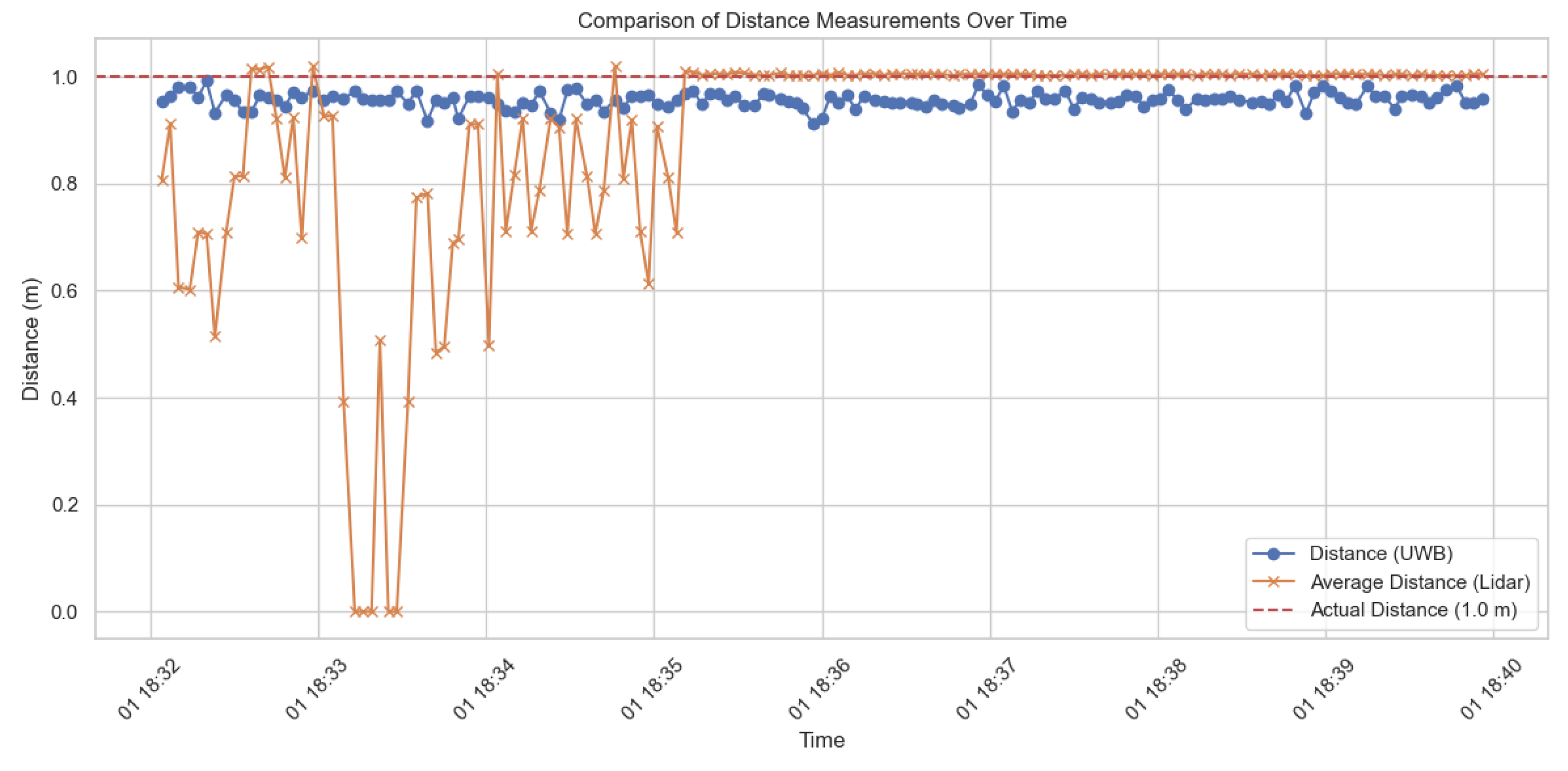
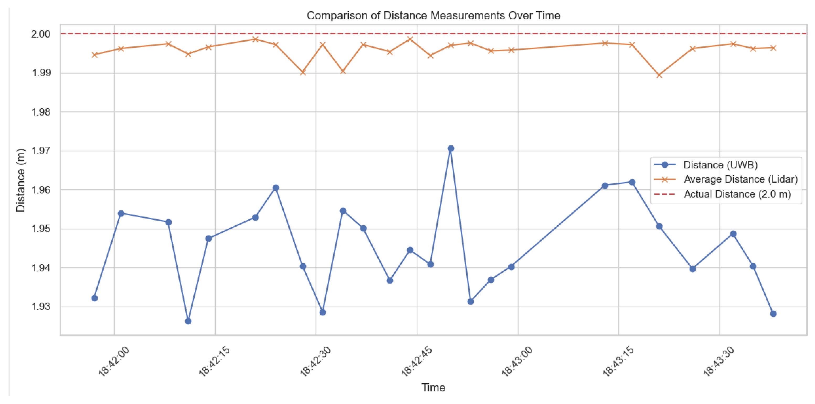
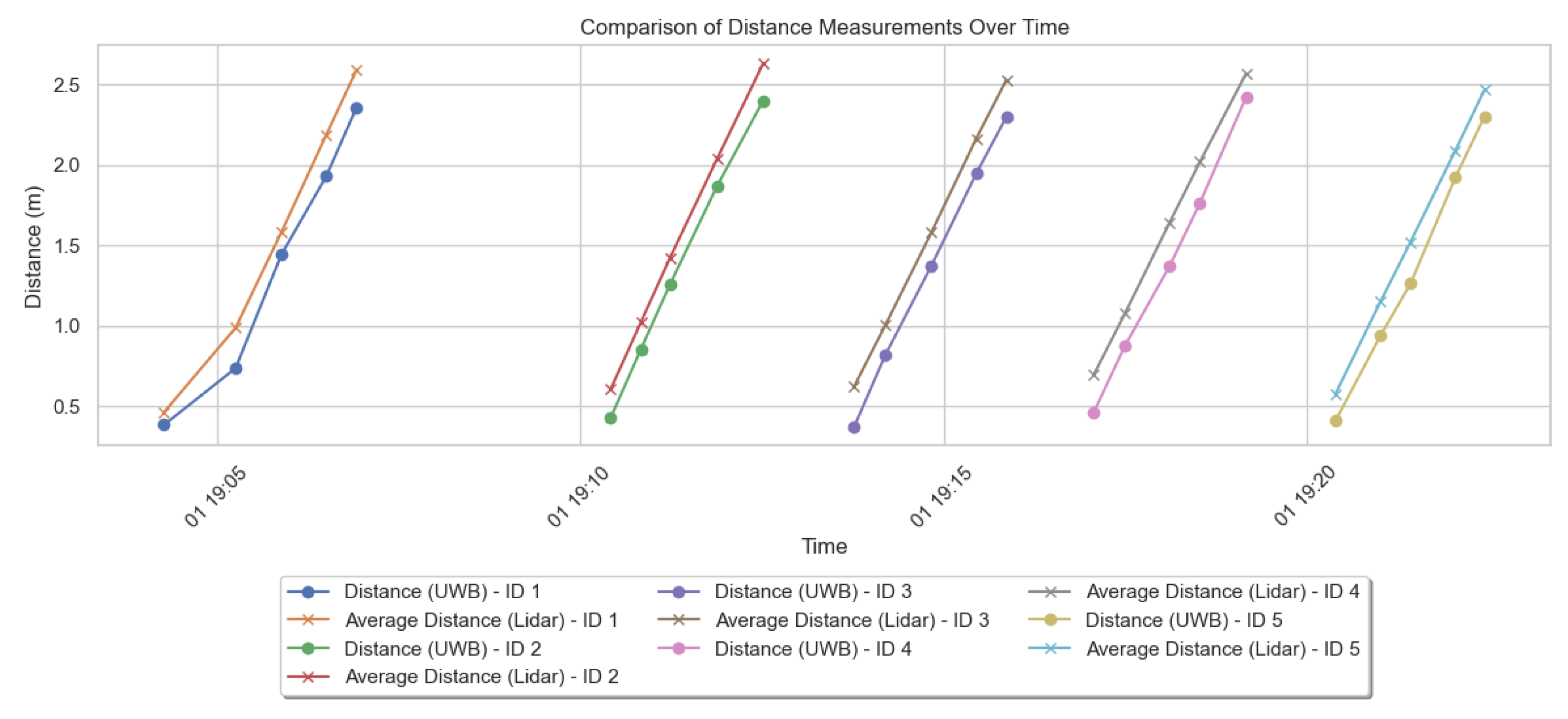
4.7. LIDAR and UWB Comparison

LIDAR and UWB, two positioning systems with similar accuracy designed primarily for indoor environments, were also evaluated. While the static assessment aims to demonstrate the long-term average performance and reveal potential bias, the dynamic part is intended to show performance when applied to a mobile robot and reveal potential short-term error. We assessed the measurement accuracy (static case) and timeliness (dynamic case). The measurements were carried out in a room with dimensions 4 × 5 m, equipped with various objects, thus imitating a realistic home environment. The evaluation consisted of two main parts: static (Figure 12, Figure 13, Figure 14, Figure 15, Figure 16 and Figure 17) and dynamic (Figure 18).
In the dynamic scenario, the mobile robot was equipped with a mobile phone and traversed the trajectory through the room with naturally occurring obstacles (furniture, people, and other devices communicating via radio signals, e.g., UWB, Wi-Fi, Bluetooth). Data were recorded every 0.5 m of the mobile platform’s distance. The robot moved along a pre-established trajectory at an average velocity of 0.5 m/s. The iPhone was mounted on a mobile robot at a height of 13 cm. In the dynamic scenario, the measurement time was less than 1 s. A car equipped with LIDAR changed its position, and measurements were taken from both the beacons and the LIDAR, which simulated real-world conditions. In this case, to average the results, each measurement was performed five times (Figure 18).
The conducted research aimed to assess the accuracy, durability, and integration capabilities of an ultra-wideband (UWB) beacon-based localization system in a varying environment. As part of the experiments, the impact of various factors such as phone position, CameraAssist, line-of-sight conditions (LoS/NLoS), and the presence of obstacles on location accuracy was analyzed. The reference to the UWB measurement method was LIDAR.
The analysis of the impact of the phone’s distance on the accuracy of the measurements revealed a substantial correlation between the distance separating the smartphone and the beacon and the resultant outcomes, which is also visible in those studies that focused on other environmental options. Differences in phone position along the Z, Y, and X axes caused variability in the measurement accuracy. The Y-axis measurements are less reliable compared to those of the other axes. It can be observed that the average distance values varied depending on the phone’s position, which indicates the need to consider this variability when implementing the localization system. Moreover, data suggest that UWB beacon measurements are more accurate and consistent at higher heights (1 m and 2 m) compared to lower heights (0.5 m). The orientation and positioning of the phone’s antenna at lower heights might not be optimal, leading to less accurate distance measurements.
The analysis of the influence of the CameraAssist feature on measurement accuracy showed that enabling this option worsened the localization precision. This is important as in some situations, e.g., in implementations using iPhone 14 or newer, enabling CameraAssist is necessary.
The measurement results in LoS and NLoS conditions showed significant differences in localization accuracy. In LoS conditions, where there is a direct line of sight between the beacon and the receiver, the average measurement distances were closer to the reference values. It is worth noting that the number of measurements in the NLoS condition was significantly higher than in the LoS condition, which may suggest greater difficulties in localization under limited visibility conditions.
The analysis of the impact of various obstacles on the location accuracy showed that the material of the obstacle significantly affected measurement accuracy. Obstacles such as glass or masonry resulted in greater location errors compared to wooden obstacles. The material of the obstacle significantly affected wave propagation, with denser materials such as concrete and glass showing greater effectiveness in absorbing or reflecting waves than wood. This is an important observation that should be taken into account during the implementation of the location system.
A comparison of the results obtained using LIDAR and UWB beacons showed that both technologies achieved similar accuracy in static conditions. However, under dynamic conditions, the accuracy of measurements obtained using LIDAR was higher. This is because LIDAR is less susceptible to motion-related disturbances.
During the experiment, we observed several problems and limitations of potential solutions based on UWB beacon technology for the navigation of visually impaired individuals. First, localization accuracy in NLoS was lower than in LoS conditions, suggesting that the system may have difficulty localizing under limited visibility. Moreover, comparing the results obtained with LIDAR and UWB beacons, we noticed that in dynamic conditions the accuracy of measurements obtained using LIDAR was higher. Despite UWB’s tendency to underestimate the results, this system can still be valuable in dynamic environments. This is due to its stability and relatively low standard deviation compared to LIDAR. In summary, measurements using LIDAR and UWB positioning systems reveal differences in measurement accuracy depending on static and dynamic conditions, as well as variations in susceptibility to disturbances related to movement and environmental obstacles.
Based on the conducted research, it may seem clear that location accuracy depends on various factors, such as phone position, LoS conditions, and the type of obstacle. Additionally, comparing the results obtained using different location technologies, we can notice that every one of these technologies comes with its own set of benefits and drawbacks. Nevertheless, considering all the arguments for and against based on the measurements performed, UWB beacon technology has promising prospects for the future.
To improve localization accuracy in NLoS conditions, data fusion from different sensors can be considered. Numerous studies attempt to achieve results with sub-centimeter accuracy using methods such as fusion or angle of arrival/departure (AoA/AoD) [86]. Moreover, research conducted by [87] demonstrates that with the emergence of new AoA/AoD-based methods, BLE can achieve better accurate measurements than existing RSSI-based methods. In response to market demand, with the release of Bluetooth 5.1, there was a focus on the centimeter-level indoor positioning market. The Bluetooth 5.1 specification, released in December 2020 [88], supports two methods for determining the direction of a Bluetooth signal. Both methods are based on the use of antenna arrays: AoA and AoD.
In the analysis carried out by [89], stationary evaluations of BLE versions 4.2 (older) and 5.0 (newer) were executed. The researchers demonstrated that under line-of-sight (LoS) conditions in a sports hall when using only AoA to estimate the distance to the device, the average error was 0.04 m on the X axis and 0.01 m on the Y axis. Consistent with prior research, it was noted that as the separation between the beacon and the device increased, the error likewise escalated. Additionally, it has been illustrated that this error is amplified by multipath interference under NLoS conditions. Methods for AoA mitigation, such as Kalmar filtering (KF) or inertial measurement unit (IMU) fixation, can be applied to minimize errors. Subsequent research explores the potential of leveraging AoA and AoD data provided by BLE5.1 to ascertain the device’s position. In the empirical study, an error below 0.85 m was achieved for more than 95% of the locations, indicating that sub-meter AoA precision can be attained. Nevertheless, considerable efforts are still required to reach centimeter-level precision.
The integration of these various technologies may allow for greater location accuracy in conditions with limited visibility. Moreover, in the context of the development of UWB technology, more advanced and competitive solutions based on beacons compatible with Apple and Android devices may be available in the future. It is worth noting that currently, there is only a small number of competitive hardware products compatible with UWB beacons on the market, which limits the possibility of result comparison. In the future, the development of UWB technology can lead to an increase in the availability of competitive hardware, enabling a more comprehensive assessment of the accuracy and effectiveness of this technology.

5. Conclusions

This study provides insight into the measurement accuracy of UWB beacons based on TWR technology. The research methodology allowed for a detailed evaluation of the impact of diverse factors on measurement accuracy and the identification of areas for further improvement in this technology. A comparison of the results obtained using LIDAR and UWB beacons allowed for the assessment of the advantages and disadvantages of both technologies and indicated the areas in which each of these technologies can best be used. The methodology for testing the accuracy of UWB beacons based on TWR technology involved a series of experiments aimed at assessing the accuracy of measurements in various static and dynamic conditions. This study allowed us to gain a clearer insight into the effects of various factors on the measurement accuracy of UWB beacons and the identification of potential areas for improvement.
Our research identified areas where the planned location system based on UWB beacons could be enhanced, for instance, when considering the variability of the phone’s position or improving the location accuracy in NLoS conditions. To improve localization accuracy in NLoS conditions, the use of data fusion from different sensors can be considered. A significant insight may be revealed from integrating technologies to further enhance the level of geolocation services. As we live in a physical reality where interaction with spatial orientation-assisting devices occurs, the challenge lies in developing an algorithm that provides an effective collaboration between these technologies. Research aimed at enhancing localization accuracy for indoor navigation systems primarily focuses on integrating additional data from sensors such as accelerometers and magnetometers [90]. Other techniques include real-time filtering, dead reckoning algorithms with step detection, or point multiplication [91]. Emerging approaches in sensor fusion, combining UWB with vision, IMU, or other localization technologies, are also valuable for further research in this field [92]. Another emerging trend is the integration of UWB tracking with machine learning and AI. By harnessing the power of artificial intelligence algorithms, UWB tracking systems can intelligently analyze and interpret vast volumes of data generated by UWB sensors [93]. This enables the development of advanced tracking algorithms capable of adapting to changing environments.
Numerous insights can be derived from the conducted research. First, in dynamic conditions, the accuracy of measurements obtained using LIDAR was higher than those obtained using UWB beacons. Secondly, to improve localization accuracy under NLoS conditions, the use of data fusion from various sensors can be considered. Finally, the development of UWB technology may lead to an increase in the availability of competitive hardware, enabling a more comprehensive assessment of the accuracy and effectiveness of this technology and the implementation of a well-functioning system.

Author Contributions

Conceptualization, M.R. and M.M.; methodology, M.R. and M.K.; software, M.R.; validation, M.M. and M.K.; formal analysis, M.R., M.K. and M.M.; investigation, M.R. and M.K.; resources, M.R. and M.K.; data curation, M.R.; writing—original draft preparation, M.R., M.K. and M.M.; writing—review and editing, M.R., M.K. and M.M.; visualization, M.R. and M.M.; supervision, M.R. and M.M.; project administration, M.M. All authors have read and agreed to the published version of the manuscript.

Funding

This publication was supported by the Excellence Initiative—Research University Program implemented at the Silesian University of Technology in 2024.

Institutional Review Board Statement

Not applicable.

Informed Consent Statement

Not applicable.

Data Availability Statement

Data are contained within the article.

Conflicts of Interest

The authors declare no conflicts of interest.

References

  1. Forrest, S.L.; Mercado, C.L.; Engmann, C.M.; Stacey, A.W.; Hariharan, L.; Khan, S.; Cabrera, M.T. Does the Current Global Health Agenda Lack Vision? Glob. Health Sci. Pract. 2023, 11, e2200091. [Google Scholar] [CrossRef] [PubMed]
  2. Fisher, D.E.; Ward, M.M.; Hoffman, H.J.; Li, C.-M.; Cotch, M.F. Impact of Sensory Impairments on Functional Disability in Adults with Arthritis. Am. J. Prev. Med. 2016, 50, 454–462. [Google Scholar] [CrossRef] [PubMed]
  3. Peter, M.G.; Porada, D.K.; Regenbogen, C.; Olsson, M.J.; Lundström, J.N. Sensory loss enhances multisensory integration performance. Cortex 2019, 120, 116–130. [Google Scholar] [CrossRef]
  4. Lu, C.-L.; Liu, Z.-Y.; Huang, J.-T.; Huang, C.-I.; Wang, B.-H.; Chen, Y.; Wu, N.-H.; Wang, H.-C.; Giarré, L.; Kuo, P.-Y. Assistive Navigation Using Deep Reinforcement Learning Guiding Robot With UWB/Voice Beacons and Semantic Feedbacks for Blind and Visually Impaired People. Front. Robot. AI 2021, 8, 654132. [Google Scholar] [CrossRef] [PubMed]
  5. Dakopoulos, D.; Bourbakis, N.G. Wearable obstacle avoidance electronic travel aids for blind: A survey. IEEE Trans. Syst. Man Cybern. Part C Appl. Rev. 2010, 40, 25–35. [Google Scholar] [CrossRef]
  6. Patel, I.; Kulkarni, M.; Mehendale, N. Review of sensor-driven assistive device technologies for enhancing navigation for the visually impaired. Multimed. Tools Appl. 2023, 83, 52171–52195. [Google Scholar] [CrossRef]
  7. E Kruk, M.; Pate, M. The Lancet Global Health Commission on High Quality Health Systems 1 year on: Progress on a global imperative. Lancet Glob. Health 2020, 8, E30–E32. [Google Scholar] [CrossRef] [PubMed]
  8. The Technology of Electronic Travel Aids—Electronic Travel AIDS: New Directions for Research—NCBI Bookshelf. Available online: https://www.ncbi.nlm.nih.gov/books/NBK218025/ (accessed on 26 June 2024).
  9. Soleimanijavid, A.; Konstantzos, I.; Liu, X. Challenges and opportunities of occupant-centric building controls in real-world implementation: A critical review. Energy Build. 2024, 308, 113958. [Google Scholar] [CrossRef]
  10. Messaoudi, M.D.; Menelas, B.-A.J.; Mcheick, H. Review of Navigation Assistive Tools and Technologies for the Visually Impaired. Sensors 2022, 22, 7888. [Google Scholar] [CrossRef]
  11. Li, C.T.; Cheng, J.C.; Chen, K. Top 10 technologies for indoor positioning on construction sites. Autom. Constr. 2020, 118, 103309. [Google Scholar] [CrossRef]
  12. Su, H.-K.; Liao, Z.-X.; Lin, C.-H.; Lin, T.-M. A hybrid indoor-position mechanism based on bluetooth and WiFi communications for smart mobile devices. In Proceedings of the 2015 International Symposium on Bioelectronics and Bioinformatics (ISBB), Beijing, China, 14–17 October 2015; pp. 188–191. [Google Scholar] [CrossRef]
  13. Syazwani, C.J.N.; Wahab, N.H.A.; Sunar, N.; Ariffin, S.H.S.; Wong, K.Y.; Aun, Y. Indoor Positioning System: A Review. Int. J. Adv. Comput. Sci. Appl. 2022, 13, 477–490. [Google Scholar] [CrossRef]
  14. Elsanhoury, M.; Siemuri, A.; Nieminen, J.; Välisuo, P.; Koljonen, J.; Kuusniemi, H.; Elmusrati, M.S. Emerging Wireless Technologies for Reliable Indoor Navigation in Industrial Environments. In Proceedings of the 36th International Technical Meeting of the Satellite Division of the Institute of Navigation (ION GNSS+ 2023), Denver, CO, USA, 11–15 September 2023; pp. 1706–1714. [Google Scholar] [CrossRef]
  15. FiRA Annual Report 2022. Available online: https://www.firaconsortium.org/sites/default/files/2023-02/fira-annual-report-2022.pdf (accessed on 19 May 2024).
  16. Smartphone High Accuracy Real-Time Location to Drive UWB-Enabled Devices to 1.3 Billion Shipments by 2026. Available online: https://www.abiresearch.com/press/smartphone-high-accuracy-real-time-location-drive-uwb-enabled-devices-13-billion-shipments-2026/ (accessed on 19 May 2024).
  17. Unleashing the Potential of UWB: Regulatory Considerations. Available online: https://www.allaboutcircuits.com/uploads/articles/UWBWP.pdf (accessed on 18 May 2024).
  18. Annual Report 2021. Available online: https://www.firaconsortium.org/sites/default/files/2022-02/FiRa-Annual-Report-2021.pdf (accessed on 18 May 2024).
  19. Ultra-Wideband UWB: Omlox. Available online: https://omlox.com/omlox-explained/ultra-wideband-uwb (accessed on 18 May 2024).
  20. Alhadhrami, S.; Alnafessah, A.; Al-Ammar, M.; Alarifi, A.; Al-Khalifa, H.; Alsaleh, M. UWB Indoor Tracking System for Visually Impaired People. In Proceedings of the MoMM 2015: The 13th International Conference on Advances in Mobile Computing and Multimedia, MoMM 2015—Proceedings, Brussels, Belgium, 11–13 December 2015. [Google Scholar] [CrossRef]
  21. Rivai, M.; Hutabarat, D.; Nafis, Z.M.J. 2D mapping using omni-directional mobile robot equipped with LiDAR. Telkomnika Telecommun. Comput. Electron. Control. 2020, 18, 1467–1474. [Google Scholar] [CrossRef]
  22. Deak, G.; Curran, K.; Condell, J. A survey of active and passive indoor localisation systems. Comput. Commun. 2012, 35, 1939–1954. [Google Scholar] [CrossRef]
  23. Hayward, S.; van Lopik, K.; Hinde, C.; West, A. A Survey of Indoor Location Technologies, Techniques and Applications in Industry. Internet Things 2022, 20, 100608. [Google Scholar] [CrossRef]
  24. Liu, Q.; Yin, Z.; Zhao, Y.; Wu, Z.; Wu, M. UWB LOS/NLOS identification in multiple indoor environments using deep learning methods. Phys. Commun. 2022, 52, 101695. [Google Scholar] [CrossRef]
  25. Arai, T.; Yoshizawa, T.; Aoki, T.; Zempo, K.; Okada, Y. Evaluation of Indoor Positioning System based on Attachable Infrared Beacons in Metal Shelf Environment. In Proceedings of the 2019 IEEE International Conference on Consumer Electronics (ICCE), Las Vegas, NV, USA, 11–13 January 2019. [Google Scholar] [CrossRef]
  26. Xiao, Z.; Wen, H.; Markham, A.; Trigoni, N.; Blunsom, P.; Frolik, J. Non-Line-of-Sight Identification and Mitigation Using Received Signal Strength. IEEE Trans. Wirel. Commun. 2015, 14, 1689–1702. [Google Scholar] [CrossRef]
  27. Vaz, R.; Freitas, D.; Coelho, A. Blind and visually impaired visitors’ experiences in museums: Increasing accessibility through assistive technologies. Int. J. Incl. Mus. 2020, 13, 57–80. [Google Scholar] [CrossRef]
  28. Nakajima, M.; Haruyama, S. New indoor navigation system for visually impaired people using visible light communication. EURASIP J. Wirel. Commun. Netw. 2013, 2013, 37. [Google Scholar] [CrossRef]
  29. Xue, L.; Zhang, Z.; Xu, L.; Gao, F.; Zhao, X.; Xun, X.; Zhao, B.; Kang, Z.; Liao, Q.; Zhang, Y. Information accessibility oriented self-powered and ripple-inspired fingertip interactors with auditory feedback. Nano Energy 2021, 87, 106117. [Google Scholar] [CrossRef]
  30. Faisal, F.; Hasan, M.; Sabrin, S.; Hasan, Z.; Siddique, A.H. Voice Activated Portable Braille with Audio Feedback. In Proceedings of the 2021 2nd International Conference on Robotics, Electrical and Signal Processing Techniques (ICREST), Dhaka, Bangladesh, 5–7 January 2021. [Google Scholar] [CrossRef]
  31. Choi, J.; Gill, H.; Ou, S.; Lee, J. CCVoice: Voice to Text Conversion and Management Program Implementation of Google Cloud Speech API. KIISE Trans. Comput. Pract. 2019, 25, 191–197. [Google Scholar] [CrossRef]
  32. Gabler, D. András Márton: Les pratiques funéraires en Pannonie de l’époque augustéenne à la fin du 3e siècle. Acta Archaeol. Acad. Sci. Hung. 2021, 72, 241–245. [Google Scholar] [CrossRef]
  33. Santhosh, S.S.; Sasiprabha, T.; Jeberson, R. BLI—NAV embedded navigation system for blind people. In Proceedings of the 2010 Recent Advances in Space Technology Services and Climate Change (RSTSCC), Chennai, India, 13–15 November 2010. [Google Scholar] [CrossRef]
  34. Dian, Z.; Kezhong, L.; Rui, M. A precise RFID indoor localization system with sensor network assistance. China Commun. 2015, 12, 13–22. [Google Scholar] [CrossRef]
  35. Park, S.; Choi, I.-M.; Kim, S.-S.; Kim, S.-M. A portable mid-range localization system using infrared LEDs for visually impaired people. Infrared Phys. Technol. 2014, 67, 583–589. [Google Scholar] [CrossRef]
  36. Chen, H.; Wang, K.; Yang, K. Improving realsense by fusing color stereo vision and infrared stereo vision for the visually impaired. In Proceedings of the 2018 International Conference on Information Science and System, Jeju, Republic of Korea, 27 April 2018. [Google Scholar] [CrossRef]
  37. Rehrl, K.; Leitinger, S.; Bruntsch, S.; Mentz, H. Assisting orientation and guidance for multimodal travelers in situations of modal change. In Proceedings of the 2005 IEEE Intelligent Transportation Systems, Vienna, Austria, 16 September 2005. [Google Scholar] [CrossRef]
  38. Mahalle, S. Ultrasonic Spectacles & Waist- Belt for Visually Impaired & Blind Person. IOSR J. Eng. 2014, 4, 46–49. [Google Scholar] [CrossRef]
  39. dos Santos, A.D.P.; Medola, F.O.; Cinelli, M.J.; Ramirez, A.R.G.; Sandnes, F.E. Are electronic white canes better than traditional canes? A comparative study with blind and blindfolded participants. Univers. Access Inf. Soc. 2021, 20, 93–103. [Google Scholar] [CrossRef]
  40. Higuchi, H.; Harada, A.; Iwahashi, T.; Usui, S.; Sawamoto, J.; Kanda, J.; Wakimoto, K.; Tanaka, S. Network-based nationwide RTK-GPS and indoor navigation intended for seamless location based services. In Proceedings of the National Technical Meeting, Institute of Navigation, San Diego, CA, USA, 26–28 January 2004. [Google Scholar]
  41. Caffery, J.; Stuber, G. Overview of radiolocation in CDMA cellular systems. IEEE Commun. Mag. 1998, 36, 38–45. [Google Scholar] [CrossRef]
  42. Guerrero, L.A.; Vasquez, F.; Ochoa, S.F. An indoor navigation system for the visually impaired. Sensors 2012, 12, 8236–8258. [Google Scholar] [CrossRef] [PubMed]
  43. Satani, N.; Patel, S.; Patel, S. AI Powered Glasses for Visually Impaired Person. Int. J. Recent Technol. Eng. 2020, 9, 316–321. [Google Scholar] [CrossRef]
  44. Chen, H.-E.; Lin, Y.-Y.; Chen, C.-H.; Wang, I.-F. BlindNavi: A Navigation App for the Visually Impaired Smartphone User. In Proceedings of the 33rd Annual ACM Conference Extended Abstracts on Human Factors in Computing Systems, Seoul, Republic of Korea, 18–23 April 2015; Volume 18, pp. 19–24. [Google Scholar] [CrossRef]
  45. Huang, S.; Ishikawa, M.; Yamakawa, Y. An Active assistant robotic system based on high-speed vision and haptic feedback for human-robot collaboration. In Proceedings of the IECON 2018—44th Annual Conference of the IEEE Industrial Electronics Society, Washington, DC, USA, 21–23 October 2018. [Google Scholar] [CrossRef]
  46. Mon, C.S.; Yap, K.M.; Ahmad, A. A preliminary study on requirements of olfactory, haptic and audio enabled application for visually impaired in edutainment. In Proceedings of the 2019 IEEE 9th Symposium on Computer Applications & Industrial Electronics (ISCAIE), Kota Kinabalu, Malaysia, 27–28 April 2019. [Google Scholar] [CrossRef]
  47. Rehrl, K.; Göll, N.; Leitinger, S.; Bruntsch, S.; Mentz, H.-J. Smartphone-based information and navigation aids for public transport travellers. In Location Based Services and TeleCartography; Springer: Berlin/Heidelberg, Germany, 2007. [Google Scholar] [CrossRef]
  48. Zhou, J.; Yeung, W.M.-C.; Ng, J.K.-Y. Enhancing indoor positioning accuracy by utilizing signals from both the mobile phone network and the wireless local area network. In Proceedings of the 22nd International Conference on Advanced Information Networking and Applications (Aina 2008), Okinawa, Japan, 25–28 March 2008. [Google Scholar] [CrossRef]
  49. Karkar, A.; Al-Maadeed, S. Mobile Assistive Technologies for Visual Impaired Users: A Survey. In Proceedings of the 2018 International Conference on Computer and Applications (ICCA), Beirut, Lebanon, 25–26 August 2018. [Google Scholar] [CrossRef]
  50. Menelas, B.; Picinalli, L.; Katz, B.F.G.; Bourdot, P. Audio haptic feedbacks for an acquisition task in a multi-target context. In Proceedings of the 2010 IEEE Symposium on 3D User Interfaces (3DUI 2010), Waltham, MA, USA, 20–21 March 2010. [Google Scholar] [CrossRef]
  51. Liu, Z.; Li, C.; Wu, D.; Dai, W.; Geng, S.; Ding, Q. A wireless sensor network based personnel positioning scheme in coal mines with blind areas. Sensors 2010, 10, 9891–9918. [Google Scholar] [CrossRef]
  52. Hairuman, I.F.B.; Foong, O.-M. OCR signage recognition with skew & slant correction for visually impaired people. In Proceedings of the 2011 11th International Conference on Hybrid Intelligent Systems (HIS 2011), Melacca, Malaysia, 5–8 December 2011; pp. 306–310. [Google Scholar] [CrossRef]
  53. Messaoudi, M.D.; Menelas, B.-A.J.; Mcheick, H. Autonomous Smart White Cane Navigation System for Indoor Usage. Technologies 2020, 8, 37. [Google Scholar] [CrossRef]
  54. A Cellphone Based Indoor wayfindingsystem for the Visually Challenged. Available online: https://assistech.iitd.ac.in/doc/Roshni_Pamphlet.pdf (accessed on 19 May 2024).
  55. Chen, Q.; Khan, M.; Tsangouri, C.; Yang, C.; Li, B.; Xiao, J.; Zhu, Z. CCNY Smart Cane. In Proceedings of the 2017 IEEE 7th Annual International Conference on CYBER Technology in Automation, Control, and Intelligent Systems (CYBER), Honolulu, HI, USA, 31 July–4 August 2017; pp. 1246–1251. [Google Scholar] [CrossRef]
  56. Aladren, A.; Lopez-Nicolas, G.; Puig, L.; Guerrero, J.J. Navigation Assistance for the Visually Impaired Using RGB-D Sensor with Range Expansion. IEEE Syst. J. 2016, 10, 922–932. [Google Scholar] [CrossRef]
  57. Teng, C.-F.; Chen, Y.-L. Syndrome-Enabled Unsupervised Learning for Neural Network-Based Polar Decoder and Jointly Optimized Blind Equalizer. IEEE J. Emerg. Sel. Top. Circuits Syst. 2020, 10, 177–188. [Google Scholar] [CrossRef]
  58. Bai, J.; Liu, D.; Su, G.; Fu, Z. A cloud and vision-based navigation system used for blind people. In Proceedings of the AIACT ‘17: 2017 International Conference on Artificial Intelligence, Automation and Control Technologies, Wuhan, China, 7–9 April 2017; p. 22. [Google Scholar] [CrossRef]
  59. Oladayo, O.O. A Multidimensional Walking Aid for Visually Impaired Using Ultrasonic Sensors Network with Voice Guidance. Int. J. Intell. Syst. Appl. 2014, 6, 53–59. [Google Scholar] [CrossRef]
  60. Sahoo, N.; Lin, H.-W.; Chang, Y.-H. Design and implementation of a walking stick aid for visually challenged people. Sensors 2019, 19, 130. [Google Scholar] [CrossRef]
  61. Kuc, R. Binaural sonar electronic travel aid provides vibrotactile cues for landmark, reflector motion and surface texture classification. IEEE Trans. Biomed. Eng. 2002, 49, 1173–1180. [Google Scholar] [CrossRef]
  62. Nivishna, S.; Vivek, C. Smart indoor and outdoor guiding system for blind people using android and IOT. Indian J. Public Health Res. Dev. 2019, 10, 1108. [Google Scholar] [CrossRef]
  63. Mahmud, N.; Saha, R.; Zafar, R.; Bhuian, M.; Sarwar, S. Vibration and voice operated navigation system for visually impaired person. In Proceedings of the 2014 International Conference on Informatics, Electronics & Vision (ICIEV), Dhaka, Bangladesh, 23–24 May 2014. [Google Scholar] [CrossRef]
  64. Grubb, P.W.; Thomsen, P.R.; Hoxie, T.; Wright, G. Patents for Chemicals, Pharmaceuticals, and Biotechnology; Oxford University Press (OUP): Oxford, UK, 2016. [Google Scholar] [CrossRef]
  65. Kwiecień, A.; Maćkowski, M.; Kojder, M.; Manczyk, M. Reliability of Bluetooth Smart Technology for Indoor Localization System. Commun. Comput. Inf. Sci. 2015, 522, 444–454. [Google Scholar] [CrossRef]
  66. Cominelli, M.; Patras, P.; Gringoli, F. Dead on Arrival: An empirical study of the Bluetooth 5.1 positioning system. In Proceedings of the MobiCom ‘19: The 25th Annual International Conference on Mobile Computing and Networking, Los Cabos, Mexico, 25 October 2019. [Google Scholar] [CrossRef]
  67. Qian, M.; Zhao, K.; Seneviratne, A.; Li, B. Performance analysis of ble 5.1 new feature angle of arrival for relative positioning. ISPRS Int. Arch. Photogramm. Remote Sens. Spat. Inf. Sci. 2022, 46, 155–161. [Google Scholar] [CrossRef]
  68. Leitch, S.G.; Ahmed, Q.Z.; Bin Abbas, W.; Hafeez, M.; Laziridis, P.I.; Sureephong, P.; Alade, T. On Indoor Localization Using WiFi, BLE, UWB, and IMU Technologies. Sensors 2023, 23, 8598. [Google Scholar] [CrossRef]
  69. Bandukda, M.; Singh, A.; Berthouze, N.; Holloway, C. Understanding Experiences of blind individuals in outdoor nature. In Proceedings of the Conference on Human Factors in Computing Systems—Proceedings, Glasgow, UK, 4–9 May 2019; p. LBW1711. [Google Scholar] [CrossRef]
  70. Chen, Z.; Xu, A.; Sui, X.; Wang, C.; Wang, S.; Gao, J.; Shi, Z. Improved-UWB/LiDAR-SLAM Tightly Coupled Positioning System with NLOS Identification Using a LiDAR Point Cloud in GNSS-Denied Environments. Remote Sens. 2022, 14, 1380. [Google Scholar] [CrossRef]
  71. Martins, P.; Abbasi, M.; Sa, F.; Celiclio, J.; Morgado, F.; Caldeira, F. Intelligent beacon location and fingerprinting. Procedia Comput. Sci. 2019, 151, 9–16. [Google Scholar] [CrossRef]
  72. Better Together: How Combining UWB and Bluetooth Low Energy Enables Innovation|NXP Semiconductors. Available online: https://www.nxp.com/company/blog/better-together-how-combining-uwb-and-bluetooth-low-energy-enables-innovation:BL-UWB-AND-BLUETOOTH-LOW-ENERGY (accessed on 18 May 2024).
  73. Farooq-i-Azam, M.; Ayyaz, M.N. Location and Position Estimation in Wireless Sensor Networks; ResearchGate: Berlin, Germany, 2016; pp. 179–214. [Google Scholar] [CrossRef]
  74. Che, F.; Ahmed, Q.Z.; Lazaridis, P.I.; Sureephong, P.; Alade, T. Indoor Positioning System (IPS) Using Ultra-Wide Bandwidth (UWB)—For Industrial Internet of Things (IIoT). Sensors 2023, 23, 5710. [Google Scholar] [CrossRef]
  75. Kim, H. Double-sided two-way ranging algorithm to reduce ranging time. IEEE Commun. Lett. 2009, 13, 486–488. [Google Scholar] [CrossRef]
  76. Ferrari, P.; Flammini, A.; Sisinni, E.; Depari, A.; Rizzi, M.; Exel, R.; Sauter, T. Timestamping and Ranging Performance for IEEE 802.15.4 CSS Systems. IEEE Trans. Instrum. Meas. 2014, 63, 1244–1252. [Google Scholar] [CrossRef]
  77. Fakhoury, S.; Ismail, K. Ultra-Wideband-Based Time Occupancy Analysis for Safety Studies. Sensors 2023, 23, 7551. [Google Scholar] [CrossRef]
  78. Nearby Interaction|Apple Developer Documentation. Available online: https://developer.apple.com/documentation/nearbyinteraction (accessed on 18 May 2024).
  79. GitHub—Estimote/iOS-Estimote-UWB-SDK: iOS SDK and Demo App for Estimote UWB Beacons. Available online: https://github.com/Estimote/iOS-Estimote-UWB-SDK (accessed on 19 May 2024).
  80. isCameraAssistanceEnabled|Apple Developer Documentation. Available online: https://developer.apple.com/documentation/nearbyinteraction/ninearbypeerconfiguration/4013050-iscameraassistanceenabled (accessed on 18 May 2024).
  81. Delamare, M.; Boutteau, R.; Savatier, X.; Iriart, N. Static and Dynamic Evaluation of an UWB Localization System for Industrial Applications. Sci 2020, 2, 23. [Google Scholar] [CrossRef]
  82. Smartphones with UWB: Evaluating the Accuracy and Reliability of UWB Ranging|Request PDF. Available online: https://www.researchgate.net/publication/369379894_Smartphones_with_UWB_Evaluating_the_Accuracy_and_Reliability_of_UWB_Ranging (accessed on 18 May 2024).
  83. (PDF) High-Accuracy Ranging and Localization with Ultra-Wideband Communications for Energy-Constrained Devices. Available online: https://www.researchgate.net/publication/351062898_High-Accuracy_Ranging_and_Localization_with_Ultra-Wideband_Communications_for_Energy-Constrained_Devices (accessed on 18 May 2024).
  84. Flueratoru, L.; Wehrli, S.; Magno, M.; Niculescu, D. On the Energy Consumption and Ranging Accuracy of Ultra-Wideband Physical Interfaces. In Proceedings of the GLOBECOM 2020—2020 IEEE Global Communications Conference, Taipei, China, 7–11 December 2020; pp. 1–7. [Google Scholar] [CrossRef]
  85. Wang, F.; Tang, H.; Chen, J. Survey on NLOS Identification and Error Mitigation for UWB Indoor Positioning. Electronics 2023, 12, 1678. [Google Scholar] [CrossRef]
  86. Decarli, N.O.; Wilab, D.D.; Gezici, S.; Alberto, A.; Amico, D. LOS/NLOS Detection for UWB Signals: A Comparative Study Using Experimental Data. In Proceedings of the IEEE 5th International Symposium on Wireless Pervasive Computing 2010, Modena, Italy, 5–7 May 2010. [Google Scholar]
  87. Crețu-Sîrcu, A.L.; Schiøler, H.; Cederholm, J.P.; Sîrcu, I.; Schjørring, A.; Larrad, I.R.; Berardinelli, G.; Madsen, O. Evaluation and Comparison of Ultrasonic and UWB Technology for Indoor Localization in an Industrial Environment. Sensors 2022, 22, 2927. [Google Scholar] [CrossRef]
  88. Wan, Q.; Wu, T.; Zhang, K.; Liu, X.; Cheng, K.; Liu, J.; Zhu, J. A high precision indoor positioning system of BLE AOA based on ISSS algorithm. Measurement 2024, 224, 113801. [Google Scholar] [CrossRef]
  89. Woolley, M. Bluetooth Core Specification v5.1 Feature Overview; Bluetooth Core Specification v5.1 Contains a Series of Updates to the Bluetooth® Core Specification. This Document Summarizes and Explains Each Change. Bluetooth Core Specification v5.1 Should be Consulted for Full Details; Bluetooth SIG: Kirkland, WA, USA, 2019. [Google Scholar]
  90. Ramirez, R.; Huang, C.-Y.; Liao, C.-A.; Lin, P.-T.; Lin, H.-W.; Liang, S.-H. A Practice of BLE RSSI Measurement for Indoor Positioning. Sensors 2021, 21, 5181. [Google Scholar] [CrossRef] [PubMed]
  91. You, W.; Li, F.; Liao, L.; Huang, M. Data Fusion of UWB and IMU Based on Unscented Kalman Filter for Indoor Localization of Quadrotor UAV. IEEE Access 2020, 8, 64971–64981. [Google Scholar] [CrossRef]
  92. Woo, H.-J.; Seo, D.-M.; Kim, M.-S.; Park, M.-S.; Hong, W.-H.; Baek, S.-C. Localization of Cracks in Concrete Structures Using an Unmanned Aerial Vehicle. Sensors 2022, 22, 6711. [Google Scholar] [CrossRef]
  93. UWB and AI overview—By Giorgio Zanella—Technotrend. Available online: https://technotrend.substack.com/p/uwb-and-ai-overview (accessed on 18 June 2024).
Figure 1. Diagram of the measurement system.
Applsci 14 05646 g001
Figure 2. Visualization of the measurement room using the SLAM algorithm.
Applsci 14 05646 g002
Figure 3. UWB measurement graph for voltage 3.0.
Applsci 14 05646 g003
Figure 4. Density distribution plot for multi-axis phone position for 0.5 m.
Applsci 14 05646 g004
Figure 5. Density distribution plot for multi-axis phone position for 2 m.
Applsci 14 05646 g005
Figure 6. Box plots for multi-axis phone positions for different heights.
Applsci 14 05646 g006
Figure 7. Distance distribution histogram for different phone heights.
Applsci 14 05646 g007
Figure 8. Distance distribution histogram for LoS and NLoS measurements.
Applsci 14 05646 g008
Figure 9. Box plots of obstacles made of different materials for measurement at a distance of 0.5 m.
Applsci 14 05646 g009
Figure 10. Box plots of obstacles made of different materials for measurement at a distance of 2 m.
Applsci 14 05646 g010
Figure 11. Distance distribution histogram for obstacles.
Applsci 14 05646 g011
Figure 12. Comparison of distance measurements over time; actual distance: 0.5 m; front beacon.
Applsci 14 05646 g012
Figure 13. Comparison of distance measurements over time; actual distance: 0.5 m; back beacon.
Applsci 14 05646 g013
Figure 14. Comparison of distance measurements over time; actual distance: 1.0 m; front beacon.
Applsci 14 05646 g014
Figure 15. Comparison of distance measurements over time; actual distance: 1.0 m; back beacon.
Applsci 14 05646 g015
Figure 16. Comparison of distance measurements over time; actual distance: 2.0 m; front beacon.
Applsci 14 05646 g016
Figure 17. Comparison of distance measurements over time; actual distance: 2.0 m; back beacon.
Applsci 14 05646 g017
Figure 18. Comparison of distance measurements for dynamic conditions.
Applsci 14 05646 g018
Table 1. Distance measurement methods.
Time-based:ToATDoATW-ToAPoA
Signal-based:RSSICSI
Angulation:AoAAoD
Proximity Detection:RFIDCell-ID
Table 2. Distance measurements—multi-axis test position for 2 m.
Distance
0.5 [m]
Distance
1 [m]
Distance
1.5 [m]
Distance
2 [m]
Distance
2.5 [m]
count93760210241039993
mean0.581.101.421.882.39
std0.010.010.020.010.02
min0.551.050.991.842.32
max0.621.131.461.922.44
Table 3. Distance measurements using the CameraAssist option.
Distance with CameraAssist
(0.5 [m])
Distance without CameraAssist
(0.5 [m])
Distance with Camera Assist
(2 [m])
Distance without CameraAssist
(2 [m])
mean0.320.581.801.88
std0.010.010.010.01
min0.290.551.791.84
max0.360.621.811.92
Disclaimer/Publisher’s Note: The statements, opinions and data contained in all publications are solely those of the individual author(s) and contributor(s) and not of MDPI and/or the editor(s). MDPI and/or the editor(s) disclaim responsibility for any injury to people or property resulting from any ideas, methods, instructions or products referred to in the content.

