
Parametric Study on the Buckling of Unbraced Steel Frames under Fire Situation

Abstract
:1. Introduction
2. Materials and Methods
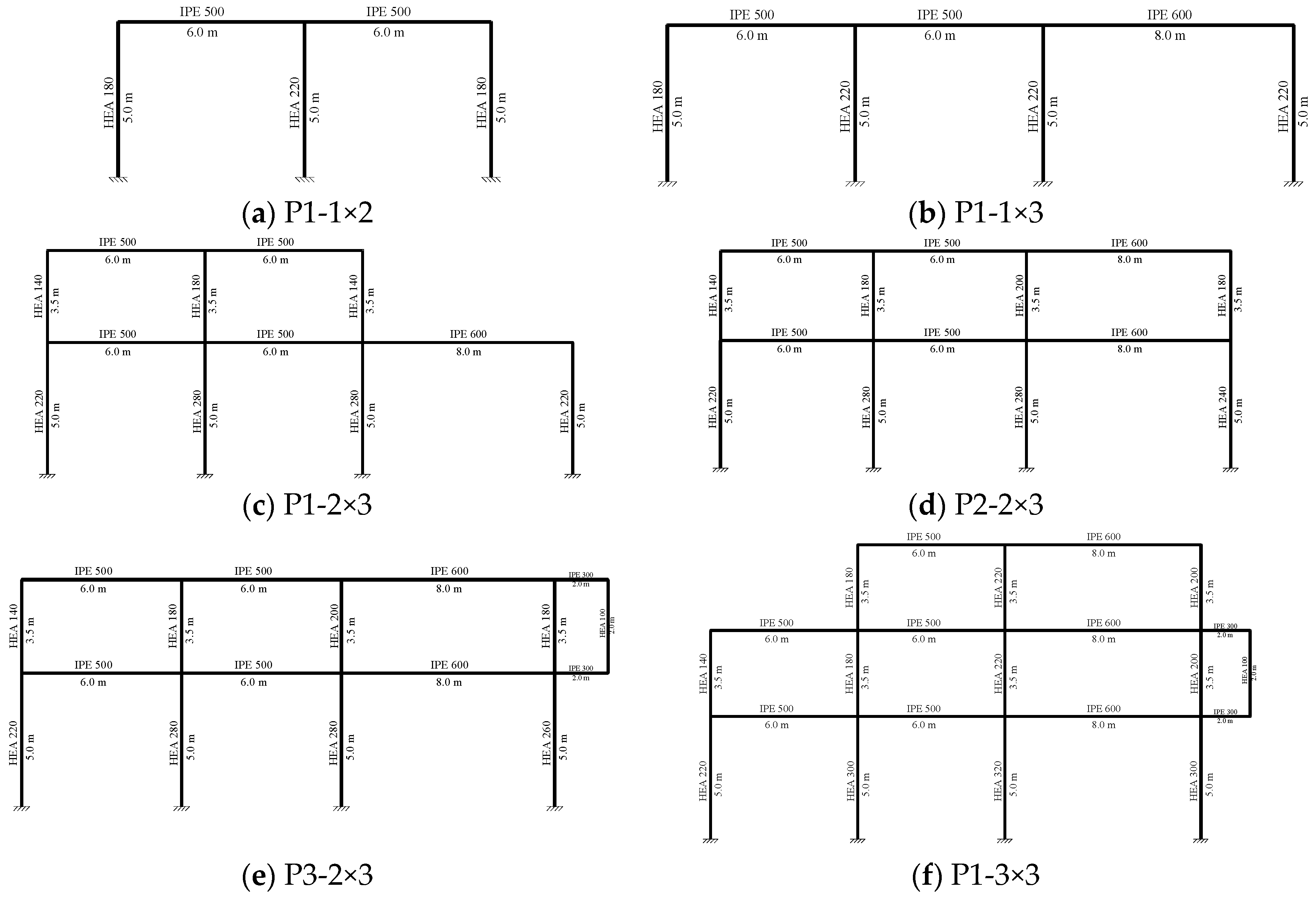
2.1. Methodology Used in the Design of the Structure
2.2. Methodology Used to Determine the Critical Column of the Frame at Normal Temperature (20 °C) and in Fire
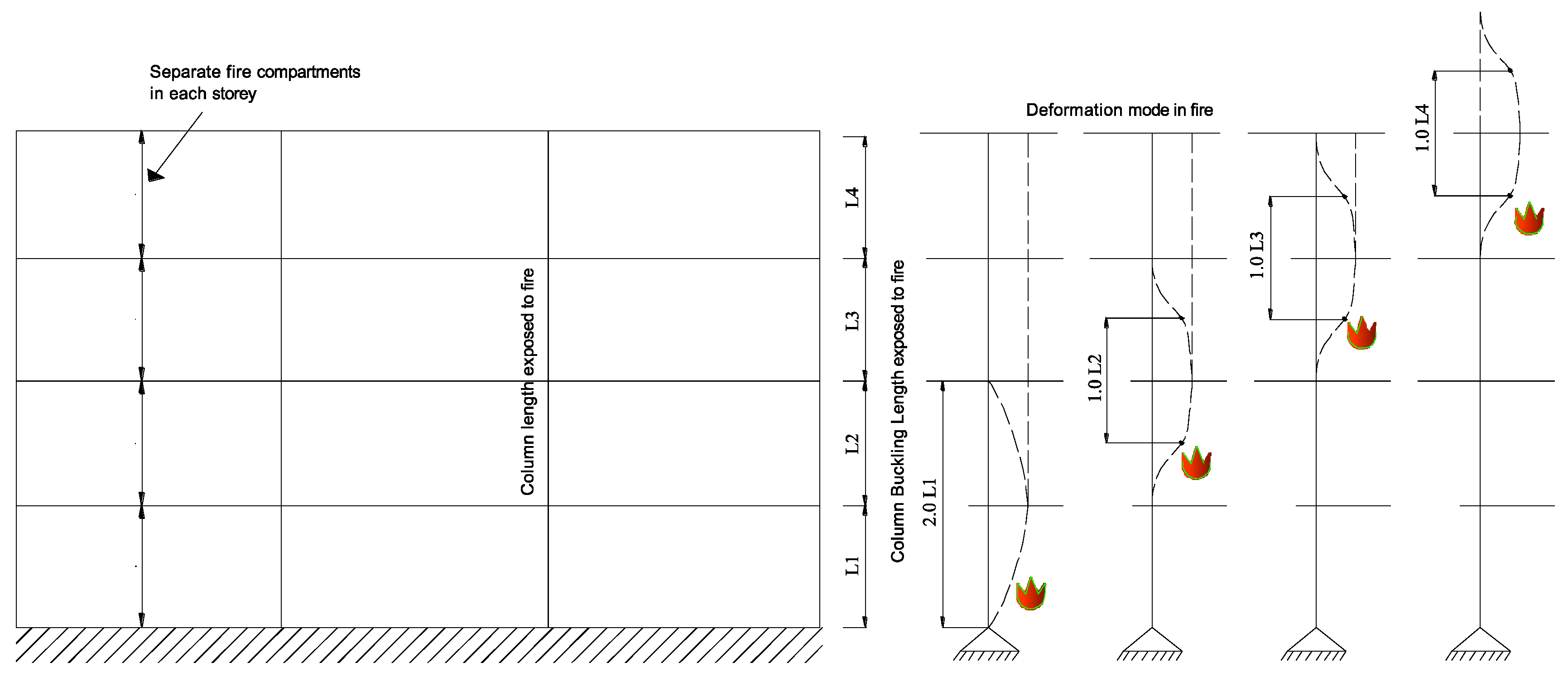
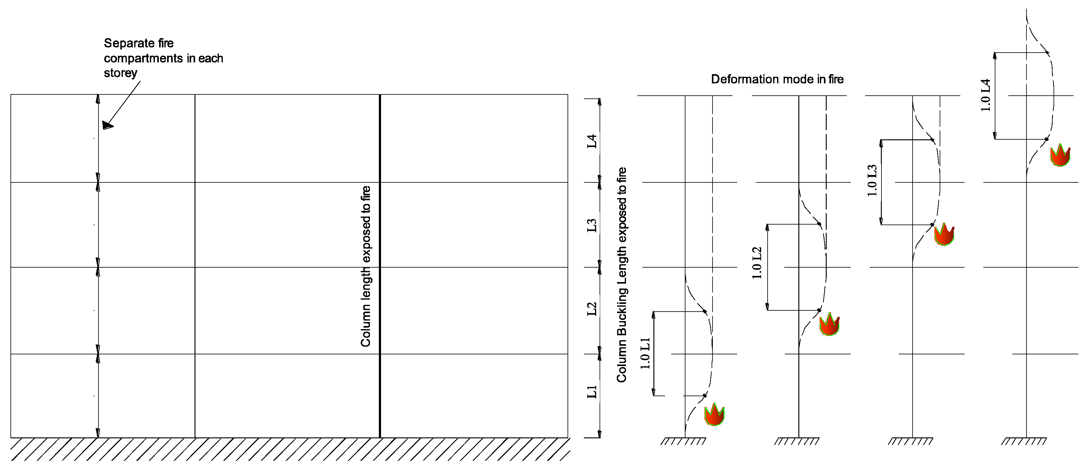
2.3. Methodology Used to Determine Buckling Lengths in Fire
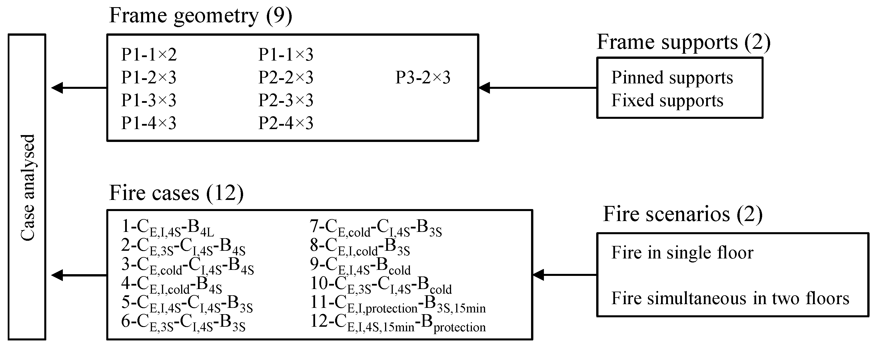
2.4. Determination of Fire Cases
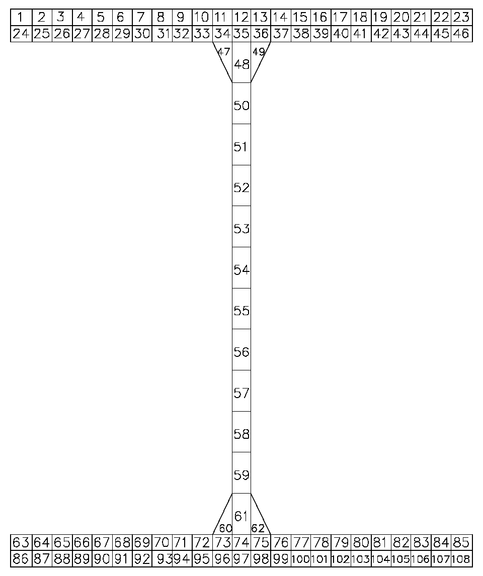
2.5. Methodology Used for Determination of Fire Resistance
3. Results and Discussion
3.1. Determination of the Buckling Coefficient
3.1.1. Critical Column of the Frame at 20 °C
3.1.2. Critical Column in Fire
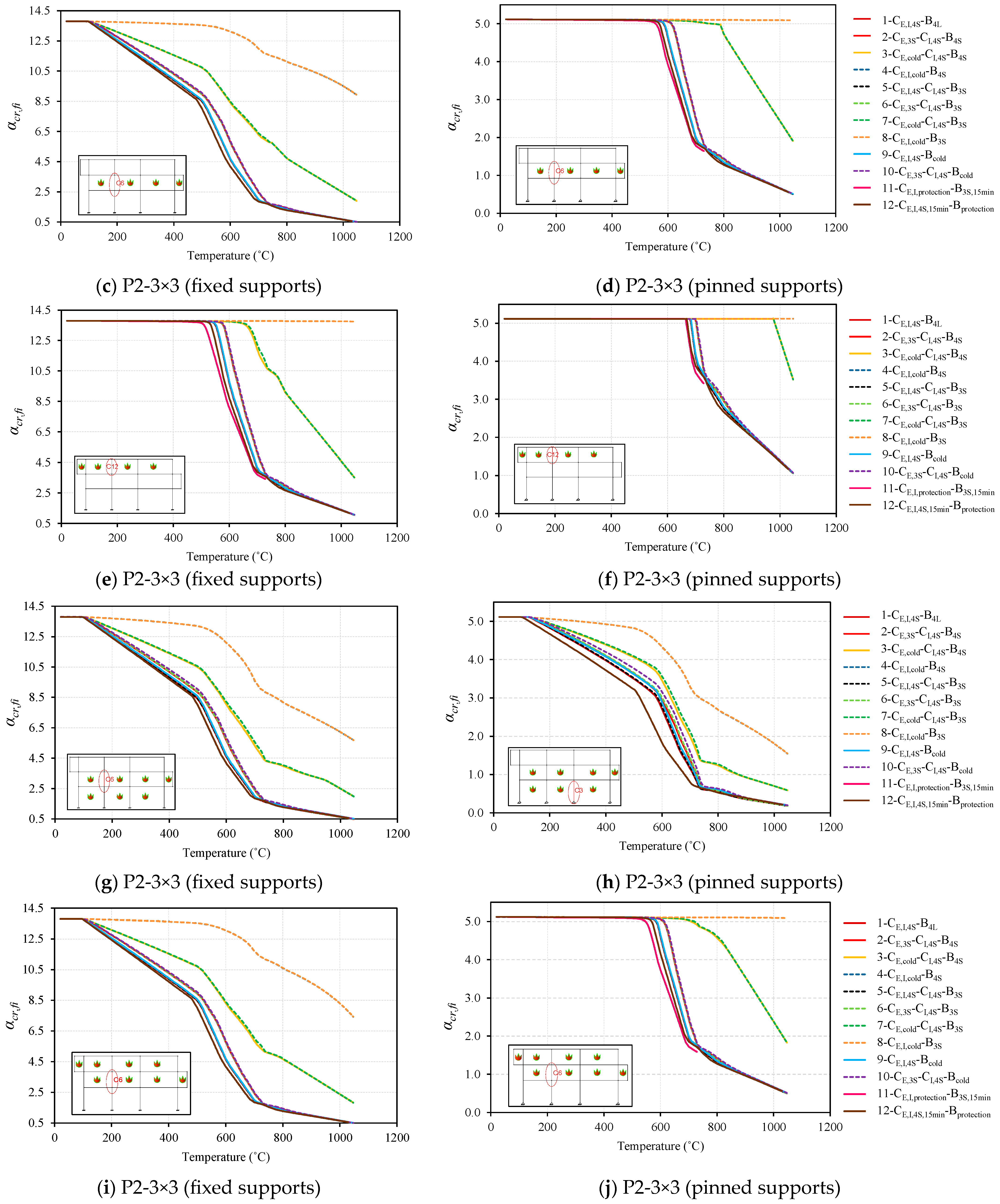
3.1.3. Critical Load Parameter in Fire
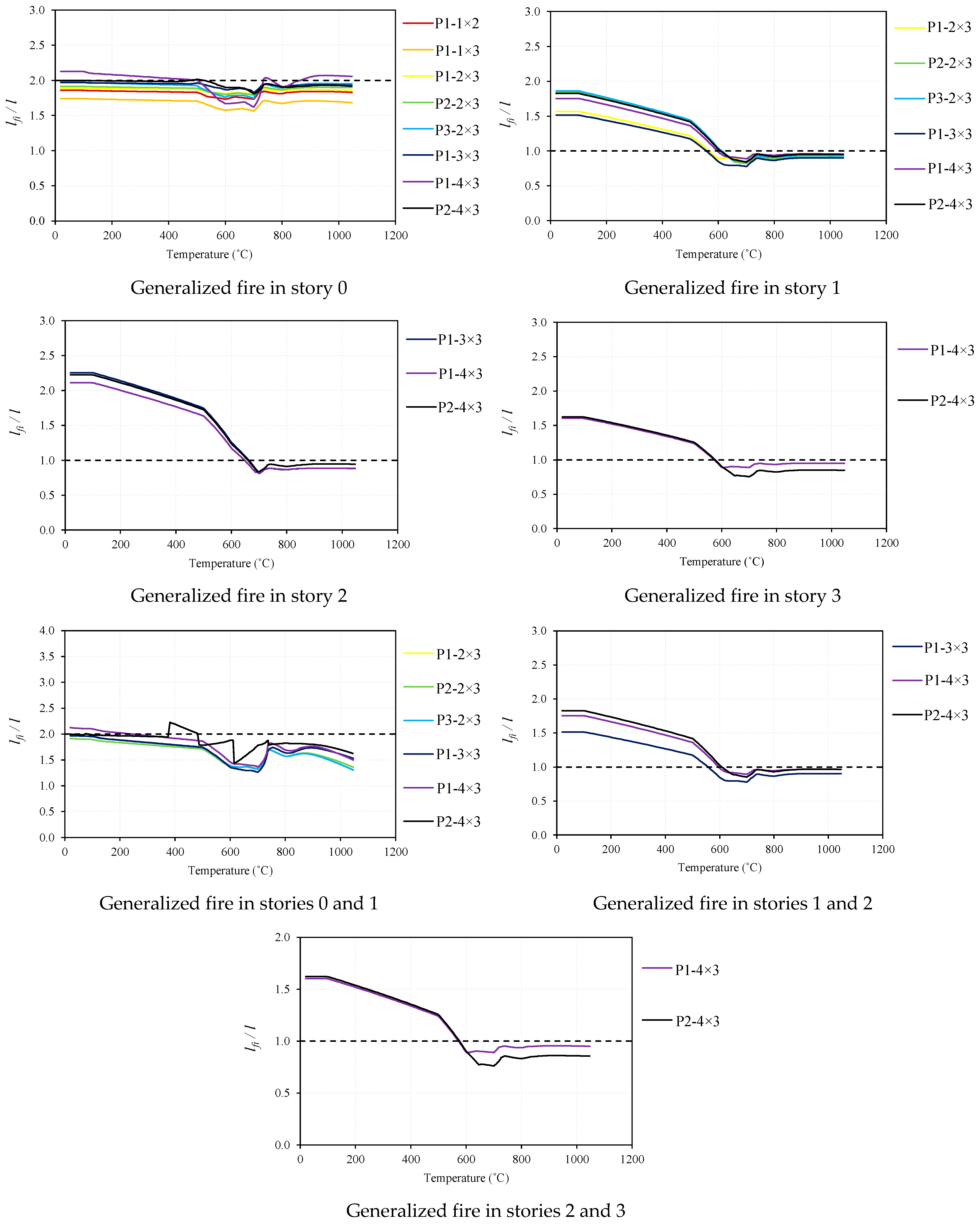
3.1.4. Buckling Lengths
Frame P2-3×3 with Fixed Supports for All Fire Cases
Frame P2-3×3 with Pinned Supports for All Fire Cases
Buckling Lengths for All Different Frames for Fire Case-6
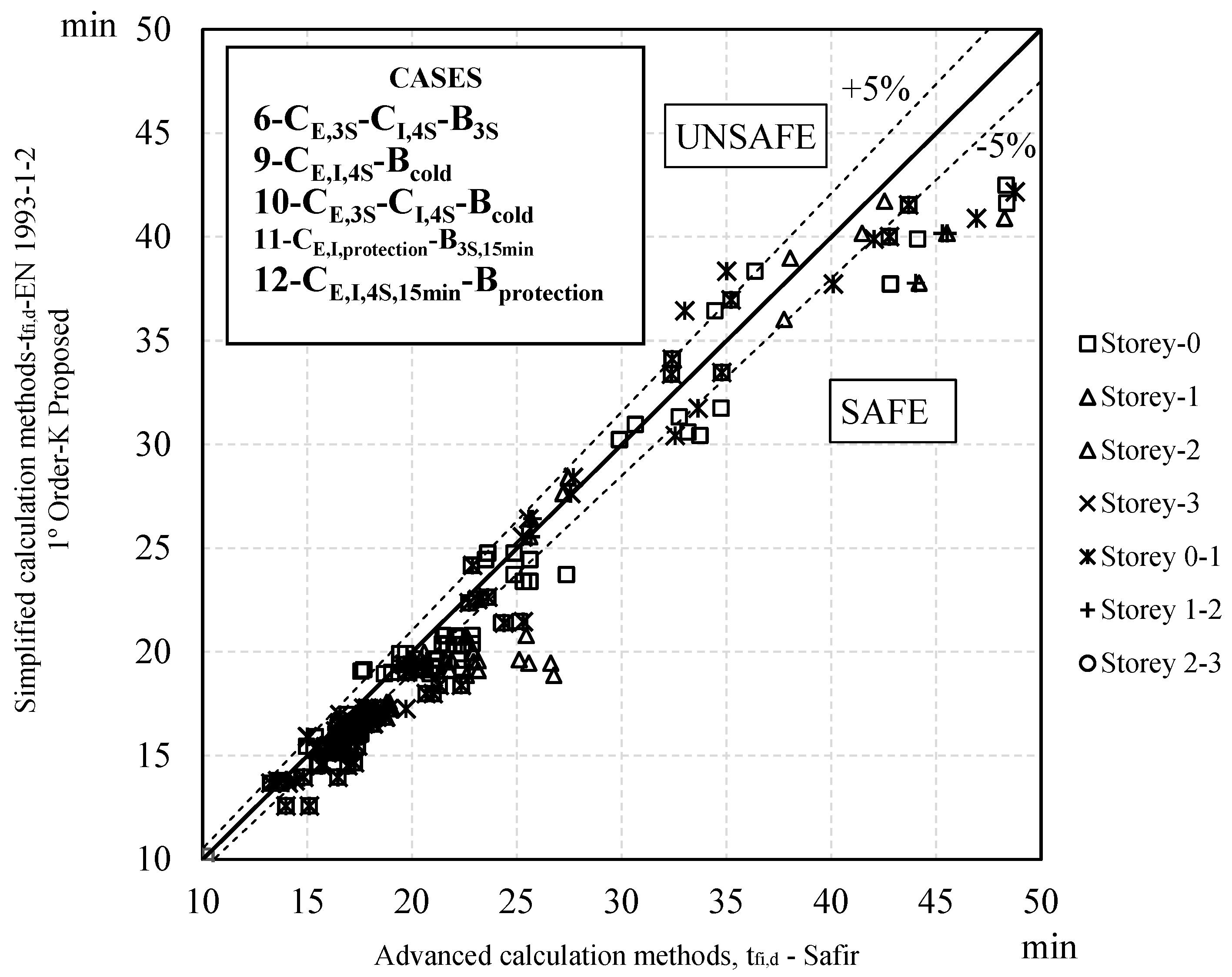
3.2. Fire Resistance Analysis
Fire Resistance Analysis for Various Fire Cases
4. Conclusions
- Through a linear buckling analysis that considers the effect of temperature on the reduction in steel stiffness, it was found that the critical load of a steel frame in fire decreases as a function of the increase in temperature. All steel frames studied in this research presented lateral displacement of their joints at some point during the fire. For that reason, the most consistent manner to classify steel structures in fire is into braced and unbraced structures. In this study, braced frames were considered by simply restraining the lateral displacements, and in real situations, such restraint should be provided by the bracing system. The influence of the fire and its impact on the bracing system might have a significant influence on the behavior of the frames in case of fire. Further studies on this particular matter should be carried out but are outside the scope of the present paper. The instability of the steel frame during fire is not always controlled by the critical column at normal temperature;
- With this study, we concluded that it is possible to propose approximate buckling lengths to verify the safety of regular and irregular unbraced steel frames. For cases 1, 2, 5, 6, 9, 10, 11, and 12 (defined in Section 2.4), fire was located in one story at a time or in two stories, simultaneously. For the columns in the ground story, it is recommended a buckling length of and for frames with fixed or pinned supports, respectively; for the remaining columns of the remaining stories, a buckling length of is suggested.
- It was observed that, for different geometries of steel frames (i.e., regular and irregular), as well as for various fire cases, the differences between the values of the buckling factors have not shown to be significant.
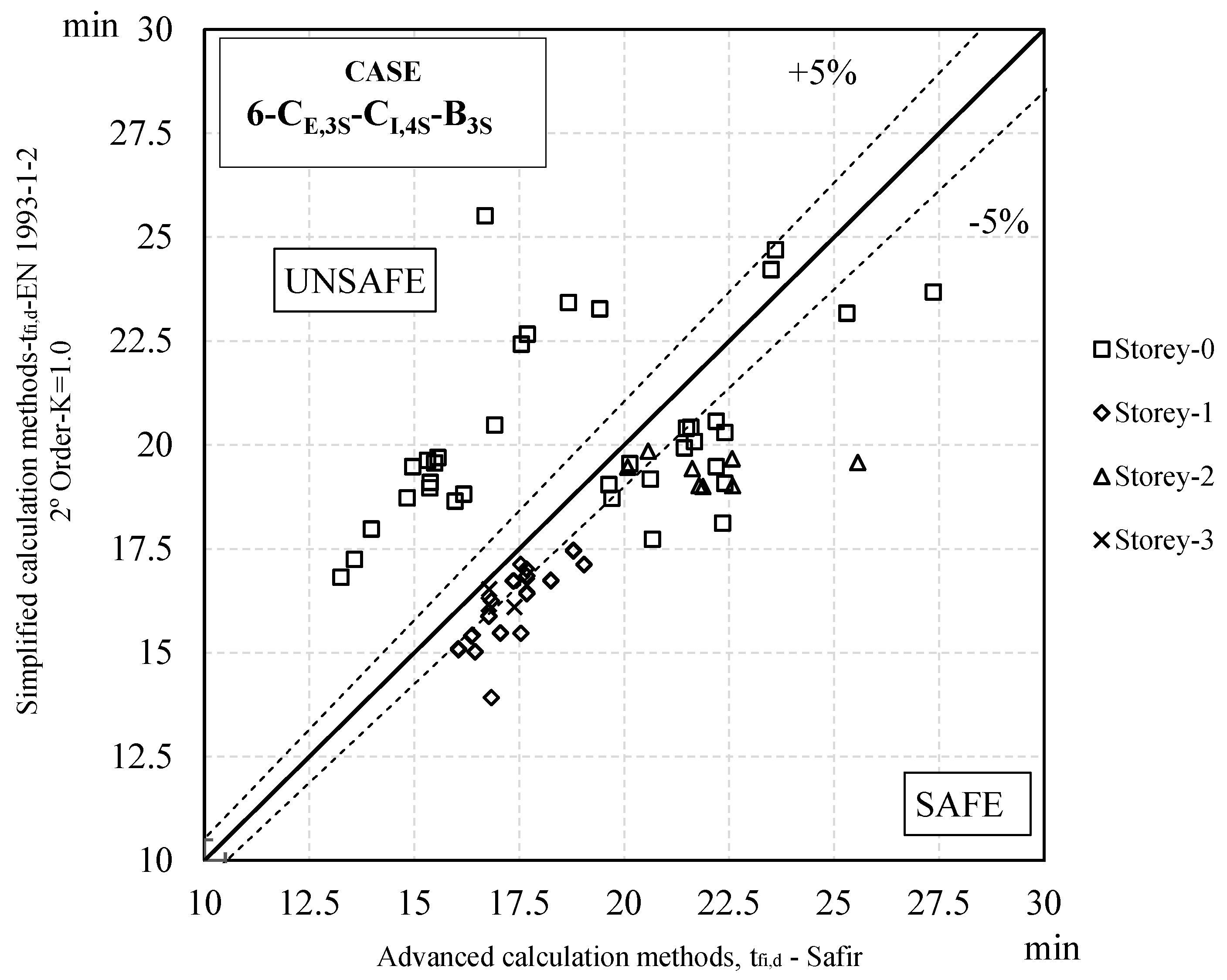
- Considering the second-order stresses calculated at room temperature and taking into account the respective geometrical imperfections for pinned frames, it was concluded that adopting a buckling coefficient of 1.0 yielded results outside safety parameters. Such conclusion is possible when compared with the advanced design method. Therefore, such buckling coefficients used in case of fire are not recommended.
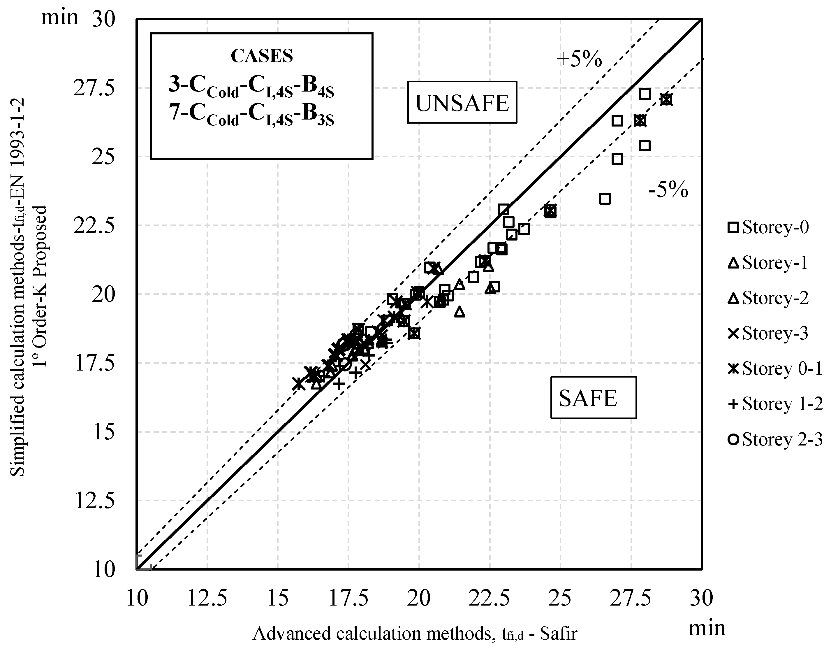
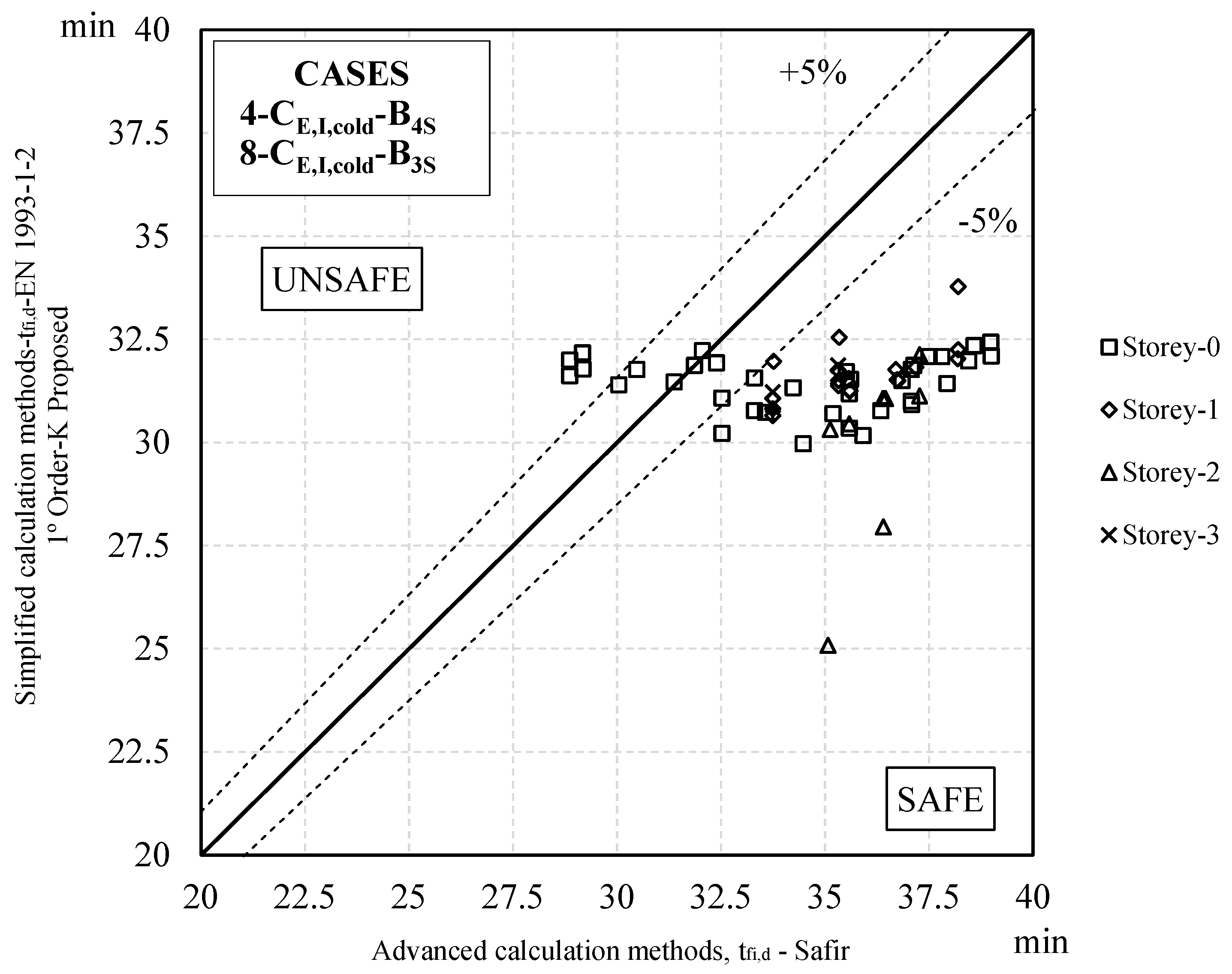
- Finally, it follows that a global first-order analysis of steel frames in fire without including the effects of imperfections in the verification of an equivalent column in relation to buckling phenomena and considering buckling lengths corresponding to the global mode of instability of the structure in fire is the best methodology for a simplified analysis of steel structures in fire.
Author Contributions
Funding
Data Availability Statement
Conflicts of Interest
References
- Franssen, J.-M.; Vila Real, P. Fire Design of Steel Structures; ECCS; Ernst & Sohn: Berlin, Germany, 2010; ISBN 9789291470990. [Google Scholar]
- CEN EN 1993-1-1; Eurocode 3: Design of Steel Structures—Part 1-1: General Rules and Rules for Buildings. CEN: Brussels, Belgium, 2005.
- Simões da Silva, L.; Simões, R.; Gervásio, H. Design of Steel Structures Eurocode 3: Design of Steel Structures; Part 1-1: General Rules and Rules for Buildings; Ernst: Berlin, Germany, 2010; ISBN 9783433029732. [Google Scholar]
- Bureau, A.; Snijder, H.H.; Knobloch, M.; Kuhlmann, U.; Gardner, L.; Taras, A.; da Silva, L.S. Revision of EN 1993-1-1—Design Rules for Structural Analysis, Cross-sectional Resistance and Member Buckling. Steel Constr. 2022, 15, 202–212. [Google Scholar] [CrossRef]
- Couto, C.; Vila Real, P.; Lopes, N.; Rodrigues, J.P. Buckling Analysis of Braced and Unbraced Steel Frames Exposed to Fire. Eng. Struct. 2013, 49, 541–559. [Google Scholar] [CrossRef]
- Talebi, E.; Md Tahir, M.; Zahmatkesh, F.; Kueh, A.B.H. Comparative Study on the Behaviour of Buckling Restrained Braced Frames at Fire. J. Constr. Steel Res. 2014, 102, 1–12. [Google Scholar] [CrossRef]
- Silva, T.; Carić, M.; Couto, C.; Vila Real, P.; Lopes, N.; Skejic, D. Buckling Analysis of Steel Frames Exposed to Natural Fire Scenarios. Structures 2017, 10, 76–88. [Google Scholar] [CrossRef]
- Rackauskaite, E.; El-Rimawi, J. A Study on the Effect of Compartment Fires on the Behaviour of Multi-Storey Steel Framed Structures. Fire Technol. 2015, 51, 867–886. [Google Scholar] [CrossRef]
- Xu, L.; Ma, T.; Zhuang, Y. Storey-Based Stability of Unbraced Structural Steel Frames Subjected to Variable Fire Loading. J. Constr. Steel Res. 2018, 147, 145–153. [Google Scholar] [CrossRef]
- Skowrofiski, W. Plastic Load Capacity and Stability of Frames in Fire. Science 1997, 19, 764–771. [Google Scholar]
- Toh, B.W.S.; Tan, K.H.; Fung, T.C. Strength and Stability of Steel Frames in Fire: Rankine Approach. Manager 2001, 127, 461–469. [Google Scholar] [CrossRef]
- Li, G.Q.; He, J.L.; Jiang, S.C. Fire-Resistant Experiment and Theoretical Calculation of a Steel Beam. China Civ. Eng. J. 2000, 32, 23–26. [Google Scholar]
- Liu, T.C.; Fahad, M.; Davies, J. Experimental Investigation of Behaviour of Axially Restrained Steel Beams in Fire. J. Constr. Steel Res. 2002, 58, 1211–1230. [Google Scholar] [CrossRef]
- Shepherd, P.G.; Burgess, I.W. On the Buckling of Axially Restrained Steel Columns in Fire. Eng. Struct. 2011, 33, 2832–2838. [Google Scholar] [CrossRef]
- CEN EN 1993-1-2; Eurocode 3: Design of Steel Structures—Part 1-2: General Rules–Structural Fire Design. CEN: Brussels, Belgium, 2005.
- ABNT NBR 14323; Projeto de Estruturas de Aço e de Estruturas Mistas de Aço e Concreto de Edifícios em Situação de Incêndio. Associação Brasileira de Normas Técnicas: São Paulo, SP, Brazil, 2013.
- Gomes, F.; Providência e Costa, P.; Rodrigues, J.; Neves, I. Buckling Length of a Steel Column for Fire Design. Eng. Struct. 2007, 29, 2497–2502. [Google Scholar] [CrossRef]
- Ma, T.; Xu, L. Storey-Based Stability of Unbraced Steel Frames under Piece-Linear Temperature Distributions. Eng. Struct. 2019, 194, 147–160. [Google Scholar] [CrossRef]
- Xu, L.; Zhuang, Y. Storey Stability of Unbraced Steel Frames Subjected to Non-Uniform Elevated Temperature Distribution. Eng. Struct. 2014, 62–63, 164–173. [Google Scholar] [CrossRef]
- Cao, Y.; Jiang, J.; Lu, Y.; Chen, W.; Ye, J. Progressive Collapse of Steel Structures Exposed to Fire: A Critical Review. J. Constr. Steel Res. 2023, 207, 107985. [Google Scholar] [CrossRef]
- Li, G.-Q.; Ji, W.; Feng, C.-Y.; Wang, Y.; Lou, G.-B. Experimental and Numerical Study on Collapse Modes of Single Span Steel Portal Frames under Fire. Eng. Struct. 2021, 245, 112968. [Google Scholar] [CrossRef]
- Venkatachari, S.; Kodur, V.K.R. System Level Response of Braced Frame Structures under Fire Exposure Scenarios. J. Constr. Steel Res. 2020, 170, 106073. [Google Scholar] [CrossRef]
- Venkatachari, S.; Kodur, V.K.R. Effect of Transient Creep on Fire Induced Instability in Steel Framed Structures. J. Constr. Steel Res. 2021, 181, 106618. [Google Scholar] [CrossRef]
- Gernay, T.; Elhami Khorasani, N.; Garlock, M. Fire Fragility Curves for Steel Buildings in a Community Context: A Methodology. Eng. Struct. 2016, 113, 259–276. [Google Scholar] [CrossRef]
- Gernay, T.; Khorasani, N.E.; Garlock, M. Fire Fragility Functions for Steel Frame Buildings: Sensitivity Analysis and Reliability Framework. Fire Technol. 2019, 55, 1175–1210. [Google Scholar] [CrossRef]
- Risco, G.V.; Zania, V.; Giuliani, L. Numerical Assessment of Post-Earthquake Fire Response of Steel Buildings. Saf. Sci. 2023, 157, 105921. [Google Scholar] [CrossRef]
- Pang, S.; Kodur, V.; Wang, W. Fire Resistance of Steel Structures, Incorporating HSS—Review and Recommendations. J. Constr. Steel Res. 2024, 217, 108677. [Google Scholar] [CrossRef]
- SAP2000 V14.0.0: Integrated Software for Structural Analysis and Design; CSI: Berkeley, CA, USA, 1995.
- CEN EN 1990; Eurocode—Basis of Structural Design. CEN: Brussels, Belgium, 2002.
- EN 1991-1-1; Eurocode 1: Actions on Structures—Part 1-1: General Actions—Densities, Self-Weight, Imposed Loads for Buildings. CEN: Brussels, Belgium, 2002.
- Vila Real, P.; Franssen, J.-M. Elefir-EN V1.4.5. Software for Fire Design of Steel Structural Members According the Eurocode 3. 2011. Available online: http://elefiren.web.ua.pt (accessed on 26 June 2015).
- CEA CAST 3M Is a Research FEM Environment; Its Development Is Sponsored by the French Atomic Energy Commission. 2015. Available online: http://www-cast3m.cea.fr/ (accessed on 26 June 2015).
- ISO 834-1:1999; Fire-resistance tests—Elements of building construction—Part 1: General requirements. International Organization for Standardization: Geneva, Switzerland, 1999.
- Franssen, J.-M.; Gernay, T. Modeling Structures in Fire with SAFIR: Theoretical Background and Capabilities. J. Struct. Fire Eng. 2017, 8, 300–323. [Google Scholar] [CrossRef]


| Load Combination | Accidental Combination |
|---|---|
| Combination 1 | |
| Combination 2 |
| Fire Case | Designation | Heating Scheme | ||
|---|---|---|---|---|
| External Column | Internal Column | Beam | ||
| Case 1 | CE,I,4S-B4S |  |  |  |
| Case 2 | CE,3S-CI,4S-B4S |  |  |  |
| Case 3 | CE,cold-CI,4S-B4S |  |  |  |
| Case 4 | CE,I,cold-B4S |  |  |  |
| Case 5 | CE,I,4S-B3S |  |  |  |
| Case 6 | CE,3S-CI,4S-B3S |  |  |  |
| Case 7 | CE,cold-CI,4S-B3S |  |  |  |
| Case 8 | CE,I,cold-B3S |  |  |  |
| Case 9 | CE,I,4S-Bcold |  |  |  |
| Case 10 | CE,3S-CI,4S-Bcold |  |  |  |
| Case 11 | CE,I, Protection-B3L,15min |  |  | 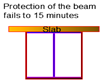 |
| Case 12 | CE,I, 15min-B Protection | 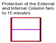 | 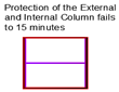 |  |
| Critical Instability Mode | ||
|---|---|---|
| Frame | Fixed | Pinned |
| P2-3×3 | 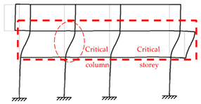 |  |
| Story | Column | Profile | E [kN/mm2] | Iy [mm4] | L [mm] | Ncr [kN] | NEd [kN] | ɳ |
|---|---|---|---|---|---|---|---|---|
| 0 | C1 | HE300A | 210 | 182,600,000 | 5000 | 15,138 | 518.4 | 3.42% |
| C2 | HE300A | 210 | 182,600,000 | 5000 | 15,138 | 748.0 | 4.94% | |
| C3 | HE320A | 210 | 229,300,000 | 5000 | 19,010 | 943.8 | 4.96% | |
| C4 | HE300A | 210 | 182,600,000 | 5000 | 15,138 | 628.8 | 4.15% | |
| 1 | C5 | HE200A | 210 | 36,920,000 | 3500 | 6247 | 409.6 | 6.56% |
| C6 | HE200A | 210 | 36,920,000 | 3500 | 6247 | 487.8 | 7.81% | |
| C7 | HE220A | 210 | 54,100,000 | 3500 | 9153 | 637.9 | 6.97% | |
| C8 | HE200A | 210 | 36,920,000 | 3500 | 6247 | 383.2 | 6.13% | |
| 2 | C11 | HE200A | 210 | 36,920,000 | 3500 | 6247 | 204.0 | 3.27% |
| C12 | HE200A | 210 | 36,920,000 | 3500 | 6247 | 242.6 | 3.88% | |
| C13 | HE220A | 210 | 54,100,000 | 3500 | 9153 | 327.2 | 3.57% | |
| C14 | HE200A | 210 | 36,920,000 | 3500 | 6247 | 144.3 | 2.31% |
| Generalized Fire | Cases | Critical Instability Mode | |
|---|---|---|---|
| Fixed | Pinned | ||
| Story 0 | 1, 2, 5, 6, 11, and 12 |  | 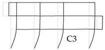 |
| 3 and 7 | 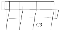 | ||
| 9 and 10 | 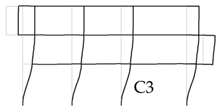 | ||
| Story 1 | 1, 2, 5, 6, 11, and 12 | 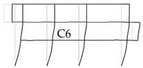 |  |
| 3 and 7 |  | ||
| 9 and 10 |  | ||
| Story 2 | 1, 2, 5, 6, 11, and 12 |  | 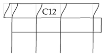 |
| 3 and 7 |  | 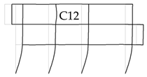 | |
| 9 and 10 | 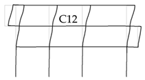 |  | |
| Story 0 and 1 | 1, 2, 5, 6, 11, and 12 | 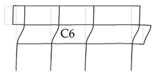 |  |
| 3 and 7 | |||
| 9 and 10 | |||
| Story 1 and 2 | 1, 2, 5, 6, 11, and 12 | 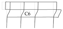 |  |
| 3 and 7 |  | ||
| 9 and 10 |  | ||
| Frame | Generalized Fire | Fixed | Pinned | ||
|---|---|---|---|---|---|
| Column | Profile | Column | Profile | ||
| P2-3×3 | 0 | C3 | HE320A | C3 | HE320A |
| 1 | C6 | HE200A | C6 | HE200A | |
| 2 | C12 | HE200A | C12 | HE200A | |
Disclaimer/Publisher’s Note: The statements, opinions and data contained in all publications are solely those of the individual author(s) and contributor(s) and not of MDPI and/or the editor(s). MDPI and/or the editor(s) disclaim responsibility for any injury to people or property resulting from any ideas, methods, instructions or products referred to in the content. |
© 2024 by the authors. Licensee MDPI, Basel, Switzerland. This article is an open access article distributed under the terms and conditions of the Creative Commons Attribution (CC BY) license (https://creativecommons.org/licenses/by/4.0/).
Share and Cite
Silva, T.; Couto, C.; Vila Real, P.; Lopes, N. Parametric Study on the Buckling of Unbraced Steel Frames under Fire Situation. Appl. Sci. 2024, 14, 5709. https://doi.org/10.3390/app14135709
Silva T, Couto C, Vila Real P, Lopes N. Parametric Study on the Buckling of Unbraced Steel Frames under Fire Situation. Applied Sciences. 2024; 14(13):5709. https://doi.org/10.3390/app14135709
Chicago/Turabian StyleSilva, Thiago, Carlos Couto, Paulo Vila Real, and Nuno Lopes. 2024. "Parametric Study on the Buckling of Unbraced Steel Frames under Fire Situation" Applied Sciences 14, no. 13: 5709. https://doi.org/10.3390/app14135709