Article

Research on the Reasonable Width of Coal Pillar Driving along Goaf under Thick Hard Roof

State Key Laboratory of Coal Resources and Safe Mining, China University of Mining and Technology, Xuzhou 221116, China
*
Author to whom correspondence should be addressed.
Appl. Sci. 2024, 14(14), 6381; https://doi.org/10.3390/app14146381
Submission received: 20 June 2024 / Revised: 16 July 2024 / Accepted: 19 July 2024 / Published: 22 July 2024
(This article belongs to the Section Civil Engineering)

Abstract

:
There are fewer studies on the width of coal pillar retaining under a thick, hard roof. This paper takes the thick limestone roof in the 10110 working face of Jinniu Coal Mine as the background, taking the reasonable coal pillar width and its stability control technology as research objectives. Taking the theoretical analysis and calculation, numerical simulation to study the stress distribution along goaf under different parameters of the roof cutting, the stress distribution of the roadway, and displacement of the surrounding rock under different coal pillar widths, finally examined through on-site industrial experiments. The results show that (1) the vertical stress along goaf shows a gradual decrease with the increase of the roof cutting height and angle; after considering the cost and the difficulty, the optimal height and angle are chosen to be 21 m and 15°; (2) the vertical peak stress of coal pillar decreases with the increase of the width, coal pillar is gradually transformed from the crushed state to the elastic state, the displacement of the roadway also decreases with the increase of the width of the pillar, and the width of the coal pillar is chosen to be 8.0 m after comprehensive analysis; (3) during the roadway excavation and working face mining, the deformation of the surrounding rock is in a reasonable range, and the anchors and bolts are in a good state of stress, which indicates that retaining 8 m coal pillar is a success. This paper also provides theoretical references and implications for coal pillar retaining in similar geological mining conditions.

1. Introduction

Coal resources are an important support for China’s primary consumption energy, in recent years, coal production has continued to increase, thus maintaining the national energy security. In the process of coal mining, it is usually necessary to retain a certain width of coal pillar between adjacent working faces [1,2]. Maintaining wide coal pillars will result in a significant waste of coal resources, which not only decreases the resource recovery rate but also reduces the economic income of the mine. Therefore, maintaining a reasonable width of the coal pillar is of great significance [3]. Accompanied by the innovation of coal mining technology, driving along the goaf has been very widely used in many mines because of its simple process, low deformation of the roadway, small amount of auxiliary transportation, and so on [4,5,6,7].
Numerous scholars have proposed methods for calculating the width of coal pillars under different geological conditions. Huo Bingjie et al. [8] took the extra-thick coal with a hard roof in Datong mine as the engineering background, theoretically deduced the width of the internal stress field of the coal pillar under the multi-layer hard roof, and calculated the reasonable width of the coal pillar is 6 m. Liu Zhen et al. [9] used the limit equilibrium theory, the theory of gradual destruction of the coal pillar, and the theory of the slip line to calculate the width of the coal pillar under the slicing mining and determined the layout form of the roadway. Zhao Jie [10], in response to the difficulty of coal pillars retaining under hard roof island mining conditions, deduced a set of supporting stress calculation formulas applicable and utilized finite element and finite-discrete element calculation methods to obtain the reasonable size of coal pillars. Xu Lei et al. [11] used a three-dimensional discrete element numerical simulation method to research the effects of roof cutting angle, the width of coal pillar, and the change of these parameters on the mechanical properties of coal rock in the working face and determined the optimal roof cutting angle and the width of coal pillar according to simulation results. Yuan Zhang et al. [12] revealed the roadway deformation law of small coal pillars driving along goaf and, based on the trinity coupling support technology, proposed a comprehensive control method of surrounding rock. Guanjun Li et al. [13] proposed a comprehensive rock strata control method combining roadway expansion, long anchor cable, and blasting roof cutting to solve the asymmetric deformation of the roadway driving along goaf under the action of main roof dynamic load. Jiping Yang et al. [14] proposed a new method of surrounding rock control technology based on the difference in the support conditions of the roadway roof, solid coal seam, and the narrow coal pillar in the roadway driving along goaf. Based on the above analysis, it can be seen that by adopting suitable coal pillar width calculation methods and reasonable surrounding rock control technology, the roadway driving along the goaf has been applied under many hard roof conditions. Compared with a hard roof, a thick hard roof generally refers to the overlying rock layer on the working face with the characteristics of large thickness, high hardness, and structural integrity [15,16,17,18]. In the process of mining, the roof is generally difficult to fall, which will cause a large area of overhanging roof [19,20,21]. The roof collapse will apply a large impact load, which is very prone to cause various dynamic disasters [21,22,23]. Dongdong Qing et al. [24] studied the acoustic emission characteristics of thick sandstone roof specimens under uniaxial compression and its crack extension law in order to deal with the problem of thick hard roofs affecting the safety of the working face. Bosheng Hu et al. [25] investigated the application of close-hole roof-cutting technology in a thick hard roof, determined the optimal parameters, and proposed a dynamic pressure mitigation strategy. Chen Li et al. [26] proposed the use of hydraulic fracturing to cut off the key rock strata to reduce the high surrounding rock stress from the hard roof. Jingzhong Zhu et al. [27] investigated the effect of hydraulic fracturing on the control of thick, hard roofs and analyzed the damage characteristics of overburdened rock with and without fracturing. Zhu Li et al. [28] investigated the effect of ground hydraulic fracturing on the decompression of a hard roof working face and proposed a numerical simulation method of “separation + interface” was proposed. However, there are fewer studies on the width of coal pillars driving along goaf under the thick and hard roof, and there is also a lack of reference cases of roadway excavation.
Based on this, this paper takes the 11.62 m k2 limestone in the 10110 working face of Jinniu Mine as the engineering background and carries out the research on the width of the coal pillar driving along goaf under a thick, hard roof. Firstly, the optimal parameters for roof cutting and pressure relief at the side of the goaf were calculated theoretically, and the range of coal pillar width was derived by combining the theory of ultimate strength of the coal pillar and the theory of coal pillar load calculation. Then, the distribution of stress in the surrounding rock and deformation of the roadway under different roof-cutting parameters and the width of the coal pillar were analyzed by numerical simulation, and the optimal roof-cutting parameter and coal pillar width were determined accordingly. Finally, on-site industrial practice is adopted to observe the displacement of the roadway and the force of cable (bolt) to determine the feasibility of a coal pillar setting. This paper not only provides theoretical guidance for the coal pillar width retaining in the 10110 working faces of Jinniu Mine but also provides a reference case for coal pillar retaining under similar geological mining conditions.

2. Project Overview

Jinniu Coal Mine is located in Tumen Town, Yaodu District, Linfen City, Shanxi Province as shown in Figure 1a,b, with a mining area of 15.0208 km2, production capacity of 900,000 t/a, and mining depth of 799.92~1229.92 m. The north of the 10110 working face is the 10112 working face, the south is the 10108 working face, the west is the district rise, and the east is the boundary coal pillar of the mine. The strike length of the working face is 200 m, the advance length is 1369 m, the thickness of the coal is 3.8~7.7 m, and the average thickness is 5.1 m, the working face layout is shown in Figure 1c. The working face adopts the method of comprehensive coal caving mining; the mining height is 2.8 m, the height of the coal caving is 2.34 m, the depth of the working face is 250 m, the inclination angle of the coal is 3~12°, and the average is 6°. The immediate roof of the working face is k2 limestone of 11.62 m, with an average compressive strength of 111.5 MPa, average tensile strength of 3.29 MPa, and average shear strength of 8.18 MPa, which is a stable roof. The thickness of the coal is 5.1 m, with a compressive strength of 16.3 MPa; the main roof is 3.29 m black mudstone, with a uniaxial tensile strength of 0.58 MPa; the immediate floor is 5.51 m of gray–white bauxite and the main floor is 5.11 m of fine mudstone, the histogram of the working face is shown in Figure 1d.
In the process of working face mining, the thick, hard roof will form a large-span cantilever beam, which leads to a large amount of energy accumulation in the rock mass. After reaching the limit, it will result in a strong dynamic pressure manifestation, including roof subsidence, floor heave, and hydraulic support damage, which seriously affects the safe production of the mine [18,29].

3. Method

3.1. Analysis of Roof Cutting Pressure Relief in the Goaf

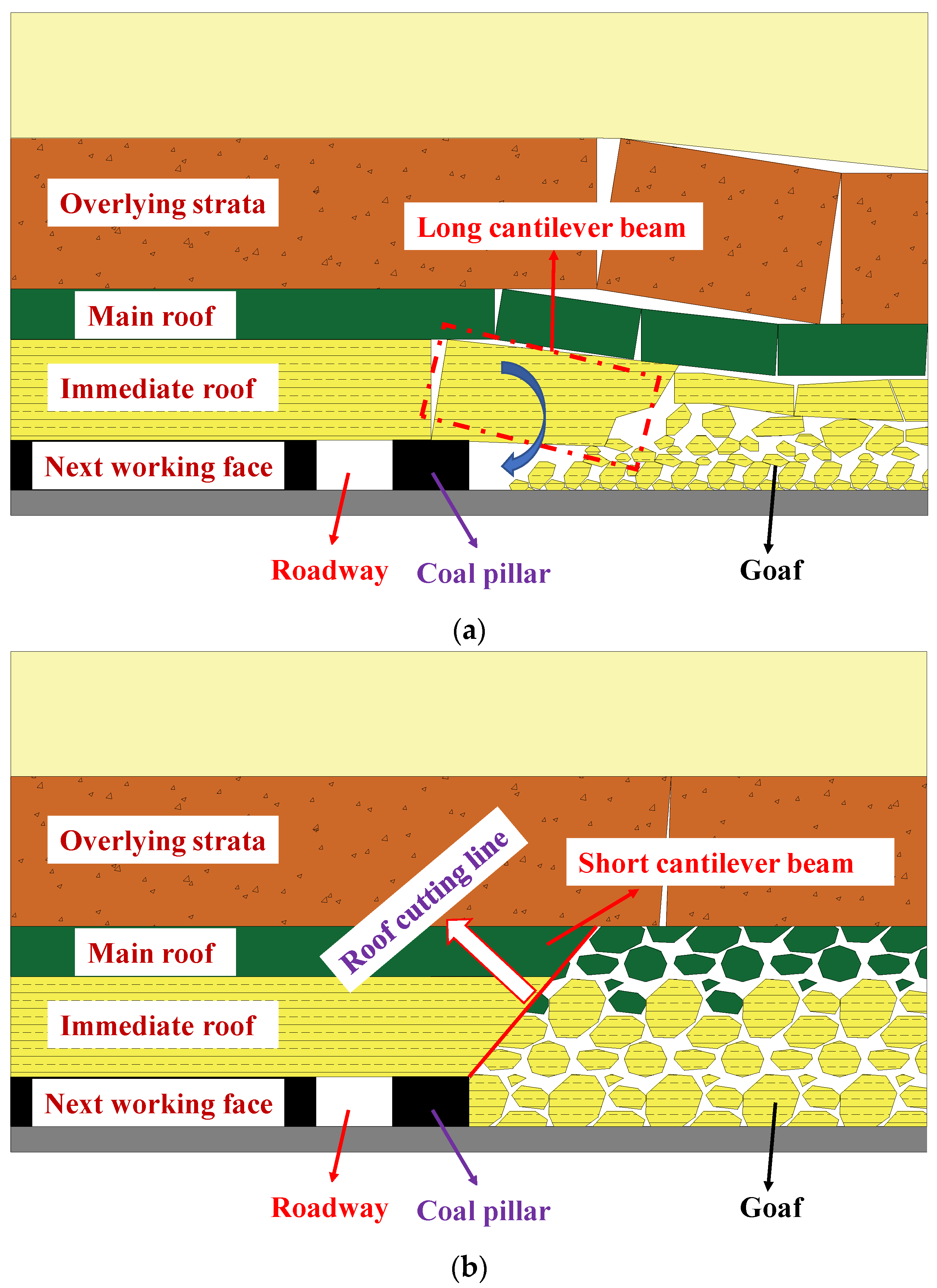
Due to the large thickness and high strength of the roof, the immediate roof overhanging is very large and difficult to collapse, which leads to a large stress concentration in the small coal pillar and the roadway and ultimately will greatly increase the chance of the roadway to appear rib spalling, the roof fall, the stability of the roadway will have a negative impact. As shown in Figure 2a, due to the difficulty of the collapsing of the roof, it will also lead to the gangue not being directly filled with the goaf, which further aggravates the deformation of the surrounding rock [30].
The above problems can be solved by using the technique of pre-splitting blasting roof-cutting pressure relief, and the model of the overlying rock strata before and after roof cutting is as follows in Figure 2. As shown in Figure 2b, by pre-splitting blasting roof cutting in the upper section, the rock layer of the roof in the mining area is broken along the direction of pre-cracking, which not only makes the collapsed gangue fill up the mining area but also reduces the accumulation of the stress of the overhanging roof inside the small coal pillar, thus reducing the stress concentration inside the coal pillar, which is beneficial to the maintenance of the stability of the roadway.

3.2. Theoretical Calculation of the Parameters of the Roof Cutting Pressure Relief

3.2.1. Theoretical Calculation of Roof Cutting Depth

The depth of the roof cutting affects the stress reduction degree and determines whether the roof can completely collapse and fill the goaf after cutting, which also affects whether the overlying rock strata can be effectively carried by the gangue in the goaf. Reasonable cutting depth can ensure that the main roof collapses timely with the advancement of the working face, so that the goaf is filled timely by the collapsed rock [31,32]. The calculation formula is shown in the following Equation (2): Kp is the coefficient of rock fragmentation, the volume of the rock after fragmentation will increase compared with the overall state, the ratio of the rock volume in the loose state to the rock volume of solid state before fragmentation is called the coefficient of fragmentation, and  c 1  and  c 2  are the parameters related to the roof. The values are shown in Table 1.
K p = 1 + c 1 m + c 2 100
The empirical formula for the depth:
H = m K p 1
where: H—Minimum depth of roof cutting, m; m—mining height, 5.1 m;  K p —the coefficient of rock fragmentation, taken as 1.28.
Taking the data into the above formula shows that the minimum depth of cut top H is 18 m.

3.2.2. Theoretical Calculation of Roof Cutting Angle

In the process of roof cutting, it should be prevented from destroying the reserved coal pillar, and ensure that the coal pillar has sufficient bearing capacity; the angle of roof cutting is calculated as follows [33,34]:
β φ arctan 2 H 1 m η h 1 k p 1 L
where  H 1 —thickness of main roof, 3.29 m;  φ —friction angle between key blocks of the main roof, 45°; L—main roof span, 8.1 m; m—mining height, 5.1 m;  η —working face extraction rate, taken as 93%;  k p —the coefficient of rock fragmentation, taken as 1.28  h 1 —thickness of immediate roof, 11.62 m.
The data were brought into Equation (3), calculate the angle β ≤ 21°.

3.3. Theoretical Calculation of Coal Pillar Width under Thick Hard Roof

The strength and stability of the coal pillar are the primary consideration when determining the width; there are many empirical formulas for calculating the strength of a coal pillar [35], such as the Obert–Kwvall/Wang formula (applicable to coal pillars with width-to-height ratios of 1~8), the Holland formula [36] (applicable to coal pillars with width-to-height ratios of 2~8), the Salamon–Munro formula [37] and Bieniawski formula [38]. It is obvious that the first two formulas are not suitable for calculating the strength of coal pillars in this paper. The Salamon–Munro formula is usually used to calculate the strength of coal pillars in the stable state, and the Bieniawski formula is used to calculate the strength of coal pillars considering in situ situation [39,40,41]. In this paper, adopting the Bieniawski formula to calculate the ultimate strength of coal pillars is more appropriate; the formula is shown as follows:
σ p = σ m 0.64 + 0.36 B h
where  σ p —coal pillar strength, MPa;  σ m —uniaxial compressive strength of field sample, MPa; B—width of coal pillar, m; h—height of coal pillar, m.
The compressive strength of the sample used in the laboratory and the compressive strength of the field sample will differ due to the different stress environments they are subjected to. Based on Gaddg’s formula, Hustrulid gave a conversion formula for the uniaxial compressive strength of the laboratory sample and the uniaxial compressive strength of the field sample [42]:
σ m = 0.2357 σ c
where  σ c —uniaxial compressive strength of laboratory sample, MPa.
The average compressive strength of coal samples from Jinniu Mine is 16.3 MPa, the height of the coal pillar is 5.1 m, the diameter of the laboratory specimen is 50 mm or 0.05 m, which can be calculated by substituting into the above formula, the uniaxial compressive strength of on-site critical cube specimen  σ m  is 3.84 MPa.
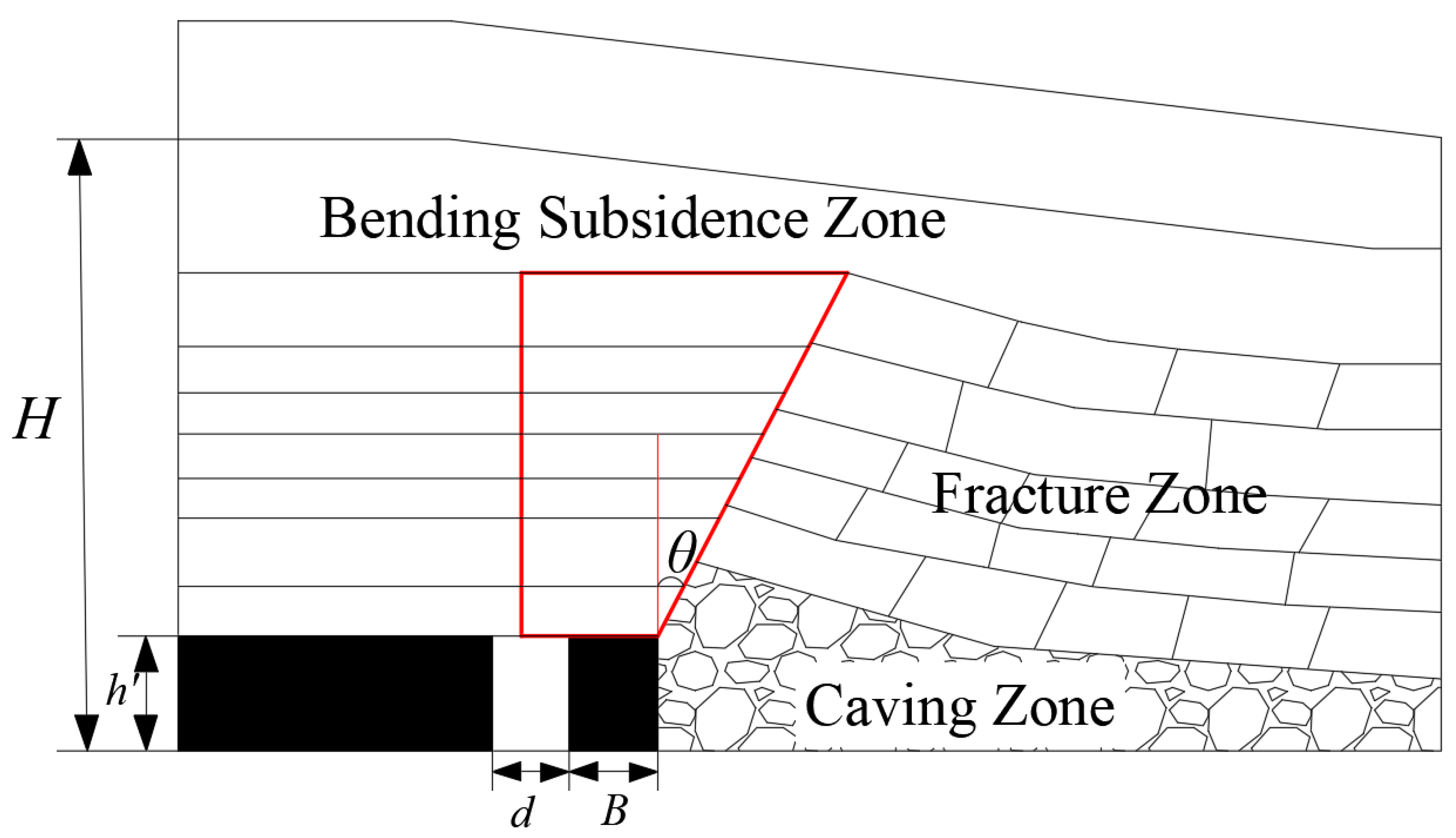
Calculation of load stress by the overlying rock strata of the coal pillar, the establishment of the coal pillar bearing model driving along goaf is shown in Figure 3 below, after the upper working face is mined back, according to the theory of masonry beams, the rock strata of the goaf is divided into caving zone, fracture zone, and bending subsidence zone. The rock strata above the coal pillar is an inverted step-like form; the angle between the edge of the inverted step and the plumb line is θ, which is called the lateral support angle. The load carried by the narrow coal pillar is the rock strata load in the red trapezoidal area shown in Figure 3, the width of the bottom of the trapezoid is the width of the coal pillar plus half of the width of the roadway, and the height of the trapezoid is the height of the fracture zone in the goaf minus the mining thickness of the working face [43].
The formula for calculating the stresses borne by the coal pillar is shown below:
σ s = d + 2 B + H h tan θ γ H h 2 B
where d—the roadway width, m; H—the height of the fracture zone (the calculated formula is shown in Table 2, the formula h is the height of mining), θ—Lateral support angle, °;  h —height of roadway, m;  γ —overlying rock mass, 0.025 N/mm2.
According to the project overview, it can be seen that the roof of Jinniu Coal Mine is k2 limestone, which belongs to the hard roof; it can be seen that the value of the height of the fracture zone in Jinniu Coal Mine is 53.9–71.7 m.
After mining the roadway along the goaf, to ensure the retaining coal pillar can still maintain its stability, the load borne by the coal pillar should not be greater than its maximum bearing capacity. When  σ s = σ p , the critical width of the coal pillar at the limit load can be found:
d + 2 B + H h tan θ γ H h 2 B = σ m 0.64 + 0.36 B h
According to the actual mining situation of the working face of Jinniu Coal Mine, the mining depth of the working face is 250 m, the capacity of the overlying rock layer  γ  takes 0.025 N/mm2, and the lateral support angle  θ  is 30°. The width of the roadway d is 4.8 m, the height of the roadway  h  is 3.2 m, the mining height of the coal h is 3.2 m, and the width of the roadway d is 4.8 m. The mining height of the coal h is 5.1 m, and the uniaxial compressive strength of the on-site sample  σ m is 3.84 MPa. After calculating by the above formula, the width of coal pillar B ranges from 7.08 m to 10.7 m, and the coal pillar has a bearing capacity above this width range. It is necessary to further determine the size of the coal pillar through the following analysis.

3.4. Numerical Simulation Program

3.4.1. Establishment of Numerical Model

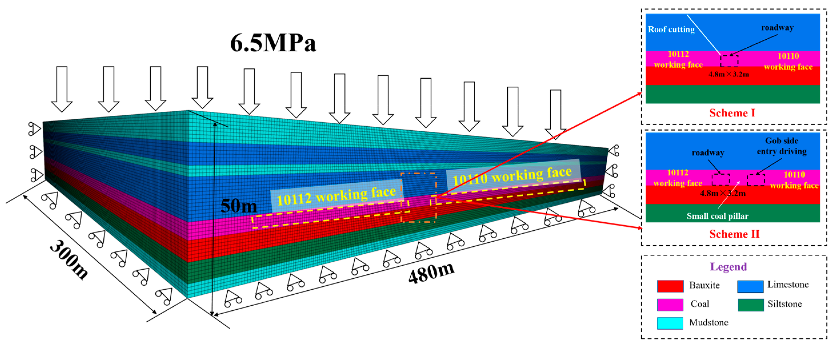
In order to determine the optimal parameters of the roof cutting and the width of the coal pillar in the Jinniu mine, the Flac3D numerical simulation model was established according to the geological condition of the working face and the roadway layout of the Jinniu mine. The dimensions of the model are 480 m × 300 m × 50 m, and the mining width of 10112 and 10110 working faces are both 200 m. Considering leaving a section width of coal pillars, 30 m of coal pillars are left on both sides of the model; the gravity of the overburden is simulated by applying loads on the top of the model, and the depth of the working face is 250 m, so the vertical stress load is 6.25 MPa; the boundary conditions of the four sides and the bottom units of the model are fixed by restricting the speed of the units, the horizontal lateral pressure coefficient of the model is taken as 1, and the horizontal load of 6.25 MPa is applied around the model to simulate the role of horizontal stress, the numerical model and its boundary diagram are shown in Figure 4; the intrinsic model of the stratum of the numerical calculation adopts the Mohr–coulomb model, simulate the mining and roadway excavation of the working face by setting the model as null.
The model parameters for this numerical simulation are shown in Table 3. Because of the large number of the same stratum in the model, each stratum is named separately in the numerical modeling, and the parameters are assigned according to the group name.

3.4.2. Numerical Simulation Scheme

(i) Numerical simulation program of the roof-cutting parameters
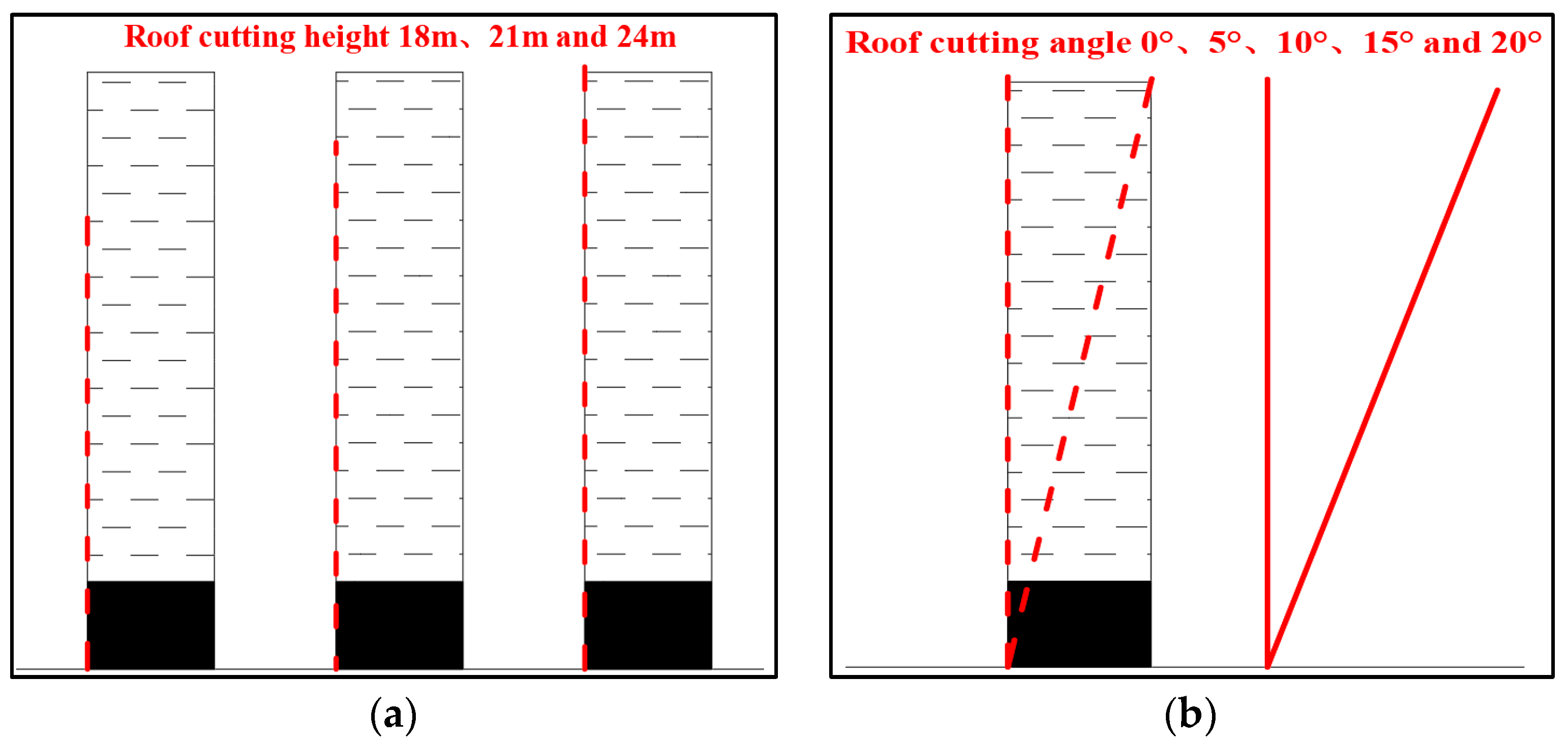
In order to explore the influence of the depth and angle of roof cutting on the stress in goaf, firstly, under the condition of the given roof cutting angle, research the change law of the vertical stress in goaf under different roof cutting heights to determine the optimal height. Then, based on determining the optimal height of the roof cutting, research the vertical stress change law in goaf under different roof cutting angles to determine the optimal angle. The numerical simulation scheme of roof-cutting parameters in the goaf is as follows in Figure 5. The optimal roof-cutting parameters are determined by the above simulation scheme.
(ii) Numerical simulation scheme for coal pillar width retaining
By combining the above roof-cutting parameters and the theoretical calculation of the coal pillar width, five coal pillar sizes for simulation and analysis are selected, as shown in Table 4. Under the premise of roof cutting and pressure relief in the goaf, the optimal width of the coal pillar is derived by simulating the stress and displacement of the roadway under different conditions of coal pillar width.

4. Results and Discussion

4.1. Numerical Simulation of Roof Cutting Parameters

The numerical simulation process of roof-cutting parameters is as follows: Establishment of numerical model → Assignment of parameters, ground stress balance → Excavation of 10112 working face → Excavation balance → Simulation of different roof-cutting parameters → Stress distribution after roof-cutting.

4.1.1. Stress Distribution along Goaf under Different Roof Cutting Heights

The stress distribution and stress curve along goaf under different roof-cutting heights are shown in Figure 6 and Figure 7 below:
It can be seen from the above Figure 6 and Figure 7:
(1) Under the condition of different cutting heights, the change law of vertical stress curves is the same; all show the trend of first gradually increasing to reach the maximum value of stress and then gradually decreasing to the initial stress;
(2) When the height of roof cutting is 18 m, the peak stress along goaf is 19.09 MPa, compared to roof is not cut, the peak stress after the roof cutting is reduced by 1.76 MPa, and the stress reduction rate is 8.44%; when the height of roof cutting is 21 m, the peak stress along goaf is 18.37 MPa, comparing with the roof is not cut, the peak stress after the roof cutting is reduced by 2.48 MPa, the stress reduction is 11.89%; when the height of the roof cutting is 24 m, the peak stress along goaf is 17.41 MPa, compared with the roof is not cut, the stress after the roof cutting is reduced by 3.44 MPa, the stress reduction is 16.5%.
According to the stress distribution curve along goaf, it can be seen that the stress concentration is the highest at a depth of 18 m, which indicates that the depth of the roof cutting fails to cut down the roof in goaf completely, and the effect of roof cutting is poor; the stress reduction is larger when the depth of the roof cutting is 21 m and 24 m, and the stress concentration of the coal body after the roof cutting is smaller, which indicates that the depth of the roof cutting cut down the roof in goaf effectively, and the effect of the roof cutting is good. The effect of roof cutting is better.
Combined with the comprehensive column diagram of the working face, it can be seen that the rock strata within 21 m above the coal are 11.62 m k2 limestone, 3.29 m mudstone, and 6.1 m limestone. The depth of the roof cutting is 21 m when the roof-cutting layer is located in the limestone layer, select this layer for the roof-cutting can be very good to cut down the rock strata above the mining area and reduce the stress concentration. The depth of 21 m is enough to make the collapsed rock after roof cutting fill up the goaf. Considering the construction cost and the difficulty of roof cutting, the height of roof cutting is finally selected to be 21 m.

4.1.2. Stress Distribution along Goaf under Different Roof-Cutting Angles

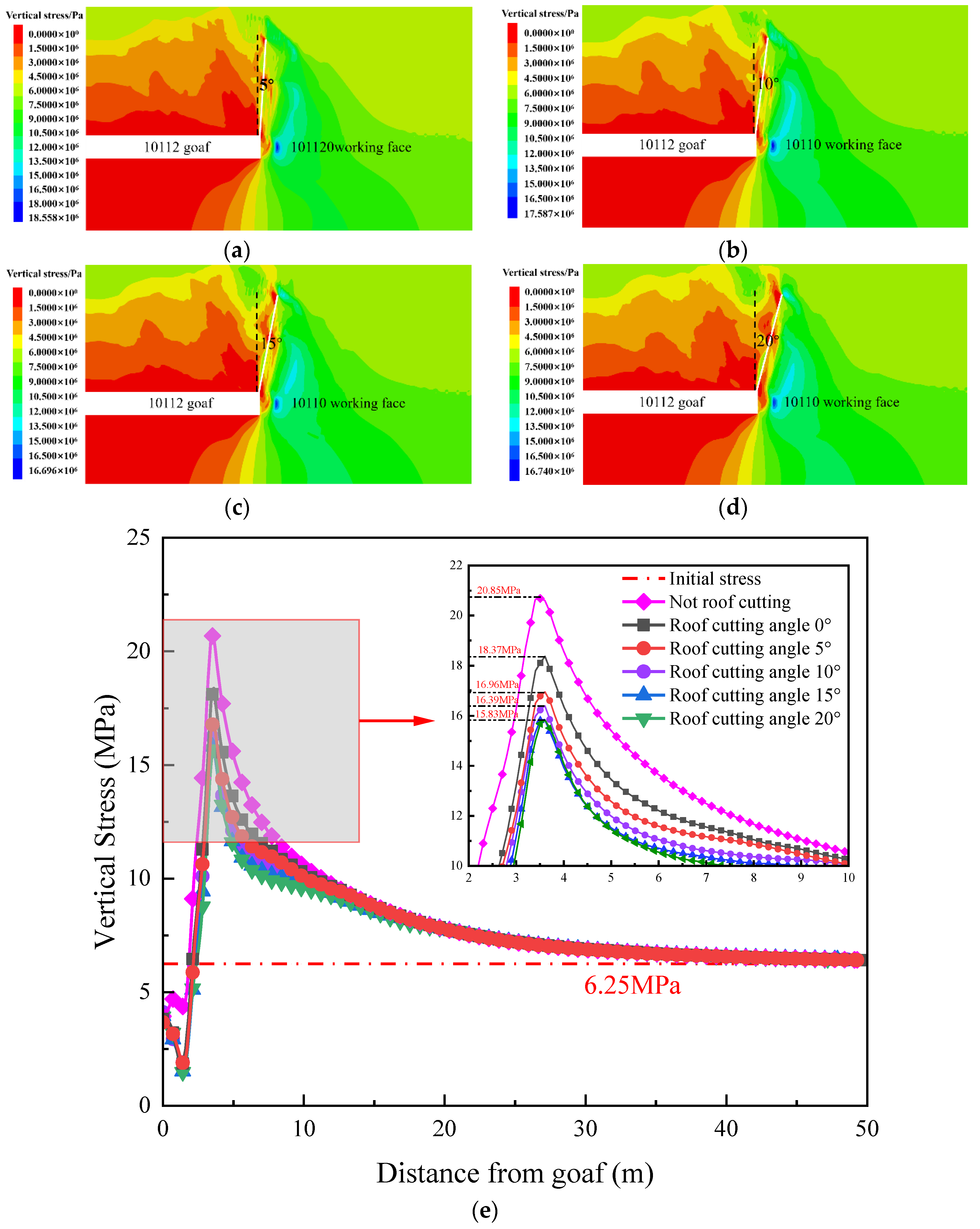
Through the above simulation analysis, the optimal roof cutting height of 21 m, but the specific angle of the roof cutting has not been determined. In the given conditions of the optimal roof cutting height, according to the goaf in different roof cutting angle conditions of the stress field change law, to obtain the optimal roof cutting angle, simulation results are shown in Figure 8 below.
It can be seen from the above stress cloud and stress distribution curve in Figure 8:
(1) When the angle of roof cutting is 0°, the peak stress along goaf is 18.37 MPa, compared to when the roof is not cut, the peak stress is reduced by 2.48 MPa, with a reduction of 11.89%; when the angle of roof cutting is 5°, the peak stress along goaf is 16.96 MPa, comparing with the roof is not cut, the peak stress is reduced by 3.89 MPa, with a reduction of 18.66%; when the roof cutting angle is 10°, the stress peak value along goaf is 16.39 MPa, comparing with the not cut, the stress peak value is reduced by 4.46 MPa, with a decrease of 21.39%; when the roof cutting angle is 15° and 20°, the trend of the stress peak value and the stress distribution curve along goaf are the same, and the stress peak value is 15.83 MPa, compared with the roof is not cut, the peak stress is reduced by 5.02 MPa, with a reduction of 24.07%;
(2) According to the trend of the stress peak value, with the increase of the roof cutting angle, the stress peak value of along goaf shows a trend of gradual decrease; there is not much difference between the stress peak value when the roof cutting angle is 15° and 20°. The roof cutting angle of 15° is the key turning point of roof cutting. This cutting angle can cut down the roof above the goaf well, and the best top cutting angle is 15°.
In summary, the reasonable parameters of roof cutting in the goaf were studied through theoretical calculation and numerical simulation, and under the premise of comprehensively considering the cost and the degree of difficulty of roof cutting, it was determined that 21 m and 15° can make the roof of above goaf completely collapse, and can effectively fill the goaf, reduce the degree of stress concentration of the coal and rock body, and provide favorable conditions of stress field for the roadway excavation along the goaf.

4.2. Numerical Simulation Analysis of Coal Pillar Width

After determining the optimal parameters of roof cutting, according to the simulation scheme of coal pillar width, analyze the stress distribution and displacement distribution of the roadway under different coal pillar widths and determine the optimal width of the coal pillar.

4.2.1. Characteristics of the Stress Distribution along the Goaf

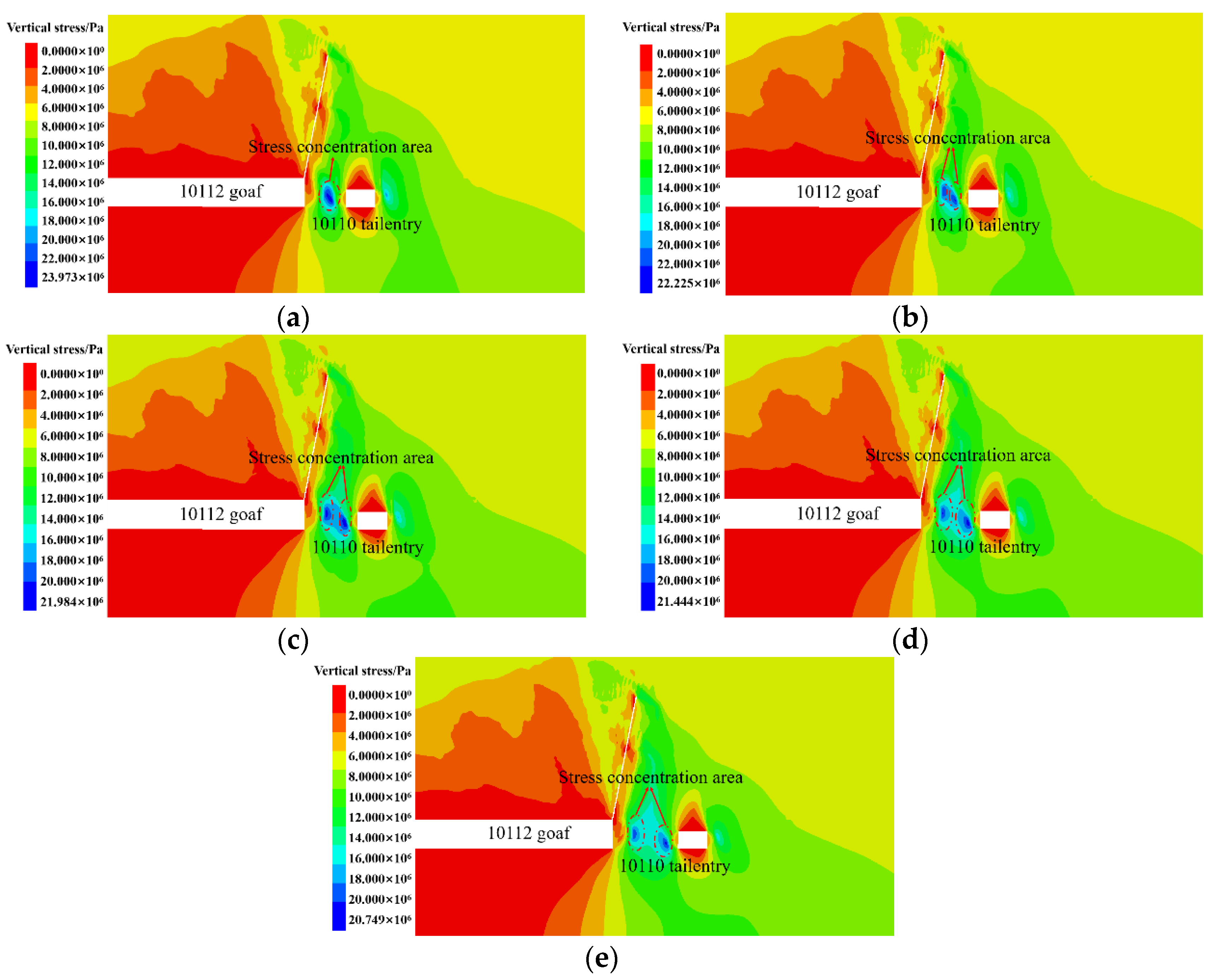
As shown in Figure 9, after the end of the upper working face mining and the balance of the roadway excavation calculation, a 50 m measuring line is arranged along the upper section along goaf to obtain the vertical stress of the roadway surrounding rock during the excavation. The peak stress is obtained by measuring the line; then, the stress concentration factor can be calculated, which is calculated as the peak stress divided by the initial stress.
Figure 9 and Table 5 can be seen:
(1) When the width of the coal pillar is 7 m, the vertical stress distribution pattern is “single hump”, and when it is 8 m and above, the vertical stress is “saddle” distribution, and it moves along the middle of the coal pillar to both sides. With the increase of the width of the coal pillar, the coal pillar gradually changed from the broken state to the supporting state of the elastic core area with a certain width;
(2) The peak vertical stress on the side of the coal pillar decreases with the increase of the width of the coal pillar left, under the width of the coal pillar of 8 m, the vertical stress peak value between the left side and the right side has an inflection point, which suggests that the width of the pillar of 8 m can effectively carry the overburden rock layer. This indicates that the width of an 8 m coal pillar can effectively carry the stress of the overlying rock layer.

4.2.2. Characteristics of the Displacement Distribution along Goaf

Through the statistical analysis of the vertical displacement and horizontal displacement data of the roadway, the maximum values of the roof subsidence and floor heave, as well as the maximum values of the coal pillar and solid coal slope moving close to the roadway were obtained, the amount of movement of the coal pillar towards the roadway is called displacement of coal pillar, and the amount of movement of the solid coal side towards the roadway is called displacement of solid coal slope, and the deformation of the roadway perimeter rock under different widths of coal pillars is shown as follows:
It can be analyzed according to the Figure 10 and Table 6:
(1) Under the condition of different coal pillar widths, the deformation of the roadway shows obvious asymmetry, in which the value of roof subsidence is much larger than the value of floor heave, and the deformation at the coal pillar is larger than that the solid coal slope; the proportion of roof subsidence in roof and floor approach under different coal pillar widths (7 m to 11 m) is 69.5%, 69.4%, 67.5%, 67.8%, and 66.9%, with the increase of coal pillar width, the proportion of roof subsidence in roof and floor approach decrease little, and the change of subsidence under each coal pillar width after 8 m is very small. The proportion of the approach of two sides under different coal pillar widths (7 m to 11 m) is 70.7%, 66.5%, 64.4%, 65.2%, and 65%, and the proportion decreases with the increase of the width of the coal pillar, which indicates that the deformation of the roadway is mainly reflected in the roof and coal pillar;
(2) An 8 m and 9 m wide coal pillar is an important turning point, compared with the displacement situation when the width of a coal pillar is 7 m and 8 m, the roof and floor of the roadway under 8 m are reduced by 26.14 mm, the two sides are reduced by 48.45 mm, and the deformation of the roadway surrounding rock and the trend of change is larger; after the coal pillar is above 9 m, the deformation of the roadway surrounding rock gradually tends to be stable and the trend of change is relatively smooth, when the width is 9 m, compared with 10 m, the roof and floor are reduced by only 7.67 mm and the two sides are reduced by 23.27 mm. It can be seen that when the width of the coal pillar is 8 m or 9 m, it is more favorable to the stability control of the roadway peripheral rock displacement.
In summary, in addition to ensuring the use of the roadway, the coal pillar needs to have a certain elastic area to facilitate the anchor solid body in the anchor cable for force. It should be avoided waste of resources caused by the width of the coal pillar. Therefore, after comprehensively analyzing the stress distribution and displacement distribution characteristics of the roadway along goaf, the width of the coal pillar is selected to be 8.0 m.

4.3. On-Site Industrial Experiments

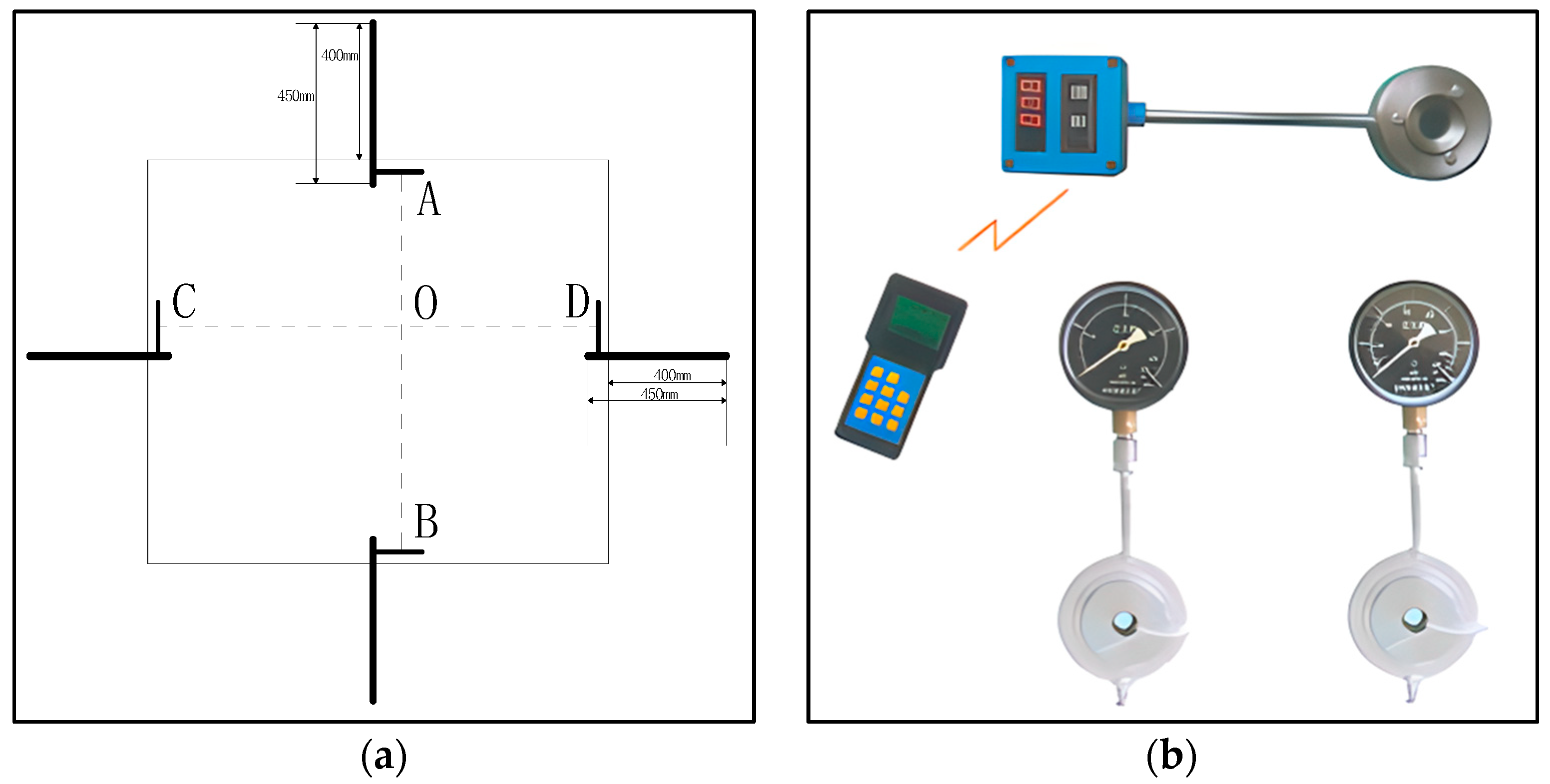
In order to observe the deformation of the roadway after retaining the 8 m coal pillar, two observation points were arranged in 10110 head entry, which are 5 m and 20 m away from the head of the excavation, respectively, and each observation point carries out the monitoring of the displacement of the roadway surface and the monitoring of the force of the bolt (anchor). The specific layout of the measurement points of the roadway is shown in Figure 11.
The displacement of the roadway surface is observed by the cross-point method, as shown in Figure 12a, and the force of the anchor (bolt) is measured by the MCS-400 force measurement gauge, as shown in Figure 12b; both require human recording and reading of data. The frequency of observation is once a day in the section within 50 m from the head-on or in front of the working face and 2–3 times a week in the other ranges.

4.3.1. Roadway Surface Displacement Observation Result

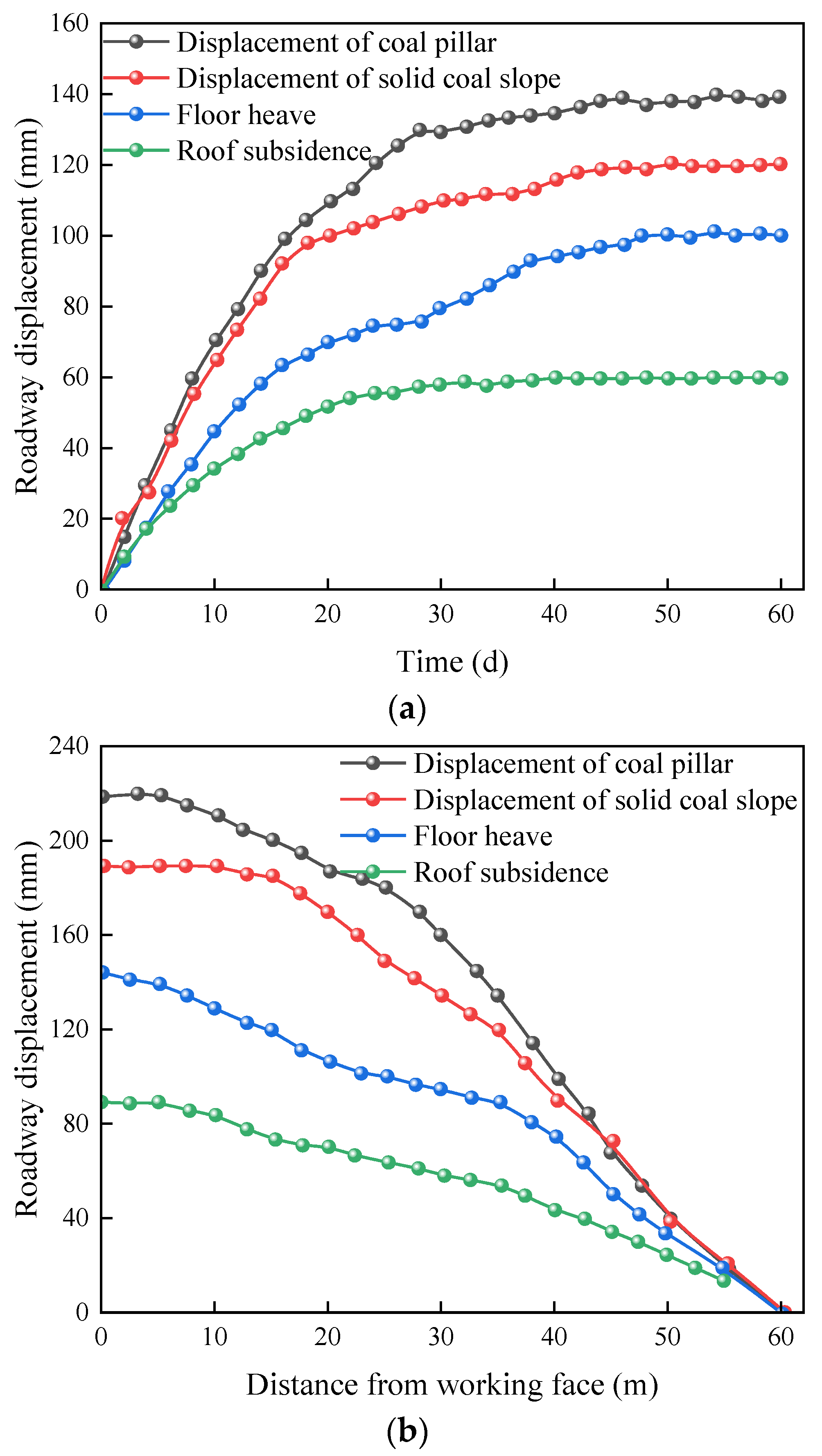
The observed displacement results of the roadway surface at measurement points 1 and 2 during excavation and working face mining are as follows in Figure 13. The surface displacement observation of the roadway section can be used to verify the reasonableness of the width of the coal pillar and can also be used as a feedback study based on the displacement observation results.
As can be seen from Figure 13,
(1) According to the curve from the observation results of measurement point 1 during the roadway excavation, it can be seen that during the early stage of the roadway excavation (20d), the curve is inclined to a larger extent, which indicates that the roadway deformation rate is faster; during the excavation period from 20d to 30d, the slope of the curve decreases significantly, which indicates that the deformation of the surrounding rock tends to be flat; after the roadway excavation period of 40d, the curve tends to be flat, and the deformation of the surrounding rock is maintained unchanged; During the tunneling process, the maximum displacements of the coal pillar, solid coal slope, roof subsidence, and floor heave are 140 mm, 120 mm, 60 mm, and 100 mm respectively; the lateral support stress in the mining area causes the displacement of the coal pillar to be larger than the solid coal slope;
(2) According to the curve from the displacement observation results during the working face mining at measuring point 2. It can be seen that, due to the influence of mining stress, during the mining back, with the increase of the mining distance, the surface displacement of measuring point 2 increases; the maximum displacement of the coal pillar, solid coal slope, roof subsidence and floor heave increases to 220 m, 190 mm, 90 mm, and 145 mm.
To summarize, according to the observation results of the roadway surface displacement at measurement points 1 and 2, it can be seen that the deformation of the roadway surrounding rock has been better controlled under the effect of leaving a certain width of small coal pillars and proper support.

4.3.2. Anchor (Bolt) Stress Monitoring Result

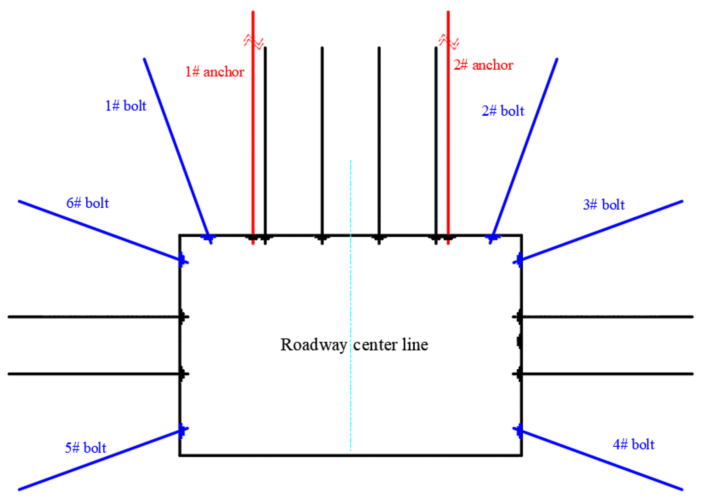
In the process of roadway excavation, in order to ensure the safety of roadway construction, a number of anchors and bolts are selected at the location of the observation station to monitor the force; the anchor and bolt numbers are as follows in Figure 14. By reading and recording the data and then analyzing them statistically, the force on the anchor and bolt during the excavation period can be obtained.
It can be seen from Figure 15 that
(1) According to the monitoring data, the average bolt force of 1#~6# bolts are 136.77 KN, 148.91 KN, 121.85 KN, 121.53 KN, 114.34 KN, and 108.87 KN, and with the increase of tunneling distance, the force distribution of each bolt is between 100~140 KN, which is in the normal range of bolt force. This shows that the bolts play a good role in controlling the surrounding rock;
(2) Through the observation and analysis of anchor stress, it can be seen that the stress borne by #1 is larger than that of #2 because #1 is closer to the coal pillar, and the stress borne by it is larger than that of #2; the stress of the anchor cable changed greatly when the tunneling distance was below 40 m, but the stress of the anchor became smoother after the roadway was tunnel for 40 m, and the average stress of the #1 anchor cable was 199.34 KN, and that of the #2 anchor cable was 188.91 KN, indicating that the high prestressing anchor could support the roof strata well, and the difference of initial prestressing was not much.
To summarize, the mine pressure monitoring was carried out on the 10110 head entry, and according to the observation, it was found that under the condition of leaving 8 m small coal pillars and proper support, the surrounding rock of the roadway was within a reasonable interval, and the anchor and bolt were in good condition and could improve the strength of the surrounding rock, which indicated that leaving 8 m small coal pillars along the goaf roadway was a success.

5. Conclusions

(1) Cutting roof pressure relief can effectively control the stability of coal pillar; through theoretical calculation, we obtained the theoretical parameters of roof cutting pressure relief in the goaf: the height is 18 m, the angle should be less than or equal to 21°, and then used numerical simulation to analyze the stress distribution along goaf under different heights and angles, and the comparative analysis resulted in the optimal height and angle are 21 m and 15°;
(2) According to the theory of ultimate strength of coal pillar and the theory of calculation of coal pillar load, the theoretical width range of coal pillar retention is 7.58~11.7 m. To obtain the coal pillar retention width, the stress distribution law of the coal body and the displacement distribution of the roadway under different widths were studied, and the reasonable coal pillar width was determined to be 8 m;
(3) The results of on-site industrial experiments show that the roadway surrounding rock deformation is between 60~220 mm, which is within a reasonable range; the bolt force is between 100~140 kN, and the average value of anchor force is 199.34 kN and 188.91 kN, which are all in a working condition; the support has played its role very well, and controlled the deformation of the roadway surrounding rock, which indicates that the construction of 8 m small coal pillars along goaf is successful;
(4) The research results have certain limitations and can only provide guidance for Jinniu Coal Mine; in the course of the subsequent research, it is necessary to analyze the mechanism role of the surrounding rock deformation under thick hard roof driving along goaf and to further explore the idea of controlling surrounding rock deformation.

Author Contributions

Conceptualization, W.G.; methodology, W.G.; software, D.X; validation, D.X.; formal analysis, D.X.; investigation, D.X.; resources, W.G.; data curation, H.Z.; writing—original draft preparation, Z.H.; writing—review and editing, W.G.; visualization, D.X.; supervision, W.G.; project administration, W.G.; funding acquisition, W.G. All authors have read and agreed to the published version of the manuscript.

Funding

This research was funded by the National Natural Science Foundation of China, grant number 52274103.

Institutional Review Board Statement

Not applicable.

Informed Consent Statement

Not applicable.

Data Availability Statement

The raw data supporting the conclusions of this article will be made available by the authors upon request.

Conflicts of Interest

The authors declare no conflicts of interest.

References

  1. Guo, W.; Deng, K.; Zou, Y. Research status and main issues of strip mining in China. Coal Sci. Technol. 2004, 32, 7–11. [Google Scholar]
  2. Cong, L.; Weng, M.; Qin, Z.; Feng, M. Instability mechanism and prevention of wide coal pillar with three strong stress disturbances under hard roof. J. China Coal Soc. 2022, 47, 125–134. [Google Scholar]
  3. Hao, R. Determination of reasonable size of coal pillar in longwall face. Shanxi Coking Coal Sci. Technol. 2012, 36, 20–22+29. [Google Scholar]
  4. Huang, Q.; Qian, M.; Shi, P. Structural analysis of cyclic pressurization of old roofs in shallow buried coal seams. J. China Coal Soc. 1999, 581–585. [Google Scholar]
  5. Dong, S.; Li, W. Influence analysis of principal stress deflection on fault stability based on theory of internal and external stress fields. Saf. Coal Mines 2021, 52, 213–219. [Google Scholar]
  6. Song, Z.; Hao, J.; Shi, Y.; Tang, J.; Liu, J. An overview of connotation and development of practical ground pressure control theory. J. Shandong Univ. Sci. Technol. (Nat. Sci.) 2019, 38, 1–15. [Google Scholar]
  7. Jia, X.; Zhai, Y. A review of the theory and practice of thin-sheet mine pressure in quarries. Mine Press. Roof Manag. 1999, 22–25, 238. [Google Scholar]
  8. Jia, X.; Li, H.; Wang, Q.; Jia, R. Application of thin-slab mining pressure theory to roof coal workings. J. Taiyuan Univ. Technol. 1999, 30, 179–183. [Google Scholar]
  9. Ma, R. Research on Reasonable Narrow Width of Coal Pillar for Decompression and Anticlimbing along the Hollow Tunnel. Master’s Thesis, Guizhou University, Guiyang, China, 2021. [Google Scholar]
  10. Zhan, Z. Study on Reasonable Reserved Coal Pillar Width for Gob Side Entry Driving by Roof Cutting and Pressure Relief in Selian No.2 Mine. Master’s Thesis, Anhui University of Technology, Ma’anshan City, China, 2021. [Google Scholar]
  11. Bo, J.; Wang, W.; Hou, C.; Huang, H. Research on the control mechanism and support technology of the perimeter rock in the open-cut tunnel. J. China Coal Soc. 2000, 478–481. [Google Scholar] [CrossRef]
  12. Xu, L.; Li, M.W.; Guo, L.; Xiao, T.Q.; Liu, H.L.; Elmo, D. Critical parameters and engineering applications of cut-through critical layer depressurization along a hollow tunnel. J. Min. Saf. Eng. 2023, 40, 91–100. [Google Scholar]
  13. Yang, Z.; Liu, C.; Tang, S.; Dou, L.; Cao, J. Rock burst mechanism analysis in an advanced segment of gob-side entry under different dip angles of the seam and prevention technology. Int. J. Min. Sci. Technol. 2018, 28, 891–899. [Google Scholar] [CrossRef]
  14. Zha, W.; Shi, H.; Liu, S.; Kang, C. Surrounding rock control of gob-side entry driving with narrow coal pillar and roadway side sealing technology in Yangliu Coal Mine. Int. J. Min. Sci. Technol. 2017, 27, 819–823. [Google Scholar] [CrossRef]
  15. Xu, C.; Yuan, L.; Cheng, Y.; Wang, K.; Zhou, A.; Shu, L. Square-form structure failure model of mining-affected hard rock strata: Theoretical derivation, application and verification. Environ. Earth Sci. 2016, 75, 1180. [Google Scholar] [CrossRef]
  16. Chen, B.; Liu, C.; Wang, B. A case study of the periodic fracture control of a thick-hard roof based on deep-hole pre-splitting blasting. Energy Explor. Exploit. 2022, 40, 279–301. [Google Scholar] [CrossRef]
  17. Zhao, T.; Liu, C.; Yetilmezsoy, K.; Zhang, B.; Zhang, S. Fractural structure of thick hard roof stratum using long beam theory and numerical modeling. Environ. Earth Sci. 2017, 76, 751. [Google Scholar] [CrossRef]
  18. Bu, Q.; Tu, M.; Zhang, X.; Zhang, M.; Zhao, Q. Analysis of Energy Accumulation and Dispersion Evolution of a Thick Hard Roof and Dynamic Load Response of the Hydraulic Support in a Large Space Stope. Front. Earth Sci. 2022, 10, 884361. [Google Scholar] [CrossRef]
  19. Li, J.; Fu, B.; Zhang, H.; Zhao, Q.; Bu, Q. Study on Fracture Behavior of Directly Covered Thick Hard Roof Based on Bearing Capacity of Supports. Appl. Sci. 2023, 13, 2546. [Google Scholar] [CrossRef]
  20. Yu, M.; Zuo, J.; Sun, Y.; Mi, C.; Li, Z. Investigation on fracture models and ground pressure distribution of thick hard rock strata including weak interlayer. Int. J. Min. Sci. Technol. 2022, 32, 137–153. [Google Scholar] [CrossRef]
  21. Guo, Y.; Lu, C.; He, Z.; Song, J. Numerical and Field Investigations of Tremors Induced by Thick-Hard Strata Fracture. Appl. Sci. 2022, 12, 11151. [Google Scholar] [CrossRef]
  22. Ju, F.; Xiao, M.; He, Z.; Ning, P.; Huang, P. Study on Fracture and Stress Evolution Characteristics of Ultra-Thick Hard Sandstone Roof in the Fully Mechanized Mining Face with Large Mining Height: A Case Study of Xiaojihan Coal Mine in Western China. Adv. Civ. Eng. 2018, 2018, 1–12. [Google Scholar] [CrossRef]
  23. Huo, B.; Meng, F.; Li, T.; Song, Z.; Jin, J.; Huang, Y. Research on small coal pillar protection technology for consolidation face of multi-layer hard roof and extra thick coal seam. Coal Sci. Technol. 2024, 52, 13–23. [Google Scholar] [CrossRef]
  24. Qin, D.; Chang, Z.; Xia, Z. Experiment Study on the Mechanical Behavior and Acoustic Emission Response of Thick and Hard Sandstone Roof in Xinjiang Mining Area. Adv. Civ. Eng. 2024, 2024, 1–12. [Google Scholar] [CrossRef]
  25. Hu, B.; Wu, Y.; Yu, Y.; Xie, P.; Wen, H.; Zhang, H. Numerical study on the dynamic pressure control for self-forming roadways using CHRCT in thin coal seams with thick and hard roofs. Energy Explor. Exploit. 2024. [Google Scholar] [CrossRef]
  26. Li, C.; Xin, D.; Liu, Y.; Chen, T. A Case Study on Strong Strata Behaviors Mechanism of Mining Reserved Roadway and Its Prevention Techniques. Processes 2023, 11, 1341. [Google Scholar] [CrossRef]
  27. Zhu, J.; Li, W.; Teng, B.; Liu, Y. Failure characteristics of thick hard roof stratum under hydraulic pre-splitting and its application in a coal mine, Dongsheng mining area. Environ. Earth Sci. 2024, 83, 153. [Google Scholar] [CrossRef]
  28. Li, Z.; Qi, C.; Gao, R.; Yu, B.; Zhu, Y.; Zhang, H.; Zhang, J. Simulation Study and Engineering Application of Weakening Mine Pressure Behavior in Stope through Ground Fracturing Thick and Hard Rock Strata. Appl. Sci. 2024, 14, 415. [Google Scholar] [CrossRef]
  29. Wang, M.; Xu, Y.; Xu, Q.; Shan, C.; Li, Z.; Nan, H.; Li, Y.; Liu, H.; Chu, T. Stability control of overburden and coal pillars in the gob-side entry under dynamic pressure. Int. J. Rock Mech. Min. 2023, 170, 105490. [Google Scholar] [CrossRef]
  30. Zhao, J. A study on reasonable width of coal pillar for protecting the roadway along the hollow digging roadway in the working face with hard roof island. Coal Technol. 2022, 41, 71–75. [Google Scholar]
  31. Shan, C.; Qi, S.; Xie, G.; Qin, J.; Li, Y.; Huang, P.; Zhang, Q.; Ren, G. Study on Multi-scale strength and Control of Coal Pillar in Gob Side Entry of Fully Mechanized Top Coal Caving Face in “Double Hard’ Seam. Coal Technol. 2023, 42, 63–68. [Google Scholar]
  32. Hou, C.; Li, X. Stability principles of large and small structures in the perimeter rock of a generalized open cut. J. China Coal Soc. 2001, 1–7. [Google Scholar]
  33. Feng, Z. Review of the “Control of Surrounding Rock in Chinese Coal Mining Quarries”. Mine Pressure and Roof Management. 1995. [Google Scholar]
  34. Hou, C.; Ma, N. Discussion on the stress and limit equilibrium zones of coal body in two gangs of coal seam roadway. J. China Coal Soc. 1989, 4, 21–29. [Google Scholar]
  35. Kumar, A.; Kumar, R.; Singh, A.K.; Ram, S.; Singh, P.K.; Singh, R. Numerical modelling-based pillar strength estimation for an increased height of extraction. Arab. J. Geosci. 2017, 10, 411. [Google Scholar] [CrossRef]
  36. Holland, C.T. The Strength of Coal in Mine Pillars. In Proceedings of the 6th U.S Symposium on Rock Mechanics (USRMS), Rolla, MI, USA, 28–30 October 1964. ARMA-64-450. [Google Scholar]
  37. Salamon, A.; Munro, M. A study of the strength of coal pillars. J. S. Afr. Inst. Min. Metall. 1967, 68, 55–67. [Google Scholar]
  38. Bieniawski, Z.T. The point-load test in geotechnical practice. Eng. Geol. 1975, 9, 1–11. [Google Scholar] [CrossRef]
  39. Wang, P.; Zhao, J.; Wang, C.; Sun, C.; Xu, C.; Song, Z.; Su, Y. Mechanism of gob-pillar interaction for subcritical panels and its application. Chin. J. Rock. Mech. Eng. 2017, 36, 1185–1200. [Google Scholar]
  40. Cheng, H.; Lu, D.; Wang, E. Theoretical analysis and calculate on the thickness of the medium thickness seam nether roof. Hebei Coal 2011, 16–17. [Google Scholar] [CrossRef]
  41. Fu, F. Research on the technology of cutting top and unloading pressure of small coal pillar in medium-thickness coal seam. Shanxi Chem. Ind. 2023, 43, 141–143. [Google Scholar]
  42. Gaddy, F.L. A Study of the Ultimate Strength of Coal as Related to the Absolute Size of the Cubical Specimens Tested; Virginia Polytechnic Institute: Blacksburg, VA, USA, 1956. [Google Scholar]
  43. Zhang, Y. Research and Application of Reserved Narrow Coal Pillar Roof Cutting and Pressure Relief. Technol. Qingyun Coal Ind. Shandong Coal Sci. Technol. 2023, 41, 27–31. [Google Scholar]
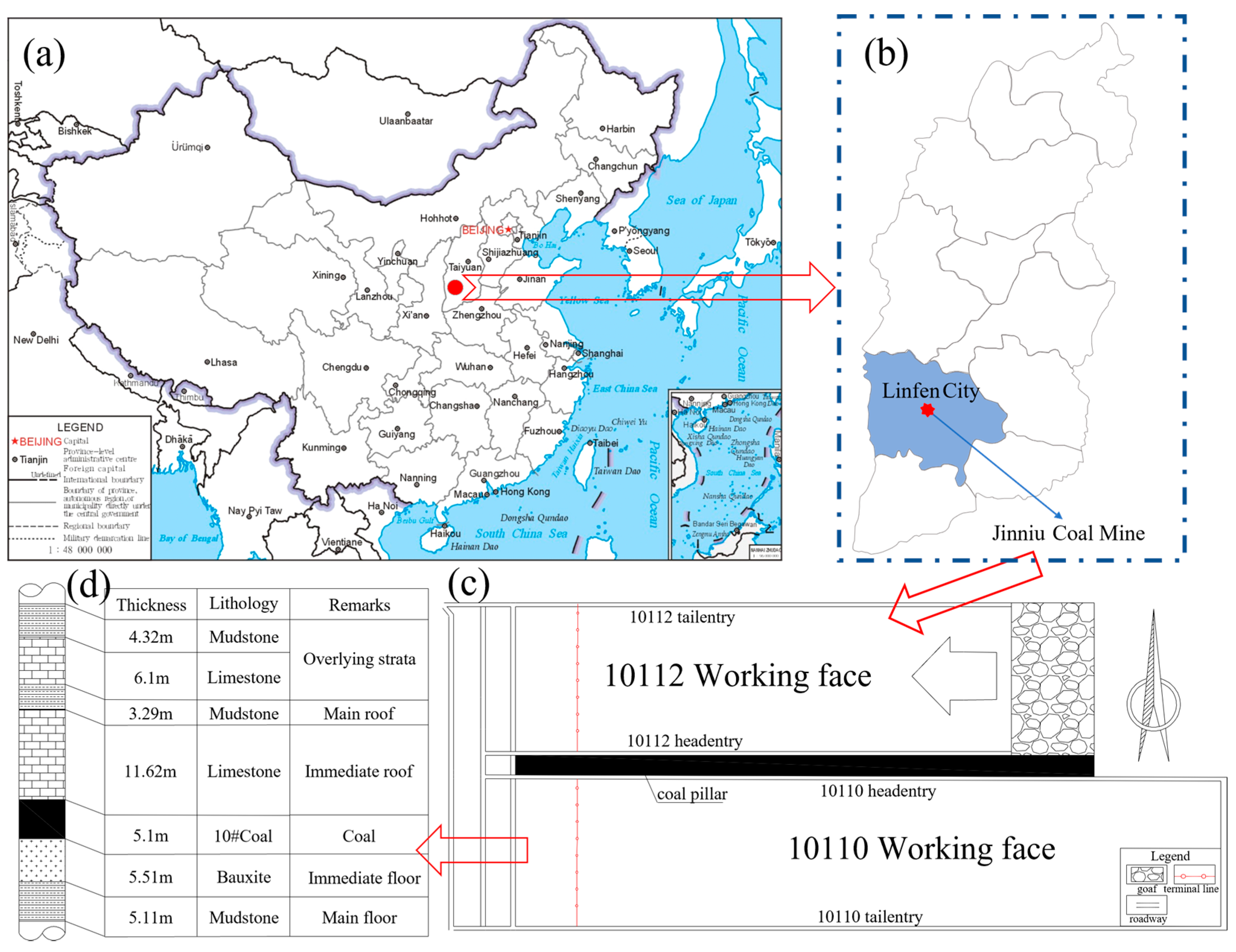
Figure 1. Mine location and working face layout. (a) Location of Jinniu Coal Mine in China; (b) Location of Jinniu Coal Mine in Linfen City; (c) the working face layout; (d) the histogram of the working face.
Applsci 14 06381 g001
Figure 2. Structural model of the overburden rock strata before and after roof cutting. (a) before roof cutting. (b) after roof cutting.
Applsci 14 06381 g002
Figure 3. Coal pillar bearing structure in goaf excavation.
Applsci 14 06381 g003
Figure 4. Flac3D numerical calculation model and its boundary diagram.
Applsci 14 06381 g004
Figure 5. Schematic diagrams of different roof-cutting parameters. (a) Simulation parameters for roof cutting height; (b) simulation parameters for roof cutting angle.
Applsci 14 06381 g005
Figure 6. Stress distribution along goaf under different roof cutting heights. (a) Not roof cutting. (b) Roof cutting height 18 m. (c) Roof cutting height 21 m. (d) Roof cutting height 24 m.
Applsci 14 06381 g006
Figure 7. Stress distribution curve along goaf under different roof cutting heights.
Applsci 14 06381 g007
Figure 8. Stress distribution and curve along goaf under different roof cutting angles. (a) Roof cutting angle 5°. (b) Roof cutting angle 10°. (c) Roof cutting angle 15°. (d) Roof cutting angle 20°. (e) Stress distribution curve along goaf under different roof cutting angles.
Applsci 14 06381 g008
Figure 9. Vertical stress distribution of the roadway under different widths of coal pillars during excavation. (a) Width of coal pillar 7 m. (b) Width of coal pillar 8 m. (c) Width of coal pillar 9 m. (d) Width of coal pillar 10 m. (e) Width of coal pillar 11 m.
Applsci 14 06381 g009
Figure 10. Deformation of roadway under different widths of coal pillars.
Applsci 14 06381 g010
Figure 11. Schematic diagram of mining roadway station layout.
Applsci 14 06381 g011
Figure 12. Observation methods and equipment. (a) Cross-point method. (b) MCS-400 force measurement gauge.
Applsci 14 06381 g012
Figure 13. Surface displacement observations of measuring points during excavation and working face mining. (a) Observations on the displacement of the roadway at point 1 (during excavation); (b) observations of the displacement of the roadway at point 2 (during the mining of the working face).
Applsci 14 06381 g013
Figure 14. Anchor (bolt) monitoring map.
Applsci 14 06381 g014
Figure 15. Anchor and cable force monitoring results during roadway excavation. (a) Results of bolt stress monitoring. (b) Results of anchor stress monitoring.
Applsci 14 06381 g015
Table 1. Table of values of height coefficients for collapse zones.
Immediate Roof LithologyCompressive Strength/MPa c 1 c 2
hard>402.116
medium hard20–404.719
weak<206.232
Table 2. Formulas and parameters for calculating the height of the fracture zone.
Rock Quality of the Roof of the Working FaceFracture Zone Height H/mLateral Support Angle θ  (°)
stiff H = 100 h 1.2 h + 2 ± 8.9 30
medium-hard H = 100 h 1.6 h + 3.6 ± 5.6 20
flabby H = 100 h 3.1 h + 5 ± 4 10
Table 3. Numerical simulation model parameters.
LayerModulus of Elasticity E/GPaPoisson’s RatioInternal Friction Angle fCohesion C/MPaTensile Strength t/MPa
mudstone1.770.225.36.30.58
limestone6.50.3225.311.25.7
coal6.40.3122.82.70.49
bauxite14.20.2325.36.32.53
siltstone3.340.23423.21.29
Table 4. Coal pillar width simulation program.
Program12345
Width of coal pillar/m7891011
Table 5. Peak vertical stress and stress concentration factor for different coal pillar widths.
Width of Coal Pillar/mPeak Vertical Stress/MPaStress Concentration Factor
Coal PillarSolid Coal SlopeCoal PillarSolid Coal Slope
723.0418.743.693.00
820.0517.143.212.74
919.9816.103.202.58
1019.3416.073.092.57
1119.2015.653.072.50
Table 6. Deformation of roadway under different widths of coal pillars.
Width of Coal Pillar/mRoof Subsidence/mmFloor Heave/mmRoof and Floor Approach/mmCoal Pillar/mmSolid Coal Slope/mmApproach of Two Sides/mm
7159.9470.30230.24165.6368.55234.18
8141.6062.50204.10123.4362.30185.73
9120.0057.90177.90103.4657.28160.74
10114.4754.77170.2389.5547.82137.47
11106.9352.68159.6180.9943.66124.65
Disclaimer/Publisher’s Note: The statements, opinions and data contained in all publications are solely those of the individual author(s) and contributor(s) and not of MDPI and/or the editor(s). MDPI and/or the editor(s) disclaim responsibility for any injury to people or property resulting from any ideas, methods, instructions or products referred to in the content.