Article

Effects of Materials and Riblets on Erosion Mitigation Induced by Multiple Collapses of Cavitation Bubbles

1
Institute of Ship Technology, Ocean Engineering and Transport Systems, University of Duisburg-Essen, 47057 Duisburg, Germany
2
Department of Physics and Energy Engineering, Amirkabir University of Technology, Tehran 159163-4311, Iran
3
Laserinstitut Hochschule Mittweida, University of Applied Sciences Mittweida, Technikumplatz 17, 09648 Mittweida, Germany
*
Author to whom correspondence should be addressed.
Appl. Sci. 2024, 14(15), 6452; https://doi.org/10.3390/app14156452
Submission received: 14 June 2024 / Revised: 20 July 2024 / Accepted: 21 July 2024 / Published: 24 July 2024
(This article belongs to the Special Issue Advances in Active and Passive Techniques for Fluid Flow Manipulation)

Abstract

:
The current research investigates the effects of materials and riblets on cavitation-induced erosion morphology, depth, and cross-sectional area through experimental approaches. To achieve these aims, the erosion of pure aluminum (1xxxAl or Al) and alpha brass (CuZn37 or CZ108), in the presence and absence of bio-inspired sawtooth riblets, was examined after exposure to multiple collapses of single cavitation bubbles with a wall distance of 1.8 (dimensionless). The results indicate that the erosion morphology resembles a rounded cone with a circular cross-section. Brass provides 21.6% more erosion resistance compared to that of Al in terms of material properties. Furthermore, the erosion for both Al (depth by 3.8% and width by 18.3%) and brass (depth by 7.9% and width by 27.4%) decreases in the presence of riblets compared to the results for flat surfaces. The greater erosion resistance of brass compared to Al is attributed to the superior mechanical stability of brass, making it a potentially suitable alloy for use in propellers and hulls in the shipping industry. In summary, the results reveal that riblet-equipped materials with high mechanical durability are promising erosion-resistant materials for the shipping industry. However, the potential for chemical reactions in a cathodic environment should be addressed to provide a comprehensive perspective in regards to reducing corrosion intensity.

1. Introduction

Cavitation is a phenomenon that usually occurs in ship and hydraulic machinery systems, in biochemical and biomedical and ultrasonic systems, and in various valves and injector nozzles, etc. Cavitation may cause mass loss, and it may damage the surface of immersed bodies of systems where cavitating flows or cavitation bubbles are generated. This cavitation-induced damage reduces the performance of such system [1,2,3,4,5,6,7]. The cavitation-induced damage is caused by the collapse of many tiny bubbles near a boundary. These tiny bubbles are usually of mesoscale, microscale, and nanoscale sizes. Previous research dealt mostly with the dynamics of a single cavitation bubble of mesoscale or microscale sizes near a boundary.
Previous research numerically and experimentally studied the single cavitation bubble and its destructive effects near a solid boundary, such as erosion on its surface [8,9,10,11,12]. The outcomes of these studies demonstrated that a microjet forms during the collapse process of the single cavitation bubble near a solid surface. This microjet, impacting on the solid boundary, induces surface erosion after several successive bubble collapses. Furthermore, a toroidal cavity structure forms after the first collapse, inducing more damage on the solid boundary. This toroidal cavity consists of several tiny bubbles that cause erosion after collapsing. Moreover, investigation of the generation of acoustic transient laser-induced cavitation bubbles near solid boundaries revealed that a significant pressure impact is generated inside a single cavitation bubble during its first collapse [13]. The impact on the solid surface reaches pressures up to 60 × 103 pascal (Pa). This indicated that a major portion of the bubble collapse energy is converted to acoustic energy.
Experimental studies on laser-induced cavitation bubbles collapsing near solid surfaces reveal that the collapse dynamics and direction of the bubble are influenced by the curvature of the solid surface and thermodynamic effects [14,15,16,17,18]. Additionally, the formation of counter jets and micro jets during the rebound process occurs at specific stand-off distances between the bubble center and the solid boundary due to the pressure gradient around the single cavitation bubble. The morphology of the solid surface can also alter the momentum of the microjet formed during the bubble collapse process. In summary, these studies emphasize that if surfaces are provided with micro structured riblets, the cavitation-induced erosion from bubbles collapsing on solid boundaries can be mitigated.
Computational molecular dynamics (MD) simulations of the collapse dynamics of nanobubbles and their induced damage on solid boundaries provide valuable insights at the atomic and molecular scale regarding the mechanisms of collapse, erosion, and corrosion induced by cavitation [19,20,21,22,23,24,25,26,27,28]. The results revealed several key findings: the temperature of the nano jet rises sharply as the nanobubble shrinks after uniform compression [19,20]; the collapse time of the nanobubble is approximately in the picosecond range [21,22]; erosion on the solid surface is induced by the impact of nano jet molecules [23,24]; the induced shock wave cannot create holes or cavities in the absence of nanobubbles [25,26,27]; chemical reactions are accelerated during corrosion [21]; surface morphology significantly affects the momentum of the nano jet [28]; and nano riblets decrease the erosion induced by nano jets [29].
The literature review reveals that both experimental and computational results indicate that bubble collapse decreases bubble volume and forms a water jet that moves toward the solid surface. As a result of the impact between the water jet and the solid, the momentum of the water jet transfers to the solid, leading to erosion and corrosion. These undesirable outcomes, which reduce the lifetime of marine components, can be mitigated by riblets. However, the way in which materials provided with riblets perform remains unclear. Specifically, the effects of material surfaces provided with riblets on cavitation-induced erosion have not been fully addressed. These unclear issues result in a lack of data that could aid in selecting materials for erosion resistance applications in different environmental conditions. Furthermore, since the behavior of surfaces with and without riblets under similar conditions is not fully understood, the manner in which riblet surfaces act as anti-erosion agents and to what degree they reduce erosion compared to surfaces without riblets remains unclear.
This study was conducted to uncover the behavior of materials and surfaces with and without riblets under similar conditions. In details, the current study investigates the effects of pure aluminum (1xxxAl or 99%Al or Al) and alpha brass (CuZn37 or CZ108), both with and without bio-inspired sawtooth riblets, on cavitation-induced erosion morphology, depth, and cross-sectional area through experimental approaches. The results obtained from the flat surfaces of Al and brass under similar cavitation conditions effectively reveal the effects of material properties on erosion resistance. Additionally, when these materials are provided with riblets, the effects of riblets on reducing erosion can be observed, demonstrating the performance of riblets as a passive anti-erosion strategy.

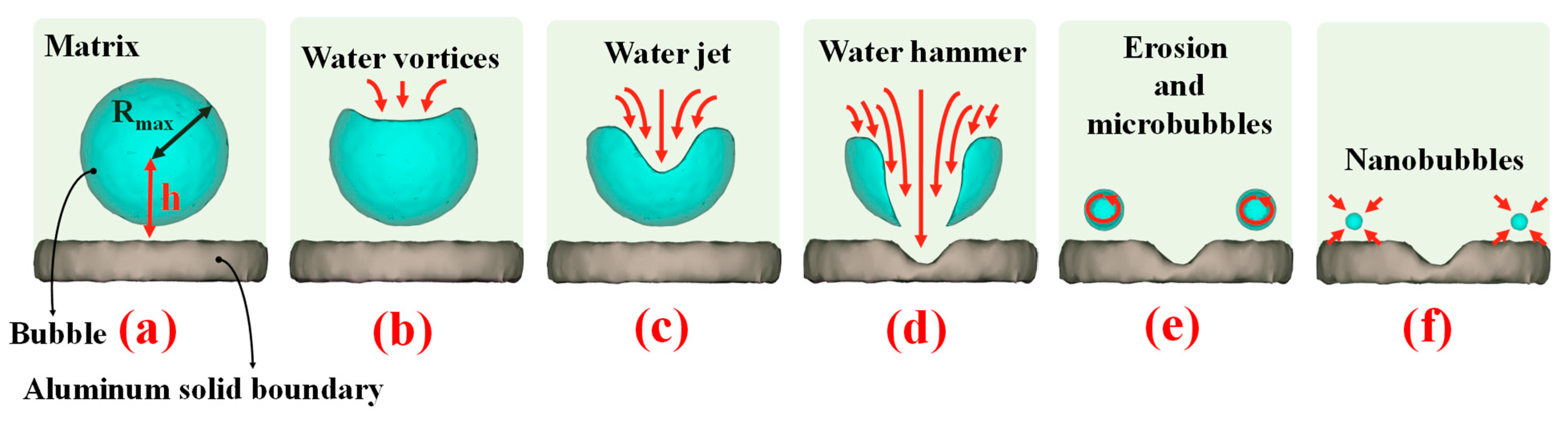
2. Background: Single Cavitation Bubble Near Solid Boundary

Formation of a bubble near the surface and its subsequent collapse can lead to erosion on the solid surface. To provide further insight into this phenomenon, Figure 1 illustrates the collapse of a bubble near the solid boundary surface, along with an image of the solid boundary before, during, and after erosion. When a complete bubble, with its maximum radius (Rmax), forms near the flat rigid surface of the solid boundary (Figure 1a), the interaction between the boundary and the bubble’s wall initiates the collapse process. At the onset of the collapse process, water vortices form and contribute to the shrinking and crumbling of the upper wall of the bubble (Figure 1b). As time elapses, additional flow of water vortices are drawn into thevortices, contributing to the formation of a water jet (Figure 1c). The establishment of the water jet results in a reduction in the volume of the bubble.
As the water jet progresses forward, additional water vortices, formed due to the crumbling of the bubble wall, join the water jet and further reduce the remaining volume of the bubble. At this juncture, the water jet transforms into a water hammer and strikes the flat surface, resulting in surface erosion and the formation of a semi-spherical pit (Figure 1d). After erosion, the remaining water vortices form microbubbles (Figure 1e). Over time, the volume of the microbubbles diminishes as a result of their rotation and interactions between the molecules on the microbubble wall and the molecules in the surrounding matrix. These processes decrease the radius of the microbubble, eventually generating nanobubbles (Figure 1f). Generally, nanobubbles persist within the matrix, and are capable of migrating freely. Upon collision with the flat surface, they contribute to nano-erosion.
In the case of riblets, different scenarios unfold. Riblets influence the flow of water vortices and consequently, the formation of the water jet and hammer. When the bubble collapses near a surface with riblets, the water vortices are diverted and separated. Consequently, the convergence of water vortices weakens, and they fail to merge into a cohesive water jet. Under these conditions, the resulting water jet is less powerful and lighter, leading to a weaker impact on the surface. Therefore, it can be inferred that erosion near surfaces with riblets may be reduced compared to that near flat surfaces. In this regard, an experimental approach is employed herein to elucidate the effects of riblets on induced erosion during bubble collapse.
In the case of erosion, it can expressed that, the cavitational destruction process of erosion [22,30,31] starts with plastic strain effects on the surface of the slab. At this stage, nano-cracks appear and gradually grow into micro-cracks [22]. During this process, the rate of material loss is very low. However, with repeated bubble collapse near the surface at a constant location, the micro-cracks grow and lead to the formation of pits on the surface. At this stage, the rate of material loss rises, and the depth of the pits increases. Eventually, the rate of material loss decreases, as internal stresses has not yet accumulated.
In addition to cavitational erosion, parallel material loss and chemical reactions [21,31] can occur, accelerating erosion and pit growth. In parallel material loss, typically called wear, materials in the erosion region are lost due to the parallel mechanical interaction between the slabs and the fluid flow. In corrosion (chemical reaction), the fresh surface of the slab undergoes chemical reactions with the liquid, forming new materials, while simultaneously pushing down the surface of the slabs. The products of the reaction accumulate inside and around the pits. However, the rate of chemical reaction depends on the cathodic environment and time.
Among these types of erosion, cavitational erosion and chemical reactions are the most probable erosion mechanisms in the current research. Material loss due to parallel mechanical interaction requires significant parallel mechanical interaction between slabs and liquids, whereas the impulse direction of the water hammer is perpendicular to the surface of the slabs. Consequently, the current research focuses on erosion resulting from cavitational erosion and chemical reactions. In this paper, the chemical components produced during chemical reactions are only discussed in Section 5.3. The rapid collapse of bubbles, the short interaction time between the fresh surface of the slab and water, and the lack of a cathodic environment result in a lower rate of chemical reaction compared to that of cavitational erosion.

3. Experimental Setup

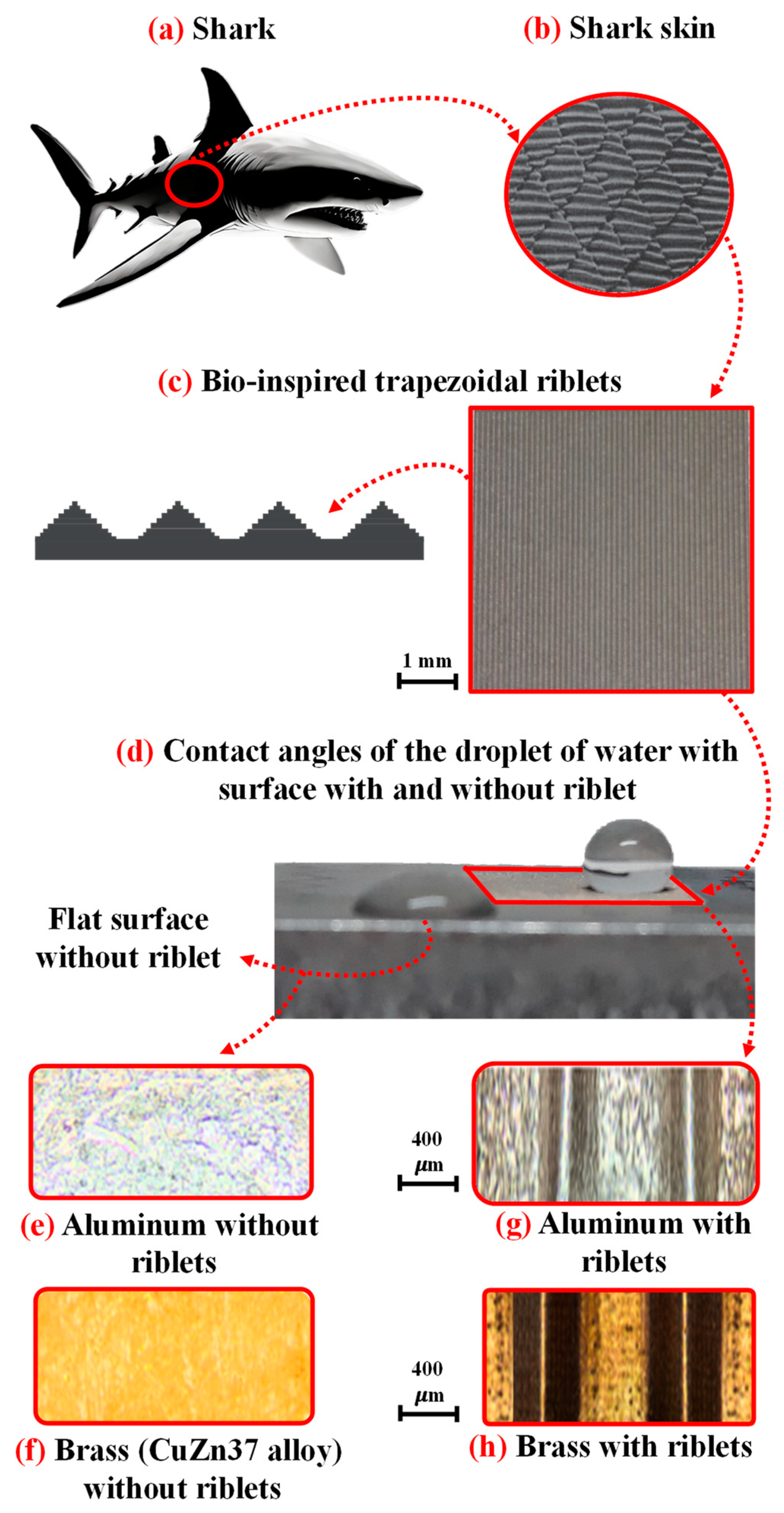
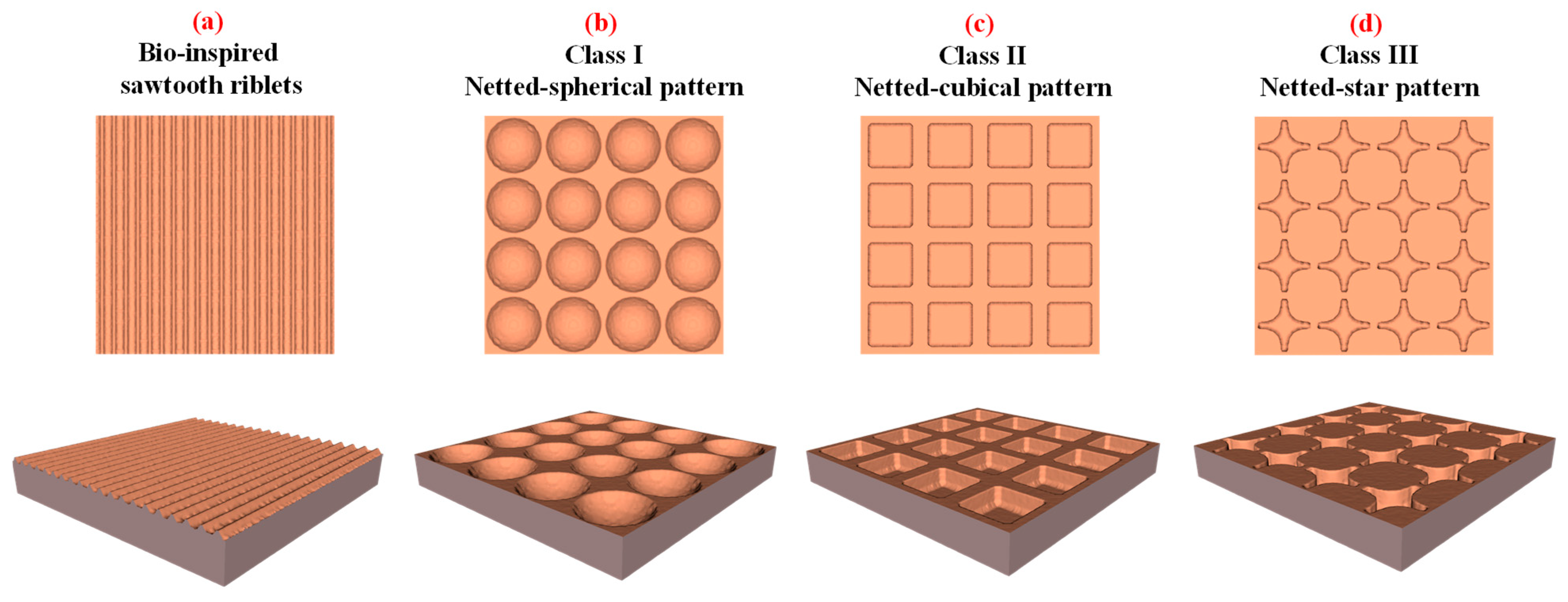
3.1. Solid Boundary without and with Bio-Inspired Sawtooth Riblets

To reveal the effects of riblets and the material of the solid boundary on erosion, Al and brass (CuZn37 alloy; 63% Cu and 37% Zn) materials, with and without riblets, have been considered for cavitation testing. Figure 2 depicts the schematic of the shark-skin trapezoidal riblet pattern applied to the surfaces of Al and brass. As observed in this figure, the trapezoidal riblets are biologically inspired by shark-skin patterns (Figure 1a–c). The trapezoidal riblets provide hydrophobic characteristics [32] because the contact angle of a water droplet on the ribleted surface ranges between 90° and 180° (Figure 2d). In contrast, the flat surface without riblets is hydrophilic [32], with a contact angle between 0° and 90° (Figure 2d). Figure 2e and Figure 2f demonstrates the flat surfaces of Al and brass without riblets, respectively. Conversely, Figure 2g and Figure 2h shows the surface morphology of Al and brass with riblets, respectively. Subsequently, these slabs were submerged in water, and bubbles created with a laser were used to perform erosion tests, based on bubble collapse. More information concerning the geometry of the riblets, the fingerprint of the materials, and the physical parameters can be found in the relevant literature [17].

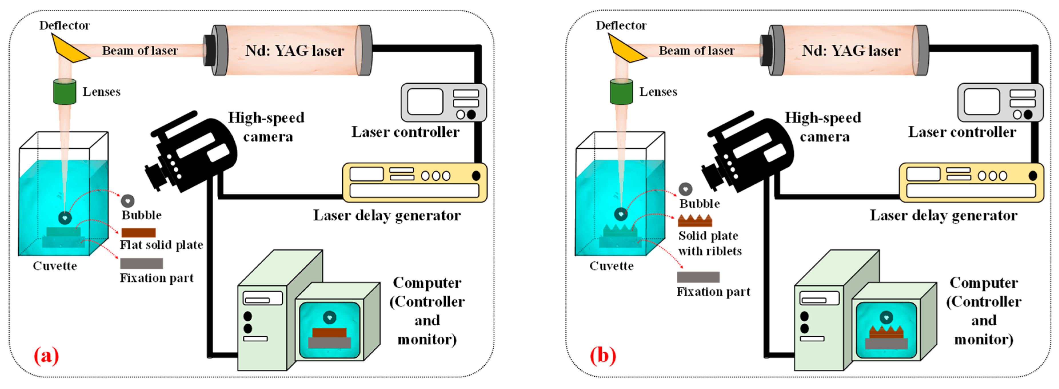
3.2. Experimental Methodology

Figure 3a,b illustrates the arrangement of the experimental setup utilized to generate a single cavitation bubble near a rigid surface, without and with riblets, in separate experiments, respectively. The primary flow control in the cavitation experiment is achieved using a laser delay generator and a laser controller with an Q-switch Nd:YAG Litron laser (Litron Lasers, Rugby, UK). The laser beam is then deflected and focused by a deflector and lenses, respectively, inside a cuvette filled with water to create a single bubble. Finally, the bubble collapses, and the collapse dynamics are recorded using a high-speed camera and monitored by a computer. The wavelength and pulse duration of the laser are 1.064 nanometers (nm) and 4 nanoseconds (ns), respectively. Moreover, the laser produces a maximum output energy of 400 millijoules (mJ) and a maximum repetition rate of 10 hertz (Hz).
A single bubble, with a Rmax of approximately 1.5 millimeters (mm) and a standard spatial deviation of 14 micrometers (μm), can be generated with a laser beam energy level of approximately 14.6 mJ, obtained using an adjustable laser controller. This magnitude of energy helps to create bubbles without causing significant turbulence in the water. Inside the cuvette at the focal region of the lens, the energy and convergence of the laser beam generate high-temperature plasma close to the solid boundary. This causes the water in the plasma region to evaporate, leading to the creation of a single cavitation bubble with wall distance of γ = 1.8 (dimensionless). This value was selected because, at this distance, the bubble collapse time was reduced in the presence of riblets compared to that of a flat surface, helping to clearly reveal the effects of riblets [9]. The growth and collapse processes of the bubble were recorded using a Phantom v9.1 high-speed camera (Adept Turnkey, Osborne Park, Australia), with a sampling rate of 20 kHz and a resolution of 288 × 192 pixels. An internal high-speed controller and an external pulse/delay generator were coupled to trigger the camera with an exposure time of 10 µs.
After the growth of the bubble, its volume shrinks, and the collapse phenomenon occurs near the rigid surface due to the bubble–rigid surface interaction. The collapse process results in the formation of a water jet and hammer, which impact the rigid surface and lead to erosion. To obtain visible erosion, the cavitation-induced erosion generated by the collapse of the bubble was repeated five hundred times near the flat and ribleted surfaces. All experiments were performed at a temperature of 20 degrees Celsius and a pressure of 101 kilopascals (kPa), which are well-known atmospheric conditions. After performing all five hundred bubble collapses, the damage on the surfaces of Al and brass, with and without riblets, was analyzed using a confocal microscope. Subsequently, three-dimensional microscope maps of the damaged surface, optical microscope images, three-dimensional topographies of the damaged surface, and depth versus width diagrams were determined.

4. Results and Discussion

This section provides insight into erosion morphology, shape, and depth to reveal the influence of materials and riblets on erosion and the intensity of the formed holes. The bubble collapse phenomena, which have been experimentally [17,18,36,37] and numerically [21,22,28,38] investigated in previous research by Kadivar et al., are not addressed here; only the erosion and surface damage are examined. More details concerning bubble collapse dynamics can be found elsewhere. In this study, a three-dimensional map of the eroded surface, as well as depth diagrams, were obtained and plotted for both Al and brass surfaces. To perform the cavitation test, 500 repeated single bubbles, with a wall distance of γ = 1.8 (dimensionless), were collapsed near the Al and brass surfaces. Images of the eroded flat and ribleted surfaces were then captured for analysis. This strategy can identify the effects of material and riblets on erosion intensity. More information concerning the effects of wall distance on erosion intensity can be found in the study by Sagar [39]. However, the current research only considered a single relative wall distance equal to γ = 1.8.
In the case of erosion, it can occur through material loss [31], cavitational erosion [22,31], and corrosion [21,31]. In the material loss process, typically called wear, materials in the erosion region are lost due to the mechanical interaction between the slabs and the liquid fluid. In cavitational erosion, the physical structure of the slabs is compressed and dislocated due to the impulse of the water hammer. This process creates pits by pushing down the surface and distorting the lattice of the slabs. In corrosion, the fresh surface of the slab undergoes chemical reactions with the liquid, forming new materials while simultaneously pushing down the surface of the slabs. The products of the reaction accumulate inside and around the pits. However, the rate of chemical reaction depends on the cathodic environment and time.

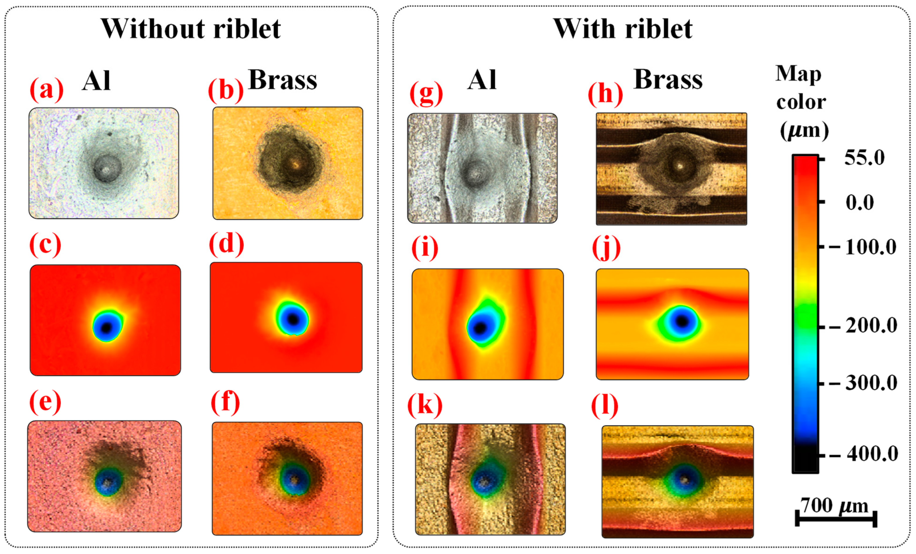
4.1. The Effects of the Material and Riblet on Cavitation-Induced Erosion Morphology

Figure 4 compares the captured optical microscope images, maps, and three-dimensional topographies of the damaged surfaces, obtained using a confocal microscope. This comparison provides the necessary analysis to identify the effects of material and surface morphology on cavitation-induced erosion caused by multiple single bubble collapses. Figure 4 shows the relevant microscopic images of the eroded surfaces of Al and brass side by side to provide sufficient conditions for comparing erosion intensity. The color map depicted on the right of this figure shows the color contours for the maps and the three-dimensional topographies of the damaged surfaces, which can be observed in Figure 4c–f,i–l. The optical microscope images are also indicated in Figure 4a,b,g,h.
Figure 4a and Figure 4b shows the optical microscope images of the eroded Al and brass surfaces without riblets, respectively. Based on these photos, it can be concluded that the cavitation-induced damage shape caused by bubble collapse resembles a rounded cone. Generally, the cross-section of erosion is circular because the water hammer front wave, formed subsequent to the water jet and the complete collapse of the bubble, provides a semi-spherical shape, and its two-dimensional map is circular on the surface. Therefore, the initial eroded area mimics a circular shape. More information regarding water hammer formation subsequent to the water jet and the complete collapse of the bubble can be found in detail elsewhere [9,17,22,28]. This research focuses only on the damage caused by the water hammer on the surface. Creating a single bubble at the same position and repeatedly collapsing it leads to deep erosion growth, ultimately resulting in an erosion shape that mimics a rounded cone with a circular cross-section.
The intercomparison of erosion shapes for Al and brass with riblets in Figure 4g and Figure 4h, respectively, reveals a similar erosion morphology to that of surfaces without riblets. However, the erosion occurs between two riblet lines due to the initial experimental setup, and it seems that the erosion area and depth are decreased in comparison to those of flat surfaces. The similar shape of erosion originates from the similar collapse characteristics of the water hammer and jet in the presence and absence of riblets. Because the bubble collapse dynamics, formed water jet, and water hammer near the flat and ribleted surfaces are similar, the erosion shapes on flat and ribleted surfaces resemble rounded cones, with circular cross-sections. In contrast, the lower erosion depth and area on ribleted surfaces result from the effects of riblets on the bubble collapse time and the momentum of the water hammer and jet. Riblets can decrease the bubble collapse time and reduce the momentum carried by the water jet and hammer [9,17,29], resulting in a lower erosion depth and area.
Maps of the damaged surfaces without riblets for Al and brass are depicted in Figure 4c,d to provide more evidence of erosion morphology and depth. Based on these figures, the erosion area can be divided into five regions. The first region, with a semi-circular shape, which is well-known as the cross-section of a cone, shows a depth between 0 to 100 μm. The second region, with a lower cross-sectional area and yellow color, indicates a depth of approximately 150 μm. The third and fourth regions, in green and blue colors, correspond to depths of 200 μm and 300 μm, respectively. Finally, the fifth region, with a navy blue color and a depth of 330–450 μm, identifies the approximate depth of the erosion. In the case of Al and brass with riblets, as shown in Figure 4i,j, it is clear that the morphology of the erosion is similar to that of flat surfaces. However, in the fifth region, the depth of the erosion decreases to 315–416 μm.
Figure 4e and Figure 4f compare the three-dimensional topography of the damaged Al and brass surfaces without riblets, respectively. These figures show that the final depth of erosion for flat Al and brass surfaces, indicated by the navy blue color, is approximately 330–450 μm. In contrast, for the ribleted surfaces of Al and brass shown in Figure 4k and Figure 4l, respectively, the final depth of erosion is in the range of 315–316 μm, also indicated by the navy blue color. An intercomparison of the final erosion depth between Al and brass surfaces with and without riblets reveals that the erosion depth decreases in the presence of riblets. This is because riblets can decrease the momentum of the water hammer formed toward the surface following bubble collapse by causing the separation of water vortices formed during the collapse. Consequently, the impulse of the water hammer decreases, reducing erosion.
In summary, it is clear that erosion depth decreases in the presence of riblets because riblets can separate the water vortices, thereby decreasing the impulse of the water hammer. Moreover, the erosion morphology reveals a rounded cone with a circular cross-section. Furthermore, the circular cross-sectional area and depth of erosion decrease and increase, respectively, along the axis of the cone. The circular cross-sectional area is formed due to the two-dimensional impulse map of the water hammer. The decrease in the circular area of the cross-section along the axis of the cone is due to the increasing wall distance of the bubble as the depth of the eroded region grows after repeated collapses. For several initial bubble collapses, the fresh surface stands against the water hammer, and the maximum concentration of the water hammer impact on the surface leads to significant erosion with a circular shape. However, as erosion occurs and grows with repeated collapses, the distance between the depth of erosion and the center of the bubble increases, leading to a rise in wall distance and reducing the impulse of the water hammer on the surface. In this case, only the front part of the water hammer impacts the surface, resulting in a smaller circular cross-sectional erosion with a circular shape. On the other hand, repeated bubble collapses lead to continuous impulse and increase the erosion depth along the cone axis.

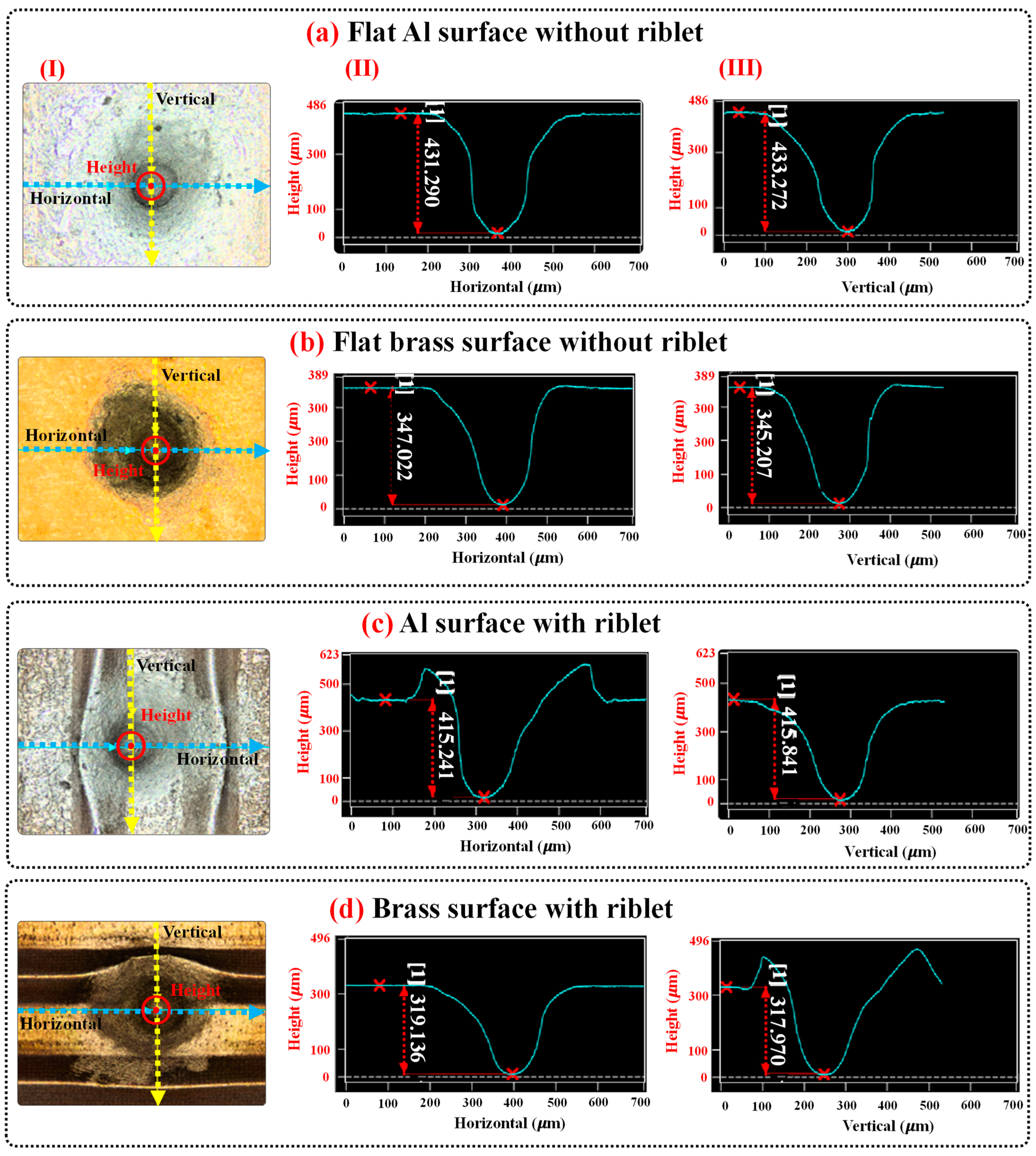
4.2. The Effects of the Material and Riblets on Cavitation-Induced Erosion Depth and Cross-Section

The previous section provides precise information concerning the effects of the material and riblets on cavitation-induced erosion morphology; however, the exact amount of cross-sectional area of erosion remains unclear, and the depth of erosion is expressed within the range of 330–450 μm and 315–316 μm for flat and ribleted surfaces, respectively. In this regard, this section offers a three-dimensional map of the eroded surface and a diagram of depth to disclose the exact amount of cross-sectional area and the depth of erosion, as shown in Figure 5. This figure presents a three-dimensional map of the eroded surface, a diagram of the depth versus width of the damaged surface along the horizontal line, and a diagram of the depth versus width of the damaged surface along the vertical line induced by 500 single cavitation bubbles with a wall distance of γ = 1.8 in parts I, II, and III, respectively.
Figure 5a illustrates the average depth of erosion of 432.281 μm and an average radius of the cross-section of erosion of 162.5 μm for Al with a flat surface. Intercomparison of these values with the average depth (346.115 μm) and radius (157.5 μm) of the cross-section of erosion for brass with a flat surface in Figure 5b reveals that both the depth and area of erosion in brass are smaller than those in Al by 19.9% and 3.0%, respectively. These results originate from the nature of the physical properties of Al and brass. Brass exhibits a Young’s modulus of 97 gigapascals (GPa), a shear modulus of 37 GPa, and a Poisson’s ratio of 0.34 (dimensionless) [40]. In comparison, Al has a Young’s modulus of 68 GPa, a shear modulus of 25 GPa, and a Poisson’s ratio of 0.33 [40]. Intercomparison of these values proves that brass offers greater mechanical stability than Al, with the ability able to tolerate the impulse of the water hammer more effectively than Al and resulting in a lower erosion depth and area in comparison to those of Al.
Based on the obtained results for the exact amount of cross-sectional area and depth of erosion in the case of Al and brass with flat surface morphology, it can be expected that in the presence of riblets, the erosion area and depth for brass will be lower than for Al. Intercomparison of the average depth and radius of the cross-section of erosion for Al and brass with riblets in Figure 5c and Figure 5d, respectively, confirms this prediction. According to these figures, the average depth of erosion for Al and brass with riblets are 415.541 and 318.553 μm, respectively. These outcomes clearly indicate that brass with riblets exhibits 23.3% less erosion compared to that of Al with riblets. Moreover, in the presence of riblets, the erosion depth of Al and brass is reduced by 3.8% and 7.9%, respectively, in comparison with that for flat surfaces. Furthermore, the erosion depth of brass is lower than that of Al when both have surfaces with riblets.
Intercomparison of the erosion width along horizontal and vertical axes for surfaces with and without riblets in Figure 5 indicates that the width of erosion perpendicular to the riblet lines decreases, while this value parallel to the riblet lines remains similar to those observed for flat surfaces. The widths of erosion parallel to the riblet lines are 350 μm and 322 μm for Al and brass with riblets, respectively. Comparing these values with the width of erosion for Al (350 μm) and brass (320 μm) without riblets shows that riblets along their lines do not affect water vortices and thereby do not decrease erosion width. More information regarding water vortices can be found elsewhere [21,41,42]. On the other hand, completely different results are observed perpendicular to the riblet lines. It is evident that the width of erosion perpendicular to the riblet lines for Al and brass with riblets are 245 μm and 225 μm, respectively. Intercomparison of these results with the values for Al (300 μm) and brass (310 μm) without riblets signifies that the presence of riblets reduces the width of erosion by 18.3% and 27.4% for Al and brass, respectively. This outcome is attributed to the riblets, as perpendicular to riblet lines, the water vortices separate, and the impulse of the water hammer decreases along this axis, thereby reducing the width of erosion.
This section outlines the significant effects of material type and riblets on erosion. Brass exhibits 21.6% greater erosion resistance compared to Al due to its mechanical stability. In other words, brass experiences less erosion than Al because of its inherent physical properties. Riblets reduce the depth and width of erosion by 3.8% and 18.3%, respectively, for Al. In the case of brass, riblets decrease the depth and width of erosion by 7.9% and 27.4%, respectively. The width of erosion perpendicular to the riblet lines decreases more than that for erosion parallel to riblet lines due to the separation effects of water vortices. Therefore, it can be concluded that riblets can provide anti-erosion properties for materials against fluid and cavitation damage.

5. Outlook and Perspective

In this research, the influence of materials (Al and brass) and bio-inspired sawtooth riblets on cavitation-induced erosion morphology, depth, and cross-sectional area has been investigated using experimental approaches. The main findings of this study reveal that erosion depth and cross-sectional area are reduced due to the effects of bio-inspired sawtooth riblets. Additionally, brass demonstrates greater erosion resistance compared to Al, with a 7.9% reduction in depth and a 27.4% reduction in erosion width, compared to a 3.8% reduction in depth and an 18.3% reduction in erosion width for Al. This is attributed to the greater mechanical stability of brass. Moreover, results show that the width of erosion perpendicular to the riblet lines decreases more than that for erosion parallel to the riblet lines. These findings are attributed to the physical properties of the materials and the passive erosion control method provided by the riblets. However, in seawater, which represents the primary application of anti-erosion materials for ship and submarine propellers and hulls, materials are exposed to a cathodic environment that leads to corrosion [43,44,45]. Therefore, it is necessary to determine the behavior of riblet direction in, as well as the impact of the cathodic environment on, propellers and hulls.
To address this issue, the following subsections compare the results obtained in this study with prior available data to highlight the contributions of the current work. They also explain the effects of riblet morphology to propose potential new patterns for decreasing erosion and discuss the effects of cathodic environments to provide more accurate data concerning erosion in real seawater situations. It is worth mentioning that the effects of temperature or its limitations in this study have not addressed because previous research has extensively covered these aspects. Previous studies have thoroughly investigated the effects of temperature on bubble dynamics [18,22], the collapse process [18,22], cavitation [18,46,47,48], and induced erosion [22].

5.1. Comparing Obtained Results with Prior Available Data

Table 1 compares the results obtained in the current research with previously available data to clarify the contributions of the present work and to reveal the impacts of materials and surface morphology on erosion induced by cavitating bubbles. This table indicates that most studies have been conducted on metals and their alloys exhibiting flat surfaces [10,49,50,51,52]. While these studies may provide benchmarks for comparing the erosion resistance of materials and their alloys, the comparisons are often inaccurate due to differing experimental conditions (e.g., bubble radius and wall distance). Furthermore, since the effects of surface morphology are ignored in these studies, it is difficult to determine the impact of surface morphologies. Conversely, studies focusing on surfaces with riblets reveal the effects of riblets on erosion but do not compare their data with those for erosion depth and radius on flat surfaces [9,17,53].
There are other studies that providing practical approaches for predicting erosion induced by cavitation bubbles, as well as examining cavitation thermodynamics, lengths, and regimes [46,47,48,54,55]. The erosive power method [54], which predicts cavitation erosion on propellers based on computational fluid dynamics [56], is a suitable strategy for investigating the effects of materials and surface morphology. However, some nanoscale phenomena present in reality may be lost in this approach. Venturi-type cavitation reactors can also be used successfully to investigate cavitation thermodynamics, lengths, and regimes [46,47,48,55]. These reactors, equipped with high-speed video or particle image velocimetry methods using the suppression techniques of hydrodynamic cavitation and thermodynamic effects, can accurately monitor periodic single-cloud cavitation, aperiodic multi-cloud cavitation, cavitation dynamics, lengths, and regimes under different temperature and pressure conditions. However, these methods have not reported fingerprints of erosion and corrosion.
In sum, the intercomparison and review of the data provided in Table 1 reveal that material, surface morphology, and thermodynamic conditions can affect erosion induced by cavitation bubbles [9,10,17,49,50,51,52,53]. Additionally, various experimental setups can offer more details regarding cavitation [46,47,54]. However, it is difficult to precisely determine the effects of surface morphology and material on the mitigation of erosion because all of these data were obtained under different conditions. To address these issues, the current study compares the effects of Al and brass materials, with and without riblets, on the mitigation of erosion under similar conditions. This strategy enables an accurate comparison of the material and surface morphology for erosion resistance applications. The results show that brass, both with and without riblets, provides greater erosion resistance compared to that of Al.

5.2. Riblets Morphology

In the case of riblets morphology, the geometry and pattern of the riblets can significantly influence the degree of erosion reduction. The height of the riblets, the angles of the V-shaped sawtooth, and the distance between the riblet lines should be designed considering the most probable bubbles near the propellers and hulls. Bubbles of different radii can produce various water jets and hammers, resulting in different impulses and erosions. Each water hammer, depending on its volume and momentum, causes a specific impulse and erosion pattern. The term “erosion pattern” refers to the specific shapes of erosion formed on the surface. At the interface between propellers (or hulls) and seawater, different riblet geometries lead to varying effects on the separation of water vortices, thus affecting erosion reduction. Therefore, the morphology of the riblets should be designed considering the most probable bubble characteristics to offer high erosion resistance.
The orientation pattern of riblet lines is another geometric factor that can be useful in reducing erosion. The results obtained in the current study indicate that the width of erosion perpendicular to the riblet lines decreases more than that parallel to the riblet lines, as illustrated in Figure 6a. It can be predicted that if a netted pattern is considered for riblets, the erosion width could be limited in both the perpendicular and parallel directions. The schematic of the netted pattern is depicted in Figure 6b–d. It is worth mentioning that in a netted pattern, the height, angles, and size of the netted cells must be designed with regard to the most probable bubbles near the propellers and hulls to offer maximum erosion resistance. These patterns can be applied to the surface of the material using micro [57] and electron beam drilling [58] techniques. Evidence of the positive effects of netted pattern riblets on erosion reduction can initially be investigated through molecular dynamics and finite element methods. Subsequently, experimental approaches can be utilized. This strategy can not only be useful to prove the effects of the netted pattern riblets on erosion resistance, but also decrease the cost of research validation.

5.3. The Effects of the Cathodic Environment

In seawater, propellers and hulls are submerged in a cathodic environment where chemical reactions and erosion occur simultaneously [43,44,45], a process known as corrosion. This study investigated the effects of materials and riblets on erosion; however, the effects of chemical reactions were not addressed. Therefore, it is necessary to consider the probable chemical reactions, which significantly depend on the materials, as an influencing parameter in corrosion. Investigation of corrosion can be performed using cost-effective reactive molecular dynamics (reactive-MD) [21] and density functional theory (DFT) [59] methods, as well as experimental techniques [60]. These methods can successfully reveal the probable chemical reactions. For example, regarding the reaction of Al [21] and brass (Cu-20Zn) [60] with pure water, the following equation can be expected.
For Al:  2Al(s) + H2O(l) → AlOH(s) + AlH(s)
For Brass:  Brass(Cu-20Zn)(s) + 2H2O (l) → Cu2O(s) + ZnO(s) + 2H2(g)
Here, s denotes the solid, l signifies the liquid, and g depicts the gas phases. H2O, AlOH, and AlH represent water, aluminum monohydroxide, and aluminum monohydride, respectively. Cu2O is cuprous oxide, ZnO represents zinc oxide, and H2 indicates the hydrogen gas. Based on Equations (1) and (2), it is evident that Al and brass can corrode when they come into contact with pure water. Similarly, chemical reactions occur under cathodic environments, producing chemical products and decreasing the lifetime of materials. Therefore, the corrosion process (erosion + chemical reaction) under cathodic environments should be addressed for Al and brass to provide a comprehensive overview of the sufficiency of these materials in regards to corrosion resistance.

6. Conclusions

Erosion of propellers and hulls is a critical issue in the shipping industry, significantly reducing the lifespan of components in seawater. Offering erosion-resistant materials to control and reduce erosion can increase the lifespan of these components and reduce repair and maintenance costs. In this regard, the effects of materials (Al and brass) and bio-inspired sawtooth riblets on cavitation-induced erosion morphology, depth, and cross-sectional area have been probed through experimental methods to provide scientific and comparable insights into erosion. These aims were achieved by subjecting Al and brass surfaces, with and without riblets, to 500 single cavitation bubbles, with a wall distance of γ = 1.8, followed by capturing optical microscopic images and depth diagrams of erosion.
The results indicate that for both Al and brass with flat and ribleted surfaces, the erosion morphology resembles a rounded cone with a circular cross-section. However, the height of the cone axis (erosion depth) and the cross-sectional area of the erosion depend on the material and the presence of riblets. Initially, erosion begins with a large circular cross-sectional area, and as the depth of erosion increases, the cross-sectional radius decreases. In other words, the increasing depth of erosion along the cone axis results from multiple bubble collapses and the subsequent multiple impulses of water hammers. This process decreases the cross-sectional area of erosion due to the increasing wall distance of the bubble as the depth of the eroded region grows after repeated collapses.
In terms of material properties, brass provides 21.6% more erosion resistance compared to that of Al due to its mechanical stability. Regarding the riblets, employing Al with riblets reduces the depth and width of erosion by 3.8% and 18.3%, respectively, compared to using Al with a flat surface. In contrast, employing brass with riblets decreases the depth of erosion by 7.9% and the width by 27.4% compared to the results for brass without riblets. Concerning riblet geometry, the width of erosion perpendicular to the riblet lines decreases more than the erosion parallel to the riblet lines due to the separation effects of water vortices. The summary of results reveals that materials with durable mechanical stability, when provided with riblets, can significantly decrease erosion. However, the probability of chemical reactions in a cathodic environment and the exploration of other potential riblet patterns should be examined to provide a comprehensive evaluation of corrosion and to achieve maximum erosion intensity reduction.

Author Contributions

Conceptualization, E.K. and O.e.M.; Methodology, E.K., U.L. and O.e.M.; Software, S.R.; Validation, S.R.; Formal analysis, U.L.; Investigation, E.K. and S.R.; Writing—original draft, E.K. and S.R.; Writing—review & editing, E.K., S.R. and U.L.; Supervision, E.K.; Project administration, E.K. All authors have read and agreed to the published version of the manuscript.

Funding

This research received no external funding.

Institutional Review Board Statement

Not applicable.

Informed Consent Statement

Not applicable.

Data Availability Statement

The original contributions presented in the study are included in the article, further inquiries can be directed to the corresponding author.

Conflicts of Interest

The authors declare no competing financial interests or personal relationships that could have influenced the work reported in this paper.

References

  1. Kadivar, E.; Ochiai, T.; Iga, Y.; el Moctar, O. An Experimental Investigation of Transient Cavitation Control on a Hydrofoil Using Hemispherical Vortex Generators. J. Hydrodyn. 2021, 33, 1139–1147. [Google Scholar] [CrossRef]
  2. Kadivar, E.; Timoshevskiy, M.V.; Nichik, M.Y.; El Moctar, O.; Schellin, T.E.; Pervunin, K.S. Control of Unsteady Partial Cavitation and Cloud Cavitation in Marine Engineering and Hydraulic Systems. Phys. Fluids 2020, 32, 052108. [Google Scholar] [CrossRef]
  3. Fortes Patella, R.; Choffat, T.; Reboud, J.L.; Archer, A. Mass Loss Simulation in Cavitation Erosion: Fatigue Criterion Approach. Wear 2013, 300, 205–215. [Google Scholar] [CrossRef]
  4. Sadri, M.; Kadivar, E. Numerical Investigation of the Cavitating Flow and the Cavitation-Induced Noise around One and Two Circular Cylinders. Ocean Eng. 2023, 277, 114178. [Google Scholar] [CrossRef]
  5. Dular, M.; Bachert, B.; Stoffel, B.; Širok, B. Relationship between Cavitation Structures and Cavitation Damage. Wear 2004, 257, 1176–1184. [Google Scholar] [CrossRef]
  6. Reisman, G.E.; Wang, Y.C.; Brennen, C.E. Observations of Shock Waves in Cloud Cavitation. J. Fluid Mech. 1998, 355, 255–283. [Google Scholar] [CrossRef]
  7. Lin, Y.; Kadivar, E.; El Moctar, O.; Neugebauer, J.; Schellin, T.E. Experimental Investigation on the Effect of Fluid-Structure Interaction on Unsteady Cavitating Flows around Flexible and Stiff Hydrofoils. Phys. Fluids 2022, 34, 083308. [Google Scholar] [CrossRef]
  8. Wei, T.; Smith, C.R. Secondary Vortices in the Wake of Circular Cylinders. J. Fluid Mech. 1986, 169, 513–533. [Google Scholar] [CrossRef]
  9. Kadivar, E.; el Moctar, O.; Sagar, H.J. Experimental Study of the Influence of Mesoscale Surface Structuring on Single Bubble Dynamics. Ocean Eng. 2022, 260, 111892. [Google Scholar] [CrossRef]
  10. Philipp, A.; Lauterborn, W. Cavitation Erosion by Single Laser-Produced Bubbles. J. Fluid Mech. 1998, 361, 75–116. [Google Scholar] [CrossRef]
  11. Tomita, Y.; Shima, A. Mechanisms of Impulsive Pressure Generation and Damage Pit Formation by Bubble Collapse. J. Fluid Mech. 1986, 169, 535–564. [Google Scholar] [CrossRef]
  12. Lauterborn, W.; Bolle, H. Experimental Investigations of Cavitation-Bubble Collapse in the Neighbourhood of a Solid Boundary. J. Fluid Mech. 1975, 72, 391–399. [Google Scholar] [CrossRef]
  13. Vogeland, A.; Lauterborn, W. Acoustic Transient Generation by Laser-Produced Cavitation Bubbles near Solid Boundaries. J. Acoust. Soc. Am. 1988, 84, 719–731. [Google Scholar] [CrossRef]
  14. Lindau, O.; Lauterborn, W. Cinematographic Observation of the Collapse and Rebound of a Laser-Produced Cavitation Bubble near a Wall. J. Fluid Mech. 2003, 479, 327–348. [Google Scholar] [CrossRef]
  15. Tomita, Y.; Robinson, P.B.; Tong, R.P.; Blake, J.R. Growth and Collapse of Cavitation Bubbles near a Curved Rigid Boundary. J. Fluid Mech. 2002, 466, 259–283. [Google Scholar] [CrossRef]
  16. Dular, M.; Požar, T.; Zevnik, J.; Petkovšek, R. High Speed Observation of Damage Created by a Collapse of a Single Cavitation Bubble. Wear 2019, 418–419, 13–23. [Google Scholar] [CrossRef]
  17. Kadivar, E.; el Moctar, O.; Skoda, R.; Löschner, U. Experimental Study of the Control of Cavitation-Induced Erosion Created by Collapse of Single Bubbles Using a Micro Structured Riblet. Wear 2021, 486–487, 204087. [Google Scholar] [CrossRef]
  18. Phan, T.H.; Kadivar, E.; Nguyen, V.T.; El Moctar, O.; Park, W.G. Thermodynamic Effects on Single Cavitation Bubble Dynamics under Various Ambient Temperature Conditions. Phys. Fluids 2022, 34, 23318. [Google Scholar] [CrossRef]
  19. Murai, Y.; Matsumoto, Y. Numerical Study of the Three-Dimensional Structure of a Bubble Plume. J. Fluids Eng. Trans. ASME 2000, 122, 754–760. [Google Scholar] [CrossRef]
  20. Xiao, C.; Heyes, D.M.; Powles, J.G. The Collapsing Bubble in a Liquid by Molecular Dynamics Simulations. Mol. Phys. 2002, 100, 3451–3468. [Google Scholar] [CrossRef]
  21. Ghoohestani, M.; Rezaee, S.; Kadivar, E.; Esmaeilbeig, M.A. Reactive-Dynamic Characteristics of a Nanobubble Collapse near a Solid Boundary Using Molecular Dynamic Simulation. Phys. Fluids 2023, 35, 022003. [Google Scholar] [CrossRef]
  22. Ghoohestani, M.; Rezaee, S.; Kadivar, E.; el Moctar, O. Thermodynamic Effects on Nanobubble’s Collapse-Induced Erosion Using Molecular Dynamic Simulation. Phys. Fluids 2023, 35, 073319. [Google Scholar] [CrossRef]
  23. Gao, Z.; Wu, W.; Sun, W.; Wang, B. Understanding the Stabilization of a Bulk Nanobubble: A Molecular Dynamics Analysis. Langmuir 2021, 37, 11281–11291. [Google Scholar] [CrossRef] [PubMed]
  24. Sun, D.; Lin, X.; Zhang, Z.; Gu, N. Impact of Shock-Induced Lipid Nanobubble Collapse on a Phospholipid Membrane. J. Phys. Chem. C 2016, 120, 18803–18810. [Google Scholar] [CrossRef]
  25. Nan, N.; Si, D.; Hu, G. Nanoscale Cavitation in Perforation of Cellular Membrane by Shock-Wave Induced Nanobubble Collapse. J. Chem. Phys. 2018, 149, 074902. [Google Scholar] [CrossRef]
  26. Santo, K.P.; Berkowitz, M.L. Shock Wave Induced Collapse of Arrays of Nanobubbles Located Next to a Lipid Membrane: Coarse-Grained Computer Simulations. J. Phys. Chem. B 2015, 119, 8879–8889. [Google Scholar] [CrossRef] [PubMed]
  27. Adhikari, U.; Goliaei, A.; Berkowitz, M.L. Mechanism of Membrane Poration by Shock Wave Induced Nanobubble Collapse: A Molecular Dynamics Study. J. Phys. Chem. B 2015, 119, 6225–6234. [Google Scholar] [CrossRef]
  28. Rezaee, S.; Kadivar, E.; el Moctar, O. Molecular Dynamics Simulations of a Nanobubble’s Collapse-Induced Erosion on Nickel Boundary and Porous Nickel Foam Boundary. J. Mol. Liq. 2024, 397, 124029. [Google Scholar] [CrossRef]
  29. Rezaee, S.; Kadivar, E.; el Moctar, O. The Role of Sawtooth-Shaped Nano Riblets on Nanobubble Dynamics and Collapse-Induced Erosion near Solid Boundary. J. Mol. Liq. 2024, 405, 124947. [Google Scholar] [CrossRef]
  30. Peters, A. Numerical Modelling and Prediction of Cavitation Erosion Using Euler-Euler and Multi-Scale Euler-Lagrange Methods. Ph.D. Thesis, Universität Duisburg-Essen, Duisburg, Germany, 2020. [Google Scholar]
  31. Liang, L.; Pang, Y.; Tang, Y.; Zhang, H.; Liu, H.; Liu, Y. Combined Wear of Slurry Erosion, Cavitation Erosion, and Corrosion on the Simulated Ship Surface. Adv. Mech. Eng. 2019, 11, 1687814019834450. [Google Scholar] [CrossRef]
  32. Pap, A.E.; Dücso, C.; Kamaras, K.; Battistig, G.; Bársony, I. Heavy Water in Gate Stack Processing. In Proceedings of the Materials Science Forum; Trans Tech Publ: Bäch, Switzerland, 2008; Volume 573–574, pp. 119–131. [Google Scholar]
  33. Hutson, J.; Lively, J.; Robertson, B.; Cotroneo, P.; Lang, M. Expanding Horizons: AI Tools and Workflows in Art Practice. In Springer Series on Cultural Computing; Springer: Cham, Switzerland, 2024; Part F1711; pp. 101–132. [Google Scholar]
  34. Epstein, D.C.; Jain, I.; Wang, O.; Zhang, R. Online Detection of Ai-Generated Images. In Proceedings of the IEEE/CVF International Conference on Computer Vision, Paris, France, 2–6 October 2023; pp. 382–392. [Google Scholar]
  35. Healy, M. Approaches to Generative Artificial Intelligence, A Social Justice Perspective. arXiv 2023, arXiv:2309.12331. [Google Scholar] [CrossRef]
  36. Sagar, H.J.; el Moctar, O. Dynamics of a Cavitation Bubble near a Solid Surface and the Induced Damage. J. Fluids Struct. 2020, 92, 102799. [Google Scholar] [CrossRef]
  37. Kadivar, E.; Phan, T.H.; Park, W.G.; El Moctar, O. Dynamics of a Single Cavitation Bubble near a Cylindrical Rod. Phys. Fluids 2021, 33, 113315. [Google Scholar] [CrossRef]
  38. Kadivar, E.; Rajabpour, A.; El Moctar, O. Nanobubble Collapse Induced Erosion near Flexible and Rigid Boundaries: A Molecular Dynamics Study. Fluids 2023, 8, 154. [Google Scholar] [CrossRef]
  39. Sagar, H.J. Numerical and Experimental Investigation of Laser-Induced Cavitation Bubbles and Induced Damage. Ph.D. Thesis, Universität Duisburg-Essen, Duisburg, Germany, 2018; pp. 430–439. [Google Scholar]
  40. Hussein, N. Materials Science and Engineering; CreateSpace Independent Publishing Platform: Scotts Valley, CA, USA, 2017; Volume 7, ISBN 978-1544083803. [Google Scholar]
  41. Choubey, A.; Vedadi, M.; Nomura, K.I.; Kalia, R.K.; Nakano, A.; Vashishta, P. Poration of Lipid Bilayers by Shock-Induced Nanobubble Collapse. Appl. Phys. Lett. 2011, 98, 23701. [Google Scholar] [CrossRef]
  42. Vedadi, M.; Choubey, A.; Nomura, K.; Kalia, R.K.; Nakano, A.; Vashishta, P.; Van Duin, A.C.T. Structure and Dynamics of Shock-Induced Nanobubble Collapse in Water. Phys. Rev. Lett. 2010, 105, 14503. [Google Scholar] [CrossRef] [PubMed]
  43. Xu, Y.; Zhang, Q.; Zhou, Q.; Gao, S.; Wang, B.; Wang, X.; Huang, Y. Flow Accelerated Corrosion and Erosion−corrosion Behavior of Marine Carbon Steel in Natural Seawater. npj Mater. Degrad. 2021, 5, 56. [Google Scholar] [CrossRef]
  44. Googan, C. Marine Corrosion and Cathodic Protection; CRC Press: London, UK, 2022; ISBN 9781000536492. [Google Scholar]
  45. Yan, Y.; Zhu, H.; Fan, Z.; Zhao, J.; Jiang, S. Corrosion Behavior of Reinforcing Steel in the Immersed Tube Tunnel (ITT) under Submarine Environment. Materials 2023, 16, 3300. [Google Scholar] [CrossRef] [PubMed]
  46. Ge, M.; Manikkam, P.; Ghossein, J.; Kumar Subramanian, R.; Coutier-Delgosha, O.; Zhang, G. Dynamic Mode Decomposition to Classify Cavitating Flow Regimes Induced by Thermodynamic Effects. Energy 2022, 254, 124426. [Google Scholar] [CrossRef]
  47. Ge, M.; Zhang, G.; Petkovšek, M.; Long, K.; Coutier-Delgosha, O. Intensity and Regimes Changing of Hydrodynamic Cavitation Considering Temperature Effects. J. Clean. Prod. 2022, 338, 130470. [Google Scholar] [CrossRef]
  48. Ge, M.; Petkovšek, M.; Zhang, G.; Jacobs, D.; Coutier-Delgosha, O. Cavitation Dynamics and Thermodynamic Effects at Elevated Temperatures in a Small Venturi Channel. Int. J. Heat Mass Transf. 2021, 170, 120970. [Google Scholar] [CrossRef]
  49. Naudé, C.F.; Ellis, A.T. On the Mechanism of Cavitation Damage by Nonhemispherical Cavities Collapsing in Contact with a Solid Boundary. J. Basic Eng. Trans. 1961, 83, 648–656. [Google Scholar] [CrossRef]
  50. Neville, A.; McDougall, B.A.B. Erosion—And Cavitation—Corrosion of Titanium and Its Alloys. Wear 2001, 250, 726–735. [Google Scholar] [CrossRef]
  51. Dular, M.; Delgosha, O.C.; Petkovšek, M. Observations of Cavitation Erosion Pit Formation. Ultrason. Sonochem. 2013, 20, 1113–1120. [Google Scholar] [CrossRef] [PubMed]
  52. Chahine, G.L.; Franc, J.P.; Karimi, A. Mass Loss and Advanced Periods of Erosion. Fluid Mech. Appl. 2014, 106, 97–121. [Google Scholar] [CrossRef]
  53. Chiu, K.Y.; Cheng, F.T.; Man, H.C. Evolution of Surface Roughness of Some Metallic Materials in Cavitation Erosion. Ultrasonics 2005, 43, 713–716. [Google Scholar] [CrossRef] [PubMed]
  54. Usta, O.; Korkut, E. Prediction of Cavitation Development and Cavitation Erosion on Hydrofoils and Propellers by Detached Eddy Simulation. Ocean Eng. 2019, 191, 106512. [Google Scholar] [CrossRef]
  55. Ge, M.; Sun, C.; Zhang, G.; Coutier-Delgosha, O.; Fan, D. Combined Suppression Effects on Hydrodynamic Cavitation Performance in Venturi-Type Reactor for Process Intensification. Ultrason. Sonochem. 2022, 86, 106035. [Google Scholar] [CrossRef]
  56. Sadri Mofakham, A.; Rasteh, M. CFD Simulation of Gas-Solid Fluidized Bed Hydrodynamics; Prediction Accuracy Study. Int. J. Chem. React. Eng. 2023, 21, 391–407. [Google Scholar] [CrossRef]
  57. Hasan, M.; Zhao, J.; Jiang, Z. A Review of Modern Advancements in Micro Drilling Techniques. J. Manuf. Process. 2017, 29, 343–375. [Google Scholar] [CrossRef]
  58. Howitt, D.G.; Chen, S.J.; Gierhart, B.C.; Smith, R.L.; Collins, S.D. The Electron Beam Hole Drilling of Silicon Nitride Thin Films. J. Appl. Phys. 2008, 103, 024310. [Google Scholar] [CrossRef]
  59. Johnson, P.A.; Bartolotti, L.J.; Ayers, P.W.; Fievez, T.; Geerlings, P. Charge Density and Chemical Reactions: A Unified View from Conceptual DFT. In Modern Charge-Density Analysis; Springer: Dordrecht, The Netherlands, 2012; pp. 715–764. ISBN 9789048138364. [Google Scholar]
  60. Qiu, P.; Leygraf, C. Initial Oxidation of Brass Induced by Humidified Air. Appl. Surf. Sci. 2011, 258, 1235–1241. [Google Scholar] [CrossRef] [PubMed]
Figure 1. The schematic illustrates the single bubble collapse process near a flat solid boundary, depicting the maximum radius (Rmax) of the bubble and the distance (h) between the center of the bubble and the surface of the solid boundary. (a) The complete single bubble near a flat solid boundary. (b) The collapse process initiates, and the upper wall of the bubble deteriorates more rapidly than the lower wall near the solid surface. This process is attributed to the formation of water vortices. (c) The number of water vortices increases and converges into an arc shape, thereby decreasing the volume of the bubble. This phenomenon leads to the creation of a water jet. (d) The water jet forms, and its volume increases as new water vortices are added, slicing through the volume of the bubble. Consequently, the water hammer is created and collides with the solid surface, resulting in erosion. (e) After erosion, the flow of water vortices leads to the creation of microbubbles. (f) The volume of the microbubble decreases and converts into nanobubbles. These nanobubbles can migrate through the matrix and collapse upon impact with the solid surface. Therefore, new nano erosion can occur.
Applsci 14 06452 g001
Figure 2. The application of the shark-skin trapezoidal riblet pattern to the surfaces of Al and brass (CuZn37 alloy; 63% Cu and 37% Zn). (a) Schematic of a shark (the portrait of the shark was generated utilizing Adobe Firefly [33,34,35]), (b) magnified shark skin, (c) designing bio-inspired trapezoidal riblets based on the shark skin, (d) the contact angles of a droplet of water with surface, with and without riblet, (e) aluminum surface without riblets, (f) brass surface without riblet, (g) aluminum surface with trapezoidal riblets, and (h) brass surface with trapezoidal riblets.
Applsci 14 06452 g002
Figure 3. The arrangement of the experimental setup utilized to generate a single cavitation bubble near a rigid surface, without and with riblets, in separate experiments, respectively. (a) Experimental setup for flat surface; (b) experimental setup for surface with riblets.
Applsci 14 06452 g003
Figure 4. Microscopic images of Al and brass surfaces, without and with riblets, after 500 single cavitation bubble experiments, with wall distance of γ = 1.8. (a,g) The optical microscopic image of damaged Al surface, without and with riblets, respectively. (b,h) The optical microscopic image of damaged brass surface, without and with riblet, respectively. (c,i) iMap of the damaged Al surface, without and with riblets, respectively. (d,j) represent map of the damaged brass surface without and with riblets, respectively. (e,k) Three-dimensional topography of damaged Al surface, without and with riblets, respectively. (f,l) Three-dimensional topography of damaged brass surface, without and with riblets, respectively. All experiments (cavitation bubble) were performed at a temperature of 20 degrees Celsius and a pressure of 101 kilopascals (kPa), which are well-known atmospheric conditions.
Applsci 14 06452 g004
Figure 5. Three-dimensional map of the eroded surface and diagram of depth. (I) Three-dimensional map of the damaged surface, (II) diagram of depth versus width of the damaged surface along horizontal line, and (III) diagram of depth versus width of the damaged surface along vertical line induced by 500 single cavitation bubble with wall distance of γ = 1.8. (a) Flat Al surface without riblets, (b) flat brass surface without riblets, (c) Al surface with riblets, and (d) brass surface with riblets. All experiments (cavitation bubble) were performed at a temperature of 20 degrees Celsius and a pressure of 101 kilopascals (kPa), which are well-known atmospheric conditions.
Applsci 14 06452 g005
Figure 6. Intercomparison of the bio-inspired sawtooth pattern and proposed riblets. (a) Bio-inspired sawtooth riblets. (b) Proposed class I riblets (netted-spherical pattern). (c) Proposed class II riblets (netted-cubical pattern). (d) Proposed class III riblets (netted-star pattern).
Applsci 14 06452 g006
Table 1. Intercomparison between the results obtained in the current research and prior available data.
ResearchApp.Material FeaturesγResultsYearRef.
Erosion
MaterialSurfaceDepth
(μm)
Diameter
(mm)
Damaging effects of the various cavitiesExp. & The.2S AlFlat0.23-0.3501961[49]
Cavitation bubble in water and the resulting surface damageExp.AlFlat0.3080.5701998[10]
Probing the erosion–corrosion and cavitation–corrosion of Ti alloysExp.Ti alloysFlatThe cavitation–corrosion resistance of Ti alloys are in the sequence of:
Ti–6Al–4V ELI/Ru > Ti–6Al–4V ELI > Ti 5111 > CP-Ti
2001[50]
Evolution of metallic materials (316L stainless steel (SS), CP Ti, and brass) in regards to cavitation erosionExp. 316L SS
Ti
Brass
RoughenedThe erosion resistance of metallic materials is in the sequence of:
316L SS > Ti > Brass
2005[53]
Investigation of the erosion effects of ultrasonic cavitationExp.AlFlat-401.5002013[51]
Probing the advanced stages of erosion characteristicsExp. Ni-Al bronze alloyFlat-4505.0002014[52]
Prediction of cavitation erosion on propellersCFDErosive Power Method (EPM) was proposed to predict of cavitation erosion on propellers2019[54]
Control of cavitation-induced erosion created by collapse of bubbles using ribletsExp.AlRiblet0.932200.0002021[17]
Offering a passive control method to control the dynamics of cavitationExp.AlRiblet0.6–1.8The riblets can suppress the impact of water jets, thereby decreasing erosion2022[9]
Examination the temperature effects on hydrodynamic cavitating flows and intensity of cavitationExp.✓ The pressure drop, inertial/viscous, and temperature condition influence on cavitation lengths and regimes.
✓ Elevated temperatures (over 58 °C) have significant effects on thermodynamic of cavitation.
2022[46,47]
Evaluating the effects of materials on erosion Exp.AlFlat1.8432.2810.3502024Present work
Evaluating the effects of riblets on erosion Exp.AlRiblet1.8415.5410.2452024Present work
Evaluating the effects of materials on erosion Exp.Brass
(CuZn37)
Flat1.8346.1150.3202024Present work
Evaluating the effects of riblets on erosion Exp.Brass
(CuZn37)
Riblet1.8318.5530.2252024Present work
App.: approach; Exp.: experiment; The.: theory; γ: Relative wall distance; CFD: computational fluid dynamics.
Disclaimer/Publisher’s Note: The statements, opinions and data contained in all publications are solely those of the individual author(s) and contributor(s) and not of MDPI and/or the editor(s). MDPI and/or the editor(s) disclaim responsibility for any injury to people or property resulting from any ideas, methods, instructions or products referred to in the content.

