Optimal Area for a Rectangular Isolated Footing with an Eccentric Column and Partial Ground Compression
Abstract
Featured Application
Abstract
1. Introduction
2. Formulation of the Model
- Case I
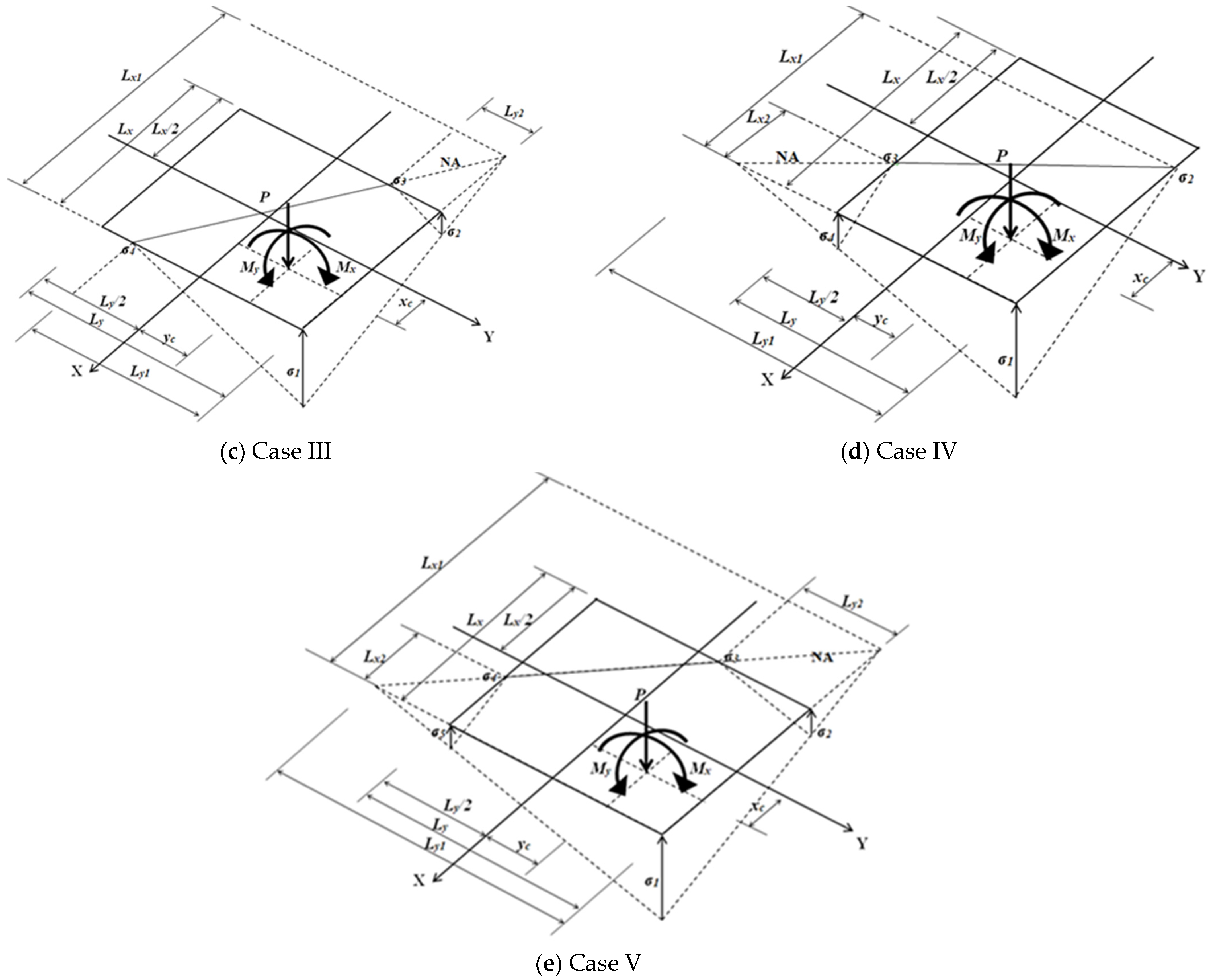
- Case II
- Case III
- Case IV
3. Numerical Problems
4. Results
- For Problem 1.1, the minimum area appears in Case I, and for Problems 1.2, 1.3, and 1.4, the minimum area appears in Case V.
- For Problem 1.2, in terms of the contact area between the footing and the ground, there is no difference (theoretical areas) when using the new model.
- For Problem 1.3, there is a reduction of 2.89% (theoretical areas) in the contact area between the footing and the ground when using the new model.
- For Problem 1.4, there is a reduction of 42.37% (theoretical areas) in the contact area between the footing and the ground when using the new model.
- For Problems 4.1 and 4.2, the minimum area appears in Case I; for Problem 4.3, the minimum area appears in Case V; and for Problem 4.4, the minimum area appears in Case II.
- For Problem 4.3, there is a reduction of 16.88% in the contact area between the footing and the ground when using the new model.
- For Problem 4.4, there is a reduction of 40.32% in the contact area between the footing and the ground when using the new model.
5. Conclusions
- When the columns are very close to each other, the isolated footings tend to overlap. In this case, a combined footing must be used.
- When an isolated footing is limited by space situations (property boundary), a combined footing must be used.
- Other authors propose very complex equations to find the maximum load capacity of the footing due to the soil, and other authors obtain the sides of the footing through iterations.
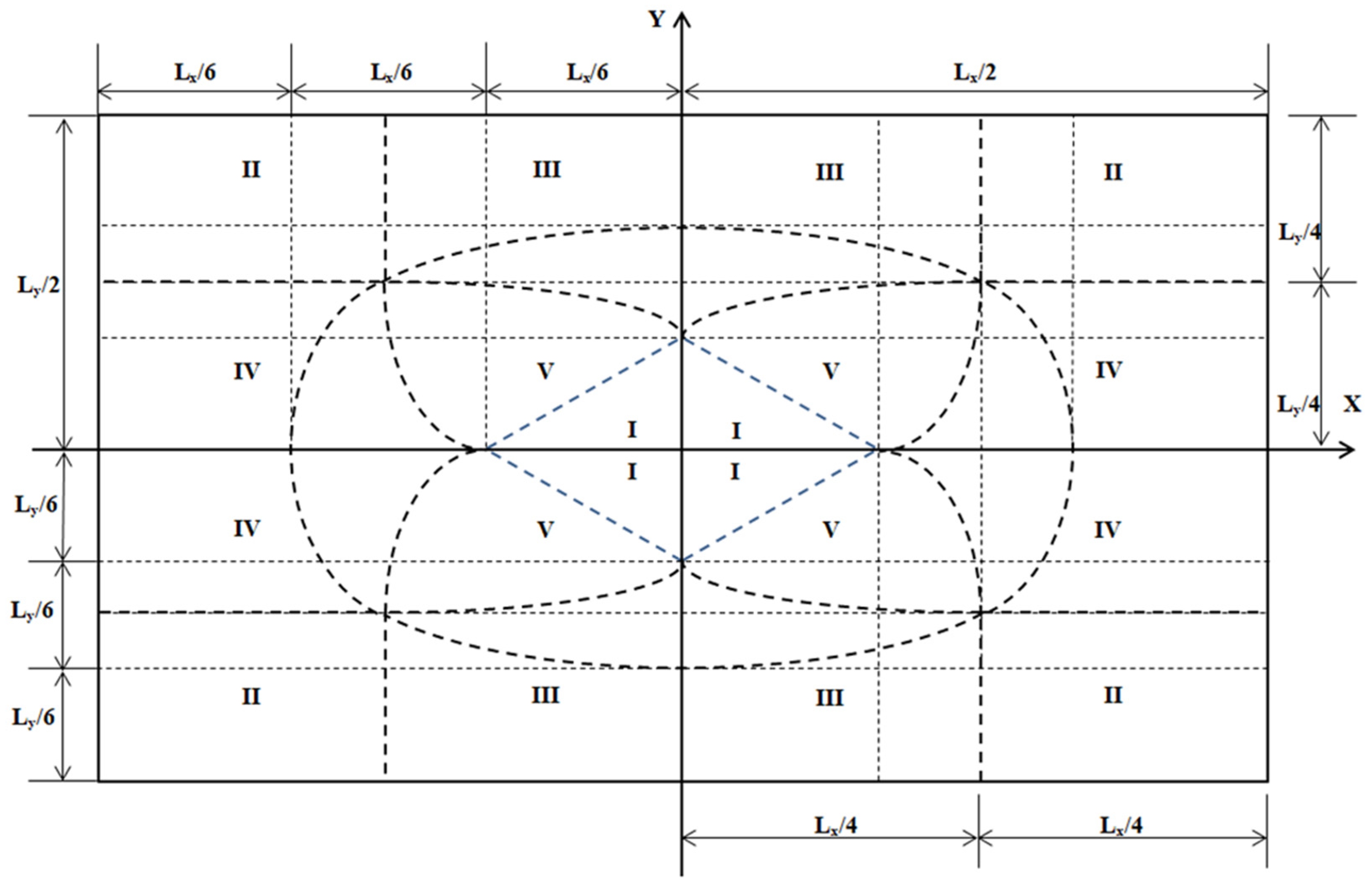
- It is also observed that for the minimum area of the examples considered under biaxial bending, when Case II appears, Case V is not present. This means that when the resultant force decreases, Case II appears, and, conversely, Case V does not appear. This can be seen in Figure 2; when the resultant force is very small, the resultant force tends to fall in zone II. Therefore, it is not possible to obtain a solution for both cases of the same problem.
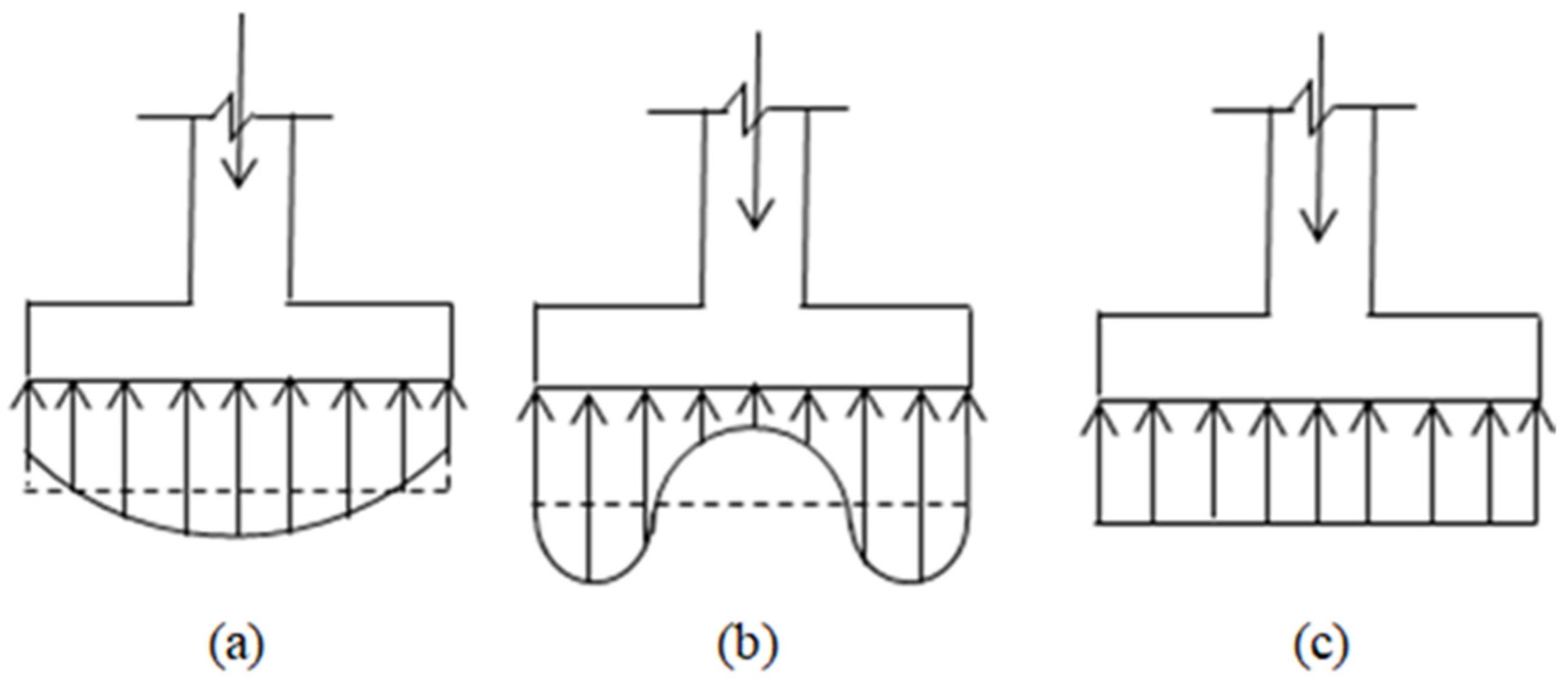
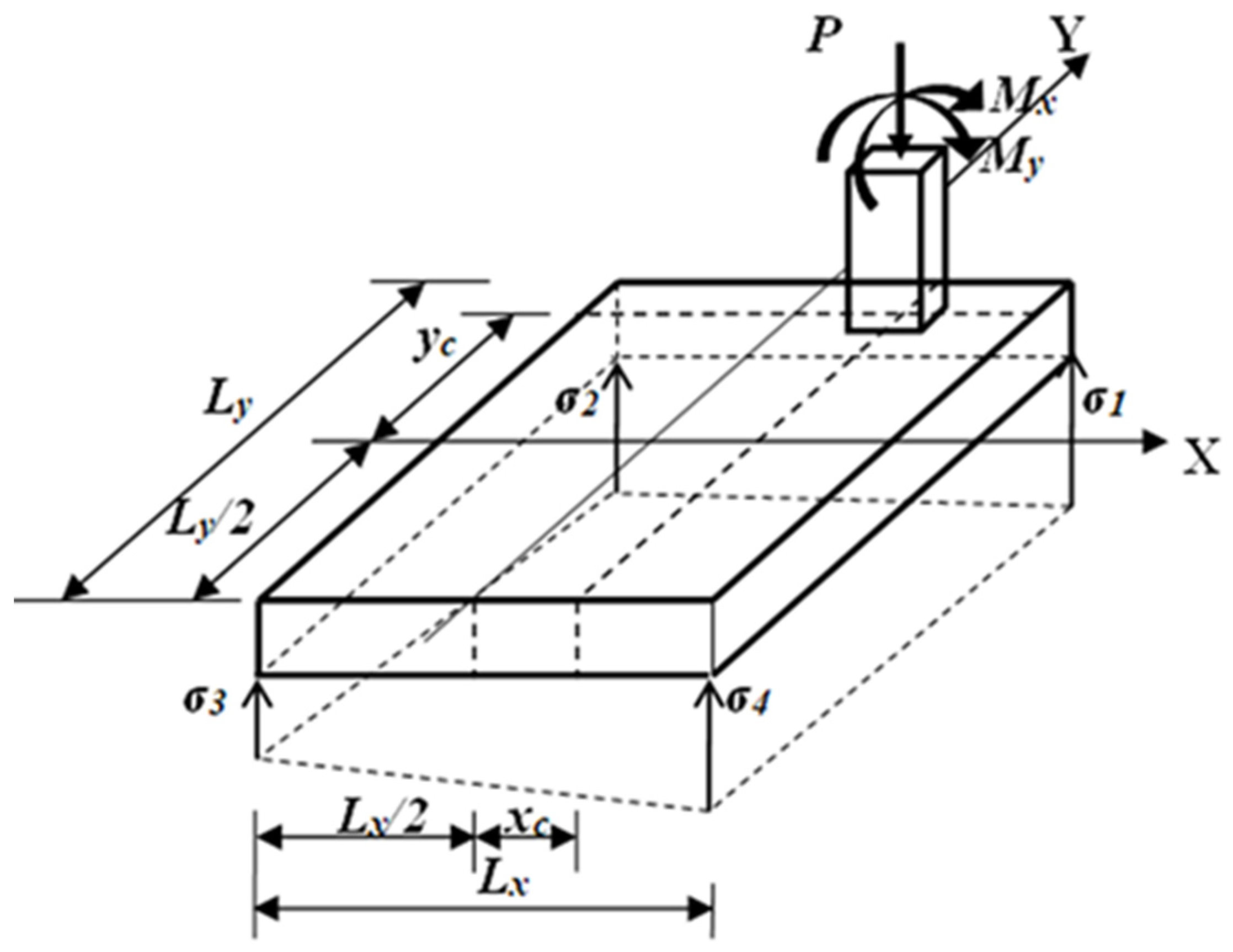
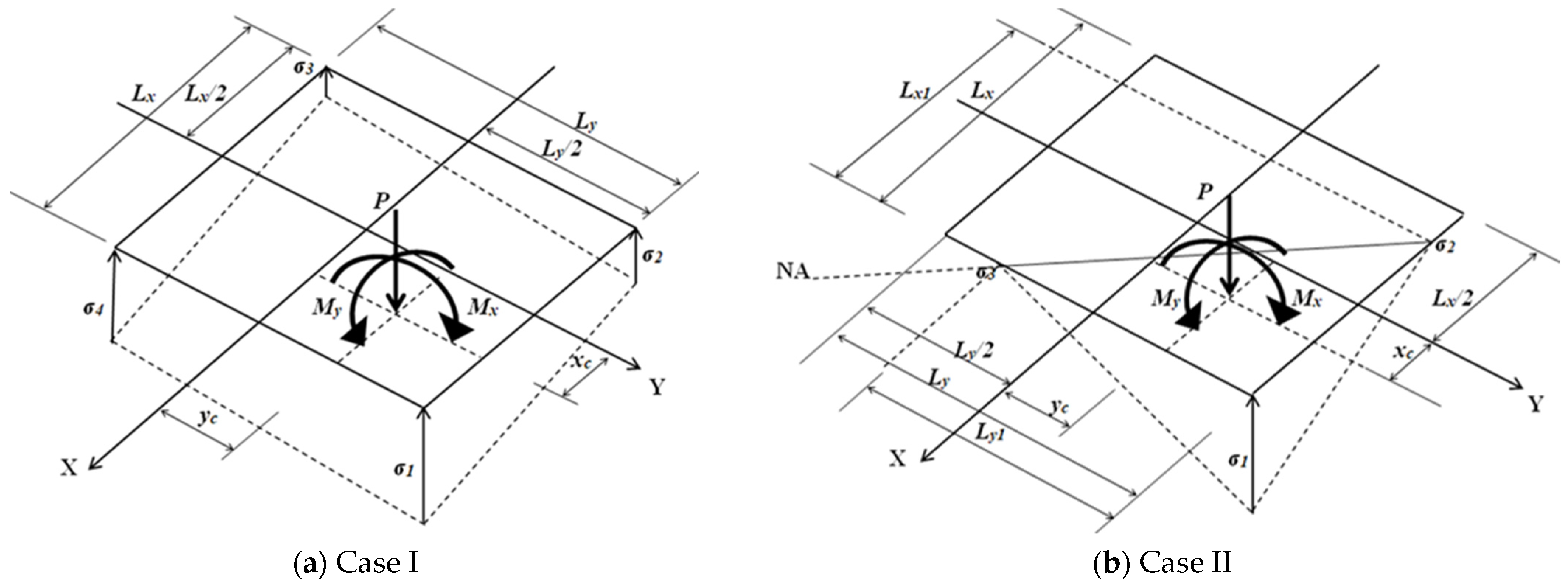
- This paper shows simplified and precise equations for P, Mx, and My in each case, as well as the minimum area and its constraint functions. Furthermore, it shows a significant reduction in the minimum contact area with the ground with respect to the model proposed by the other authors; if the resultant force is outside the central nucleus, this is because the footing is partially supported.
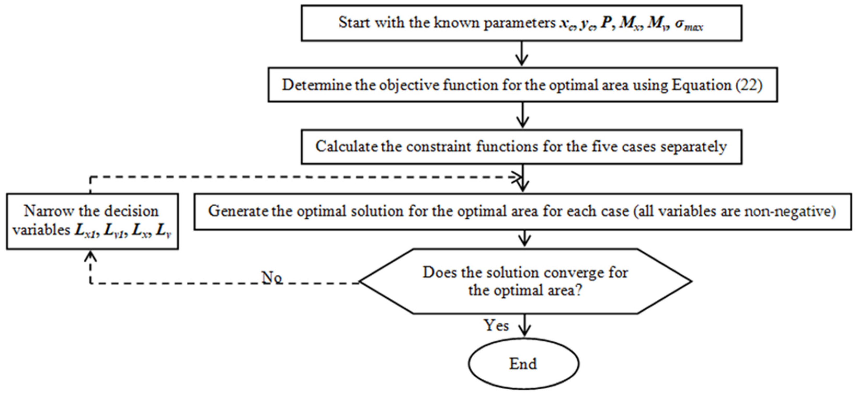
- This model can be used to verify the allowable load capacity of the soil considering maximizing “σmax” (the objective function), the same constraint functions, and the known parameters “Lx” and “Ly”.
- Minimum-cost design for rectangular isolated footings with an eccentric column, assuming that the footing is partially supported.
- Minimum area for rectangular combined footings with eccentric columns, assuming that the footing is partially supported.
Author Contributions
Funding
Institutional Review Board Statement
Informed Consent Statement
Data Availability Statement
Acknowledgments
Conflicts of Interest
Appendix A
| Case | Lx (m) | Ly (m) | Lx1 (m) | Ly1 (m) | σmax-act (kN/m2) | Amin (m2) |
|---|---|---|---|---|---|---|
| Problem 1.A: P = 1200 kN, Mx = 800 kN-m, My = 400 kN-m, xc = 0, and yc = 0 | ||||||
| I | 4.00 | 8.00 | - | - | 75.00 | 32.00 |
| II | No solution available | |||||
| III | 5.36 | 3.13 | 16.86 | 3.13 | 200.00 | 16.76 |
| IV | 1.56 | 10.71 | 1.56 | 33.71 | 200.00 | 16.76 |
| V | 3.01 | 5.00 | 5.46 | 7.58 | 200.00 | 15.04 |
| FS-V | 3.05 | 5.00 | 5.59 | 7.56 | 196.43 | 15.25 |
| Problem 1.B: P = 800 kN, Mx = 800 kN-m, My = 400 kN-m, xc = 0, and yc = 0 | ||||||
| I | 6.00 | 12.00 | - | - | 22.22 | 72.00 |
| II | No solution available | |||||
| III | 3.70 | 4.17 | 6.14 | 4.17 | 200.00 | 15.42 |
| IV | 2.08 | 7.40 | 2.08 | 12.29 | 200.00 | 15.42 |
| V | 2.72 | 5.44 | 3.50 | 7.01 | 200.00 | 14.80 |
| FS-V | 2.75 | 5.45 | 3.57 | 7.02 | 196.06 | 14.99 |
| Problem 1.C: P = 400 kN, Mx = 800 kN-m, My = 400 kN-m, xc = 0, and yc = 0 | ||||||
| I | 12.00 | 24.00 | - | - | 2.78 | 288.00 |
| II | 3.22 | 6.45 | 2.45 | 4.90 | 200.00 | 20.80 |
| III | 4.00 | 5.50 | 4.00 | 3.00 | 200.00 | 22.00 |
| IV | 2.75 | 8.00 | 1.50 | 8.00 | 200.00 | 22.00 |
| V | No solution available | |||||
| FS-II | 3.25 | 6.45 | 2.50 | 4.90 | 195.92 | 20.96 |
| Case | Lx (m) | Ly (m) | Lx1 (m) | Ly1 (m) | σmax-act (kN/m2) | Amin (m2) |
|---|---|---|---|---|---|---|
| Problem 2.A: P = 1200 kN, Mx = 400 kN-m, My = −800 kN-m, xc = Lx/2 − c2/2, and yc = 0 | ||||||
| I | 1.73 | 4.88 | - | - | 200.00 | 8.46 |
| II | No solution available | |||||
| III | No solution available | |||||
| IV | 3.01 | 5.52 | 3.01 | 17.83 | 200.00 | 16.61 |
| V | 2.11 | 4.67 | 4.79 | 16.24 | 200.00 | 9.84 |
| FS-I | 1.75 | 4.95 | - | - | 198.46 | 8.66 |
| Problem 2.B: P = 800 kN, Mx = 400 kN-m, My = −800 kN-m, xc = Lx/2 − c2/2, and yc = 0 | ||||||
| I | 2.40 | 3.22 | - | - | 200.00 | 7.73 |
| II | No solution available | |||||
| III | No solution available | |||||
| IV | 4.65 | 3.45 | 4.65 | 5.42 | 200.00 | 16.04 |
| V | 2.42 | 3.20 | 374.41 | 3.34 | 200.00 | 7.76 |
| FS-I | 2.40 | 3.25 | - | - | 197.24 | 7.80 |
| Problem 2.C: P = 400 kN, Mx = 400 kN-m, My = −800 kN-m, xc = Lx/2 − c2/2, and yc = 0 | ||||||
| I | 4.40 | 6.00 | - | - | 30.30 | 26.40 |
| II | 8.80 | 2.68 | 8.80 | 1.36 | 200.00 | 23.60 |
| III | 4.40 | 2.61 | 5,629,531.75 | 0.91 | 200.00 | 11.47 |
| IV | No solution available | |||||
| V | No solution available | |||||
| FS-III | 4.45 | 2.65 | 134.23 | 0.99 | 187.51 | 11.79 |
| Case | Lx (m) | Ly (m) | Lx1 (m) | Ly1 (m) | σmax-act (kN/m2) | Amin (m2) |
|---|---|---|---|---|---|---|
| Problem 3.A: P = 1200 kN, Mx = −800 kN-m, My = 400 kN-m, xc = 0, and yc = Ly/2 − c1/2 | ||||||
| I | 4.88 | 1.73 | - | - | 200.00 | 8.46 |
| II | No solution available | |||||
| III | 5.52 | 3.01 | 17.83 | 3.01 | 200.00 | 16.61 |
| IV | No solution available | |||||
| V | 4.67 | 2.11 | 16.24 | 4.79 | 200.00 | 9.84 |
| FS-I | 4.95 | 1.75 | - | - | 198.46 | 8.66 |
| Problem 3.B: P = 800 kN, Mx = −800 kN-m, My = 400 kN-m, xc = 0, and yc = Ly/2 − c1/2 | ||||||
| I | 3.22 | 2.40 | - | - | 200.00 | 7.73 |
| II | No solution available | |||||
| III | 3.45 | 4.65 | 5.42 | 4.65 | 200.00 | 16.04 |
| IV | No solution available | |||||
| V | 3.20 | 2.42 | 3.34 | 374.41 | 200.00 | 7.76 |
| FS-I | 3.25 | 2.40 | - | - | 197.24 | 7.80 |
| Problem 3.C: P = 400 kN, Mx = −800 kN-m, My = 400 kN-m, xc = 0, and yc = Ly/2 − c1/2 | ||||||
| I | 6.00 | 4.40 | - | - | 30.30 | 26.40 |
| II | 2.68 | 8.80 | 1.36 | 8.80 | 200.00 | 23.60 |
| III | No solution available | |||||
| IV | 2.61 | 4.40 | 0.91 | 563,951.12 | 200.00 | 11.47 |
| V | No solution available | |||||
| FS-IV | 2.65 | 4.45 | 0.99 | 134.23 | 187.51 | 11.79 |
| Case | Lx (m) | Ly (m) | Lx1 (m) | Ly1 (m) | σmax-act (kN/m2) | Amin (m2) |
|---|---|---|---|---|---|---|
| Problem 4.A: P = 800 kN, Mx = −800 kN-m, My = −700 kN-m, xc = Lx/2 − c2/2, and yc = Ly/2 − c1/2 | ||||||
| I | 2.08 | 2.32 | - | - | 200.00 | 4.82 |
| II | No solution available | |||||
| III | No solution available | |||||
| IV | No solution available | |||||
| V | No solution available | |||||
| FS-I | 2.10 | 2.35 | - | - | 184.03 | 4.94 |
| Problem 4.B: P = 600 kN, Mx = −800 kN-m, My = −700 kN-m, xc = Lx/2 − c2/2, and yc = Ly/2 − c1/2 | ||||||
| I | 2.34 | 2.63 | - | - | 194.86 | 6.16 |
| II | No solution available | |||||
| III | 2.71 | 2.28 | 92.09 | 2.28 | 200.00 | 6.18 |
| IV | 2.04 | 3.04 | 2.04 | 103.32 | 200.00 | 6.18 |
| V | 2.33 | 2.62 | 4.59 | 5.15 | 200.00 | 6.10 |
| FS-V | 2.35 | 2.65 | 4.71 | 2.65 | 188.94 | 6.23 |
| Problem 4.C: P = 400 kN, Mx = −800 kN-m, My = −700 kN-m, xc = Lx/2 − c2/2, and yc = Ly/2 − c1/2 | ||||||
| I | 3.34 | 3.77 | - | - | 2.79 | 12.61 |
| II | No solution available | |||||
| III | 2.93 | 2.95 | 4.17 | 2.95 | 200.00 | 8.66 |
| IV | 2.62 | 3.31 | 2.61 | 4.71 | 200.00 | 8.66 |
| V | 2.76 | 3.12 | 3.27 | 3.69 | 200.00 | 8.61 |
| FS-V | 2.80 | 3.15 | 3.44 | 3.83 | 184.29 | 8.82 |
References
- Coduto, D.P.; Kitch, W.A.; Yeung, M.R. Foundation Design Principles and Practices; Prentice-Hall, Inc.: Hoboken, NJ, USA, 2001. [Google Scholar]
- Cunha, P.R.; Albuquerque, P.J.R. Advance of foundation techniques in Brazil since colonial times. Dyna 2014, 81, 178–187. [Google Scholar] [CrossRef]
- Hassaan, G.A. Optimal design of machinery shallow foundations with sand soils. Int. J. Res. Eng. Technol. 2014, 5, 91–103. Available online: https://es.slideshare.net/slideshow/optimal-design-of-machinery-shallow-foundations-with-clay-soils/58360566 (accessed on 22 April 2024).
- Momeni, E.; Nazir, R.; Armaghani, D.J.; Maizir, H. Application of Artificial Neural Network for Predicting Shaft and Tip Resistances of Concrete Piles. Earth Sci. Res. J. 2015, 19, 85–95. [Google Scholar] [CrossRef]
- Camero, H.E. A novel finite element method for designing floor slabs on grade and pavements with loads at edges. Ing. Investig. 2015, 35, 15–22. [Google Scholar] [CrossRef][Green Version]
- Luévanos-Rojas, A. A comparative study for the design of rectangular and circular isolated footings using new models. Dyna 2016, 83, 149–158. [Google Scholar] [CrossRef]
- Rezaei, H.; Nazir, R.; Momeni, E. Bearing capacity of thin-walled shallow foundations: An experimental and artificial intelligence-based study. J. Zhejiang Univ. Sci. A 2016, 7, 273–285. [Google Scholar] [CrossRef]
- Kassouf, R.; De Carvalho, D.; Rocha-de Albuquerque, P.J. The behavior of a foundation transversally loaded at the top over highly porous and collapsible soil. Dyna 2016, 83, 134–139. [Google Scholar] [CrossRef]
- Luévanos-Rojas, A.; López-Chavarría, S.; Medina-Elizondo, M. Optimal design for rectangular isolated footings using the real soil pressure. Ing. Investig. 2017, 37, 25–33. [Google Scholar] [CrossRef]
- Khatri, V.N.; Debbarma, S.P.; Dutta, R.K.; Mohanty, B. Pressure-settlement behavior of square and rectangular skirted footings resting on sand. Geomech. Eng. 2017, 12, 689–705. [Google Scholar] [CrossRef]
- Munévar-Peña, M.A.; Ramos-Cañón, A.M.; Prada-Sarmiento, L.F. Incorporación de la incertidumbre aleatoria de las propiedades del suelo en la geoestadística. Aplicación al diseño de cimentaciones basado en confiabilidad. Boletín Cienc. Tierra 2018, 44, 38–48. [Google Scholar] [CrossRef]
- Rodrigo-García, J.; Rocha-de Albuquerque, P.J. Model of nonlinear behavior applied to prediction of settlement in deep foundations. Dyna 2018, 85, 171–178. [Google Scholar] [CrossRef]
- Rawat, S.; Mittal, R.K. Optimization of eccentrically loaded reinforced-concrete isolated footings. Pract. Period. Struct. Des. Constr. 2018, 23, 06018002. [Google Scholar] [CrossRef]
- Zhang, W.-X.; Wu, H.; Hwang, H.-J.; Zhang, J.-Y.; Chen, B.; Yi, W.-J. Bearing behavior of reinforced concrete column-isolated footing substructures. Eng. Struct. 2019, 200, 109744. [Google Scholar] [CrossRef]
- Liu, B.; Jiang, X. Consolidation and deformation characteristics of soft rock foundation in a hydrological wetland environment. Earth Sci. Res. J. 2020, 24, 183–190. [Google Scholar] [CrossRef]
- Gnananandarao, T.; Khatri, V.N.; Dutta, R.K. Bearing capacity and settlement prediction of multi-edge skirted footings resting on sand. Ing. Investig. 2020, 40, 9–21. [Google Scholar] [CrossRef]
- Al-Ansari, M.S.; Afzal, M.S. Structural analysis and design of irregular shaped footings subjected to eccentric loading. Eng. Rep. 2021, 3, e12283. [Google Scholar] [CrossRef]
- Al-Abbas, K.A.; Saadoon, S.; Al-Robay, A.A. Experimental study for elastic deformation under isolated footing. Period. Eng. Nat. Sci. 2020, 8, 942–948. [Google Scholar] [CrossRef]
- López-Machado, N.A.; Perez, G.; Castro, C.; Perez, J.C.V.; López-Machado, L.J.; Alviar-Malabet, J.D.; Romero-Romero, C.A.; Guerrero-Cuasapaz, D.P.; Montesinos-Machado, V.V. A Structural Design Comparison Between Two Reinforced Concrete Regular 6-Level Buildings using Soil-Structure Interaction in Linear Range. Ing. Investig. 2022, 42, e86819. [Google Scholar] [CrossRef]
- Komolafe, O.O.; Balogun, I.O.; Abiodun, U.O. Comparison of square and circular isolated pad foundations in cohesionless soils. Arid Zone J. Eng. Technol. Environ. 2023, 17, 197–210. Available online: https://www.ajol.info/index.php/azojete/article/view/243597 (accessed on 22 April 2024).
- Ekbote, A.G.; Nainegali, L. Study on Closely Spaced Asymmetric Footings Embedded in a Reinforced Soil Medium. Ing. Investig. 2023, 43, e101082. [Google Scholar] [CrossRef]
- Solorzano, G.; Plevris, V. Optimum Design of RC Footings with Genetic Algorithms According to ACI 318-19. Buildings 2022, 10, 110. [Google Scholar] [CrossRef]
- ACI 318-19; Building Code Requirements for Structural Concrete and Commentary. American Concrete Institute: Farmington Hills, MI, USA, 2019.
- Waheed, J.; Azam, R.; Riaz, M.R.; Shakeel, M.; Mohamed, A.; Ali, E. Metaheuristic-Based Practical Tool for Optimal Design of Reinforced Concrete Isolated Footings: Development and Application for Parametric Investigation. Buildings 2022, 12, 471. [Google Scholar] [CrossRef]
- Helis, R.; Mansouri, T.; Abbeche, K. Behavior of a Circular Footing resting on Sand Reinforced with Geogrid and Grid Anchors. Eng. Technol. Appl. Sci. Res. 2023, 13, 10165–10169. [Google Scholar] [CrossRef]
- Vela-Moreno, V.B.; Luévanos-Rojas, A.; López-Chavarría, S.; Medina-Elizondo, M.; Sandoval-Rivas, R.; Martínez-Aguilar, C. Optimal area for rectangular isolated footings considering that contact surface works partially to compression. Struct. Eng. Mech. 2022, 84, 561–573. [Google Scholar] [CrossRef]
- Luévanos-Rojas, A. Minimum cost design for rectangular isolated footings taking into account that the column is located in any part of the footing. Buildings 2023, 13, 2269. [Google Scholar] [CrossRef]

| Case | Constraint Functions |
|---|---|
| I | Equations (2)–(5) and 0 ≤ σ1, σ2, σ3, σ4 ≤ σmax |
| II | Equations (10)–(12), Lx ≥ Lx1 and Ly ≥ Ly1 |
| III | Equations (13)–(15), Lx ≤ Lx1 and Ly ≥ Ly1 |
| IV | Equations (16)–(18), Lx ≥ Lx1 and Ly ≤ Ly1 |
| V | Equations (19)–(21), Lx ≤ Lx1 and Ly ≤ Ly1 |
| Case | Coordinates | σZ | |
|---|---|---|---|
| x | y | ||
| II | Lx/2 | Ly/2 | σmax |
| Lx/2 | Ly/2 − Ly1 | 0 | |
| Lx/2 − Lx1 | Ly/2 | 0 | |
| III | Lx/2 | Ly/2 | σmax |
| −Lx/2 | Ly/2 − Ly2 (Ly2 = Ly1(Lx1 − Lx)/Lx1) | 0 | |
| Lx/2 | Ly/2 − Ly1 | 0 | |
| IV | Lx/2 | Ly/2 | σmax |
| Lx/2 − Lx1 | Ly/2 | 0 | |
| Lx/2 − Lx2 (Lx2 = Lx1(Ly1 − Ly)/Ly1) | −Ly/2 | 0 | |
| V | Lx/2 | Ly/2 | σmax |
| −Lx/2 | Ly/2 − Ly2 (Ly2 = Ly1(Lx1 − Lx)/Lx1) | 0 | |
| Lx/2 − Lx2 (Lx2 = Lx1(Ly1 − Ly)/Ly1) | −Ly/2 | 0 | |
| Case | Lx (m) | Ly (m) | Lx1 (m) | Ly1 (m) | σmax-act (kN/m2) | Amin (m2) |
|---|---|---|---|---|---|---|
| Problem 1.1: P = 1000 kN, Mx = 225 kN-m, My = 150 kN-m, xc = 0, and yc = 0 | ||||||
| I | 2.52 | 3.78 | - | - | 180.00 | 9.52 |
| II | No solution available | |||||
| III | 9.77 | 1.24 | 110.85 | 1.24 | 180.00 | 12.15 |
| IV | 0.83 | 14.65 | 0.83 | 166.28 | 180.00 | 12.15 |
| V | 4.38 | 2.19 | 26.03 | 3.33 | 180.00 | 9.60 |
| FS-I | 2.55 | 3.80 | - | - | 176.29 | 9.69 |
| Problem 1.2: P = 850 kN, Mx = 225 kN-m, My = 150 kN-m, xc = 0, and yc = 0 | ||||||
| I | 2.43 | 3.64 | - | - | 180.00 | 8.84 |
| II | No solution available | |||||
| III | 7.63 | 1.41 | 58.74 | 1.41 | 180.00 | 10.79 |
| IV | 0.94 | 11.45 | 0.94 | 88.11 | 180.00 | 10.79 |
| V | 2.43 | 3.64 | 5.22 | 7.83 | 180.00 | 8.83 |
| FS-V | 2.45 | 3.65 | 6.58 | 9.70 | 156.63 | 8.94 |
| Problem 1.3: P = 750 kN, Mx = 225 kN-m, My = 150 kN-m, xc = 0, and yc = 0 | ||||||
| I | 2.40 | 3.60 | - | - | 173.61 | 8.64 |
| II | No solution available | |||||
| III | 6.41 | 1.55 | 37.37 | 1.55 | 180.00 | 9.94 |
| IV | 1.03 | 9.62 | 1.03 | 56.05 | 180.00 | 9.94 |
| V | 2.37 | 3.55 | 4.70 | 7.05 | 180.00 | 8.39 |
| FS-V | 2.40 | 3.55 | 4.82 | 7.03 | 176.68 | 8.52 |
| Problem 1.4: P = 600 kN, Mx = 225 kN-m, My = 150 kN-m, xc = 0, and yc = 0 | ||||||
| I | 3.00 | 4.50 | - | - | 88.89 | 13.50 |
| II | No solution available | |||||
| III | 4.87 | 1.81 | 18.11 | 1.81 | 180.00 | 8.83 |
| IV | 1.21 | 7.30 | 1.21 | 27.17 | 180.00 | 8.83 |
| V | 2.28 | 3.42 | 3.97 | 5.96 | 180.00 | 7.78 |
| FS-V | 2.30 | 3.45 | 4.03 | 6.05 | 175.30 | 7.93 |
| Case | Lx (m) | Ly (m) | Lx1 (m) | Ly1 (m) | σmax-act (kN/m2) | Amin (m2) |
|---|---|---|---|---|---|---|
| Problem 4.1: P = 750 kN, Mx = −750 kN-m, My = −600 kN-m, xc = Lx/2 − c2/2, and yc = Ly/2 − c1/2 | ||||||
| I | 1.96 | 2.36 | - | - | 180.00 | 4.63 |
| II | No solution available | |||||
| III | No solution available | |||||
| IV | No solution available | |||||
| V | No solution available | |||||
| FS-I | 2.00 | 2.35 | - | - | 169.76 | 4.70 |
| Problem 4.2: P = 605 kN, Mx = −750 kN-m, My = −600 kN-m, xc = Lx/2 − c2/2, and yc = Ly/2 − c1/2 | ||||||
| I | 2.15 | 2.59 | - | - | 180.00 | 5.57 |
| II | No solution available | |||||
| III | No solution available | |||||
| IV | No solution available | |||||
| V | No solution available | |||||
| FS-I | 2.15 | 2.60 | - | - | 178.37 | 5.59 |
| Problem 4.3: P = 450 kN, Mx = −750 kN-m, My = −600 kN-m, xc = Lx/2 − c2/2, and yc = Ly/2 − c1/2 | ||||||
| I | 2.63 | 3.20 | - | - | 107.00 | 8.41 |
| II | No solution available | |||||
| III | 2.71 | 2.61 | 8.20 | 2.61 | 180.00 | 7.09 |
| IV | 2.15 | 3.30 | 2.15 | 9.98 | 180.00 | 7.09 |
| V | 2.40 | 2.92 | 3.67 | 4.46 | 180.00 | 6.99 |
| FS-V | 2.40 | 2.95 | 3.66 | 4.70 | 173.04 | 7.08 |
| Problem 4.4: P = 300 kN, Mx = −750 kN-m, My = −600 kN-m, xc = Lx/2 − c2/2, and yc = Ly/2 − c1/2 | ||||||
| I | 3.77 | 4.63 | - | - | 34.37 | 17.46 |
| II | 2.91 | 3.58 | 2.85 | 3.50 | 180.00 | 10.42 |
| III | 2.93 | 3.55 | 2.93 | 3.41 | 180.00 | 10.42 |
| IV | 2.89 | 3.60 | 2.78 | 3.60 | 180.00 | 10.42 |
| V | No solution available | |||||
| FS-II | 2.90 | 3.60 | 2.80 | 3.60 | 178.57 | 10.44 |
Disclaimer/Publisher’s Note: The statements, opinions and data contained in all publications are solely those of the individual author(s) and contributor(s) and not of MDPI and/or the editor(s). MDPI and/or the editor(s) disclaim responsibility for any injury to people or property resulting from any ideas, methods, instructions or products referred to in the content. |
© 2024 by the authors. Licensee MDPI, Basel, Switzerland. This article is an open access article distributed under the terms and conditions of the Creative Commons Attribution (CC BY) license (https://creativecommons.org/licenses/by/4.0/).
Share and Cite
Moreno-Landeros, V.M.; Luévanos-Rojas, A.; Santiago-Hurtado, G.; López-León, L.D.; Diaz-Gurrola, E.R. Optimal Area for a Rectangular Isolated Footing with an Eccentric Column and Partial Ground Compression. Appl. Sci. 2024, 14, 6453. https://doi.org/10.3390/app14156453
Moreno-Landeros VM, Luévanos-Rojas A, Santiago-Hurtado G, López-León LD, Diaz-Gurrola ER. Optimal Area for a Rectangular Isolated Footing with an Eccentric Column and Partial Ground Compression. Applied Sciences. 2024; 14(15):6453. https://doi.org/10.3390/app14156453
Chicago/Turabian StyleMoreno-Landeros, Victor Manuel, Arnulfo Luévanos-Rojas, Griselda Santiago-Hurtado, Luis Daimir López-León, and Eyran Roberto Diaz-Gurrola. 2024. "Optimal Area for a Rectangular Isolated Footing with an Eccentric Column and Partial Ground Compression" Applied Sciences 14, no. 15: 6453. https://doi.org/10.3390/app14156453
APA StyleMoreno-Landeros, V. M., Luévanos-Rojas, A., Santiago-Hurtado, G., López-León, L. D., & Diaz-Gurrola, E. R. (2024). Optimal Area for a Rectangular Isolated Footing with an Eccentric Column and Partial Ground Compression. Applied Sciences, 14(15), 6453. https://doi.org/10.3390/app14156453


