Article

Tooth Surface Deviation Analysis for Continuous Generation Grinding of Internal Gears

1
Electromechanical College, Henan University of Science and Technology, Luoyang 471000, China
2
Longmen Laboratory, Luoyang 471000, China
3
State Key Laboratory of Superabrasives, Zhengzhou 450007, China
*
Author to whom correspondence should be addressed.
Appl. Sci. 2024, 14(15), 6551; https://doi.org/10.3390/app14156551 (registering DOI)
Submission received: 1 July 2024 / Revised: 23 July 2024 / Accepted: 24 July 2024 / Published: 26 July 2024

Abstract

:
In order to resolve the issues of low efficiency and poor precision in the traditional finishing process of hardened internal gears, a method is proposed for calculating the profile curves of a drum-shaped grinding tool suitable for mass finishing of hardened internal gears. Additionally, the impact of drum-shaped grinding tool installation errors on the tooth surface deviation of internal gears is analyzed. Firstly, the processing principle for the generation grinding of internal gears by the drum-shaped grinding tool is introduced. Based on differential geometry, meshing theory, and two-degree-of-freedom enveloping method, a mathematical model is developed for the generation grinding of internal gears. Profile curves of the drum-shaped grinding tool are obtained by solving the meshing equation between the drum-shaped grinding tool and the internal gear. Then, the tooth surface equation for the internal gear is derived in the presence of drum-shaped grinding tool installation errors. By discretizing the error tooth surface of the internal gear, the average normal deviation of the tooth surface is calculated. In the end, the distribution of normal deviation on the tooth surface of the internal gear with different drum-shaped grinding tool installation errors is acquired, and the influence of four kinds of installation errors on the tooth surface of the internal gear is analyzed. The sensitive direction is identified for drum-shaped grinding tool installation errors on the tooth surface of the internal gear. Consequently, this research provides a calculation method for the drum-shaped grinding tool fit for high-precision and high-efficiency finishing of mass-produced hardened internal gear and offers a reference for correcting deviation in the tooth surface of internal gear with installation errors of the drum-shaped grinding tool.

1. Introduction

Planetary gearboxes with advantages such as smooth transmission, compact structure, and high load-bearing capacity are key components of the high-speed hub motor drive systems in new energy vehicles. High-precision internal gear can effectively reduce the noise and vibration of the gearbox and enhance its dynamic performance [1]. Along with the continuous increase in rotation speed of the motor, the higher machining precision of the internal gear is necessary to meet with the requirement of dynamic performance demands.
Currently, grinding is the main finishing method to eliminate tooth surface heat treatment deformation, improve surface roughness, and enhance gear precision [2,3], it has garnered significant attention from many scholars in recent years [4,5,6]. Tooth-surface grinding methods can be divided into forming grinding and generation grinding [7]. For small- and medium-module external gears, high-precision and high-efficiency generation grinding processes have been widely applied [8,9]. In the case of internal gears, due to the limitation of their spatial structure, forming grinding is mainly used for precision machining [10]. However, the indexing error between gear teeth and noncutting return in the process of grinding results in poor precision and low efficiency. Therefore, forming is unsuitable for the mass production of internal gears utilized in the gear reducers of automobiles.
Generating machining methods for internal gears include gear shaping, gear hobbing, and gear skiving. Gear shaper cutters machine internal gears through reciprocating motion, but their efficiency is low due to the noncutting return. Taku et al. [11] were the first to propose the method of hobbing internal gears and calculated the parameters for the hob. Guo et al. [12,13] analyzed the impact of setup errors of gear-skiving cutters on machining accuracy and improved the cutting performance of the tool. Tsai [14,15] proposed and optimized a mathematical modeling method for gear skiving based on discrete enveloping, and the skiving cutter was analyzed and designed. Trong [16] used a rack as a simplified skiving cutter and proposed a design method for a conical skiving cutter that allows for a predetermined grinding allowance. Shih et al. [17] solved an error-free skiving cutter profile through reverse enveloping, used B-splines to fit the cutter surface, and manufactured the error-free skiving cutter on a multi-axis CNC grinding machine based on the fitted surface. Guo et al. [18,19,20,21] proposed and improved a multi-edge skiving cutter that can homogenize the cutting load; although the theoretical cutting efficiency of the multi-edge cutter is higher, it has not been widely applied due to the difficulty in manufacturing this tool. Osafune et al. [22] proposed an evaluation method of a continuous varying skiving cutter suitable for internal gears. Uriu et al. [23] investigated the effectiveness of the gear skiving axis intersection angle by calculating the cutter parameters. Ren et al. [24] proposed a mathematical model based on Z-mapping to calculate the gear tooth surface in the presence of eccentric errors. Jia et al. [25] introduced a mathematical model of gear skiving based on discrete envelopes, researched the influence of tool motion on machining accuracy, and performed simulation experiments to validate the model. Li et al. [26,27] developed a gear skiving cutter based on free-form surface and analyzed the impact of machining parameters on cutting force. Chen et al. [28,29] proposed a design method for gear skiving tools with on theoretical machining errors and introduced the grinding principle. Although gear skiving has been widely used, it is not suitable for machining hardened internal gears due to the tool wear.
For finishing hardened internal gears, Yanse et al. [30] proposed a generation grinding method for mass production and verified this by experiment. Chen et al. [31] proposed a method for machining internal gears by using a worm cutter, but it is limited by the manufacturing of the tool. Due to the increasing demand for hardened internal gears, it is crucial to develop a method suitable for mass-production precision finishing of internal gears.
In summary, although research on the generation grinding of internal gears has made some progress, there are many challenges in tool design, manufacturing, and process equipment, which has resulted in a lack of general applications to harden internal gears. The demand for a large quantity of high-precision hardened internal gears required by the drive systems of new energy vehicles’ hub motors can be met through the use of a drum-shaped grinding tool for finishing the internal gear. Therefore, the meshing calculation of the drum-shaped grinding tool for grinding the internal helical gear is presented firstly in this work. The coordinate relationship between the drum-shaped grinding tool and internal helical gear is established, and the two-degree-of-freedom meshing equation is derived to obtain the profiles of the drum-shaped grinding tool. Then, based on the generation grinding process of the internal helical gear, the surface deviation of the internal helical gear is analyzed due to the installation errors of the drum-shaped grinding tool. The research results are significant for improving the finishing precision of the internal helical gear and correcting the error tooth surface.

2. Calculation of the Surface of the Drum-Shaped Grinding Tool

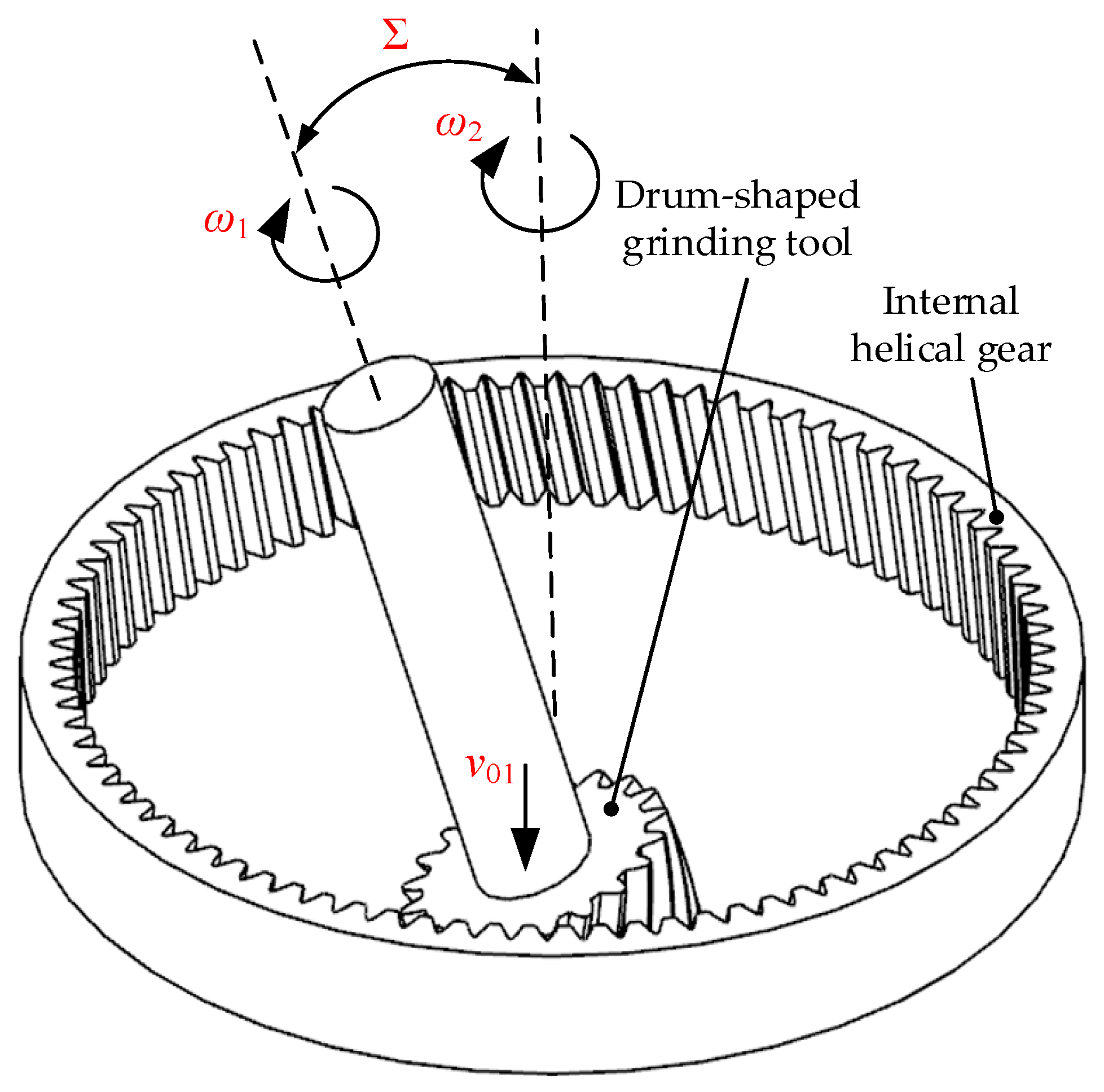
2.1. Tooth Surface of the Internal Helical Gear

The transverse profiles of the internal helical gear and a single tooth are shown in Figure 1.
rb is the base circle radius of the internal helical gear, rf is the dedendum circle radius of the internal helical gear, u means the involute expansion angle, and σ0 means the angle between the line connecting the starting position of the involute and the origin with the x2 axis.
The transverse profile equation of the internal helical gear can be described as follows:
r 2 = r b cos ( u + σ 0 ) + r b u sin ( u + σ 0 ) ± r b sin ( u + σ 0 ) r b u cos ( u + σ 0 ) 0 1
where the upper parts of the symbols ± and in r2 denote the transverse profile of the left tooth surface, and the lower parts denote the transverse profile of the right tooth surface.
The tooth surface R2 of the internal gear is obtained by rotating and stretching the transverse profile along the helical angle, which can be represented as:
R 2 = M 2 t r 2
M 2 t = cos θ 2 ± sin θ 2 0 0 sin θ 2 cos θ 2 0 0 0 0 1 - P 2 θ 2 0 0 0 1
where the upper parts of the symbols ± and in M2t mean the right-hand helical tooth surface, and the lower parts mean the left-hand tooth surface, θ2 is the rotational angle of the transverse profile of internal helical gear, and P2 is the helical parameter of the internal helical gear, which can be obtained as:
P 2 = Z 2 m n 2 sin β 2
where Z2 expresses the tooth number of the internal helical gear, mn represents the module of the internal helical gear, and β2 means the helical angle of the internal helical gear. The tooth surface normal vector n2 of the internal helical gear can be expressed as:
n 2 = R 2 ( u , θ 2 ) u × R 2 ( u , θ 2 ) θ 2
To calculate more accurately the profile curves of the drum-shaped grinding tool, the tooth surface of the internal helical gear is discretized by dividing into nine columns and five rows in the tooth length and tooth height directions, respectively, as described in Figure 2.

2.2. Two-Degree-of-Freedom Meshing Equation

To obtain the correct tooth surface of the internal helical gear ground by the drum-shaped grinding tool, two independent motions are necessarily required, which are the generation motion, where the drum-shaped grinding tool and the internal helical gear rotate around their respective axes according to the transmission ratio, and the feed motion, where the drum-shaped grinding tool moves along the axial direction of the internal helical gear. The tooth height profile and width profile of the internal helical gear are obtained through the generating motion and the axial feed motion, respectively. The whole process of generation grinding of the internal helical gear with the drum-shaped grinding tool is completed by the combination of these two motions. Figure 3 shows the model for grinding the internal helical gear using the drum-shaped grinding tool.
Interference between the grinding tool and the internal helical gear due to the presence of shaft angle can be avoided by using the drum-shaped grinding tool. The diameter of the drum-shaped grinding tool gradually increases from both the upper and lower transverse faces towards the middle. Therefore, the transverse face profiles of the drum-shaped grinding tool are different and need to be calculated separately. The coordinate system between the internal helical gear and the drum-shaped grinding tool can be established, as illustrated in Figure 4.
As shown in Figure 4, Sw(Ow-xwywzw) represents the coordinate system at the transverse face of the drum-shaped grinding tool, and it can be moved along the axial direction, and Sg(Og-xgygzg) represents the fixed coordinate system. S1(O1-x1y1z1) and S2(O2-x2y2z2) rotate with the drum-shaped grinding tool and the internal helical gear, respectively. At the initial, the coordinate system S1 coincides with Sw, and S2 coincides with Sg, b′ is the tooth width at the transverse face of the drum-shaped tool, and a is the center distance from the drum-shaped grinding tool to the internal helical gear. z1 and z2 coincide with the rotational axes of the drum-shaped grinding tool and the internal helical gear, respectively, and the angle between the two axes is Σ. The drum-shaped grinding tool rotates around the z1 axis with angular velocity ω1, while the internal helical gear rotates around the z2 axis with angular velocity ω2 and moves along the z2 axis with velocity v02 (in actual processing, this motion is performed by the drum-shaped grinding tool). Δ means the horizontal distance from S1 to S2, which can be obtained as:
Δ = b sin
λ denotes the rotation angle of the internal helical gear at different transverse faces meshing positions, which can be acquired as follows:
λ = arctan Δ a
The number of degree-of-freedom in the spatial meshing motion refers to how many motion parameters are independent. There are three parameters, ω1, ω2, and v02, in the process of generation grinding of the internal helical gear by the drum-shaped grinding tool. Due to the existence of a certain transmission relationship between the drum-shaped grinding tool and the internal helical gear, when ω1 is determined, ω2 is also determined (or when ω2 is determined, ω1 is also determined). Therefore, two motion parameters are independent of each other and are called two-degree-of-freedom meshing.
The transmission relationship between the drum-shaped grinding tool and the internal helical gear can be expressed as:
ω 1 = Z 2 Z 1 ω 2 + v 02 P 2
where Z1 expresses the tooth number of the drum-shaped grinding tool.
The relative velocity between the drum-shaped grinding tool and the internal helical gear at different transverse faces meshing positions can be described as follows:
v 1 = ( ω 1 + ω 2 cos ) ( y + a sin λ ) ω 2 ( z b cos ) sin ω 1 x ω 2 ( x + a cos λ ) cos ω 2 ( x + a cos λ ) sin v 2 = v 02 P 2 ( z b cos ) sin ( y + a sin λ ) cos ( x + a cos λ ) cos v 02 P 2 sin ( x + a cos λ ) cos v 02 P 2 cos
x y z 1 = M w g M g 2 R 2
M w g = 1 0 0 a cos λ cos sin λ cos cos λ sin a sin λ sin sin λ sin cos λ cos b cos 0 0 0 1
M g 2 = cos φ 2 sin φ 2 0 0 sin φ 2 cos φ 2 0 0 0 0 1 L 2 0 0 0 1
where φ2 means the rotational angle of the internal helical gear during the grinding process, L2 is the distance of the internal helical gear moving along the axial direction.
The meshing equation of the drum-shaped grinding tool and the internal helical gear at different transverse faces meshing positions can be represented as:
v 1 · n 2 = 0 v 2 · n 2 = 0
A series of meshing points at different transverse faces of the drum-shaped grinding tool can be obtained by traversing the points on the tooth surface of the internal helical gear.

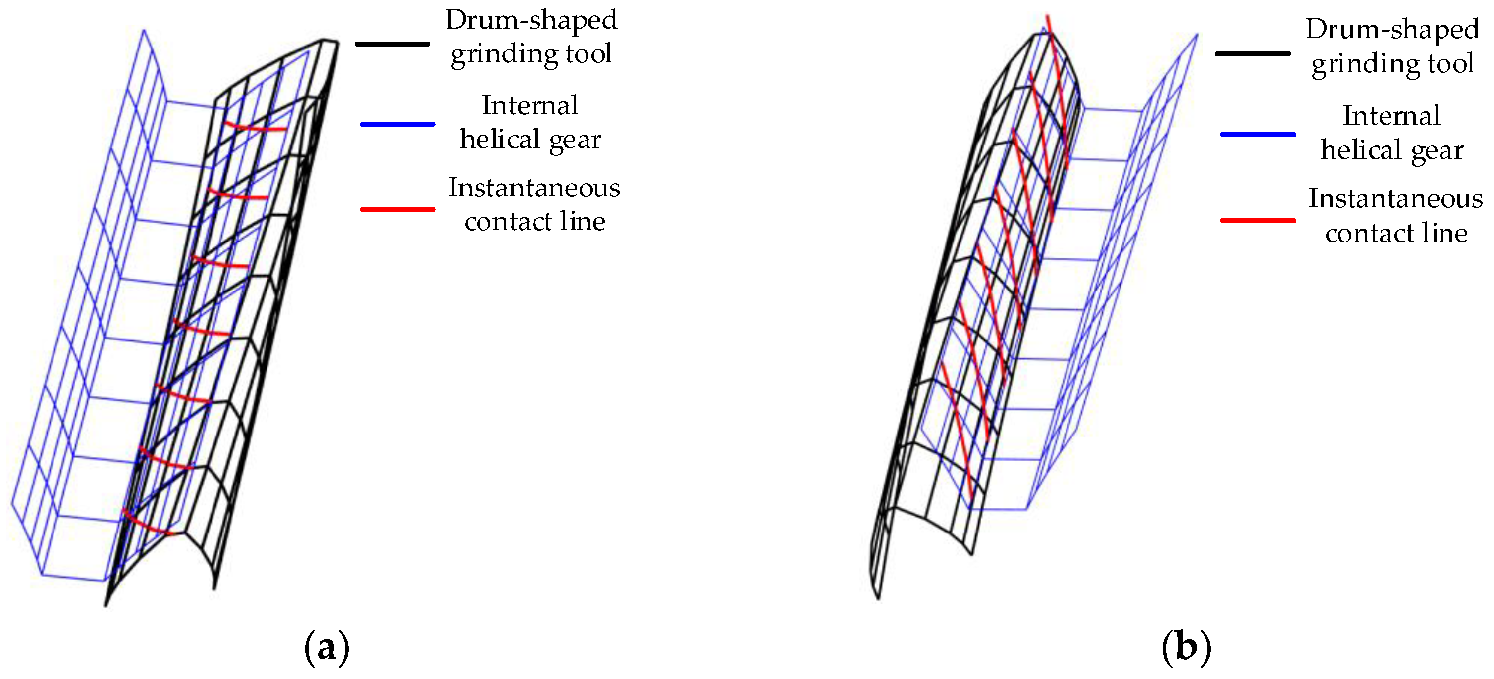
2.3. Calculation of the Transverse Face Profile of the Drum-Shaped Grinding Tool

The instantaneous contact lines Rs at the different transverse faces of the drum-shaped grinding tool are obtained by connecting the meshing points obtained from solving the meshing equation. The instantaneous contact lines are transformed into the coordinate system S1 of the drum-shaped grinding tool, which is given as:
R s 1 = M 1 w R s
M 1 w = cos φ 1 sin φ 1 0 0 sin φ 1 cos φ 1 0 0 0 0 1 0 0 0 0 1
where φ1 means the rotation angle of the drum-shaped grinding tool.
The different transverse faces profile curves R1 of the drum-shaped grinding tool are acquired by rotating and projecting   R s 1 , which can be represented as:
R 1 = M 1 s R s 1
M 1 s = cos δ sin δ 0 0 sin δ cos δ 0 0 0 0 1 0 0 0 0 1
where δ means the rotation angle of the instantaneous contact lines onto the different transverse faces of the drum-shaped grinding tool, which can be expressed as:
δ = Z 2 Z 1 ( λ + b cos P 2 )
Taking the parameters listed in Table 1 as an example, the tooth surface of the drum-shaped grinding tool and internal helical gear are calculated. Figure 5 shows the calculation results of the tooth surfaces of the drum-shaped grinding tool.
The three-dimensional models of the drum-shaped grinding tool and the internal helical gear are created by importing the obtained points into UG and are assembled according to the preset center distance and shaft angle, as shown in Figure 6.

3. Establishment of the Installation Error Model for the Drum-Shaped Grinding Tool

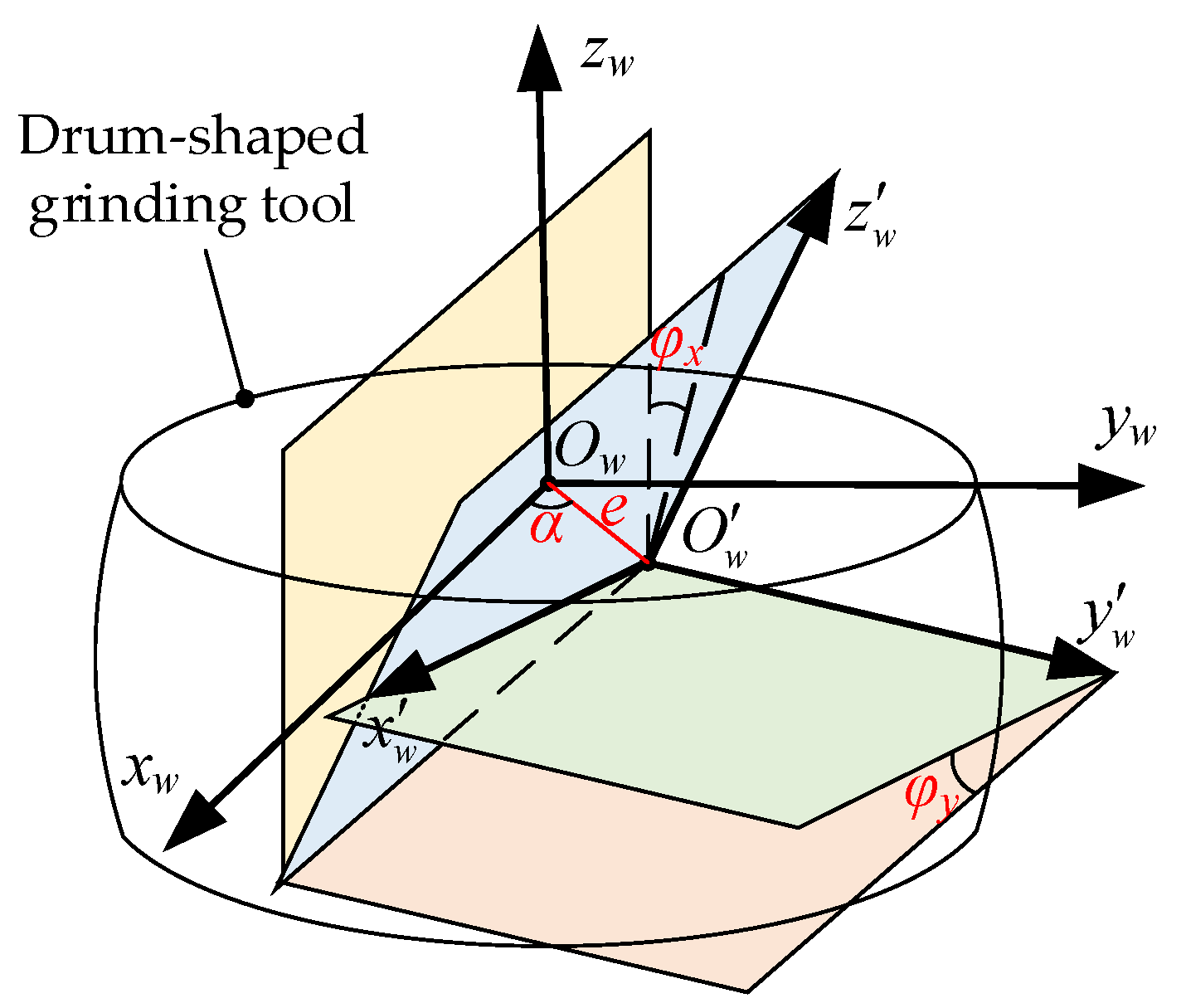
3.1. Analysis of Drum-Shaped Grinding Tool Installation Error

The drum-shaped grinding tool and the internal helical gear moved according to a determined meshing relationship, allowing the whole tooth surface of the internal helical gear to be formed. In the absence of error, the groundtooth surface of the internal helical gear precisely corresponds to the theoretical tooth surface. However, in the actual grinding process, the meshing relationship between the drum-shaped grinding tool and the internal helical gear is changed due to factors such as drum-shaped grinding tool installation errors, force deformation, and thermal deformation. As a result, the actual groundtooth surface of the internal helical gear will deviate to varying degrees from its theoretical tooth surface.
Tooth surface deviations resulting from drum-shaped grinding tool wear, force deformation, and thermal deformation are independent factors. In contrast, drum-shaped grinding tool installation errors are heavily influenced by the processing system. Therefore, analyzing the impact of the drum-shaped grinding tool installation errors on tooth surface deviations is of significant importance. The model of the drum-shaped grinding tool installation error is depicted in Figure 7.
As shown in Figure 7, Sw(Ow-xwywzw) represents the coordinate system of the theoretical position of the drum-shaped grinding tool, S′w(O′w-x′wy′wz′w) represents the coordinate system of the drum-shaped grinding tool in the presence of installation error, e is the eccentricity, α is the eccentric angle, φx denotes the perpendicularity error angle around the xw axis, and φy denotes the perpendicularity error angle around the yw axis.

3.2. Internal Helical Gear Tooth Surface Equation Derived by the Drum-Shaped Grinding Tool

The ground tooth surface of the internal helical gear can be obtained based on the conjugate motion relationship between the drum-shaped grinding tool and the internal helical gear. The internal helical gear tooth surface without drum-shaped grinding tool installation errors can be determined as:
R 2 = M 2 g M g w M w 1 R 1
M 2 g = M g 2 1 M g w = M w g 1 M w 1 = M 1 w 1
where R 1 means the tooth surface of the drum-shaped grinding tool, R 2 means the tooth surface of the internal helical gear in the absence of drum-shaped grinding tool installation errors.
The tooth surface of internal helical gear with drum-shaped grinding tool installation errors can be determined as:
R 2 e = M 2 g M g w e M w 1 R 1
where R 2 e means the tooth surface of internal helical gear with drum-shaped grinding tool installation errors, and M gw e represents the error matrix, which can be obtained as follows:
M g w e = M g w 1 0 0 e cos α 0 1 0 e sin α 0 0 1 0 0 0 0 1 1 0 0 0 0 cos φ x sin φ x 0 0 sin φ x cos φ x 0 0 0 0 1 cos φ y 0 sin φ y 0 0 1 0 0 sin φ y 0 cos φ y 0 0 0 0 1

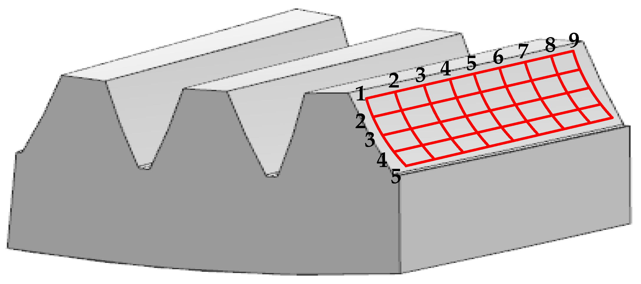
3.3. Deviation Calculation of Internal Helical Gear Tooth Surface

According to the surface equation of the internal helical gear in the absence of drum-shaped grinding tool installation errors, and by discrete tooth surface for calculating the coordinates of tooth surface points, the radial vector rt(i,j) (i = 1–5, j = 1–9) and the normal nt(i,j) of the theoretical tooth surface grid points can be obtained. The same method can be used to obtain the radial vector re(i,j) of the error tooth surface grind points of the internal helical gear in the presence of drum-shaped grinding tool installation errors. Tooth surface normal deviation refers to the distance by which the tooth surface deviates from the theoretical value in the normal direction which can be determined as follows:
K ( i , j ) h = ( r t ( i , j ) r e ( i , j ) ) · n t ( i , j )
The degree of deviation between the error tooth surface and the theoretical tooth surface of the internal helical gear is measured by calculating the average normal deviation value K of the tooth surface, which can be expressed as:
K = Σ i = 1 , j = 1 i = 5 , j = 9 K ( i , j ) h

4. Analysis of the Impact of Drum-Shaped Grinding Tool Installation Errors on Internal Helical Gear Tooth Surface Deviation

The impact of drum-shaped grinding tool installation errors on the distribution of the tooth surface deviation of the internal helical gear is analyzed, based on the parameters of the drum-shaped grinding tool and the internal helical gear provided in Table 1, and the installation errors of the drum-shaped grinding tool detailed in Table 2.
Taking the left tooth surface as an example, the distribution of deviation was researched.
As shown in Figure 8, the distribution of normal deviation of the tooth surface of the internal helical gear involving error A is presented.
From a numerical point of view, it can be seen in Figure 8 that the maximum normal deviation of the tooth surface caused by error A occurs at the tooth dedendum on the upper transverse face and the tooth addendum on the lower transverse face. At the tooth addendum, the normal deviation decreases from the upper transverse face to the lower transverse face and then increases, while at the tooth dedendum, it gradually decreases. The normal deviation varies significantly along both the tooth height and width directions.
As shown in Figure 9, the distribution of normal deviation of the tooth surface of the internal helical gear involving error B is presented.
From Figure 9, it can be observed that the maximum normal deviation of the tooth surface caused by error B occurs at the tooth addendum on both the upper and lower transverse faces. At both the addendum and the tooth dedendum, the normal deviation decreases from the upper transverse face to the lower transverse face and then increases. Thus, normal deviation varies significantly along both the tooth height and width directions.
As shown in Figure 10, the distribution of normal deviation of the tooth surface of the internal helical gear involving error C is presented.
From the numerical result in Figure 10, it can be seen that the maximum normal deviation of the tooth surface caused by error C occurs at the tooth dedendum on both the upper and lower transverse faces. At the tooth addendum, the normal deviation gradually increases from the upper transverse face to the lower transverse face, while at the tooth dedendum, it first decreases and then increases. The variation of the normal deviation along the tooth height direction exceeds that along the tooth width direction.
As shown in Figure 11, the distribution of normal deviation of the tooth surface of the internal helical gear involving error D is presented.
It can be seen in Figure 11 that the maximum normal deviation of the tooth surface caused by error D occurs at the tooth addendum on both the upper and lower transverse faces. At the tooth addendum, the normal deviation decreases from the upper transverse face to the lower transverse face and then increases, while at the tooth dedendum, there is a periodic change, with a decrease followed by an increase. The normal deviation varies significantly along both the tooth height and width directions.
Five cases with eccentricity e values of 0.05 mm, 0.1 mm, 0.2 mm, 0.3 mm, and 0.5 mm were investigated to analyze the variation trend of the average normal deviation of the tooth surface with respect to the eccentric angle, as depicted in Figure 12.
In Figure 12, it can be observed that the average normal deviation of the tooth surface exhibits periodic variations when the eccentric angle changes from −180° to 180°. The normal deviation of the tooth surface reaches its maximum when the eccentric angle approaches −60° and 120°, which is the sensitive direction of eccentric error. The normal deviation of the tooth surface reaches its minimum when the eccentric angle approaches −150° and 30°, which is the insensitive direction of the eccentric error.
Further investigation was conducted on the variation trend of the average normal deviation of the tooth surface with respect to eccentricity. Four cases were investigated with eccentric angle α values of 0°, 30°, 75°, and 120°, as shown in Figure 13.
It is revealed in Figure 13 that the average normal deviation of the tooth surface increases linearly with the increase in eccentricity when the eccentric angle is determined.
Figure 14 shows the variation of the average normal deviation of the tooth surface with perpendicularity error of the xw axis lean and yw axis lean.
As depicted in Figure 14, the average normal deviation of the tooth surface caused by leaning around the yw axis is greater than that caused by leaning around the xw axis with the same perpendicularity error. Therefore, leaning around the yw axis is the sensitive direction of perpendicularity error. The average normal deviation of the tooth surface is linearly related to the perpendicularity.

5. Conclusions

The research results and conclusions are summarized as follows:
  • Based on the meshing relationship between the drum-shaped grinding tool and the internal helical gear, the transverse profile curves of the drum-shaped grinding tool are calculated, providing a computational method for the profile of the drum-shaped grinding tool suitable for mass finishing of the hardened internal helical gear.
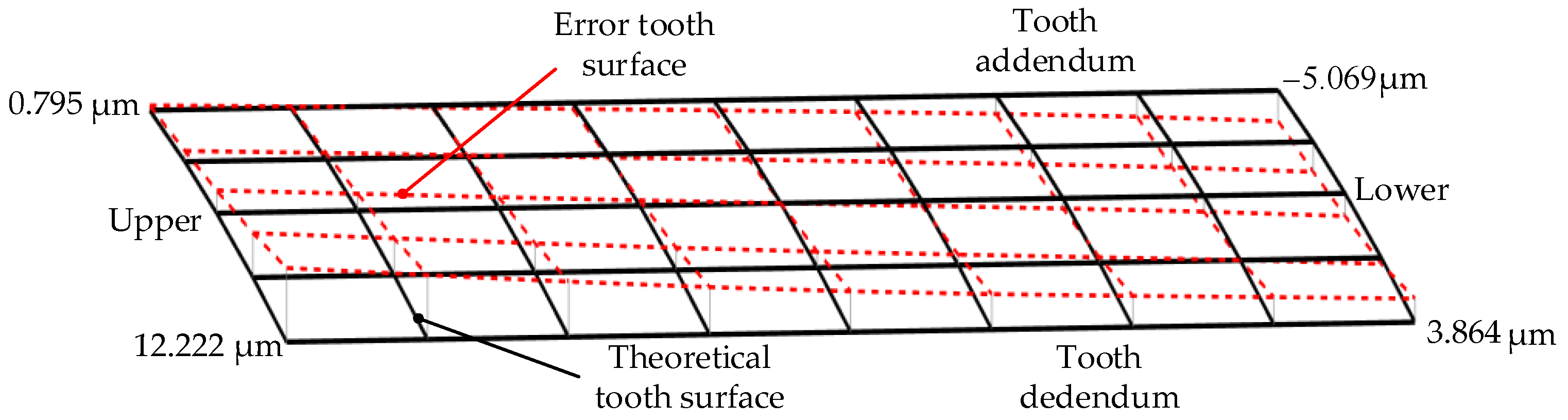
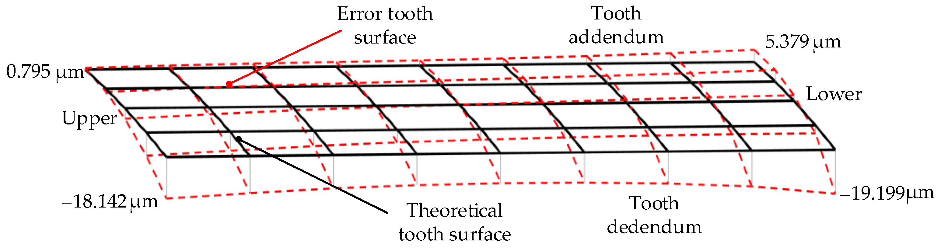
  • The distribution of the internal helical gear tooth surface deviation is analyzed in the presence of four kinds of drum-shaped grinding tool installation errors. The results indicate that varying degrees of distortion along both the tooth height and width directions on the tooth surface of the internal helical gear occur when there are installation errors in the drum-shaped grinding tool. The research provided a theoretical basis for compensating for the tooth surface of the internal helical gear.
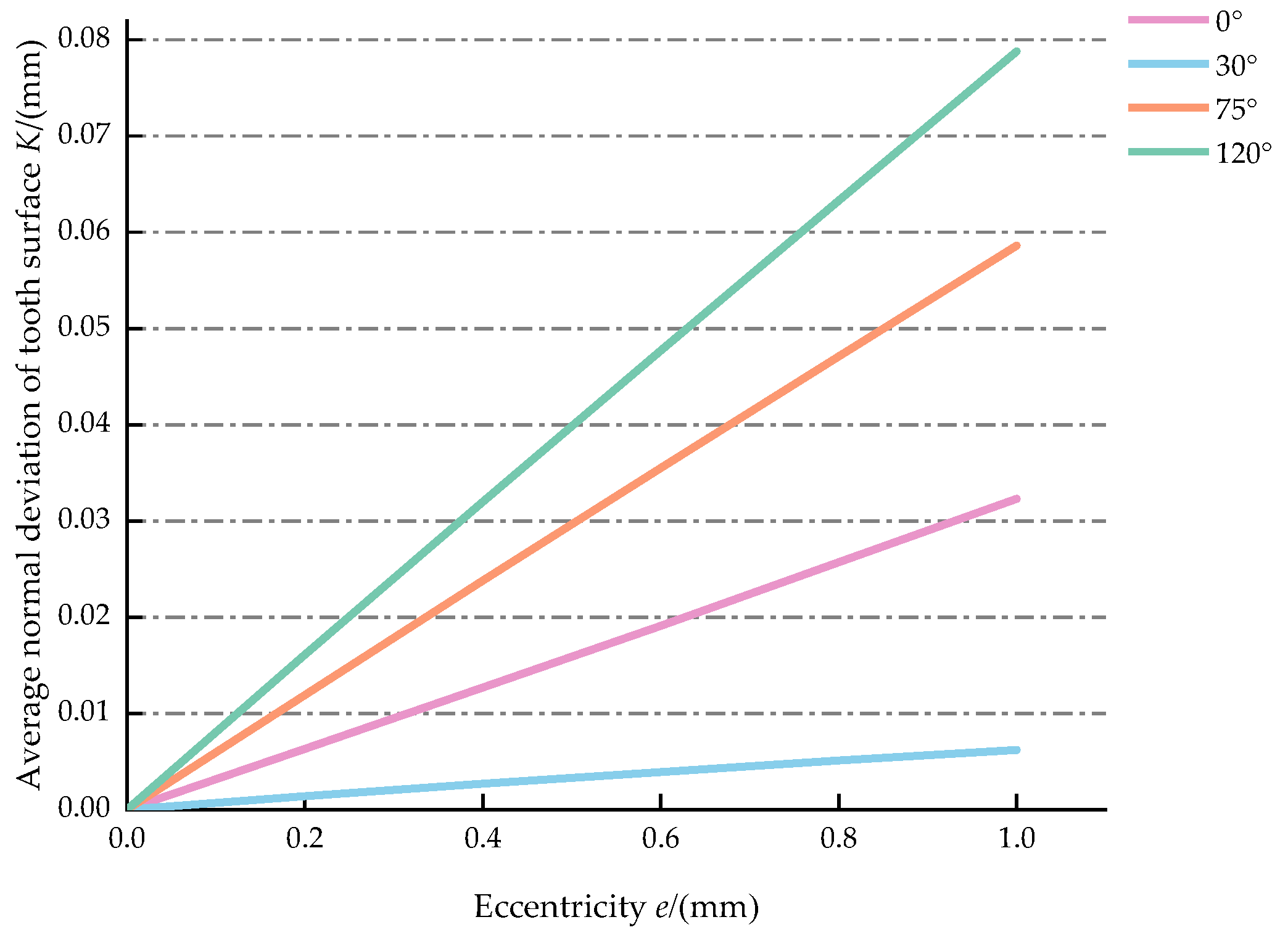
  • The average normal deviation of the tooth surface shows a periodic variation when the eccentric angle changes from −180° to 180°. The sensitive directions of eccentric error occur when the eccentric angle approaches −60° and 120°, the average normal deviation of the tooth surface reaches its maximum, while the insensitive directions of eccentric error occur when the eccentric angle approaches −150° and 30°, the average normal deviation of the tooth surface reaches its minimum. The average normal deviation of the tooth surface increases linearly with the increase in the eccentricity.
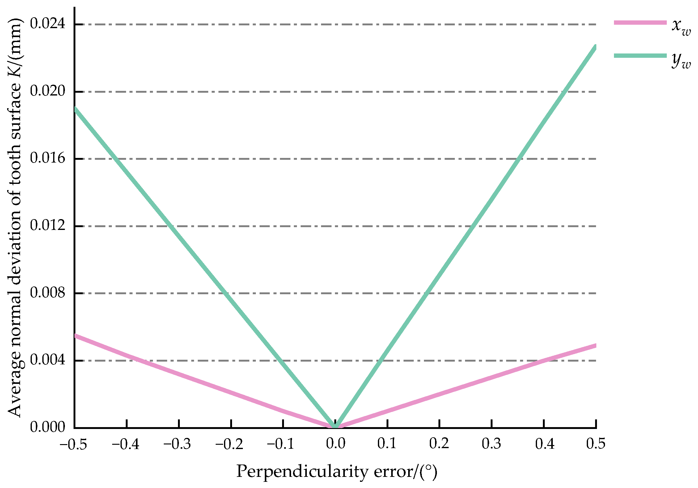
  • Leaning around the yw axis is the sensitive direction of perpendicularity error. The average normal deviation of the tooth surface is linearly related to the perpendicularity error.

Author Contributions

Conceptualization, J.Y. and Z.Z.; methodology, J.Y. and Z.Z.; validation, J.Y., Z.Z. and S.W.; formal analysis, J.W.; investigation, J.Y. and Z.Z.; resources, J.Y.; writing—original draft preparation, Z.Z.; writing—review and editing, J.Y.; supervision, S.W.; project administration, J.W.; funding acquisition, J.Y. All authors have read and agreed to the published version of the manuscript.

Funding

This research was funded by National Natural Science Foundation of China (No. 52275054), Key Research and Development Projects in Henan Province (No. 241111221200) and Frontier Exploration Project of Longmen Laboratory (No. LMQYTSKT023).

Institutional Review Board Statement

Not applicable.

Informed Consent Statement

Not applicable.

Data Availability Statement

The original contributions presented in the study are included in the article, further inquiries can be directed to the corresponding author.

Conflicts of Interest

The authors declare no conflicts of interest.

References

  1. Krajnik, P.; Hashimoto, F.; Karpuschewski, B.; da Silva, E.; Axinte, D. Grinding and fine finishing of future automotive powertrain components. CIRP Ann.-Manuf. Technol. 2021, 70, 589–610. [Google Scholar] [CrossRef]
  2. Mather, N.T.; Vijayaraghavan, L. Wear of silicon carbide wheel during grinding of intermetallic titanium aluminide. Int. J. Mach. Mach. Mater. 2020, 22, 122–136. [Google Scholar]
  3. Liu, X.; Wang, S.; Yue, C.; Xu, M.; Chen, Z.; Zhou, J.; Liang, S. Numerical calculation of grinding wheel wear for spiral groove grinding. Mater. Sci. Forum. 2022, 120, 3393–3404. [Google Scholar] [CrossRef]
  4. Onishi, T.; Murata, Y.; Fujiwara, K.; Sakakura, M.; Ohashi, K. Accurate estimation of workpiece dimension in plunge grinding without sizing gauge. Precis. Eng.-J. Int. Soc. Precis. Eng. Nanotechnol. 2022, 74, 441–446. [Google Scholar] [CrossRef]
  5. MA, X.F.; Cai, Z.Q.; Yao, B.; Chen, G.F.; Liu, W.S.; Qiu, K.X. Dynamic grinding force model for face gear based on the wheel-gear contact geometry. J. Mater. Process. Technol. 2022, 306, 117633. [Google Scholar] [CrossRef]
  6. Cai, S.J.; Cai, Z.Q.; Yao, B.; Shen, Z.H.; Liu, J.C.; Huang, H.P.; Lin, B.J.; Lin, J.C.; Huang, H.B. Face gear generating grinding residual model based on the normal cutting depth iterative method. Int. J. Adv. Manuf. Technol. 2023, 126, 355–369. [Google Scholar] [CrossRef]
  7. Ophey, M.; Klocke, F.; Loepenhaus, C. Approach for modeling grinding worm wear in generating gear grinding. Forsch. Ing. wes.-Eng. Res. 2017, 81, 307–316. [Google Scholar] [CrossRef]
  8. Yu, B.; Kou, H.L.; Zhao, B.Y.; Shi, Z.Y.; Sun, Y.Q.; Wu, G.Q. Approximation model for longitudinal-crowned involute helical gears with flank twist in continuous generating grinding. Int. J. Adv. Manuf. Technol. 2021, 114, 3675–3694. [Google Scholar] [CrossRef]
  9. Cao, B.; Li, G.L.; Alessandro, F.; Ni, H.X. Continuous generating grinding method for beveloid gears and analysis of grinding characteristics. Adv. Manuf. 2022, 10, 459–478. [Google Scholar] [CrossRef]
  10. Zhou, W.H. Residual stress evolution for tooth double-flank by gear form grindin. J. Manuf. Process. 2022, 77, 754–769. [Google Scholar]
  11. Taku, U.; Terashima, K.; Sakamoto, M. Studies on the internal gear hobs-hobs working like the broach and their cutting test. Bull. JSME 1975, 18, 73–80. [Google Scholar]
  12. Guo, Z.; Mao, S.M.; Liang, H.Y.; Duan, D.S. Research and improvement of the cutting performance of skiving tool. Mech. Mach. Theory 2018, 120, 302–313. [Google Scholar] [CrossRef]
  13. Guo, Z.; Mao, S.M.; Du, X.F.; Ren, Z.Y. Influences of tool setting errors on gear skiving accuracy. Int. J. Adv. Manuf. Technol. 2017, 91, 3135–3143. [Google Scholar] [CrossRef]
  14. Tsai, C. Mathematical model for design and analysis of power skiving tool for involute gear cutting. Mech. Mach. Theory 2016, 101, 195–208. [Google Scholar] [CrossRef]
  15. Tsai, C. Power-skiving tool design method for interference-free involute internal gear cutting. Mech. Mach. Theory 2021, 164, 104396. [Google Scholar] [CrossRef]
  16. Trong, T.L.; Wu, Y.R. A Novel approach to attain tooth flanks with variable pressure and helical angles utilizing the same cutter in the CNC gear skiving process. Int. J. Adv. Manuf. Technol. 2022, 123, 875–902. [Google Scholar]
  17. Shih, Y.P.; Li, Y.J. A Novel Method for Producing a Conical Skiving Tool with Error-Free Flank Faces for Internal Gear Manufacture. J. Mech. Des. 2018, 140, 043302. [Google Scholar] [CrossRef]
  18. Guo, E.K.; Hong, R.J.; Huang, X.D.; Fang, C.G. Research on the design of skiving tool for machining involute gears. J. Mech. Sci. Technol. 2014, 28, 5107–5115. [Google Scholar] [CrossRef]
  19. Guo, E.K.; Hong, R.J.; Huang, X.D.; Fang, C.G. A correction method for power skiving of cylindrical gears lead modification. J. Mech. Sci. Technol. 2015, 29, 4379–4386. [Google Scholar] [CrossRef]
  20. Guo, E.K.; Hong, R.J.; Huang, X.D.; Fang, C.G. Research on the cutting mechanism of cylindrical gear power skiving. Int. J. Adv. Manuf. Technol. 2015, 79, 541–550. [Google Scholar] [CrossRef]
  21. Guo, E.K.; Ren, N.F.; Ren, X.D.; Liu, C.X. An efficient tapered tool having multiple blades for manufacturing cylindrical gears with power skiving. Int. J. Adv. Manuf. Technol. 2019, 102, 2823–2832. [Google Scholar] [CrossRef]
  22. Osafune, T.; Nakamura, M.; Iba, D. Tooth geometry design of cylindrical skiving cutter for internal gears: An attempt to optimization. In Proceedings of the Machine Design and Tribology Division Metting, Fukui, Japan, 18–19 April 2016; p. B4-1. [Google Scholar]
  23. Uriu, K.; Osafune, T.; Murakami, T.; Nakamura, M.; Iba, D.; Funamoto, M.; Moriwaki, I. Effects of shaft angle on cutting tool parameters in internal gear skiving. Mech. Sci. Technol. 2017, 31, 5665–5673. [Google Scholar] [CrossRef]
  24. Ren, Z.W.; Fang, Z.L.; Kobayashi, G.; Kizaki, T.; Sugita, N.; Nishikawa, T.; Kugo, J.; Nabata, E. Influence of tool eccentricity on surface roughness in gear skiving. Precis. Eng.-J. Int. Soc. Precis. Eng. 2020, 63, 170–176. [Google Scholar] [CrossRef]
  25. Jia, K.; Guo, J.K.; Ma, T.; Wan, S.K. Mathematical modelling of power skiving for general profile base on numerical enveloping. Int. J. Adv. Manuf. Technol. 2021, 116, 733–746. [Google Scholar] [CrossRef]
  26. Li, J.; Wang, P.; Chen, X.C.; Yang, T.J. A study on the optimal selection of spur slice cutter parameters and machining parameters . Int. J. Adv. Manuf. Technol. 2016, 82, 407–417. [Google Scholar] [CrossRef]
  27. Li, J.; Wang, P.; Jin, Y.Q.; Hu, Q.; Chen, X.C. Cutting force calculation for gear slicing with energy method. Int. J. Adv. Manuf. Technol. 2016, 83, 887–896. [Google Scholar] [CrossRef]
  28. Chen, X.C.; Li, J.; Lou, B.C. A study on the design of error-free spur slice cutter. Int. J. Adv. Manuf. Technol. 2013, 68, 727–738. [Google Scholar] [CrossRef]
  29. Chen, X.C.; Li, J.; Zou, Y.; Wang, P. A study on the grinding of the major flank face of error-free spur slice cutter. Int. J. Adv. Manuf. Technol. 2014, 72, 425–438. [Google Scholar] [CrossRef]
  30. Yanase, Y.; Komori, M.; Ochi, M. Grinding of internal gears by setting a large crossed-axes angle using a barrel-shaped grinding wheel. Precis. Eng.-J. Int. Soc. Precis. Eng. 2018, 52, 384–391. [Google Scholar] [CrossRef]
  31. Chen, Y.H.; Zhang, G.H.; Chen, B.K.; Luo, W.J.; Li, F.J.; Chen, Y. A novel enveloping worm pair via employing the conjugating planar internal gear as counterpart. Mech. Mach. Theory 2013, 67, 17–31. [Google Scholar] [CrossRef]
Figure 1. Transverse profiles of the internal helical gear and a single tooth: (a) entire transverse profile; (b) a single tooth transverse profile.
Applsci 14 06551 g001
Figure 2. Discretization of the tooth surface of internal helical gear.
Applsci 14 06551 g002
Figure 3. Internal helical gear grinding using the drum-shaped grinding tool.
Applsci 14 06551 g003
Figure 4. Coordinate system applied for continuous generation grinding of internal helical gear.
Applsci 14 06551 g004
Figure 5. Tooth surfaces of drum-shaped grinding tool and internal helical gear: (a) left tooth surface; (b) right tooth surface.
Applsci 14 06551 g005
Figure 6. Assembly model of drum-shaped grinding tool and internal helical gear: (a) entire view; (b) enlarged view.
Applsci 14 06551 g006
Figure 7. Model of the drum-shaped grinding tool installation error.
Applsci 14 06551 g007
Figure 8. Deviation distribution of internal helical gear tooth surface involving error A.
Applsci 14 06551 g008
Figure 9. Deviation distribution of internal helical gear tooth surface involving error B.
Applsci 14 06551 g009
Figure 10. Deviation distribution of internal helical gear tooth surface involving error C.
Applsci 14 06551 g010
Figure 11. Deviation distribution of internal helical gear tooth surface involving error D.
Applsci 14 06551 g011
Figure 12. Variation law of average normal deviation of tooth surface with the eccentric angle.
Applsci 14 06551 g012
Figure 13. Variation law of average normal deviation of tooth surface with the eccentricity.
Applsci 14 06551 g013
Figure 14. Variation law of average normal deviation of tooth surface with perpendicularity error.
Applsci 14 06551 g014
Table 1. Basic parameters of the internal helical gear and the drum-shaped grinding tool.
ParametersInternal Helical GearDrum-Shaped Grinding Tool
Module(mm)2.75
No. of teeth8620
Pressure angle (°)2020
Helical angle (°)1247
Modification−0.35550.3555
Hand of threadRight-hand
Shaft angle (°)35
Table 2. Drum-shaped grinding tool installation errors.
Group. NoEccentricity
e (mm)
Eccentric Angle
α (°)
Perpendicularity
φx (°)
Perpendicularity
φy (°)
A0.53000
B0.512000
C00−0.50
D000−0.5
Disclaimer/Publisher’s Note: The statements, opinions and data contained in all publications are solely those of the individual author(s) and contributor(s) and not of MDPI and/or the editor(s). MDPI and/or the editor(s) disclaim responsibility for any injury to people or property resulting from any ideas, methods, instructions or products referred to in the content.

