Article

The Potential of Fiber-Reinforced Concrete to Reduce the Environmental Impact of Concrete Construction

by
Marcos G. Alberti
1,*,
Alejandro Enfedaque
1,
Duarte M. V. Faria
2 and
Miguel Fernández Ruiz
1
1
E.T.S.I de Caminos, Canales y Puertos, Universidad Politécnica de Madrid, C/Profesor Aranguren, 3, Ciudad Universitaria, 28040 Madrid, Spain
2
MFIC Ingénieurs Civils SA, 1110 Morges, Switzerland
*
Author to whom correspondence should be addressed.
Appl. Sci. 2024, 14(15), 6629; https://doi.org/10.3390/app14156629 (registering DOI)
Submission received: 30 June 2024 / Revised: 26 July 2024 / Accepted: 27 July 2024 / Published: 29 July 2024

Abstract

:
Material optimization was one of the challenges for achieving cost-competitive solutions when concrete was introduced in construction, leading to new structural shapes for both civil works and buildings. As concrete construction became dominant, saving material was given less significance, and the selection of the structural typology was mostly influenced by construction or architectural considerations. Simple and non-time-consuming methods for building thus arose as the dominant criteria for design, and this led to the construction of less efficient structures. Currently, the awareness of the environmental footprint in concrete construction has brought the focus again to the topic of structural efficiency and material optimization. In addition, knowledge of material technology is pushing the use of cements and binders with lower environmental impact. Within this framework, Fiber-Reinforced Concrete (FRC) has been identified as a promising evolution of ordinary concrete construction. In this paper, a discussion is presented on the structural properties required for efficient design, focusing on the toughness and deformation capacity of the material. By means of several examples, the benefits and potential application of limit analysis to design at the Ultimate Limit State with FRC are shown. On this basis, the environmental impact of a tailored mix design and structural typology is investigated for the case of slabs in buildings, showing the significant impact that might be expected (potentially reducing CO2-eq emissions to half or even less in slabs when compared to ordinary solutions).

1. Introduction

Currently, the greatest challenge that mankind faces is the response to anthropogenic climate change [1] from an environmental and economic perspective [2]. Within this framework, it is an urgent social responsibility toward future generations to reduce the impact that mankind is having on the environment [3,4]. Considering that the contribution of the construction and building industry to global GHG emissions is around 40%, reducing this figure is of utmost importance and has been included as a main goal in most countries [5,6,7]. To that end, the concept of sustainable construction was developed. It may be defined as the efficient use of resources with ecological design and includes social, economic, biophysical, and technical aspects [8]. Given that this paper focuses on the contribution of Fiber-Reinforced Concrete (FRC) to the reduction of environmental impact, only biophysical and technical aspects will be considered.
Regarding the reduction of air pollution, it should be noted that around 5–7% of the total amount of CO2 emissions comes from cement production, which accounts for around 25% of the emissions of the construction industry [9,10]. The majority of such CO2 production is, in fact, related to cement production due to fuel consumption needed for the calcination of limestone [11] and the chemical reactions induced. Some strategies to reduce the footprint associated with cement production are thus related to its production (see, for instance, [12]). However, the most efficient way to reduce cement consumption is directly linked to the rational use of this resource by reducing the amount of clinker needed for cement production [13,14] as well as by designing efficient structures with low consumption of concrete [15]. In this respect, the interest in the use of FRC for concrete construction is currently being actively investigated in terms of the economy of construction and the reduction of carbon footprint [16,17,18,19,20]. Such works have highlighted the potential of the material to lead to structural designs aligned with the pillars of sustainability [15]. In this regard, it is important to emphasize that the presence of fiber enhances the durability and lifespan of the material due to the reduction in the width of the cracks [21,22].
As shown by the experience of reinforced concrete construction, exploiting the potential of FRC in view of its application as a more sustainable solution will require not only tailored mixes to reduce the carbon footprint but also suitable structural typologies to minimize material consumption. To that end, the use of fibers can efficiently replace shear reinforcement [23] and eliminate [20] or reduce [24] the necessity of arranging a minimal amount of reinforcement for suitable control of cracking. This fact raises the issue that focusing design efforts only on the material mix or only on the typology is not sufficient and that both shall converge in the adoption of suitable structural shapes. It may be noted that such consideration is not suitably addressed in the literature, and this topic will be investigated in detail in the present manuscript.
Within this framework, a relevant aspect related to the design of members cast with FRC is their brittle or ductile structural response, which depends both on the material behavior and on the structural configuration. These aspects, concerning the toughness of the material and the structural configuration, are not always suitably accounted for in design but shall be recalled as being instrumental for the design of a structure. In this paper, the structural behavior of FRC is investigated and its material and structural responses in a coupled manner are considered. This is performed by analyzing several cases of tension and bending. To that end, the role of toughness in the structural response is first investigated with reference to members in tension, showcasing its significance under various scenarios. Then, the response in bending is critically analyzed, and an approach based on limit analysis is presented and compared to available tests, overcoming some theoretical flaws of previous approaches. This knowledge is eventually combined for the bending design of flat slabs supported on columns, where an exact solution according to limit analysis is presented and eventually used to assess the potential savings in terms of carbon footprint in construction. On this basis, the investigation discusses the most advantageous design strategies for material and structure selection, as well as the potential benefits of using FRC as an evolution of ordinary reinforced concrete. The analyses performed also highlight the significant expected reductions of carbon footprint in construction by following this approach. In particular, the case of a conventional flat slab is investigated by optimizing both its material and structural typology. The results show that significant reductions can be expected in terms of carbon footprint by reducing the embodied amount of CO2-eq by half or even more.

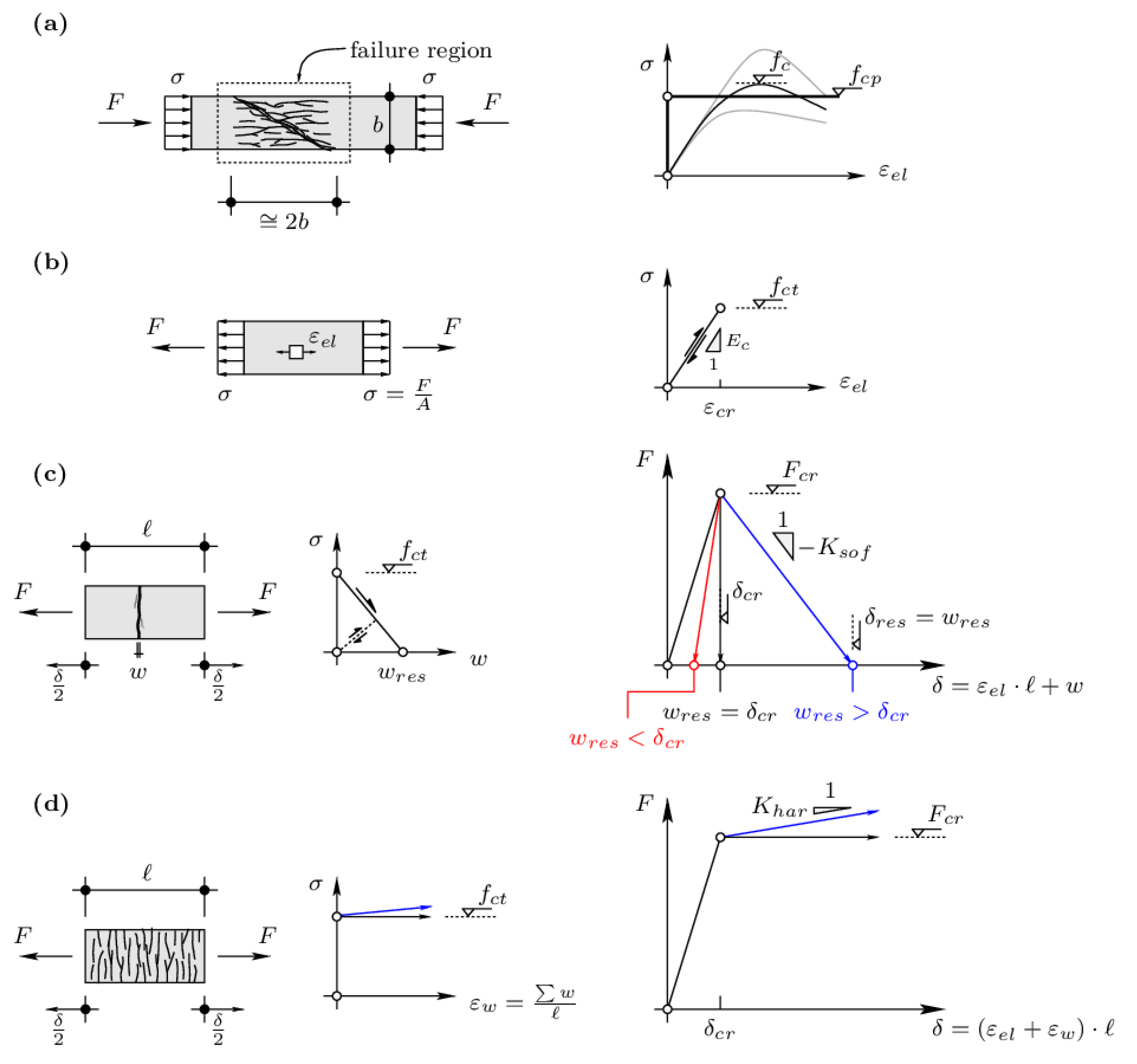
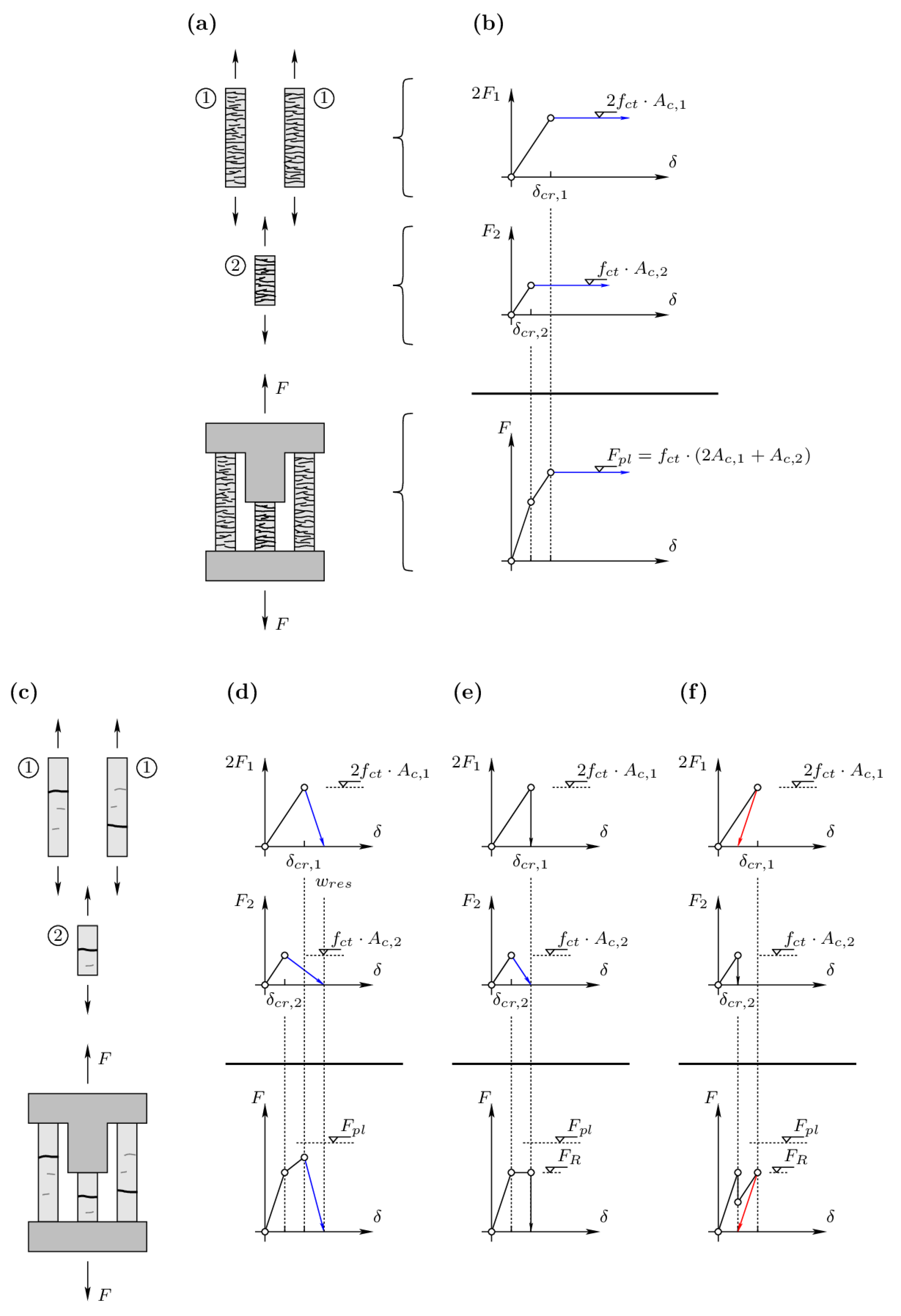
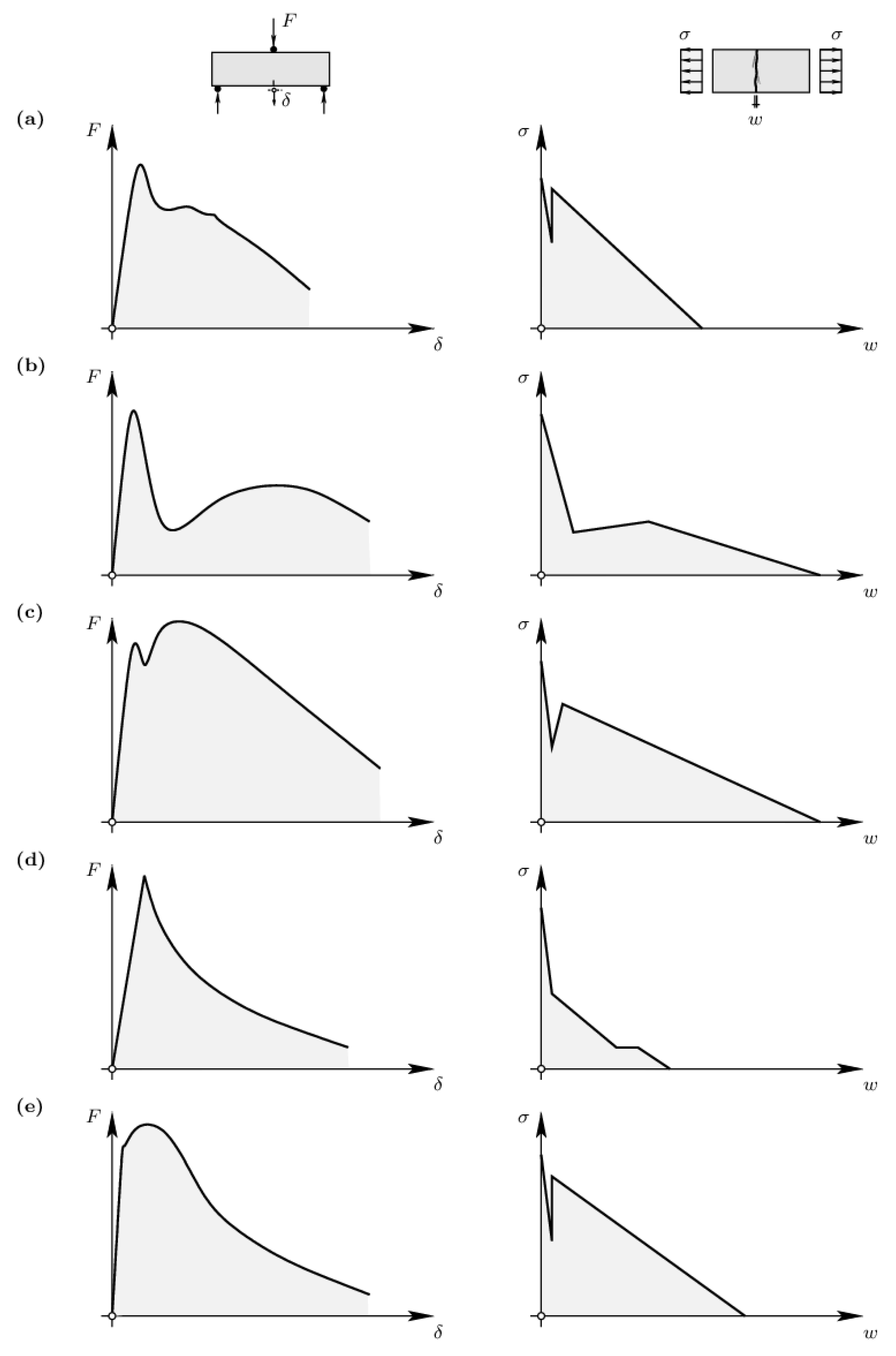
2. Influence of Material and Mechanical Parameters on Structural Response and Toughness

Concerning structural design, different strategies may be adopted depending on the expected structural response and namely on the potential of the structure to redistribute internal forces. Two responses can, in general, be identified: those related to strain softening and those where the material can develop relatively large plastic deformations (or even harden while deforming plastically).
The former (strain softening) is associated with brittle responses with potential strain localization, as the weakest section governs not only the strength but also the deformation capacity. In concrete, such strain localization develops at a single critical crack, whose progression leads to the failure of the element. Such strain localization is typically found in elements subjected to tensile or shear stresses and without reinforcement to control cracking [25]. However, even in cases where reinforcement is provided, strain localization may occur due to the geometry or in the presence of strong gradients of internal forces (as typically found for punching). Other than limiting the structural resistance by the capacity of the weakest element, it shall be noted that cases where brittle responses might be expected are also sensitive to imposed deformations, such as temperature, self-stresses, or support settlements.
Concerning cases of ductile responses, plastic regions develop, allowing for large deformation capacities while the structural resistance is maintained (or even increased in case of strain hardening) [26]. This allows for the redistribution of internal forces between different elements of a system, and the structural resistance is eventually a result of the individual resistance of its components (and not governed by the strength of the weakest region). Also, such a response allows removing any potential effect of previous states of stresses (and thus of self-stresses or imposed strains) on the structural resistance.
It shall be noted that in the case where the response of a member is not fully plastic, different levels of material toughness may be found. For instance, for concrete under compression, Figure 1a, compression softening occurs in a region whose length is approximately twice the cross-section dimension (for a typical value of the friction angle of the material equal to 37° [27,28]). Despite the softening response and eventual localization of strains, the material has a certain level of toughness associated to the friction stresses developing at the failure surface. This allows for the application of plastic design methods [28], by suitably reducing the compression strength to an equivalent plastic strength. In so doing, the uniaxial compressive strength may be reduced as given below (as recently adopted by EN1992-1-1:2023 [29], following the works of [30]):
f c p = f c f c 0 f c 1 3 f c
where a suitable value for fc0 is typically 30 MPa. As it can be observed (see also Figure 1a), larger reductions apply for higher values of the uniaxial compressive resistance as the response of the material becomes more brittle.
Concerning the tensile response of FRC, different responses can be expected depending on the properties of the fibers used and their dosage [31]. A detailed investigation of the structural response can be performed in a consistent manner by accounting for both the uncracked and cracked response of the material. The former is governed by an elastic response (Figure 1b), which allows for loading and unloading without any residual strain. As the level of load increases, one section may attain its tensile strength (fct) at its weakest section and develop a crack. No other cracks form thereafter, as the stress in the element softens for increasing levels of deformation. This is the case shown in Figure 1c for a simplified linear softening relationship. In such a case, the total elongation of a tie will result in the one corresponding to the uncracked region plus the opening of the crack:
δ = δ e l + w = ε e l l + w
where both ε e l and w refer to a given level of stress σ .
As it can be noted (Figure 1c), when the stress is completely released, the elongation of the tie is equal to the opening of the crack at which tensile stresses vanish ( w r e s ). This parameter is thus instrumental for the post-peak response of the system and characterizes its structural toughness (area under the force-displacement curve). As it can be noted, the slope characterizing the structural response depends on both material and geometrical parameters (with longer ties associated with more brittle responses, as the released energy in the uncracked regions is higher):
K s o f = F c r w r e s δ c r = F c r w r e s ε c r l  
This is a significant observation, as the expected structural response depends not only on the selected material but also on the structural configuration.
On the contrary, when a strain hardening response is expected (Figure 1d), multiple cracks develop (when the stresses increase for increasing levels of strain). In this case, the smeared nature of cracking allows considering an equivalent (average) strain in the tension member (refer to ε w in Figure 1d). Thus, the application of limit analysis for design, assuming smeared deformations, remains fully valid.
The responses for isolated elements previously discussed have strong implications on the structural response. Two cases can again be distinguished depending upon the material response. The former refers to a plastic response (Figure 2a), where no strain localization is expected at any element (as for Figure 1c). In this case, redistributions of internal forces happen without restriction. The structural resistance can, in this case, be determined as the load equilibrating the internal forces for a state of stresses where the yield conditions are respected and where the increment of plastic strains are compatible with an admissible failure mechanism (corresponding to an exact solution for associate plasticity conditions [26]). For the simple case shown in Figure 2a, such resistance corresponds to the sum of the individual resistances (Figure 2b), independently of the load path followed (disregarding, for instance, if self-stresses were present before loading).
The latter case corresponds to members where strain localization occurs (Figure 2c). In this case, the structural resistance depends on the structural toughness of its elements. For relatively tough members (Figure 2d), the load after the first event of cracking can still be increased. However, the failure load is normally reduced with respect to the theoretical plastic resistance (sum of individual resistances). When the structural toughness of its components is reduced, the structural resistance is also reduced and may be governed by the first event of cracking (Figure 2e,f). In addition, such cases are sensitive to potential self-stresses or imposed strains.
As a consequence of such behavior, it can be concluded that fully exploiting the material strength can only be achieved when a ductile response, or with sufficient deformation capacity, is available. In the case where strain localization cannot be avoided, the toughness of its elements is instrumental in avoiding brittle failures and ensuring a suitable level of redistribution of internal forces.

3. Material Considerations

In order to achieve the most sustainable application of raw materials, an efficient use of them is required. In this respect, in the absence of specific requirements for considering the structural contribution of fibers, their efficiency in tension is normally characterized by comparing their strength after cracking to the limit of proportionality of the material (fLOP, refer, for instance, to EN-14651 [32]). Thus, reducing the quality and strength of the matrix can suitably reduce fLOP and achieve an efficient fiber-matrix system, as shown in Figure 3. This consideration can lead to the use of cements with lower contents of clinker [33], clinker substitution by by-products of other industries, or even lower amounts of cement [34,35,36]. These possibilities are potential ways to reduce the impact of the material in CO2 production while increasing efficiency.
Alternative strategies can also be followed or combined with the previous one. They refer to optimizing the geometry of fibers, material types, contents, sizes, and lengths, as well as through a combination of them. Research and practice [37,38,39] have shown that for low mechanical requirements, macro-polymer fibers are, in many cases, the most attractive alternative. In these cases, it might be possible to further reduce the content of cement, leading to a bi-linear material response in tension. In case of higher requirements, a more optimal structural response can be obtained by a combination of macro-polymer fibers and steel fibers, ensuring a quasi bi-linear shape and also reductions in terms of CO2 [31]. Figure 4 sketches in a qualitative manner the main differences between the fracture behavior and the constitutive models for the FRC types described above.

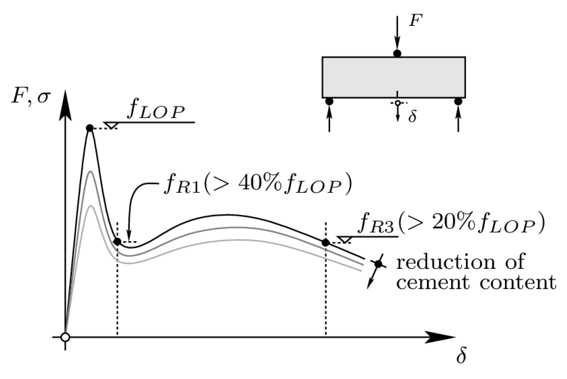
4. Considerations for Bending Design

An interesting example where the concepts of plastic regions and admissible failure mechanisms can be applied to FRC is bending design. The topic of bending design has been investigated from various perspectives in the past. For instance, several approaches propose to consider an elastic state of stresses in the compression zone while a crack opens in bending [40]. Such approaches typically require considering that the region in compression (where elastic strains are considered) is associated with a fictitious length, linearly increasing with the opening of the flexural crack [40]. Although the global response can be satisfactorily reproduced when compared to test results, such consideration presents theoretical shortcomings. For instance, the value of the peak stress is not controlled, the local strains in the compression region remain relatively low with respect to what might be expected in reality, and the meaning of the fictitious length is not connected to a physical parameter.
An alternative approach to the flexural resistance and its associated kinematics at failure can be treated within the framework of limit analysis by considering a failure mechanism for plane strain conditions, as shown in Figure 5a. Such a mechanism consists of a separation line in tension (increment of plastic strains in pure tension) as well as a plastic wedge in compression (Rankine region). Such an approach has proven to be applicable to reinforced concrete sections under bending and normal forces [41] and has been successfully applied as the ground model for validation of the EN1992-1-1:2023 [29] design expressions. For its application to FRC, the stress distribution shown in Figure 5b applies, where the corresponding flexural strength results:
M R = f f p b h 2 1 x p l h 1 x p l 2 h
where x p l refers to the height of the compression zone, whose value is determined by the following equilibrium conditions:
x p l = h f c t f c p + f f p
This term can be approximated in most cases considering x p l 0 and thus
M R 1 2 f f p b h 2
The conditions of the plastic mechanism are investigated in detail in Figure 5c–f. By assuming a rigid body motion at the tip of the separation yield line, the deformed shape of Figure 5c results. In the resulting plastic wedge (Figure 5d), the strain state can be obtained by pure kinematic conditions, where the increment of principal compressive strain results ε 2 ˙ = ψ ˙ / 4 while the corresponding increment of the principal tensile strain results ε 1 ˙ = ψ ˙ . As can be noted, the ratio between the increment of tensile and compressive strains results in 4, which corresponds to the one associated with the normality condition to the yield surface ( 4 1 + sin φ / 1 sin φ for plane strain conditions, see Figure 5e). Such a state of strains leads the plastic wedge to an axial shortening while there is a transversal expansion, typically associated with longitudinal cracking (Figure 5f).
The validity of such considerations of the failure mechanism for FRC can be easily demonstrated with the help of available tests. For instance, the classical three-point bending tests for material characterization are shown in Figure 6a. By neglecting the size of the compression region with respect to the separation yield line, the kinematics shown in Figure 6b results. As it can be noted, both the deflection and opening of the crack ( δ and CMOD, respectively, in Figure 6b) are linearly dependent on the rotation of the specimen. When this assumption is compared to the test results, its correctness can be observed, for instance, by considering the tests of Alberti et al. [40] on normalized specimens according to EN 14651:2005+A1 [32] specimens (Figure 6c). This is shown in Figure 6d, where both the deflection at mid-span and the CMOD are plotted for different specimens of the experimental series. In the plot, a linear correlation between both variables can clearly observed, with a slope suitably corresponding to the theoretical one according to the failure mechanism ( l / 4 h   1 , average of measured-to-calculated values equal to 0.95 with a Coefficient of Variation equal to 17.0%).

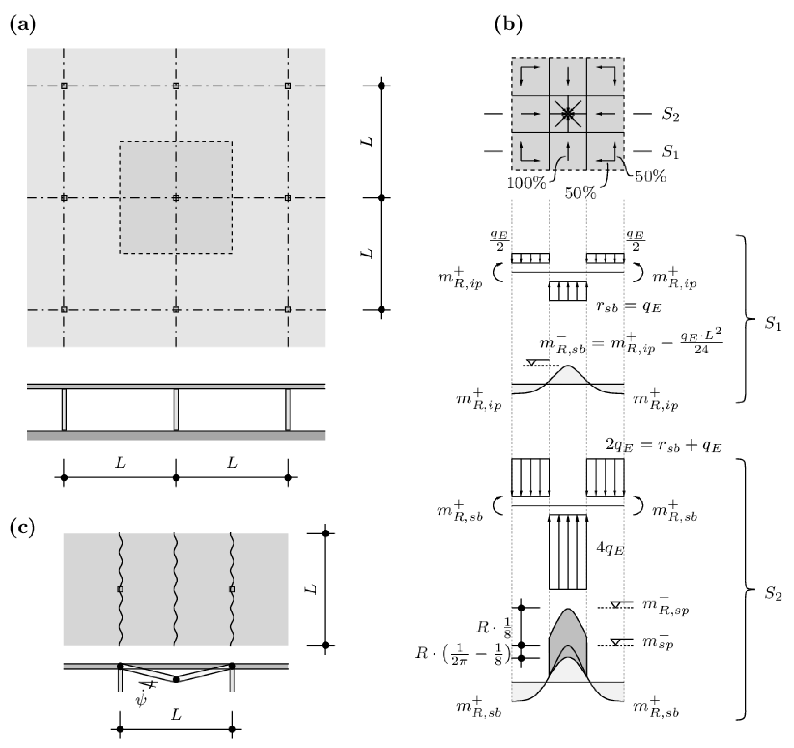
5. Considerations for Plastic Design of Flat Slabs

Integrating the considerations of plastic design is particularly relevant for redundant systems such as floor slabs [26]. Such structures allow, in fact, for multiple structural typologies, as discussed by Regúlez et al. [15], and the environmental footprint may significantly vary depending on the selection of the material and their structural efficiency. In this respect, flat slabs, which are one of the most common structural typologies used for floor slabs, can be identified as poor solutions [15] with a high environmental footprint associated with excessive material consumption.
In view of reducing the environmental footprint of flat slabs, the use of ductile FRC solutions might be a promising approach. To that end, fibers may be used to cover bending moments in the slab except in regions of high demand, typically near the supported areas, where conventional reinforcement shall additionally be arranged. Alternatively, non-metallic reinforcement, such as Textile-Reinforced Concrete [42], can also be considered, provided that the combination of fibers and textiles allows for a sufficient level of deformation capacity.
It shall be noted that the previous assumption refers to design at the Ultimate Limit State but that the distribution of fibers at the construction site might be difficult to ensure. Thus, arranging some ordinary reinforcement at regions of higher demand, such as mid-span or over-support strips, might also be convenient for control of cracking. In addition, the enhanced punching shear resistance (as fibers act as shear reinforcement) potentially avoids the necessity of arranging shear-heads, column capitals, or punching reinforcement.
The structural optimization of the reinforcement can be based on limit analysis in a simple manner. For instance, Figure 7a shows a regular flat slab whose design is performed using limit analysis in the following.

5.1. Lower Bound of the Resistance

The design is first performed by means of a lower bound of the resistance using the advanced strip method [43,44]. The band diagram and load-carrying percentages are shown in Figure 7b, as well as the resulting bending moments. As it can be noted, the maximum bending moments are located at the support panel region over the column. Elsewhere, the bending moments are relatively moderate. In fact, it can be noted that the maximum bending moments except in the support panel region can be set to the same value, where, according to the condition of the S1 band, they result in the following:
m R , i p + = m R , s b + = m R , s b = q E l 2 48
This distribution leads to an equilibrium solution as the reaction of the column results:
R = 2 4 q E + q E L 3 2 = q E L 2
This leads to a maximum negative in the support panel equal to the following:
m R , i p = 7 24 q E l 2 + m R , s b + = 13 48 q E l 2

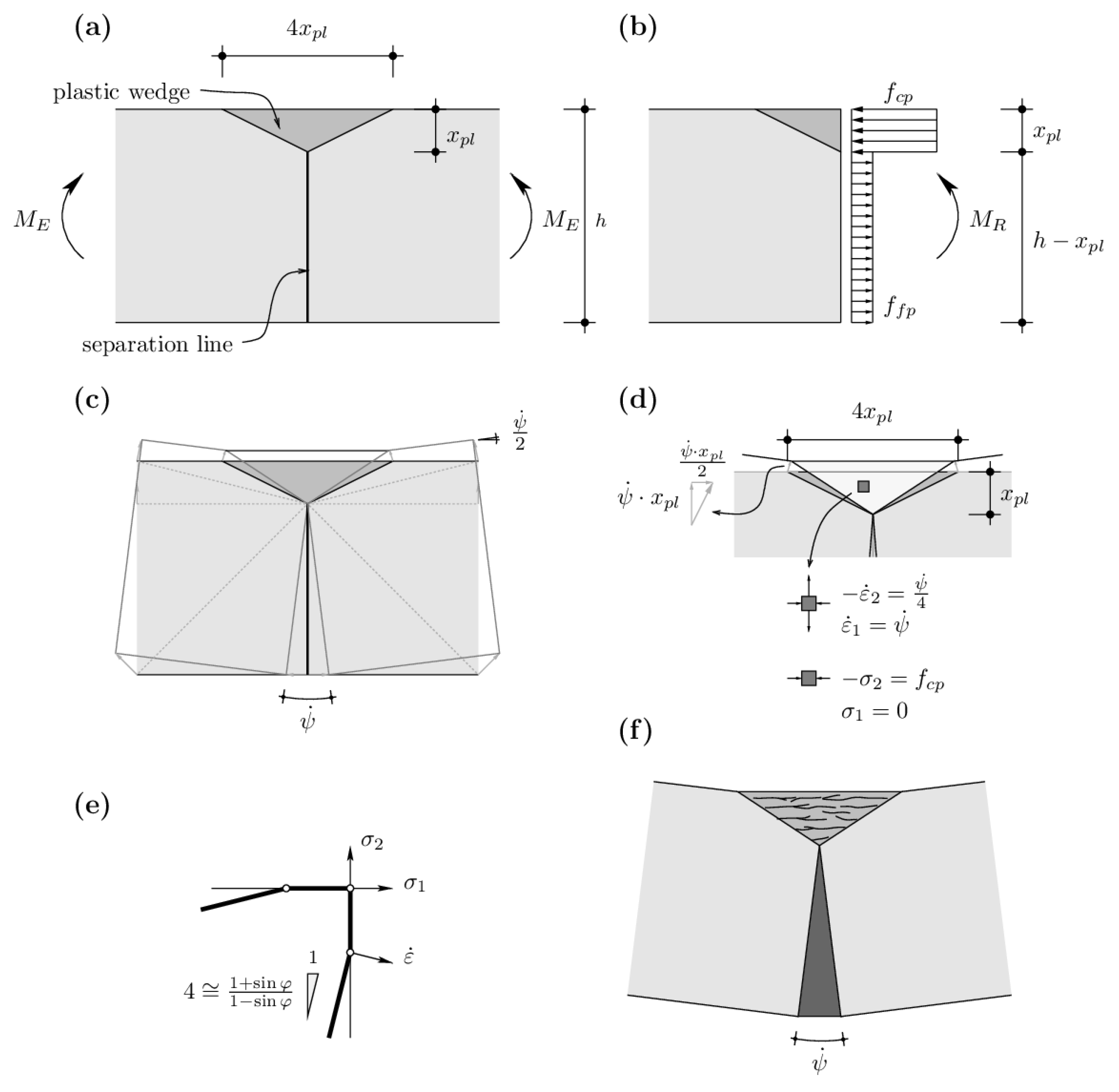
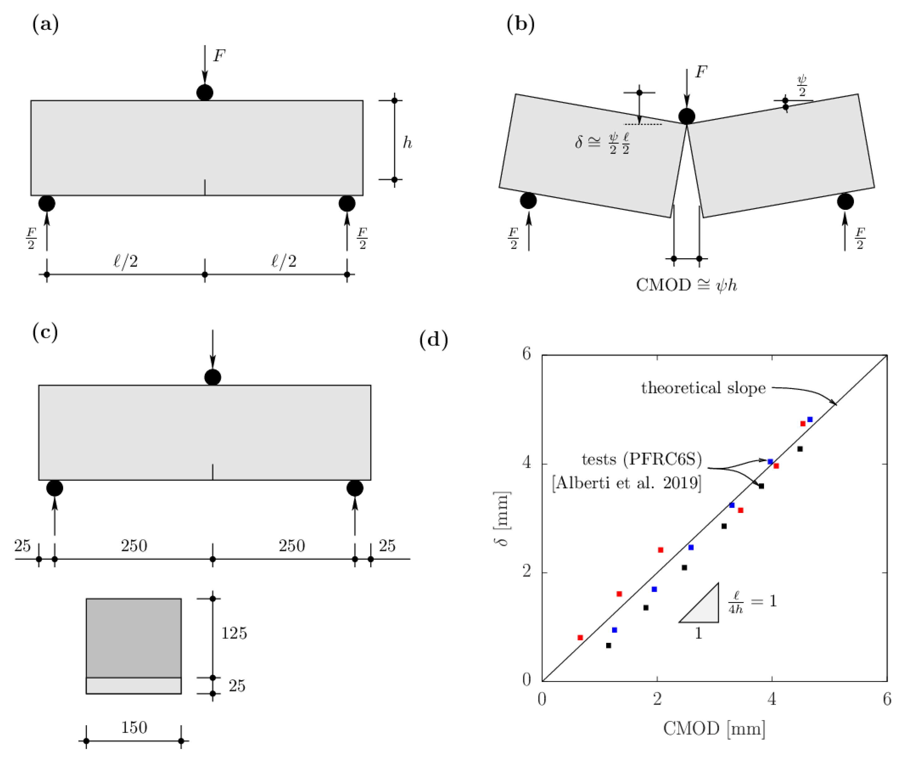
5.2. Upper Bound of the Resistance

Concerning an upper bound, the simple failure mechanism depicted in Figure 7c can be considered. In that case, the negative moment over the support panel can be calculated from the work balance between increments of external and internal work. These terms can be evaluated as follows (for half of the mechanism):
W e ˙ = q E l 3 8 ψ ˙
W i ˙ = l ψ ˙ 2 m R , i p + 3 + m R , s p + 3 2 m R , s b 3 + m R , s p 3
Thus, since W e ˙ = W i ˙ :
q E l 3 8 ψ ˙ = l ψ ˙ 2 m R , i p + 3 + m R , s p + 3 2 m R , s b 3 + m R , s p 3
This leads again to m R , i p + = m R , s b + = m R , s b = q E l 2 / 48 and:
m R , i p = 13 48 q E l 2

5.3. Comments on the Upper and Lower Bounds, Further Checks

Both the upper and lower bounds give the same resistance, meaning that it is an exact solution according to limit analysis [26]. As it can be noted, the bending moment over the inner panel ( m R , i p ) is significantly higher than in the rest of the structure, thus requiring the addition of concentrated reinforcement, while the rest of the slab could potentially be reinforced only with fibers.
It shall be observed that this analysis refers, of course, only to the Ultimate Limit State for bending, while further checks concerning the Serviceability Limit State (as deflections and cracking) may govern the value of the slab thickness as well as for the amount and type of fibers. In addition, verification of the punching resistance of the slab-column connection may govern the design of the supported area (dimensions of the column, capital, or thickness of the slab).

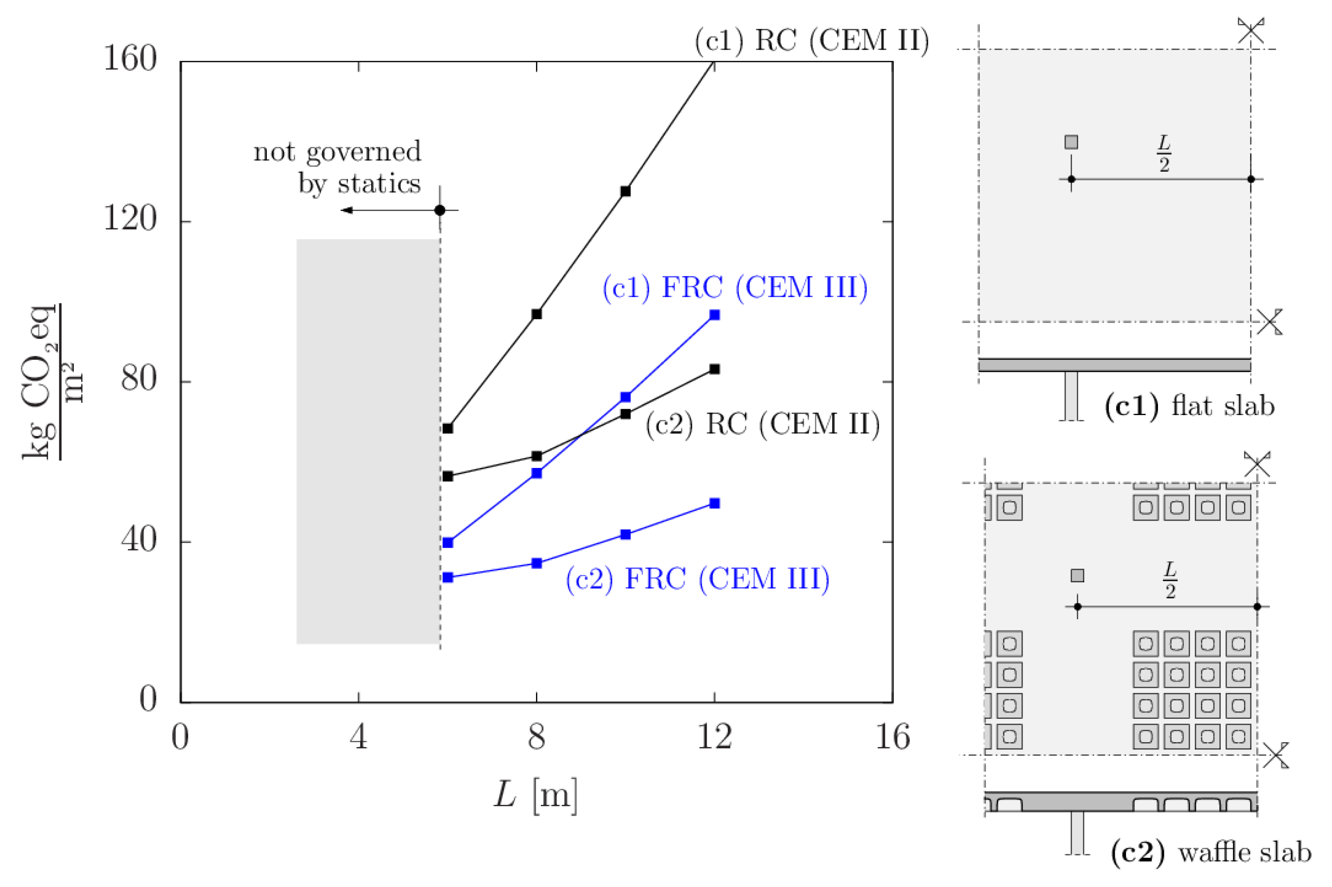
5.4. Discussion on Other Typologies and Potential Implications on Carbon Footprint

As already pointed out by Regúlez et al. [15], other structural typologies might be more efficient in terms of material consumption and overall carbon footprint. For instance, the use of waffle slabs can be identified as a promising alternative. This typology allows for the saving of large amounts of material in the inner panel regions. In addition, it is simple to cast in FRC, as flexural reinforcement may be arranged in the ribs, but shear reinforcement can be replaced by the fibers.
In the following, a comparison of a flat slab and a waffle slab is presented both in ordinary reinforced concrete and FRC, following the methodology presented in [15] and by adopting the following reference values of the unitary CO2-eq footprint:
  • Concrete C30/37 (fck = 30 MPa) CEM II for reinforced concrete elements, considering 0.12 kg CO2-eq/kg as the reference value of the unitary CO2-eq footprint [15]. Such value and cement types are selected as representative of current construction practice.
  • Concrete C30/37 (fck = 30 MPa) CEM III for FRC elements, considering 0.05 kg CO2-eq/kg as the reference value of the unitary CO2-eq footprint [15,20]. Such value is selected in order to highlight the potential of FRC to reduce the unitary carbon footprint. It shall be noted that other optimizations are possible, such as reducing the concrete strength if statically admissible.
  • Reinforcement steel B500 (fyk = 500 MPa) for both reinforced concrete and FRC solutions, considering 0.5 kg CO2-eq/kg as a reference value of the unitary CO2-eq footprint [15]
  • Polypropilene fibers, considering a ratio of 10 kg/m3. For the fibers, it is adopted a reference value of the unitary CO2-eq footprint equal to 4 kg CO2-eq/kg according to [20]
The results are plotted in Figure 8 for four representative cases, corresponding to two flat slabs (with reinforced concrete CEM II and with FRC CEM III) and to two waffle slabs (with reinforced concrete CEM II and with FRC CEM III). For the FRC solutions, flexural reinforcement was considered only in the support panel for the flat slab and in the support panel and ribs for the waffle slab. The results show a high potential to optimize the carbon footprint of the construction, with reductions in the amount of CO2-eq of more than two-thirds in several cases.
It may be yet noted that this analysis is based on the same geometry for reinforced concrete and FRC members and that only flexural checks are performed. Also, the results may vary in the considered value of the unitary CO2-eq footprint, which may experience relatively high differences among the materials considered [15]. Nevertheless, a general trend can be observed, concluding that, with respect to current construction practice, strong reductions in the environmental impact can be expected if FRC CEM III is used in optimized structural shapes. Such reduction is, in fact, mostly due to the implementation of a CEM III cement in the FRC mix with polypropylene fibers. Concerning the type of fibers to be used, the higher degrees of toughness are achieved by using macro-plymer FRC and hybrid FRC (refer to Figure 4), whose use seems thus encouraged. It shall be noted that solutions where the amount of material is significantly reduced are economically interesting, as demonstrated in [20], provided that cost-competitive solutions are found for the formwork.
Another relevant aspect for practice is the potential benefit of precasting when FRC is used. This allows for enhanced control of quality (fiber dosage and mixing) and also opens the possibility of reducing the uncertainties related to the material, thus leading to higher design values of the resistance for the same level of reliability [39]. Also, construction times are reduced, and, depending upon the construction procedure, the need for propping is also reduced. One possibility in this line could be the use of precast slab panels supported on cast-in-place strips or column capitals. This method would be similar to previous experiences performed in the 1950’s–70’s [45].

6. Conclusions

This paper presents the results of an investigation on the potential impact of Fiber-Reinforced Concrete (FRC) to reduce the environmental impact of concrete construction. Its main conclusions are listed below:
  • Design of the material properties of FRC can efficiently provide mixes associated with low embodied carbon footprint and relatively tough or ductile response after first cracking. Such mix designs are typically associated with low values of the compressive strength of concrete (sufficient in any case for usual design applications).
  • Ensuring a tough or ductile response of the material is advised as it can lead to internal force redistributions and as the strength of all elements in the structural resistance can be taken advantage of.
  • Plastic design methods are suitable for the bending design of FRC in terms of resistance and particularly of the associated kinematics and mechanism at failure.
  • Concerning the field of sustainability, the design of slabs with optimized FRC mixes and structural typologies leads to significant savings in terms of the expected carbon footprint in construction. For instance, designing FRC waffle slabs with CEM III cement may lead to cutting CO2-eq emissions by half or even two-thirds when compared to typical current solutions based on reinforced concrete flat slabs with CEM II cement.
The facts and theoretical research results presented in this paper confirm FRC as a promising way to reduce the carbon footprint of concrete construction. However, it will require a joint effort by researchers, designers, contractors, and owners to further push this option in the coming years.

Author Contributions

Conceptualization, A.E., D.M.V.F., M.F.R. and M.G.A.; methodology, A.E., D.M.V.F., M.F.R. and M.G.A.; software, A.E., D.M.V.F., M.F.R. and M.G.A.; validation, A.E., D.M.V.F., M.F.R. and M.G.A.; formal analysis, A.E., D.M.V.F., M.F.R. and M.G.A.; investigation, A.E., D.M.V.F., M.F.R. and M.G.A.; resources, A.E., D.M.V.F., M.F.R. and M.G.A.; data curation, A.E., D.M.V.F., M.F.R. and M.G.A.; writing—original draft preparation, A.E., D.M.V.F., M.F.R. and M.G.A.; writing—review and editing, A.E., D.M.V.F., M.F.R. and M.G.A.; visualization, A.E., D.M.V.F., M.F.R. and M.G.A.; supervision, A.E., D.M.V.F., M.F.R. and M.G.A.; project administration, A.E., D.M.V.F., M.F.R. and M.G.A.; funding acquisition, M.F.R. All authors have read and agreed to the published version of the manuscript.

Funding

This work has been performed within the framework of the research project PID2021-127920NB-I00 “A transition to sustainable construction using cementitious-based materials: Textile Reinforced Concrete for structural applications” funded by the call MCIN/AEI/10.130 39/501100011033/FEDER,UE (Ministerio de Ciencia e Innovación, Agencia Estatal de Investigación, Spain, cofunded by the European Union).

Data Availability Statement

The raw data supporting the conclusions of this article will be made available by the authors on request.

Conflicts of Interest

Author Duarte M. V. Faria was employed by the company MFIC ingénieurs civils SA. The remaining authors declare that the research was conducted in the absence of any commercial or financial relationships that could be construed as a potential conflict of interest.

Notation

Across-sectional area
Acconcrete cross-sectional area
Ecmodulus of elasticity of concrete
Fforce
Fcrforce at the onset of cracking
Fplplastic resistance
Kharhardening stiffness
Ksofsoftening stiffness
Lbay span
MEacting moment
MRbending resistance
Rcolumn reaction
Wwork
Weexternal work
Wiinternal work (dissipation)
bwidth
fcpuniaxial compressive strength of concrete
fcpuniaxial plastic compressive strength of concrete
fcttensile strength of concrete
hheight, thickness
l span
munitary moment
mRunitary bending strength
qEacting load
wcrack opening
wresresidual crack opening (crack opening when tensile stress vanishes)
xpldepth of plastic zone
δ displacement, elongation
δ c r displacement at the onset of cracking
δ e l elastic displacement
δ r e s residual displacement at wres
ε strain
ε e l elastic strain
ε w average strain in smeared cracked region
φ internal angle of friction of concrete
ψ rotation
σ stress

References

  1. Faruque, M.O.; Rabby, M.A.J.; Hossain, M.A.; Islam, M.R.; Rashid, M.M.U.; Muyeen, S.M. A comparative analysis to forecast carbon dioxide emissions. Energy Rep. 2022, 8, 8046–8060. [Google Scholar] [CrossRef]
  2. Rosa, E.A.; Dietz, T. Human drivers of national greenhouse-gas emissions. Nat. Clim. Change 2012, 2, 581–586. [Google Scholar] [CrossRef]
  3. Sarkar, M.S.K.; Sadeka, S.; Sikdar, M.M.H. Energy consumption and CO2 emission in Bangladesh: Trends and policy implications. Asia Pac. J. Energy Environ. 2018, 5, 41–48. [Google Scholar] [CrossRef]
  4. Pang, R.Z.; Deng, Z.Q.; Hu, J.L. Clean energy use and total-factor efficiencies: An international comparison. Renew. Sustain. Energy Rev. 2015, 52, 1158–1171. [Google Scholar] [CrossRef]
  5. Lu, M.; Lai, J. Review on carbon emissions of commercial buildings. Renew. Sustain. Energy Rev. 2020, 119, 109545. [Google Scholar] [CrossRef]
  6. Burciaga, U.M. Sustainability assessment in housing building organizations for the design of strategies against climate change. HighTech Innov. J. 2020, 1, 136–147. [Google Scholar] [CrossRef]
  7. Wang, Z.; Chen, H.; Huo, R.; Wang, B.; Zhang, B. Marginal abatement cost under the constraint of carbon emission reduction targets: An empirical analysis for different regions in China. J. Clean. Prod. 2020, 249, 119362. [Google Scholar] [CrossRef]
  8. Hill, R.C.; Bowen, P.A. Sustainable construction: Principles and a framework for attainment. Constr. Manag. Econ. 1997, 15, 223–239. [Google Scholar] [CrossRef]
  9. Worrell, E.; Price, L.; Martin, N.; Hendriks, C.; Meida, L.O. Carbon dioxide emissions from the global cement industry. Annu. Rev. Energy Environ. 2001, 26, 303–329. [Google Scholar] [CrossRef]
  10. Zhu, Q. CO2 Abatement in the Cement Industry; IEA Clean Coal Centre: London, UK, 2011. [Google Scholar]
  11. Deja, J.; Uliasz-Bochenczyk, A.; Mokrzycki, E. CO2 emissions from Polish cement industry. Int. J. Greenh. Gas Control 2010, 4, 583–588. [Google Scholar] [CrossRef]
  12. Moumin, G.; Ryssel, M.; Zhao, L.; Markewitz, P.; Sattler, C.; Robinius, M.; Stolten, D. CO2 emission reduction in the cement industry by using a solar calciner. Renew. Energy 2020, 145, 1578–1596. [Google Scholar] [CrossRef]
  13. Thomas, M.; Barcelo, L.; Blair, B.; Cail, K.; Delagrave, A.; Kazanis, K. Lowering the carbon footprint of concrete by reducing clinker content of cement. Transp. Res. Rec. 2012, 2290, 99–104. [Google Scholar] [CrossRef]
  14. Yang, K.H.; Jung, Y.B.; Cho, M.S.; Tae, S.H. Effect of supplementary cementitious materials on reduction of CO2 emissions from concrete. J. Clean. Prod. 2015, 103, 774–783. [Google Scholar] [CrossRef]
  15. Regúlez, B.; Faria, D.; Todisco, L.; Ruiz, M.F.; Corres, H. Sustainability in construction: The urgent need for new ethics. Struct. Concr. 2023, 24, 1893–1913. [Google Scholar] [CrossRef]
  16. Pujadas, P.; Blanco, A.; Cavalaro, S.; Aguado, A.; Grünewald, S.; Blom, K.; Walraven, J.C. Plastic fibres as the only reinforcement for flat supended slabs: Parametric study and design considerations. Constr. Build. Mater. 2014, 70, 88–96. [Google Scholar] [CrossRef]
  17. Pons, O.; Casanovas-Rubio, M.; Armengou, J.; de la Fuente, A. Sustainability-driven decision-making model: Case study of fiber-reinforced concrete foundation piles. J. Constr. Eng. Manag. 2021, 147, 04021116. [Google Scholar] [CrossRef]
  18. de la Fuente, A.; Casanovas-Rubio, M.; Pons, O.; Armengou, J. Sustainability of column-supported RC slabs: Fibre reinforcement as an alternative. J. Constr. Eng. Manag. 2019, 145, 1–12. [Google Scholar] [CrossRef]
  19. Aidarov, S.; Nadazdi, A.; Pugach, E.; Tosic, N.; de la Fuente, A. Cost oriented analysis of fibre reinforced concrete column-supported flat slabs construction. J. Build. Eng. 2022, 51, 104205. [Google Scholar] [CrossRef]
  20. Ruiz, M.F.; Redaelli, D.; Arroyo, A.N.; López, A.M.D. Bourqui and A. de la Fuente Antequera, Macrosythetic fibres as replacement of conventional steel reinforcement for concrete partition walls. Struct. Concr. 2024, 25, 1031–1051. [Google Scholar] [CrossRef]
  21. Buratti, N.; Ferracuti, B.; Savoia, M. Concrete crack reduction in tunnel linings by steel fibre-reinforced concretes. Constr. Build. Mater. 2013, 44, 249–259. [Google Scholar] [CrossRef]
  22. Passuello, A.; Moriconi, G.; Shah, S.P. Cracking behavior of concrete with shrinkage reducing admixtures and PVA fibers. Cem. Concr. Compos. 2009, 31, 699–704. [Google Scholar] [CrossRef]
  23. Ruiz, R.; Ruiz, M.F.; Todisco, L.; Corres, H. Shear resistance of prestressed HPFRC beams without stirrups: A mechanical analysis of shear-transfer actions based on detailed experimental measurements. Eng. Struct. 2024, 306, 117711. [Google Scholar] [CrossRef]
  24. Tang, P.; Amin, A.; Gilbert, R.; Kaufmann, W. Shrinkage cracking in restrained FRC members containing conventional reinforcement. Struct. Concr. 2024, 25, 1006–1017. [Google Scholar] [CrossRef]
  25. Hordijk, D.A. Local Approach to Fatigue of Concrete. Doctoral Thesis, Technische Universiteit Delft, Delft, The Netherlands, 1991. [Google Scholar]
  26. Nielsen, M.; Hoang, L. Limit Analysis and Concrete Plasticity, 3rd ed.; CRC Press: Boca Raton, FL, USA, 2011. [Google Scholar]
  27. Sigrist, V. Zum Verformungsvermögen von Stahlbetonträgern. Ph.D. Thesis, ETH Zurich, Zürich, Switzerland, 1995. [Google Scholar]
  28. Ruiz, M.F. The influence of the kinematics of rough surface engagement on the transfer of forces in cracked concrete. Eng. Struct. 2021, 231, 111650. [Google Scholar] [CrossRef]
  29. CEN 1992-1-1:2023; Eurocode 2: Design of Concrete Structures—Part 1-1: General Rules, Rules for Buildings, Bridges and Civil Engineering Structures. CEN: Brussels, Belgium, 2023.
  30. Muttoni, A. Die Anwendbarkeit der Plastizitätstheorie in der Bemessung von Stahlbeton 176; Springer: Berlin/Heidelberg, Germany, 2013. [Google Scholar]
  31. Alberti, M.G.; Enfedaque, A.; Gálvez, J.; Cortez, A. Optimisation of fibre reinforcement with a combination strategy and through the use of self-compacting concrete. Constr. Build. Mater. 2020, 235, 117289. [Google Scholar] [CrossRef]
  32. EN 14651:2007+A1; Test Method for Metallic Fibre Concrete. Measuring the Flexural Tensile Strength (Limit of Proportionality (LOP), Residual). CEN: Brussels, Belgium, 2007.
  33. Schneider, M. The cement industry on the way to a low-carbon future. Cem. Concr. Res. 2019, 124, 105792. [Google Scholar] [CrossRef]
  34. He, C.; Osbaeck, B.; Makovicky, E.P. ozzolanic reactions of six principal clay minerals: Activation, reactivity assessments and technological effects. Cem. Concr. Res. 1995, 25, 1691–1702. [Google Scholar] [CrossRef]
  35. ECRA. Development of State of the Art-Techniques in Cement Manufacturing: Trying to Look Ahead; CSI/ECRA-Technology Papers 2017, A-2016/2305; European Cement Research Academy, ECRA: Düsseldorf, Germany, 2017. [Google Scholar]
  36. Antoni, M.; Rossen, J.; Martirena, F.; Scrivener, K. Cement substitution by a combination of metakaolin and limeston. Cem. Concr. Res. 2012, 42, 1579–1589. [Google Scholar] [CrossRef]
  37. Behfarnia, K.; Behravan, A. Application of high performance polypropylene fibers in concrete lining of water tunnels. Mater. Des. 2014, 55, 274–279. [Google Scholar] [CrossRef]
  38. Pujadas, P.; Blanco, A.; Cavalaro, S.; de la Fuente, A.; Aguado, A. Fibre distribution in macro-plastic fibre reinforced concrete slab-panels. Constr. Build. Mater. 2014, 64, 496–503. [Google Scholar] [CrossRef]
  39. Ruiz, M.F.; Regúlez, B.; Todisco, L.; Faria, D.; Peiretti, H.C. Reliability- and sustainability-driven strategies for the maintenance of existing structures. Struct. Concr. 2023, 24, 4530–4548. [Google Scholar] [CrossRef]
  40. Alberti, M.G.; Enfedaque, A.; Gálvez, J.C.; Álvarez, C. Using Polyolefin Fibers with Moderate-Strength Concrete Matrix to Improve Ductility. J. Mater. Civ. Eng. 2019, 31, 04019170. [Google Scholar] [CrossRef]
  41. Moccia, F.; Yu, Q.; Ruiz, M.F.; Muttoni, A. Concrete compressive strength: From material characterization to a structural value. Struct. Concr. 2021, 22, E634–E654. [Google Scholar] [CrossRef]
  42. Valeri, P.; Ruiz, M.F.; Muttoni, A. Tensile Response of Textile Reinforced Concrete. Constr. Build. Mater. 2020, 258, 119517–119538. [Google Scholar] [CrossRef]
  43. Hillerborg, A. Jämnviktsteori för armerade betongplattor [Theory of equilibrium for reinforced concrete slabs]. Betong 1956, 41, 171–181. [Google Scholar]
  44. Hillerborg, A. Strip Method of Design; Virewpoint Publications: Bridgend, UK, 1975. [Google Scholar]
  45. Koncz, T. Handbuch der Fertigteilbauweise; Bauverlag GMBH: Wiesbaden/Berlin, Germany, 1962. [Google Scholar]
Figure 1. Influence of material properties on the structural response: (a) Concrete in compression and stress–strain response in the failure region; (b) Uncracked response in tension; (c) Cracked region response in case of softening response in tension and localization of strains; (d) Cracked response in case of perfectly-plastic or hardening response in tension and smeared cracking.
Applsci 14 06629 g001
Figure 2. Structural response as a function of material and mechanical parameters: (a) Investigated elements and system in case of plastic material response; (b) Structural plastic response; (c) Investigated elements and system in case of softening material response; (df) Response for reducing levels of material toughness. The numbers with the ring refer to “F_1” and “F_2” in the right-hand diagrams.
Applsci 14 06629 g002
Figure 3. Requirements for FRC and influence of reduction in fLOP.
Applsci 14 06629 g003
Figure 4. Load-deflection and stress-crack opening curves for the following: (a) Steel FRC with hooked-end fibers; (b) Macro-polymer FRC; (c) Hybrid FRC (polymer and hooked-end steel fibers); (d) Steel FRC with straight fibers; (e) Hybrid FRC with two geometries of fibers.
Applsci 14 06629 g004
Figure 5. Flexural resistance according to limit analysis under plane strain conditions: (a) Plastic regions and separation lines; (b) Resulting stresses; (c) Kinematics of the failure mechanism; (d) Detail of strains and stresses in the plastic wedge; (e) Yield surface (plane strain conditions) and normality condition of increment of strains; (f) Rigid and plastic bodies after plastic rotation.
Applsci 14 06629 g005
Figure 6. Response of a three-point bending test: (a) Geometrical parameters; (b) Rigid-body motion at failure; (c) Dimensions (in [mm]) according to EN 14651:2005+A1; (d) Comparison of kinematical model with test results by Alberti et al. (2019) [40] (colors referring to different test specimens at varying load levels).
Applsci 14 06629 g006
Figure 7. Flexural design of a flat slab according to limit analysis: (a) Geometry of the slab; (b) Design according to the advanced strip methods; (c) Verification according to the yield line method.
Applsci 14 06629 g007
Figure 8. Environmental footprint (embodied CO2-eq) of different structural solutions for a slab: flat slab and waffle slab in reinforced concrete (CEM II) and FRC (CEM III).
Applsci 14 06629 g008
Disclaimer/Publisher’s Note: The statements, opinions and data contained in all publications are solely those of the individual author(s) and contributor(s) and not of MDPI and/or the editor(s). MDPI and/or the editor(s) disclaim responsibility for any injury to people or property resulting from any ideas, methods, instructions or products referred to in the content.

