
Experimental Investigation of TR-UHPC Composites and Flexural Behavior of TR-UHPC Composite Slab


Abstract
1. Introduction
2. Axial Tensile Performance of TR-UHPC
2.1. Materials
2.1.1. UHPC Matrix
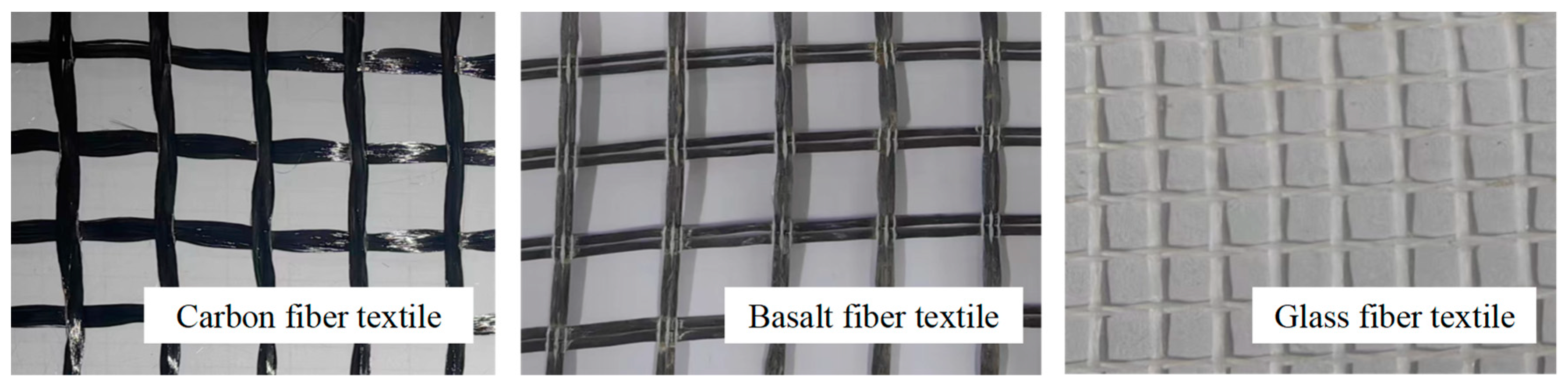
2.1.2. Fiber Textiles
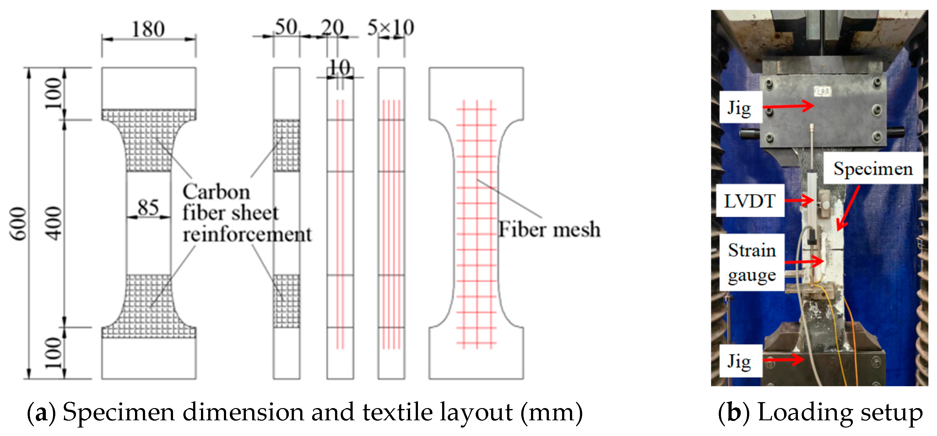
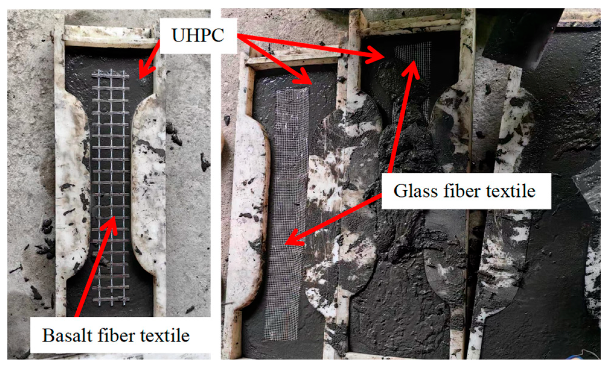
2.2. Specimen Manufacture Process and Experiment Program
2.3. Results and Analyses of Axial Tension Tests
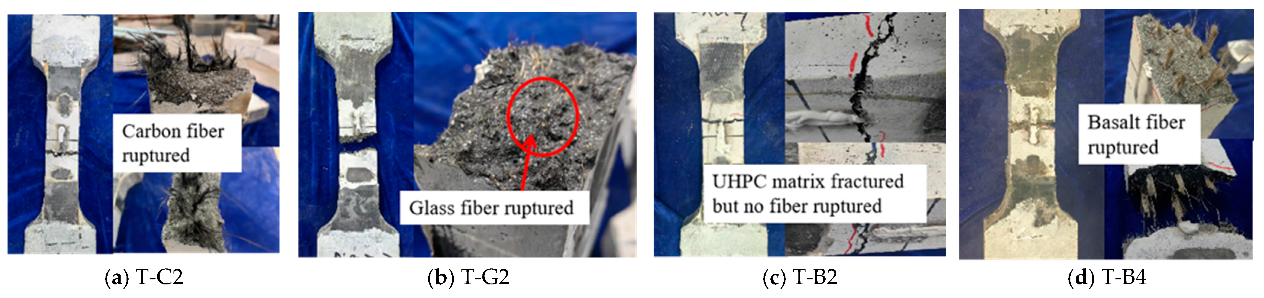
2.3.1. Failure Mode
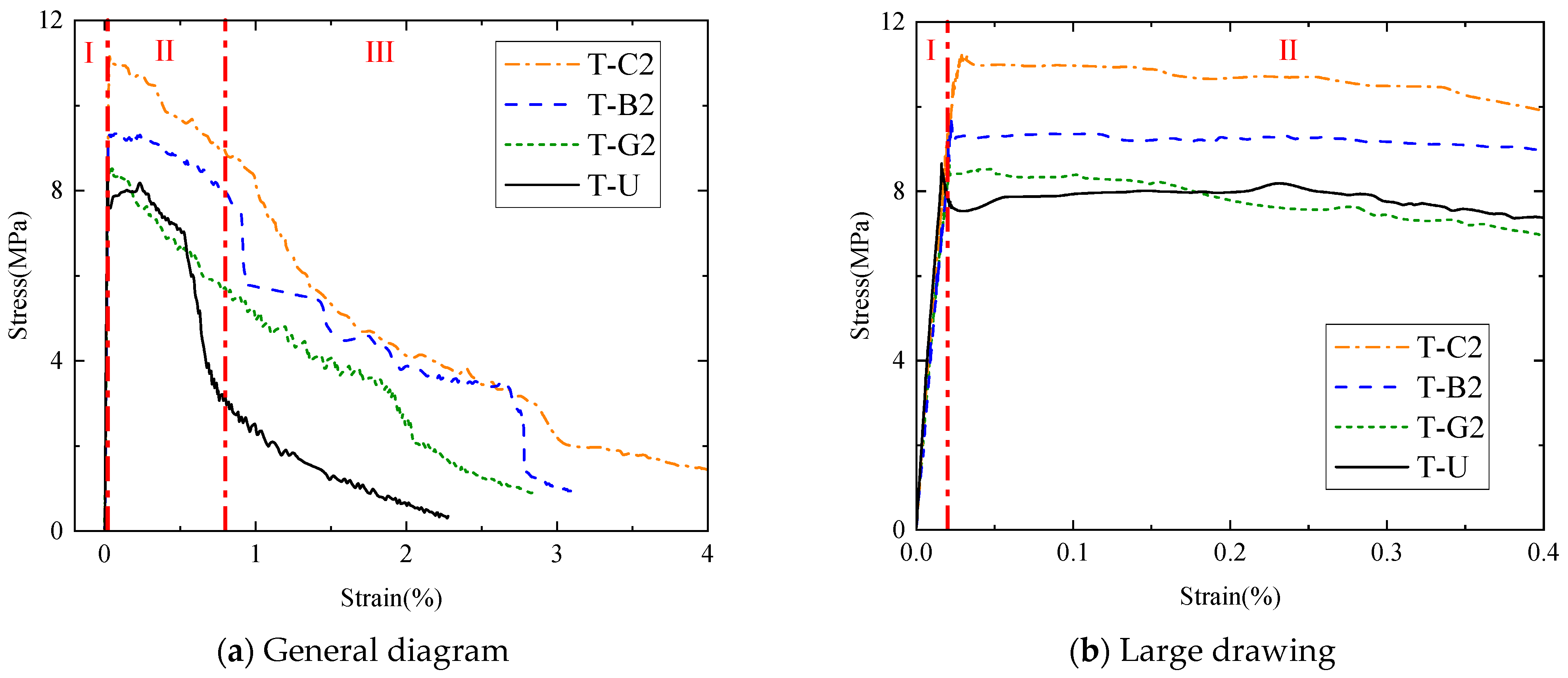
2.3.2. Impact of Fiber Type on Tensile Properties of TR-UHPC Composites
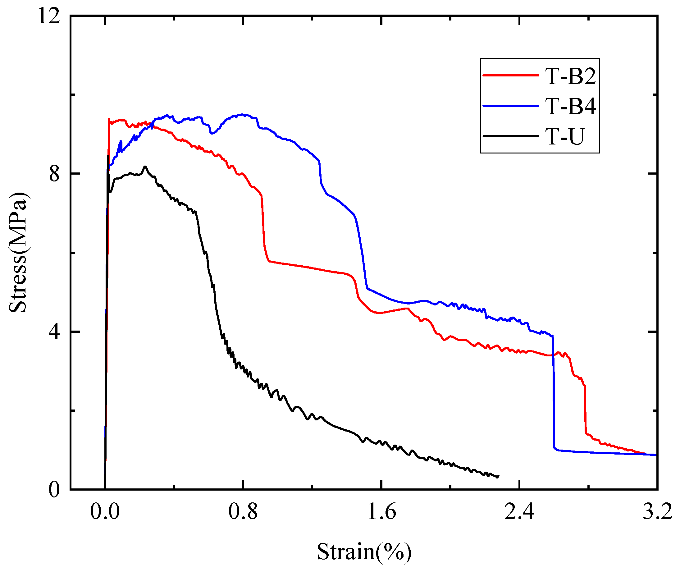
2.3.3. Impact of Textile Reinforcement Ratio on Tensile Properties of TR-UHPC Composites
3. Stacking and Bending Tests on BFT-UHPC Pedestrian Walkway Thin Slabs
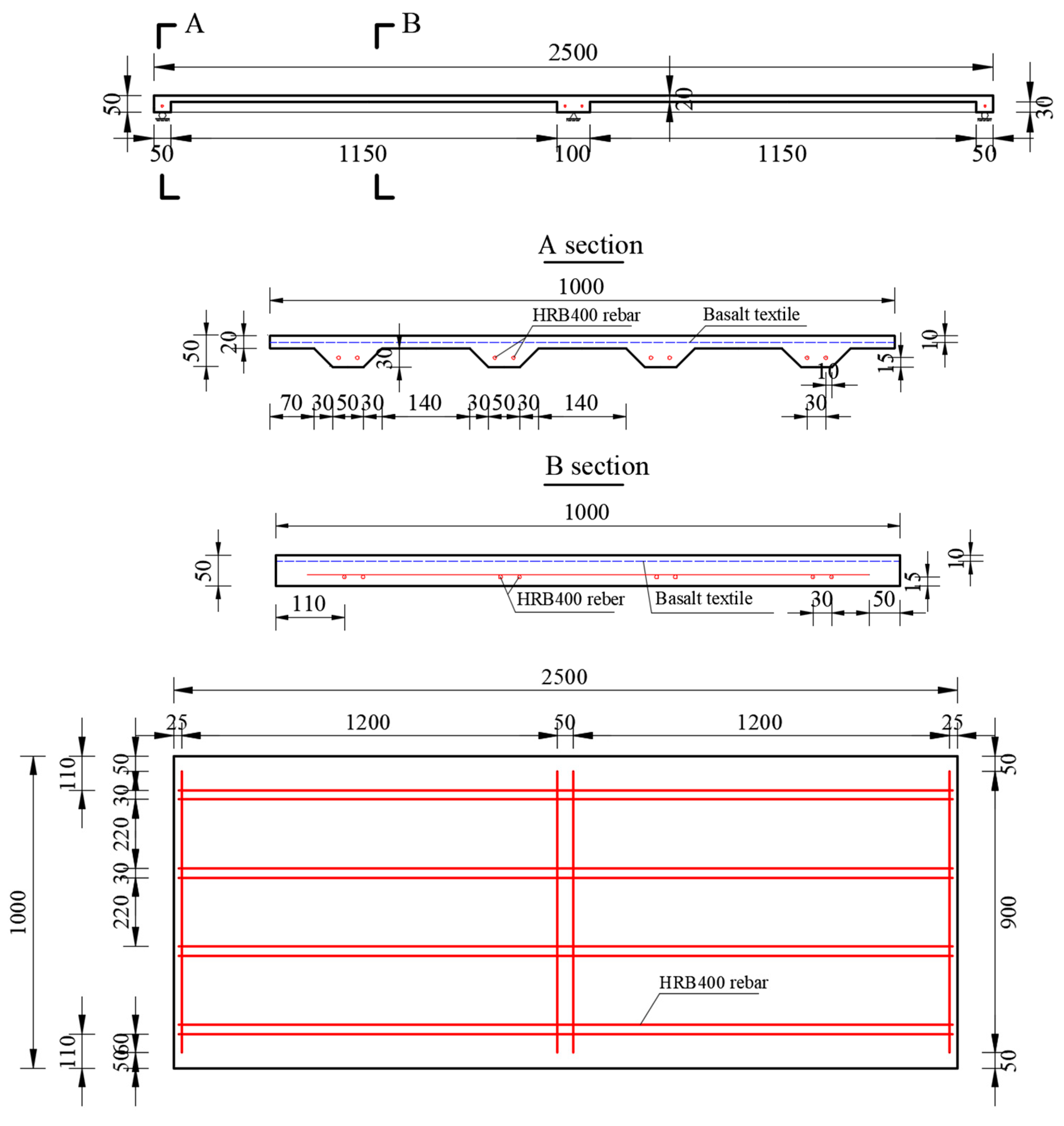
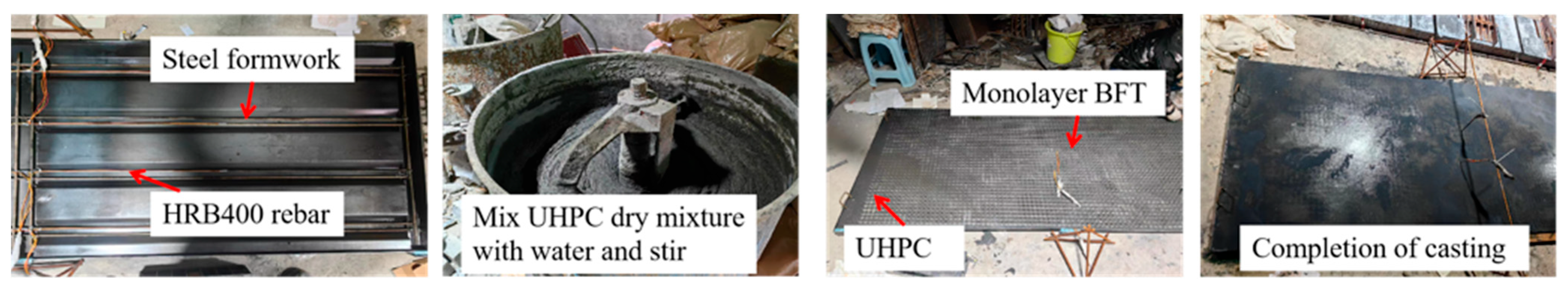
3.1. Design and Manufacture of Test Slab
3.2. Material
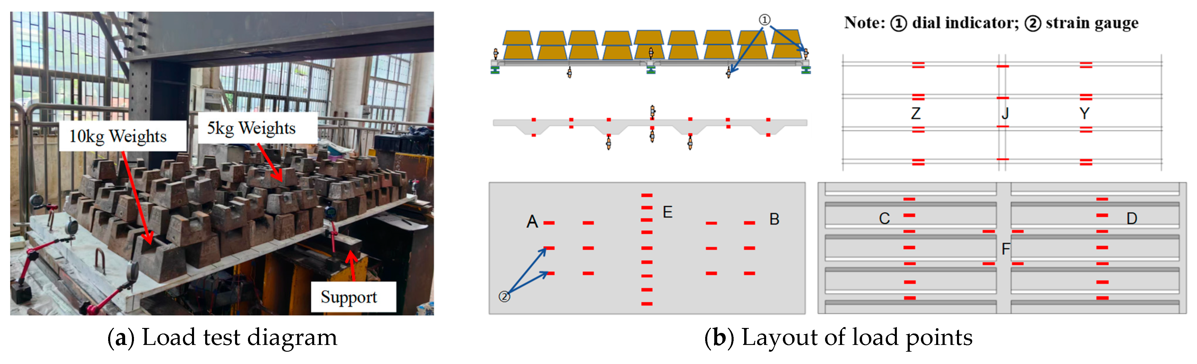
3.3. Stacking Test
3.3.1. Experiment Program
3.3.2. Test Results
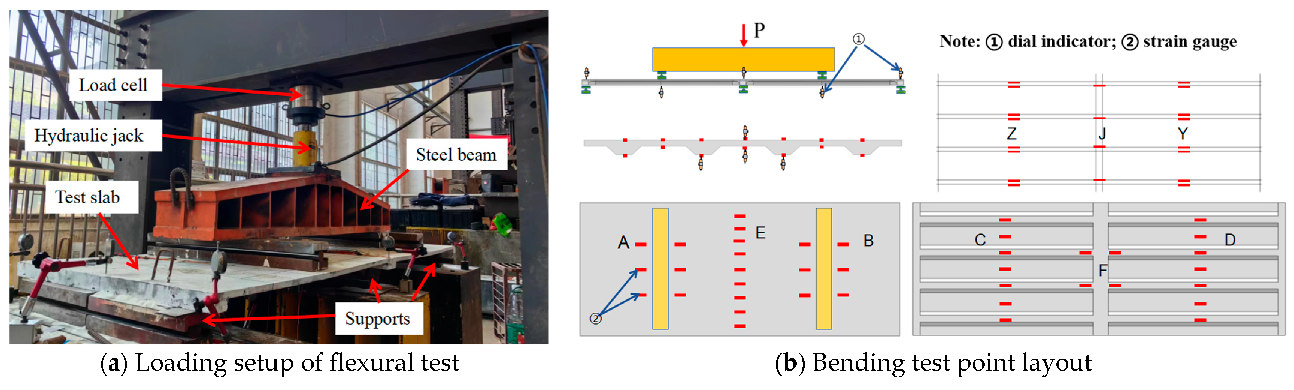
3.4. Bending Test
3.4.1. Experiment Program
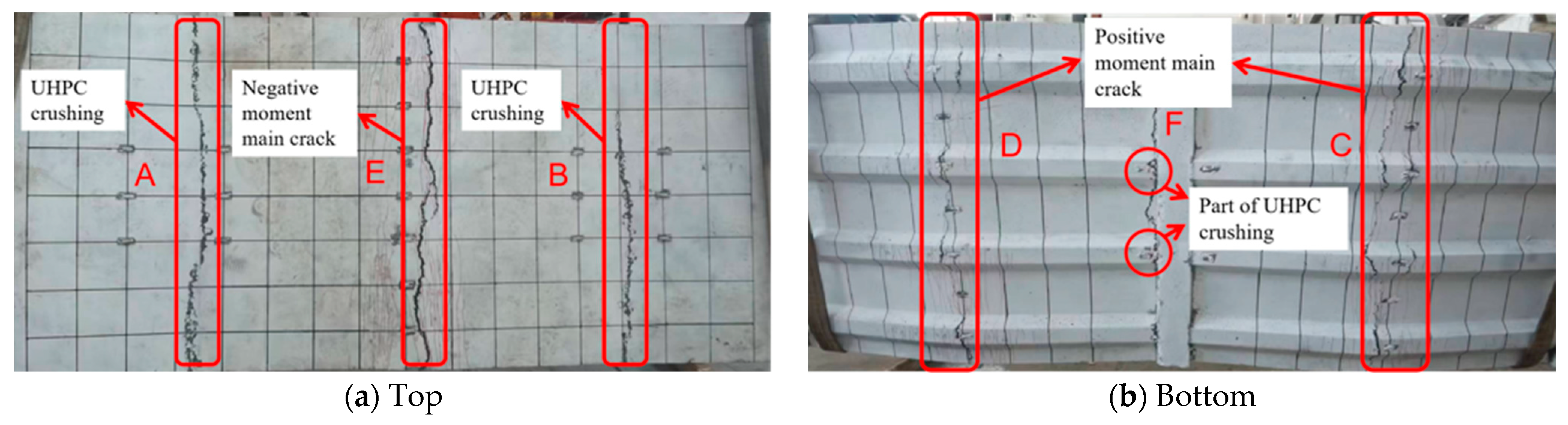
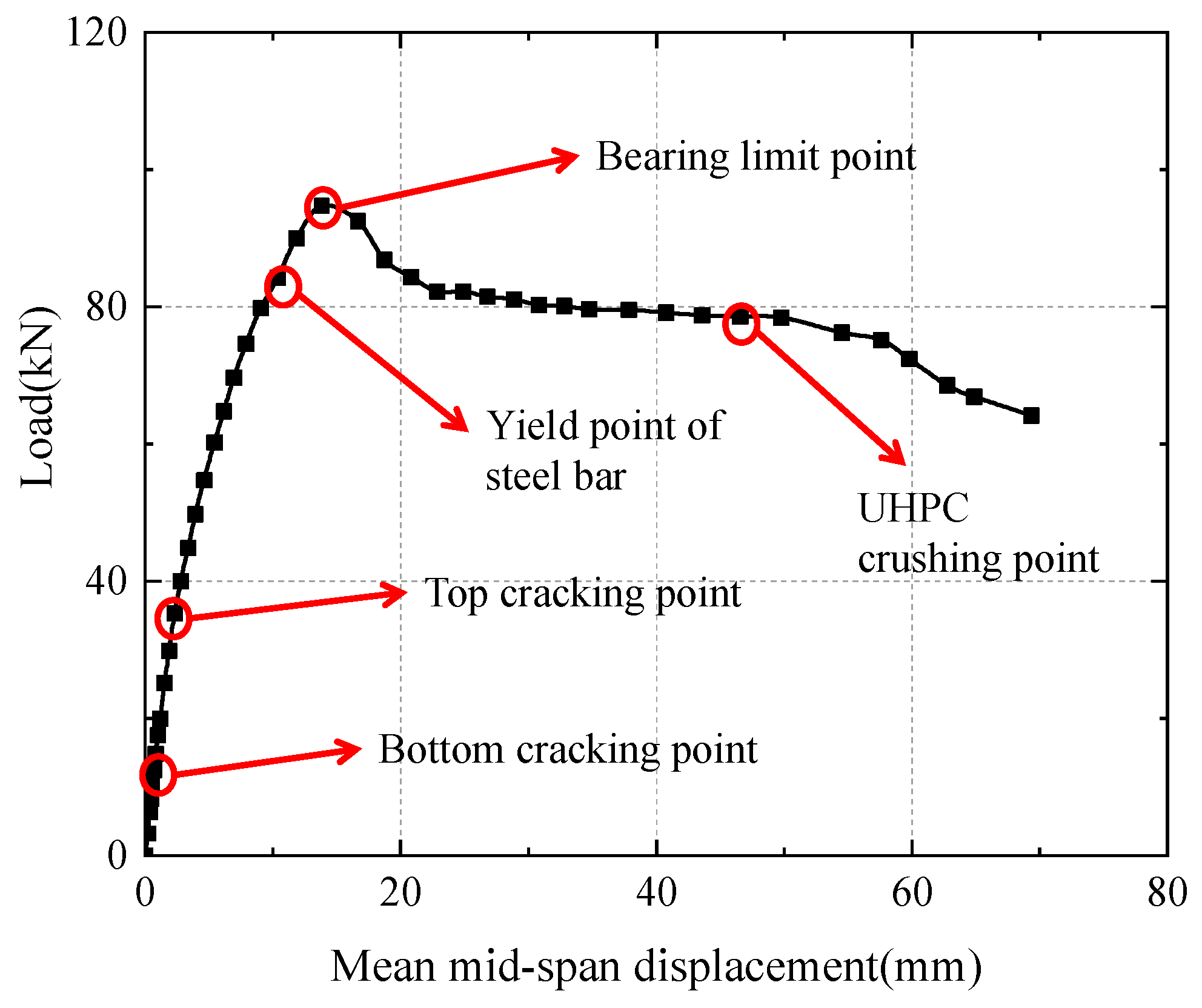
3.4.2. Failure Mode and Stiffness Analysis
3.4.3. Crack Width Development
4. Conclusions
- (1)
- In terms of the axial tensile performance, the fiber textiles ranked in the following order: CFT, BFT, and GFT. Furthermore, the corresponding increases in initial cracking strength and ultimate tensile strength were 18.0% and 21.9% for CFT, 12.0% and 16.0% for BFT, and only 9.1% and 8.0% for GFT, respectively.
- (2)
- When the textile reinforcement ratio was higher than the critical one, the specimen exhibited a clear strain hardening phenomenon after cracking. The T-B4 specimen showed a 12.0% increase in initial cracking strength and a 15.9% increase in tensile strength compared to the T-B2 specimen. The ultimate strain of T-B4 was 1.4 times that of T-B2 and 2.6 times that of the plain UHPC tensile specimen.
- (3)
- In the stacking test, the mid-span deflection of the BFT-UHPC slab was 0.775 mm under the crowd load (4 kN/m2), which was only 19.8% of the deflection limit, satisfying the walking comfort requirements of pedestrians. Therefore, the BFT-UHPC slab can remain uncracked during service.
- (4)
- The crack resistance and superior toughness of the BFT-UHPC composite have been well-verified. Fiber textiles play an important role in limiting the development of crack width, maintaining stiffness, and improving the ductility of the slab.
Author Contributions
Funding
Institutional Review Board Statement
Informed Consent Statement
Data Availability Statement
Acknowledgments
Conflicts of Interest
References
- Ministry of Transport. Ministry of Transport of the People’s Republic of China. Statistical Bulletin on the Development of Transport Industry in 2022. China Transportation Report, 2023-06-16 (002). 2022. Available online: https://xxgk.mot.gov.cn/2020/jigou/zhghs/202306/t20230615_3847023.html (accessed on 16 June 2023). (In Chinese)
- Shamsad, A. Reinforcement corrosion in concrete structures, its monitoring and service life prediction––A review. Cem. Concr. Compos. 2003, 25, 459–471. [Google Scholar]
- Andrade, C. Propagation of reinforcement corrosion: Principles, testing and modelling. Mater. Struct. 2019, 52, 1–26. [Google Scholar] [CrossRef]
- Kang, S.T.; Lee, Y.; Park, Y.D.; Kim, J.K. Tensile fracture properties of an ultra-high performance fibre reinforced concrete (UHPFRC) with steel fiber. Compos. Struct. 2010, 92, 61–71. [Google Scholar] [CrossRef]
- Tayeh, B.A.; Aadi, A.S.; Hilal, N.N.; Bakar, B.H.A.; Al-Tayeb, M.M.; Mansour, W.N. Properties of ultra-high performance fibre reinforced concrete (UHPFRC): A Review Paper. AIP Conf. Proc. 2019, 2157, 20040e1. [Google Scholar]
- Yang, K.; Long, G.; Tang, Z.; Wu, H.; Ma, G.; Cheng, Z.; Xiang, Y.; Xie, Y. Enhancement in strength and toughness of ultra-high performance concrete (UHPC) from micron- and nano-scale. J. Build. Eng. 2023, 69, 106308. [Google Scholar] [CrossRef]
- Li, J.; Wua, Z.; Shi, C.; Yuan, Q.; Zhang, Z. Durability of ultra-high performance concrete—A review. Constr. Build Mater 2020, 255, 119296. [Google Scholar] [CrossRef]
- Guo, Y.; Wang, J. Flexural behavior of high-strength steel bar reinforced UHPC beams with considering restrained shrinkage. Constr. Build. Mater. 2023, 409, 133802. [Google Scholar] [CrossRef]
- Lai, Y.; Li, Y.; Huang, M.; Zhao, L.; Chen, J.; Xie, Y.M. Conceptual design of long span steel-UHPC composite network arch bridge. Eng. Struct. 2023, 277, 115434. [Google Scholar] [CrossRef]
- CCPA-UHPC. 2022 China Ultra High Performance Concrete (UHPC) Technology and Application Development Report (Part II). Concr. World 2022, 170, 18–23. (In Chinese) [Google Scholar]
- Chen, B.; Wu, H.; An, M.l.; Lee, G.C. Application of ultra-high performance concrete in bridge engineering in China. In Proceedings of the International Interactive Symposium on Ultra-High Performance Concrete, Des Moines, IA, USA, 18–20 July 2016; Iowa State University Digital Press: Ames, IA, USA, 2016; Volume 1. [Google Scholar] [CrossRef]
- Joaquín, A.; Carvajal-Muñoz, J.S.; Ramírez-Munévar, C. Application of ultra-high-performance concrete as bridge pavement overlays: Literature review and case studies. Constr. Build. Mater. 2024, 410, 134221. [Google Scholar]
- Li, C.; Shi, Y.; Zhou, J.; Fang, C.; He, J.; He, L. Experimental investigation on UHPC shrinkage of full-scale steel-UHPC composite bridge deck. Dev. Built Environ. 2023, 16, 100281. [Google Scholar]
- Duan, Y.; Zhang, H.; Zhang, G.; Chen, P.; Li, X. Study on the Influence of Coupling Dynamic Performance of Rail-Railway Steel Truss Bridge. Railw. Stand. Des. 2024, 1–7. (In Chinese) [Google Scholar]
- Qiu, M.; Shao, X.; Wille, K.; Yan, B.; Wu, J. Experimental investigation on flexural behavior of reinforced ultra high performance concrete low-profile T-beams. Int. J. Concr. Struct. Mater. 2020, 14, 1–20. [Google Scholar] [CrossRef]
- JTG D62-2018; Code for Design of Reinforced Concrete and Prestressed Concrete Bridges and Culverts for Highway. China Communication Press: Beijing, China, 2018. (In Chinese)
- Song, L. Research on Application of ultra-high performance concrete in Bridge structure. Railw. Constr. Technol. 2022, 82–86. (In Chinese) [Google Scholar] [CrossRef]
- Chen, L. Design and Application of High Strength and High Toughness Cement-Based Composite Pavement cover for High-Speed Railway; Southwest Jiaotong University: Chengdu, China, 2018. (In Chinese) [Google Scholar]
- Ala, T.; Brisid Isufi Davood, M.; António, P. Flexural strengthening of flat slabs with FRP composites using EBR and EBROG methods. Eng. Struct. 2020, 211, 110483. [Google Scholar] [CrossRef]
- Kar, S.; Biswal, K. Hear strengthening of reinforced concrete T-Beams by using fiber-reinforced polymer com posites: A data analysis. Arab. J. Sci. Eng. 2020, 45, 4203–4234. [Google Scholar] [CrossRef]
- Zhai, M. Research on Mechanical Properties and Application of Textile-Reinforced UHPC Materials; Southeast University: Dhaka, Bangladesh, 2022. (In Chinese) [Google Scholar]
- Contamine, R.; Larbi, A.; Hamelin, P. Contribution to direct tensile testing of textile reinforced concrete (TRC) composites. Mater. Sci. Eng. A 2011, 528, 8589–8598. [Google Scholar] [CrossRef]
- Gong, T.; Ahmed, A.H.; Curosu, I.; Mechtcherine, V. Tensile behavior of hybrid fiber reinforced composites made of strain-hardening cement-based composites (SHCC) and carbon textile. Constr. Build. Mater. 2020, 262, 120913. [Google Scholar] [CrossRef]
- Dong, Z.; Dai, J.; Deng, M.; Wu, Z. Experimental study on the mechanical properties of textile reinforced mortar (TRM) composites with different yarn shapes subjected to uniaxial tension. Arch. Civil. Mech. Eng. 2022, 22, 185. [Google Scholar] [CrossRef]
- Meng, W.; Khayat, K.H.; Bao, Y. Flexural behaviors of fiber-reinforced polymer fabric reinforced ultra-high-performance concrete panels. Cem. Concr. Compos. 2018, 93, 43–53. [Google Scholar] [CrossRef]
- GB/T 50081-2019; Test Method Standard for Physical and Mechanical Properties of Concrete. China Architecture and Construction Press: Beijing, China, 2019; pp. 18–25. (In Chinese)
- GB/T 31387-2015; Reactive Powder Concrete. Standards Press of China: Beijing, China, 2015; pp. 8–9. (In Chinese)
- Zhou, Z.; Zhang, Y.; Wang, Y.; Han, F.; Tian, H.; Peng, Z. Experimental study on tensile mechanical properties of mesh-reinforced UHPC thin plates. J. Southeast Univ. (Nat. Sci. Ed.) 2019, 49, 611–617. (In Chinese) [Google Scholar]
- Hegger, J.; Will, N.; Bruckermann, O.; Voss, S. Load–bearing behaviour and simulation of textile reinforced concrete. Mater. Struct. 2006, 39, 765–776. [Google Scholar] [CrossRef]
- Banholzer, B.; Brockmann, T.; Brameshuber, W. Material and bonding characteristics for dimensioning and modelling of textile reinforced concrete (TRC) elements. Mater. Struct. 2006, 39, 749–763. [Google Scholar] [CrossRef]
- Xu, S.; Yan, Y.J. Axial tensile properties of concrete reinforced by fiber braided mesh with low distribution rate. Compos. Mater. 2011, 28, 206–213. (In Chinese) [Google Scholar]
- Tanarslan, H.; Alver, N.; Jahangiri, R.; Yalçınkaya, Ç.; Yazıcı, H. Flexural strengthening of RC beams using UHPFRC laminates: Bonding techniques and rebar addition. Eng. Struct. 2017, 155, 45–55. [Google Scholar] [CrossRef]
- Tanarslan, H. Flexural strengthening of RC beams with pretextileated ultra high performance fiber reinforced concrete laminates. Eng. Struct. 2017, 151, 337–348. [Google Scholar] [CrossRef]
- GB/T 228.1-2010; Standardization Administration of China. Tensile test of Metal Materials. Standards Press of China: Beijing, China, 2010. (In Chinese)
- JTGD60−2015; Industry Standard of the People’s Republic of China. General Code for Design of Highway Bridges and Culverts. People’s Communications Press Co., Ltd.: Beijing, China, 2015. (In Chinese)
- GB50010-2010; Ministry of Housing and Urban-Rural Development of the People’s Republic of China. Code for Design of Concrete Structures. China Building and Construction Press: Beijing, China, 2010. (In Chinese)


| Constituent | Cement | Silica Fume | Water Reducer | Fly Ash | Quartz Sand | Quartz Powder | Water | Water–Binder Ratio |
|---|---|---|---|---|---|---|---|---|
| Mass ratio | 1 | 0.25 | 0.2 | 0.1 | 1.1 | 0.25 | 0.243 | 0.18 |
| Materials | fcu/MPa | fc/MPa | ft/MPa | Ec/GPa |
|---|---|---|---|---|
| UHPC (Steam curing 48 h) | 143.4 | 128.94 | 7.96 | 42.50 |
| Textile Type | Grid Size (mm × mm) | Young’s Modulus (GPa) | Tensile Strength (MPa) | Ultimate Tensile Strain (%) | Single Bundle Sectional Area (mm2) |
|---|---|---|---|---|---|
| CFT | 20 × 20 | 230 | 3300 | 2.80 | 0.88 |
| GFT | 3 × 3 | 71 | 2204 | 1.98 | 0.16 |
| BFT | 25 × 25 | 80 | 2362 | 2.77 | 1.45 |
| Specimen | Fiber Type | Textile Layer Number | Textile Reinforcement Ratio |
|---|---|---|---|
| T-C2 | Carbon fiber | 2 | 0.20% |
| T-G2 | Glass fiber | 2 | 0.21% |
| T-B2/4 | Basalt fiber | 2/4 | 0.25%/0.50% |
| T-U | -- | -- | -- |
| Specimen Group | Initial Cracking Stress (MPa) | Initial Cracking Strain (με) | Peak Stress (MPa) | Peak Strain (με) |
|---|---|---|---|---|
| T-U | 7.48 (1.4%) | 144.5 (7.3%) | 7.96 (5.6%) | 164.3 (17.7%) |
| T-G2 | 8.16 (3.3%) | 182.4 (11.0%) | 8.60 (3.9%) | 222.3 (24.5%) |
| T-C2 | 8.83 (12.8%) | 213.3 (10.0%) | 9.69 (13.2%) | 254.3 (20.3%) |
| T-B2 | 8.38 (2.5%) | 190.5 (2.2%) | 9.23 (4.7%) | 233.8 (3.4%) |
| T-B4 | 8.57 (4.5%) | 181.7 (3.2%) | 9.80 (2.6%) | 8805.5 (15.8%) |
| Materials | fcu/MPa | fc/MPa | ft/MPa | Ec/GPa |
|---|---|---|---|---|
| UHPC (Steam curing) | 157.52 | 143.92 | 9.53 | 40.23 |
| Reinforcement Type | Diameter (mm) | Yield Strength (MPa) | Ultimate Strength (MPa) | Elasticity Modulus (GPa) |
|---|---|---|---|---|
| HRB400 | 8 | 429.3 | 590.3 | 200 |
| Loading Level | Loaded Weight (kg) | Uniform Load (kN/m2) | Mean Deflection at Mid-Span (mm) | The Mid-Span Bending Moment M (kN·m) |
|---|---|---|---|---|
| 0 | 0 | 0 | 0 | 0 |
| 1 | 250 | 1 | 0.156 | 0.219 |
| 2 | 500 | 2 | 0.321 | 0.441 |
| 3 | 750 | 3 | 0.459 | 0.658 |
| 4 | 1000 | 4 | 0.612 | 0.876 |
| 5 | 1250 | 5 | 0.775 | 1.096 |
| Eigenvalue | (kN) | (kN) | (kN) | (kN) | (kN) |
|---|---|---|---|---|---|
| Load | 14.8 | 84.2 | 92.4 | 84.2 | 94.7 |
| Load | 39.9 kN | 44.8 kN | 54.7 kN | 74.6 kN | 84.2 kN |
|---|---|---|---|---|---|
| Specimen crack width (mm) | 0.03 | 0.04 | 0.05 | 0.08 | 0.08 |
| Crack width of concrete slab (mm) | 0.05 | 0.06 | 0.11 | 0.15 | 0.23 |
Disclaimer/Publisher’s Note: The statements, opinions and data contained in all publications are solely those of the individual author(s) and contributor(s) and not of MDPI and/or the editor(s). MDPI and/or the editor(s) disclaim responsibility for any injury to people or property resulting from any ideas, methods, instructions or products referred to in the content. |
© 2024 by the authors. Licensee MDPI, Basel, Switzerland. This article is an open access article distributed under the terms and conditions of the Creative Commons Attribution (CC BY) license (https://creativecommons.org/licenses/by/4.0/).
Share and Cite
Fu, J.; Zhang, Y.; Qin, Y. Experimental Investigation of TR-UHPC Composites and Flexural Behavior of TR-UHPC Composite Slab. Appl. Sci. 2024, 14, 3161. https://doi.org/10.3390/app14083161
Fu J, Zhang Y, Qin Y. Experimental Investigation of TR-UHPC Composites and Flexural Behavior of TR-UHPC Composite Slab. Applied Sciences. 2024; 14(8):3161. https://doi.org/10.3390/app14083161
Chicago/Turabian StyleFu, Jiuzhi, Yang Zhang, and Yanyue Qin. 2024. "Experimental Investigation of TR-UHPC Composites and Flexural Behavior of TR-UHPC Composite Slab" Applied Sciences 14, no. 8: 3161. https://doi.org/10.3390/app14083161
APA StyleFu, J., Zhang, Y., & Qin, Y. (2024). Experimental Investigation of TR-UHPC Composites and Flexural Behavior of TR-UHPC Composite Slab. Applied Sciences, 14(8), 3161. https://doi.org/10.3390/app14083161