Article

Development and Application of Unsealed Borehole Leakage Detection Device Based on Flow Method

1
State Key Laboratory Cultivation Base for Gas Geology and Gas Control, Henan Polytechnic University, Jiaozuo 454000, China
2
State Collaborative Innovation Center of Coal Work Safety and Clean-Efficiency Utilization, Henan Polytechnic University, Jiaozuo 454000, China
3
The First Exploration Team of Shandong Coal Geology Bureau, Jinan 250000, China
4
Shandong Engineering Research Center of Mine Gas Disaster Prevention, Jinan 250000, China
*
Author to whom correspondence should be addressed.
Appl. Sci. 2024, 14(15), 6684; https://doi.org/10.3390/app14156684
Submission received: 3 June 2024 / Revised: 22 July 2024 / Accepted: 24 July 2024 / Published: 31 July 2024
(This article belongs to the Special Issue Advanced Methodology and Analysis in Coal Mine Gas Control)

Abstract

:
Poor sealing of gas extraction boreholes is one key to restrict gas extraction efficiency. In this paper, a novel borehole sealed quality detection device for the gas extraction of a coal mine is developed based on the theory of air leakage. By comparing the amount of gas extracted at different test points, it is possible to determine whether there is air leakage around the borehole, and the specific leakage position and leakage amount. Moreover, this device has the advantages of simple operation and a short test period. Based on the above analysis, a corresponding air leakage disposal method was proposed to handle the leaky boreholes. Field tests showed that the air–gas mixture flow in the test borehole was reduced by a factor of approximately 1.55 and the concentration of pure seam gas was increased approximately six times after the disposal of the air leaks. The combination of the leakage disposal method and the leakage detection device can accurately seal the borehole at the position of the leak, thus effectively ensuring the effectiveness of gas extraction from the borehole. The findings have important implications for improving the efficiency of gas extraction in coal mining operations.

1. Introduction

Coal mines in China generally have the occurrence characteristics of complex geological conditions, high gas content, and high gas pressure in coal seams, which make China one of the countries with serious coal and gas outburst accidents in the world [1,2,3,4]. Gas accidents account for more than 70 percent of major accidents in China’s coal mines, according to statistics. Therefore, controlling the occurrence of gas accidents in coal mines is key to ensuring the safety of coal mine production. Years of coal mining practices have shown that gas extraction is an effective means of controlling coal mine gas disasters [5,6,7,8,9,10].
Ensuring the quality of borehole sealing is the key to improve the effectiveness of borehole gas extraction [11,12]. Currently, the commonly used sealing methods for drainage boreholes are the normal pressure sealing method and pressure sealing method. Normal pressure sealing methods mainly include polyurethane sealing, cement mortar sealing, and polyurethane–cement mortar joint sealing. Although this sealing method has a small investment, and simple equipment and process, the high polyurethane foaming ratio enables rapid sealing. But the cement mortar is naturally pumped without loading high pressure, the slurry penetration range is small, and the sealing effectiveness is not good for the surrounding rock when there are a large number of cracks [13,14,15,16]. Pressure sealing is mainly the bag type “two plugging and one injection” slurry (mucus) pressure sealing method. This sealing method achieves grouting of the borehole walls, which can effectively seal the cracks around the borehole well, and support the borehole after the slurry is consolidated. However, there are also problems such as high cost, complicated operation, and grout pressure being limited by the strength of the bag. Considering that the sealing quality of boreholes can be better guaranteed with the pressure sealing method under different conditions, most coal mines adopt the “two plugging and one injection” method of pressure sealing [17,18,19].
However, no matter which sealing method is used, air leakage will occur in the actual extraction process [20,21]. In general, the causes of unsealed borehole leakage are mainly reflected in the following aspects. First of all, when the sealing length is insufficient, the sealing section of the borehole may be in the range of the pressure relief area, which is an area of more developed cracks, permeability, and proneness to air leakage [22,23,24,25,26]. Secondly, when the sealing material is deformed or destroyed under the action of borehole deformation and its own gravity, there will be leakage from the sealing material itself or the contact surface between the material and the borehole wall [27,28]. Moreover, under the mutual superposition of double fracture area of the roadway fracture area and the fracture area around the borehole, the fractures around the borehole are developed and penetrated into each other, forming a macroscopic air leakage channel, thus affecting the sealing quality of the borehole [29].
The detection of leaky boreholes is a prerequisite for the disposal of air leaks and the improvement in the quality of borehole sealing. This has also been studied extensively by a number of scholars. Liu et al. [22], Chen et al. [26], Zhang et al. [30], and Zhang et al. [31] revealed the effect of sealing depth, extraction negative pressure, borehole diameter, and coal permeability on the quality of borehole sealing by establishing different borehole leakage models. Ba [32], Fan et al. [33], and Wang et al. [34] developed the air leakage detection device for gas extraction boreholes based on the distribution law and changes in gas concentration and extraction negative pressure in leaky boreholes, and the sealing quality of gas extraction boreholes was determined by detecting the gas sample parameters of different borehole depths. Qi et al. [35] and Cai et al. [36] injected tracer gas into the borehole, and then used the tracer gas concentration sensor to detect the tracer gas concentration in the extracted gas, so as to judge the sealing quality of the extraction borehole.
In summary, the air leakage detection of unsealed boreholes is crucial for enhancing the effectiveness of gas extraction. However, while the leakage detection methods and techniques proposed by scholars are effective, the detection period is generally long and the testing process is cumbersome. Therefore, there is an urgent need to develop new unsealed borehole leakage detection technologies to enable the rapid and efficient detection of air leakage around boreholes. In this paper, a flow-based technique was proposed for unsealed borehole leakage detection, which focuses on accurately determining the specific leakage position based on the flow variations at different locations in the borehole. On the one hand, this technique inherits the advantages of previous air leakage detection techniques. On the other hand, it makes up for their shortcomings. The results of this paper have positive implications for improving the gas extraction effectiveness of boreholes and ensuring gas extraction rates in mines.

2. Research and Development of Unsealed Borehole Leakage Detection Technology Based on Flow Method

2.1. Components of Air Leakage Detection Device

Most of the previous leakage detection is based on judging the concentration of seam gas extracted and negative pressure to determine whether the borehole is leaking. In this paper, a flow-based device was proposed for unsealed borehole leakage detection. The device (Figure 1) includes mainly a pressure limiting valve, pressure gauge, connecting rod, expandable capsule, sealing rubber plug, wet flow gauge, and other components. The specific leakage position and leakage amount can be judged based on the variation in the flow rate at different measurement points.
The specific operation of the leakage detection device is as follows.
(1)
Remove the original connection device of the extraction pipe from the borehole, and the expanding capsule is then pushed to measurement point 1 using a connecting rod;
(2)
Pass the outermost connection rod and the purple copper pipe (connected to wet flow gauge) through the double-hole rubber plug, and completely seal with the extraction pipe;
(3)
After all components are connected, open the underway press-air system to inflate the expanding capsule to seal the section of the borehole to be tested for leakage;
(4)
After the inflation is completed, open the extraction system valve, and observe the number of wet flow gauges;
(5)
When the number of wet flow gauges is stable (the number remains unchanged within 3 min), turn off the extraction system valve, and deflate and depressurize the expanding capsule. Then, send the expanding capsule to the next measurement point for the next set of flow tests by mounting a link.

2.2. Selection of the Main Components of the Air Leakage Detection Device

The air leakage detection device developed is mainly to determine the leakage position around the borehole by detecting the difference of extraction flow before and after the leakage position. This section focuses on the selection process of the main components of the device on the ground, including the selection of expandable capsules, pressure limiting valve, and flow gauge.

2.2.1. Expandable Capsule Pressure-Bearing Test

As the main component of the air leakage detection device, the pressure-bearing capacity of the expandable capsule determines the usefulness and reliability of the device. The main material of the expandable capsule selected in this device is polyurethane resin; it has the characteristics of a light weight, corrosion resistance, and strong plasticity, which make the expandable capsule suitable for boreholes of any aperture and angle, and also improve the pressure-bearing capacity and service life of the capsule. Meanwhile, in order to avoid rupture of the expandable capsule during the operation of the device, it is necessary to simulate and investigate the maximum pressure that the expandable capsule can withstand in the borehole. The specific steps are as follows. After the expandable capsule is sent into the Φ94 mm PVC pipe (consistent with the diameter of the commonly downhole borehole), slowly inflate the expandable capsule to observe the final rupture pressure of the capsule. In order to prevent the contingency of the structure, repeat the steps three times, and the rupture pressures of the selected expandable capsule are tested to be 0.40 MPa, 0.43 MPa, and 0.45 MPa, respectively (Figure 2). According to the test results, the pressure in the expandable capsule should be controlled below 0.4 MPa.

2.2.2. Tightness Test of Expandable Capsule

In order to determine the tightness of the selected capsule, relevant tests were also carried out (Figure 3). The specific steps are as follows. Put the capsule into the middle of the Φ94 mm PVC pipe, and fill it with water with a pressure of 0.2 MPa~0.4 MPa to fully expand the capsule. The CH4 gas with a pressure of 0.2 MPa then fills the PVC pipe sealed by the capsule. If the pressure inside the pipe remains constant for 20 min, it proves that the expandable capsule is well airtight. According to the test results, the tightness of the selected capsule is in accordance with the requirements.

2.2.3. Selection of Pressure Limiting Valve

The expandable capsule is inflated through the underground press-air system, and the expansion of the capsule generally requires a gas charge in excess of 0.1 MPa. The pressure of the underground press-air system in coal mines is generally 0.6~0.8 MPa. Since the selected capsule can withstand a maximum pressure of 0.4 MPa, in order to prevent the capsule from rupturing directly after it is connected to the press-air system, a pressure limiting valve (Figure 4) needs to be installed between the press-air system and the connecting rod equipped with the expandable capsule. In order to keep a certain affluence coefficient, the final selection of the pressure limiting valve pressure is 0.25 MPa.

2.2.4. Selection of Flow Gauge

This device determines the position of air leakage based on changes in the flow of air–gas mixture extracted from the borehole, so the choice of flow gauge is critical. Gas meters, rotors, and other flow gauges are mostly used to test gas flow in a barotropic environment. Considering that the flow gauges used in gas extraction are mostly under negative pressure conditions, after substantive investigations and selections, the wet flow gauge that can be used in the negative pressure environment of underground gas extraction is selected for this device. The specific model of the flow gauge can be chosen according to the actual working conditions of the coal mine.

2.3. Detection Principle of Leakage Detection Device

When the location of the expandable capsule is located at measurement point 1 in Figure 1, the first enclosed space is formed between the expandable capsule and the grout-sealed section, and the length of the first enclosed space is L1. The flow measured at this time is called Q11, and Q11 = Q1 + Q2, since Q1 is the pure seam gas flow extracted by the first enclosed space; Q2 is the amount of air leakage from the grout seal section. If the seal is intact, the flow measured in the first enclosed space is the pure seam gas flow Q1.
When the location of the expandable capsule is located at measurement point 2 in Figure 1, the second enclosed space is formed between the expandable capsule and the grout-sealed section, and the length of the second enclosed space is L2. The flow measured at this time is called Q22, and Q22 = Q′1 + Q2. This is since Q′1 is the seam gas flow extracted by the second enclosed space. If the seal is intact, the flow rate measured in the second enclosed space is the pure seam gas flow Q′1.
The two measurements were subtracted to obtain
Δ Q = Q 22     Q 11 = ( Q 1   +   Q 2 ) ( Q 1   +   Q 2 ) = Q 1     Q 1
where ΔQ is the flow corresponding to the length of the L2-L1, and thus the flow rate per unit length of borehole QE is obtained:
Q E = ( Q 1     Q 1 ) / ( L 2     L 1 )
Then, Q 1 = Q E L 1 , and then obtain
Q 2   =   Q 11     Q 1 = Q 11     Q E L 1
Based on the magnitude of Q2, it is possible to determine not only whether there are air leaks in the sealed section of the borehole, but also to obtain a specific value for the amount of leakage.
According to the theory of air leakage around boreholes, if there is no leakage in the detected L1 and L2 sections, the increase in the flow rate between the first and second measurement points is only the pure seam gas extraction in the tested section ΔL (the length of L2–L1); the increment of ΔQ (the flow rate corresponding to the length of L2–L1) will be very small, as shown in Figure 5a. If there is a leakage in the test section ΔL, the increment of ΔQ will be larger when the expandable capsule is tested at measurement point 2, as shown in Figure 5b. Due to the complex and variable extraction conditions in coal mines, a complete absence of air leakage rarely exists. Generally, when the ratio of the ΔQ to the flow measured at the previous point is less than 5%, consider the measured borehole to be in a non-leakage state, and when this ratio is greater than 30%, the borehole is leaking.

3. Results and Discussions

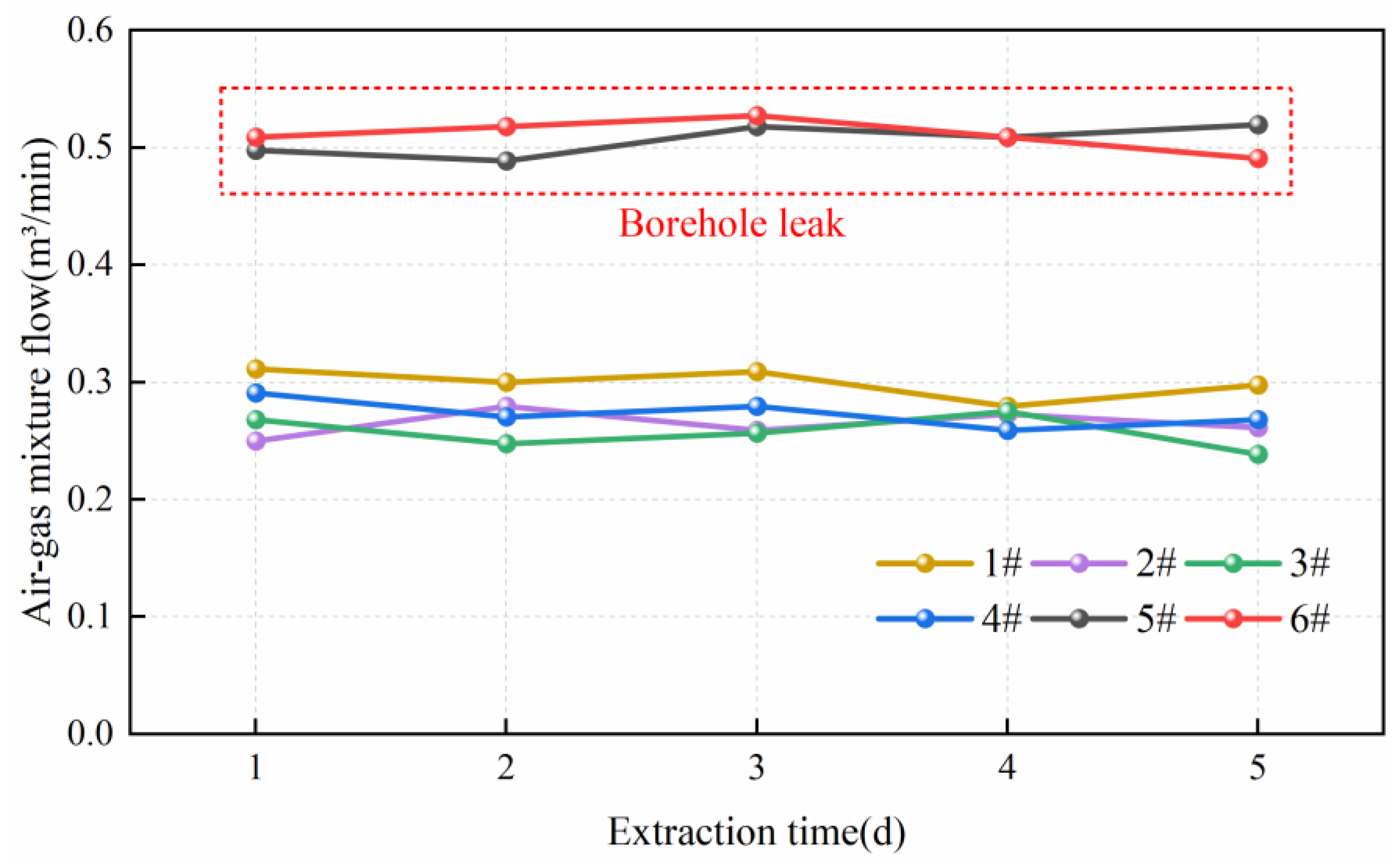
3.1. Field Application of Air Leakage Detection Technique

The soundness of the developed air leakage detection device was verified through field tests. The field site was selected at the 12,316 working face of Wangjialing Coal Mine in Shanxi Province, China, and the test site was selected at 850 m of the return airway in the 12,316 working face, with a total of six boreholes named borehole 1–borehole 6 and a test borehole length of 40 m. According to previous studies [26] and combined with the parameters of Wangjialing mine coal formation, the plastic area extent of the return airway in the 12,316 working face is 6 m. Therefore, seal the 1#–6# boreholes by the method of “two plugging and one injection”; the initial sealing depth of the borehole is 6 m and the depth of the sealing section is 6 m. The borehole spacing is set to 5 m based on the extraction radius of the test face.
After the boreholes are constructed, the extraction system is connected and the negative pressure 15 kPa is debugged; then, detect the changes in the air–gas mixture flow from boreholes by a wet flow gauge under the condition of constant negative pressure every day, as shown in Figure 6.
According to Figure 6, the 5# and 6# boreholes extract significantly more mixed flow than the other boreholes compared to the 1#, 2#, 3#, and 4# boreholes in the previous five days. It is assumed that there is leakage around 5 # and 6 # boreholes.
For the detection of the 6# borehole, the expanding capsule was initially lowered to 7.5 m with almost no flow at a negative pressure of 15 kPa. When the capsule was placed at 8 m for the second detection, the flow of air–gas mixture extracted reached 0.2 m3/min at a negative pressure of 15 kPa. When the capsule was placed at 8.5 m for the third detection, the flow of air–gas mixture extracted reached 0.4 m3/min. However, when the capsule was placed at 9 m for the fourth detection, the flow of air–gas mixture extracted reached 0.4008 m3/min. Therefore, the leakage position can be judged to be between 7.5 m and 8.5 m. The same method was used to detect the leakage position of the 5# borehole; it was concluded that the position of the air leaks of the 5# borehole was approximately between 8 and 9 m.

3.2. Air Leakage Disposal Technique

3.2.1. Principle of Air Leakage Disposal Technique

When using the air leakage detection device described above to detect a test borehole, it is necessary to provide secondary sealing to the borehole if there are air leaks inside. Currently, most approaches for addressing air leakage around boreholes are primarily based on the “three plugging and two injection” technique. This approach involves pre-judging potential air leakage locations based on “two plugging and one injection”, while reserving a bag in advance. During drilling and mining operations, the bag can be activated to perform secondary sealing if the concentration of seam gas extracted decreases. This approach has the disadvantage that air leakage disposal cannot achieve precise positioning and higher sealing costs [37,38]. In view of the shortcomings, this paper proposes the Φ10 mm sealing capsular bag secondary sealing method, which directly sends the secondary sealing capsular bag to the front end of the air leakage position. This method achieves precise disposal of the leakage position and reduces the cost of sealing boreholes.
The specific usage is as follows. Firstly, the conventional “two plugging and one injection” sealing method is used to perform the primary sealing to the extraction borehole, and observe the changes in the flow rate and concentration; if there is an increase in the flow rate and a decrease in the concentration, the borehole is tentatively judged to be leaking. Then, use the air leakage detection device to detect the leakage, as shown in Figure 1, after accurately determining the leakage position; a 10 mm diameter extraction pipe with a capsular bag of sealing holes is passed through the Φ50 mm extraction pipe commonly used in the borehole to the front end of the leakage position for secondary grouting and sealing. After secondary sealing, the diameter of the extraction pipe was changed from the original 50 mm to 10 mm. The principle of the secondary sealing of a Φ10 mm sealing capsular bag is shown in Figure 7.

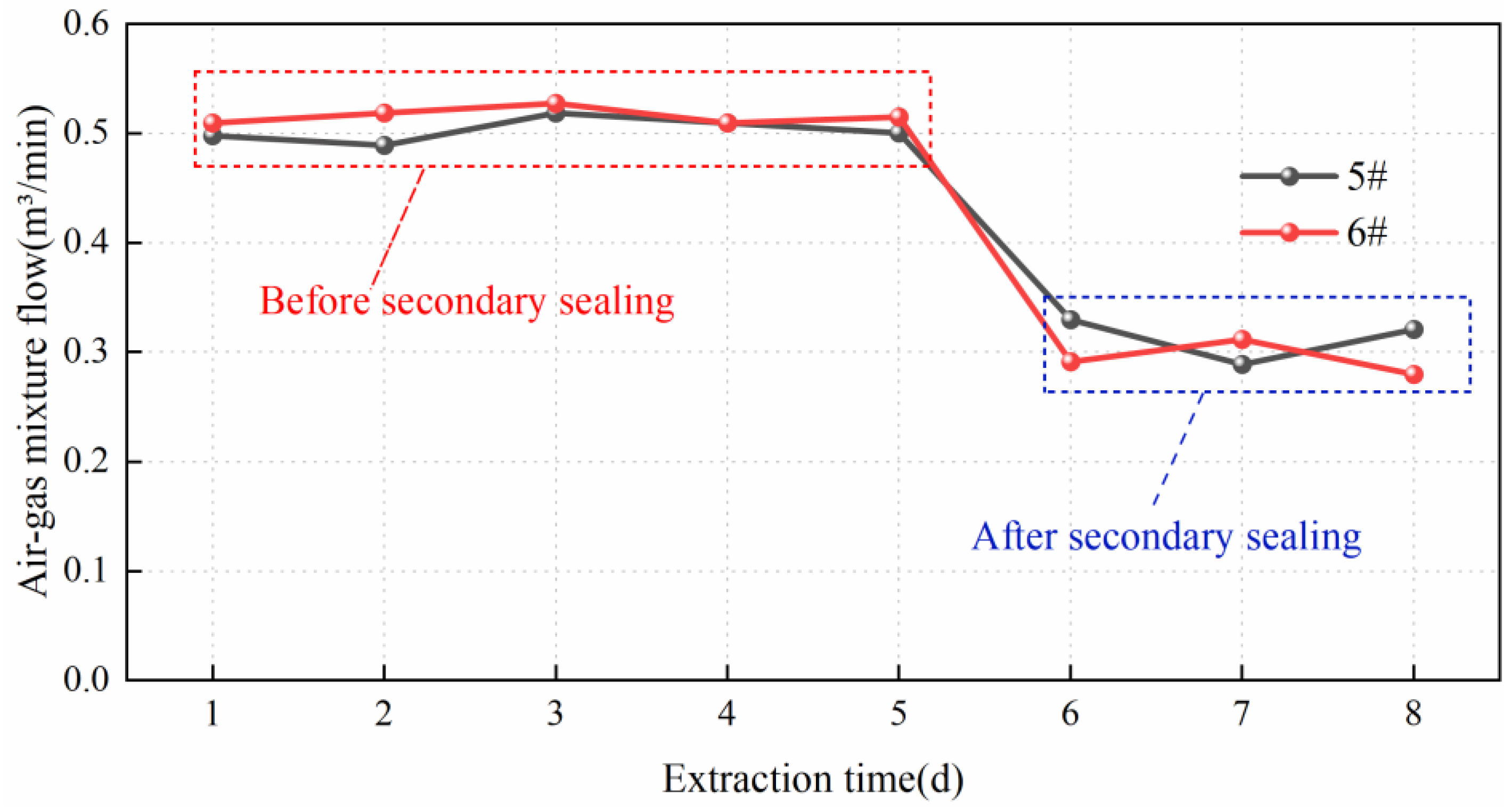
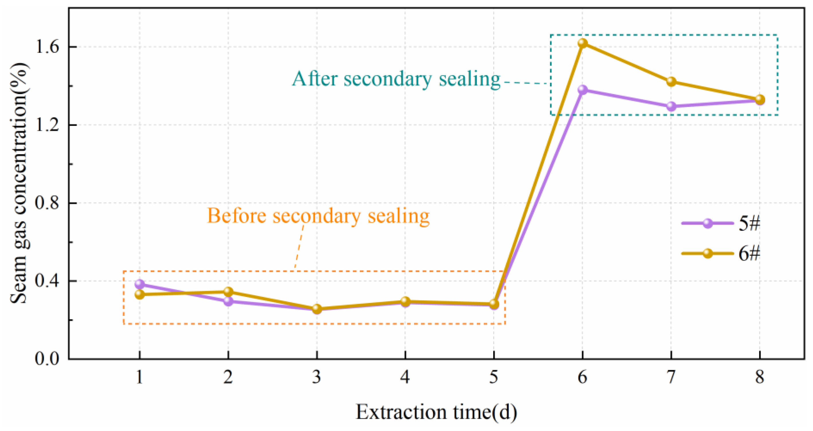
3.2.2. Leakage Disposal Effect

After detecting the specific leakage locations of the 5# and 6# boreholes with the new air leakage detection device proposed in this study, the above-mentioned Φ10 mm sealing capsular bag secondary sealing method is used for leakage disposal. After detecting the air–gas mixture flow before and after the secondary sealing, the changes in the seam gas concentration in the mixture were detected by the optical gas detector. The specific detection process of the optical gas detector is as follows.
(1)
Preparation: Check the detector chemical reactants, gas sample channel, and air tightness of the suction ball to confirm its good performance. The chemical reactants include the calcium chloride, silica gel, and sodium lime to make sure that they are not invalid. Then, check whether the gas sample channel and suction ball are leaking.
(2)
Zeroing: Place the instrument in air, and pinch and release the suction ball several times to ensure that the zero scale of the micro-reading disk (decimal display disk) coincides with the pointer and that the selected black baseline coincides with the zero position of the dividing plate (integer display panel).
(3)
Measurement: Extend the rubber tube connected to the air inlet to the air–gas mixture extracted, press the suction ball for more than 10 times, and ensure that the gas to be measured enters the gas chamber. Press the light source electric gate and observe the position of the black baseline and pointer from the eyepiece. Read out the integer number shown on the dividing plate and the decimal number shown on the micro-reading disk; the sum of the two is the measured gas concentration.
The seam gas concentration was tested for 8 days in 5# and 6# boreholes following the above testing process. The changes in the air–gas mixture flow and seam gas concentration in the mixture before and after the secondary sealing are shown in Figure 8 and Figure 9.
From the 5th day, the Φ10 mm sealing capsular bag method was carried out to seal the 5# and 6# leaky boreholes for the secondary sealing. It can be seen from Figure 8 that before the disposal of the leakage around the 5# and 6# boreholes, the air–gas mixture flow was as high as 0.51 m3/min. After the secondary sealing of 5# and 6# boreholes by the Φ10 mm sealing capsular bag method, the air–gas mixture flow decreased to 0.33 m3/min and 0.29 m3/min, respectively, which was decreased by a factor of approximately 1.55 and similar to other boreholes. The seam gas concentration in the air–gas mixture in 5# and 6# boreholes was improved by six times after the secondary sealing, as shown in Figure 9, which shows the significant increase in gas extraction efficiency.
Compared with the traditional method of “three plugging and two injection”, the air leakage disposal method proposed in this paper avoids the blindness of the secondary sealing. It can also accurately seal boreholes at the position of leaks, which saves the cost of sealing boreholes in mines and effectively ensures the effectiveness of gas extraction from boreholes.

4. Conclusions

In this paper, a new unsealed extraction borehole leakage detection technique and a corresponding air leakage disposal method were proposed with the aim of improving gas extraction levels in mines, reducing gas emissions, and enhancing gas resource utilization. The following conclusions were drawn from this study.
(1)
A new type of air leakage detection device for borehole gas extraction in coal mines has been developed to address the problem of a more cumbersome operation and longer testing period of the existing air leakage detection devices. By comparing the flow of gas extracted at different test points, it is possible to determine whether there is air leakage around the borehole, and the specific leakage position and leakage amount. This device has the advantages of simple operation and a short test period.
(2)
In view of the shortcomings of the “three plugging and two injection” secondary sealing technique, this paper proposes the Φ10 mm sealing capsular bag secondary sealing method. Field tests showed that the air–gas mixture flow in the test borehole was reduced by a factor of approximately 1.55 and the concentration of pure seam gas was increased approximately six times after the disposal of the leaky position.
(3)
The combination of the leakage disposal method and the leakage detection device can accurately seal the unsealed borehole at the position of the leak, thus avoiding the blindness of secondary sealing, reducing the cost of sealing boreholes, and effectively ensuring the effectiveness of gas extraction from the borehole.

Author Contributions

Conceptualization, Q.H. and H.C.; Methodology, Q.H., H.C. and X.C.; Software, Q.H. and K.A.; Formal analysis, Q.H. and Z.W.; Data curation, Y.Y. and G.X.; Validation, Y.Y. and G.X.; Supervision, H.C., Y.Y. and X.C.; Writing—original draft, Q.H. and H.C.; Writing—review and editing, Q.H., H.C. and Y.Y.; Project administration, Y.Y. and G.X.; Funding acquisition, H.C. All authors have read and agreed to the published version of the manuscript.

Funding

This work is financially supported by the Scientific and Technological Breakthrough Project of Henan Province (242102321030), the Henan Provincial Natural Science Foundation (242300421651 and 242300421012), the Innovation and Entrepreneurship Training Program for College Students (202210460028), the Fundamental Research Funds for the Universities of Henan Province (NSFRF230401), the Safety Discipline “double first-class” Creation Project of Henan Polytechnic University (AQ20230713 and AQ20230305), the Innovative Research Team in University of Henan Province (24IRTSTHN013), the Research Fund of Shandong Coalfield Geological Bureau (2022-004), and the Innovation Training Program of Henan Polytechnic University (202310460098).

Institutional Review Board Statement

Not applicable.

Informed Consent Statement

Not applicable.

Data Availability Statement

All data used to support the findings of this study are available from the corresponding author upon request.

Conflicts of Interest

The authors declare no conflict of interest.

References

  1. Nie, B.; Sun, S.J. Thermal recovery of coalbed methane: Modeling of heat and mass transfer in wellbores. Energy 2023, 263, 125899. [Google Scholar] [CrossRef]
  2. Yan, F.; Xu, J.; Peng, S.J.; Zou, Q.J.; Li, Q.G.; Long, K.; Zhao, Z.G. Effect of capacitance on physicochemical evolution characteristics of bituminous coal treated by high-voltage electric pulses. Powder Technol. 2020, 367, 47–55. [Google Scholar] [CrossRef]
  3. Kong, B.; Wang, E.Y.; Lu, W.; Li, Z.H. Application of electromagnetic radiation detection in high-temperature anomalous areas experiencing coalfield fires. Energy 2019, 189, 116144. [Google Scholar] [CrossRef]
  4. Kang, Y.S.; Huangfu, Y.H.; Zhang, B.; He, Z.P.; Jiang, S.Y.; Ma, Y.Z. Gas oversaturation in deep coals and its implications for coal bed methane development: A case study in Linxing Block, Ordos Basin, China. Front. Earth Sci. 2023, 10, 1031493. [Google Scholar] [CrossRef]
  5. Tang, S.L.; Zhai, H.B.; Tang, H.; Yang, F. Isothermal desorption hysteretic model for deep coalbed methane development. Geofluids 2022, 2022, 5259115. [Google Scholar] [CrossRef]
  6. Li, H.Y.; Lau, H.C.; Huang, S. China’s coalbed methane development: A review of the challenges and opportunities in subsurface and surface engineering. J. Pet. Sci. Eng. 2018, 166, 621–635. [Google Scholar] [CrossRef]
  7. Li, X.L.; Cao, Z.Y.; Xu, Y.L. Characteristics and trends of coal mine safety development. Energy Sources Part A 2020, 12, 1–19. [Google Scholar] [CrossRef]
  8. Tao, S.; Pan, Z.J.; Chen, S.D.; Tang, S.L. Coal seam porosity and fracture heterogeneity of marcolithotypes in the Fanzhuang block, southern Qinshui Basin, China. J. Nat. Gas Sci. Eng. 2019, 66, 148–158. [Google Scholar] [CrossRef]
  9. Wan, L.M.; Hou, B.; Meng, H.; Chang, Z.; Muhadasi, Y.; Chen, M. Experimental investigation of fracture initiation position and fluid viscosity effect in multi-layered coal strata. J. Pet. Sci. Eng. 2019, 182, 106310. [Google Scholar] [CrossRef]
  10. Qu, Q.D.; Guo, H.; Khanal, M. Monitoring and analysis of ground movement from multi-seam mining. Int. J. Rock Mech. Min. Sci. 2021, 148, 104949. [Google Scholar] [CrossRef]
  11. Men, X.Y.; Tao, S.; Liu, Z.X.; Tian, W.G.; Chen, S.D. Experimental study on gas mass transfer process in a heterogeneous coal reservoir. Fuel Process. Technol. 2021, 216, 106779. [Google Scholar] [CrossRef]
  12. Kong, X.G.; Li, S.G.; Wang, E.Y.; Wang, X.; Zhou, Y.X.; Ji, P.F.; Wei, Z.Y. Experimental and numerical investigations on dynamic mechanical responses and failure process of gas-bearing coal under impact load. Soil Dyn. Earthq. Eng. 2021, 142, 106579. [Google Scholar] [CrossRef]
  13. Tittarelli, F.; Mobili, A.; Giosuè, C.; Belli, A.; Bellezze, T. Corrosion behaviour of bare and galvanized steel in geopolymer and Ordinary Portland Cement based mortars with the same strength class exposed to chlorides. Corros. Sci. 2018, 134, 64–77. [Google Scholar] [CrossRef]
  14. Iacobescu, I.R.; Angelopoulos, N.G.; Jones, T.P.; Blanpain, B.; Pontikes, Y. Ladle metallurgy stainless steel slag as a raw material in Ordinary Portland Cement production: A possibility for industrial symbiosis. J. Clean. Prod. 2016, 112, 872–881. [Google Scholar] [CrossRef]
  15. Fu, J.H.; Wang, D.K.; Li, X.L.; Wang, Z.M.; Shang, Z.J.; Jiang, Z.G.; Wang, X.B.; Gao, X. Experimental study on the cement-based materials used in coal mine gas extraction for hole sealing. ACS Omega 2021, 6, 21094–21103. [Google Scholar] [CrossRef] [PubMed]
  16. Mu, B.Y.; Li, M. Fabrication and characterization of polyurethane-grafted reduced graphene oxide as solid-solid phase change materials for solar energy conversion and storage. Sol. Energy 2019, 188, 230–238. [Google Scholar] [CrossRef]
  17. Zhang, F.J.; Qin, Y.P.; Xu, H.; Wu, F.; Chu, X.Y.; Wang, K. Multi-angle analysis of the mechanism of polymer materials to improve the sealing quality of boreholes. Energy Sources Part A 2022, 44, 3205–3222. [Google Scholar] [CrossRef]
  18. Qin, W.; Xu, J.L. Dynamic secondary borehole-sealing method for gas drainage boreholes along the coal seam. Geofluids 2018, 2018, 1723019. [Google Scholar] [CrossRef]
  19. Jing, M.; Ni, G.H.; Zhu, C.J.; Li, Z.; Wang, G.; Wang, Z.Y.; Huang, Q.M. Effect of new modified materials on the microscopic pore structure and hydration characteristics of sealing materials in coal seam boreholes. Constr. Build. Mater. 2023, 377, 131076. [Google Scholar] [CrossRef]
  20. Zhang, Y.J.; Zou, Q.L.; Guo, L.D. Air-leakage model and sealing technique with sealing-isolation integration for gas-drainage boreholes in coal mines. Process Saf. Environ. Prot. 2020, 140, 258–272. [Google Scholar] [CrossRef]
  21. Zhou, A.T.; Xu, Z.Y.; Wang, K.; Wang, Y.H.; An, J.Y.; Shi, Z. Coal mine gas migration model establishment and gas extraction technology field application research. Fuel 2023, 349, 128650. [Google Scholar] [CrossRef]
  22. Liu, T.; Lin, B.Q.; Fu, X.H.; Zhu, C.J. Modeling air leakage around gas extraction boreholes in mining-disturbed coal seams. Process Saf. Environ. Prot. 2020, 141, 202–214. [Google Scholar] [CrossRef]
  23. Zhang, C.; Jin, G.H.; Liu, C.; Li, S.G.; Xue, J.H.; Cheng, R.H.; Liu, H. Sealing performance of new solidified materials: Mechanical properties and stress sensitivity characterization of pores. Adv. Polym. Technol. 2020, 2020, 5397697. [Google Scholar] [CrossRef]
  24. Wang, K.; Wang, L.; Ju, Y.; Dong, H.Z.; Zhao, W.; Du, C.G.; Guo, Y.Y.; Lou, Z.; Gao, H. Numerical study on the mechanism of air leakage in drainage boreholes: A fully coupled gas-air flow model considering elastic-plastic deformation of coal and its validation. Process Saf. Environ. Prot. 2022, 158, 134–145. [Google Scholar] [CrossRef]
  25. Wu, W.; Wang, Z.F.; Jen, A. Effect of stresses and strains of roadway surrounding rocks on borehole airtightness. J. Eng. Sci. Technol. Rev. 2016, 9, 66–73. [Google Scholar]
  26. Chen, H.D.; Chen, X.J.; Wang, Z.F.; Li, Z.Q.; An, F.H. Plastic zone range of a roadway considering the creep effect. Sci. Rep. 2020, 10, 20341. [Google Scholar] [CrossRef] [PubMed]
  27. Xu, C.Y.; Zhang, H.L.; Kang, Y.L.; Zhang, J.Y.; Bai, Y.R.; Zhang, J.; You, Z.J. Physical plugging of lost circulation fractures at microscopic level. Fuel 2022, 317, 123477. [Google Scholar] [CrossRef]
  28. Wang, Z.M.; Sun, Y.N.; Wang, Y.L.; Zhang, J.X.; Sun, Z.D. A coupled model of air leakage in gas drainage and an active support sealing method for improving drainage performance. Fuel 2019, 237, 1217–1227. [Google Scholar] [CrossRef]
  29. Hong, Z.J.; Xiong, Z.Q.; Wang, C. Gas drainage sealing mechanism and optimization of key leakage parameters: Analysis, experiment, and field verification. Arab. J. Geosci. 2022, 15, 1431. [Google Scholar] [CrossRef]
  30. Zhang, X.B.; Gao, J.L.; Jia, G.N.; Zhang, J.W. Study on the influence mechanism of air leakage on gas extraction in extraction boreholes. Energy Explor. Exploit. 2022, 40, 1344–1359. [Google Scholar] [CrossRef]
  31. Zhang, J.X.; Liu, Y.W.; Ren, P.L.; Han, H.K.; Zhang, S. A fully multifield coupling model of gas extraction and air leakage for in-seam borehole. Energy Rep. 2021, 7, 1293–1305. [Google Scholar] [CrossRef]
  32. Ba, Q.B. Research on air leakage mechanism and detection technology of coal mine gas drainage. IOP Conf. Ser. Earth Environ. Sci. 2020, 446, 052018. [Google Scholar] [CrossRef]
  33. Fan, X.G.; Ma, Q.Q. Application test of hole sealing quality testing device in Wangpo Coal Mine. Coal Mine Saf. 2019, 50, 133–135. (In Chinese) [Google Scholar]
  34. Wang, N.; Zhang, T.J.; Fan, J.D.; Deng, Z.S.; Ji, X. Testing technology and application of sealing hole quality in coal mine gas extraction. Coal Technol. 2019, 38, 87–89. (In Chinese) [Google Scholar]
  35. Qi, Q.J.; Zhao, Y.X.; Lv, Y.C.; Jia, X.L.; Zhou, X.H. New process technology of “two blocks, one note and one row” for gas extraction. Chin. J. Saf. Sci. 2018, 28, 100–104. (In Chinese) [Google Scholar]
  36. Cai, J.T.; Wu, J.S.; Yuan, S.Q.; Liu, Z.; Kong, D.S. Numerical analysis of multi-factors effects on the leakage and gas diffusion of gas drainage pipeline in underground coal mines. Process Saf. Environ. Prot. 2021, 151, 166–181. [Google Scholar] [CrossRef]
  37. Yu, S.Y.; Su, X.B.; Song, J.X.; Wang, Q.; You, Z.J. The hole sealing technology of solid–liquid materials with three pluggings and two injections for gas extraction hole in the coal mine. ACS Omega 2022, 7, 43847–43855. [Google Scholar] [CrossRef]
  38. Sun, X.Y.; Li, K.; Wang, X. Capsule-bag-type sealing technology for gas drainage boreholes and its application. Geofluids 2022, 2022, 1671859. [Google Scholar] [CrossRef]
Figure 1. Air leakage detection device. 1—Press-air joint; 2—Pressure limiting valve; 3—Pressure gauge; 4—Rubber plug; 5—Purple copper pipe; 6—Extraction system valve; 7—Extraction system connector; 8—Wet flow gauge; 9—Connecting rod; 10—Expandable capsule; 11—Borehole; 12—Capsular bag 1; 13—Capsular bag 2; 14—Sealing material; 15—Extraction pipe; 16—Measurement point 1; 17—Measurement point 2 Q1—Pure seam gas flow at measurement point 1 Q′1—Pure seam gas flow at measurement point 2 Q2—Air leakage around the borehole.
Applsci 14 06684 g001
Figure 2. Expandable capsule rupture pressure test.
Applsci 14 06684 g002
Figure 3. Tightness test of expandable capsule in Φ94 mm PVC pipe.
Applsci 14 06684 g003
Figure 4. Installation position of pressure limiting valve.
Applsci 14 06684 g004
Figure 5. Leakage detection flow effect diagram.
Applsci 14 06684 g005
Figure 6. Air–gas mixture flow from 1#–6# boreholes.
Applsci 14 06684 g006
Figure 7. Principle of Φ10 mm sealing capsular bag secondary sealing. 1—Borehole; 2—Φ10 mm extraction pipe with capsular bag; 3—Φ50 mm extraction pipe; 4—Grouting tube; 5—Capsular bag 1; 6—Capsular bag 2; 7—Secondary sealing capsular bag.
Applsci 14 06684 g007
Figure 8. Air–gas mixture flow from 5# and 6# boreholes.
Applsci 14 06684 g008
Figure 9. Seam gas concentration of 5# and 6# boreholes.
Applsci 14 06684 g009
Disclaimer/Publisher’s Note: The statements, opinions and data contained in all publications are solely those of the individual author(s) and contributor(s) and not of MDPI and/or the editor(s). MDPI and/or the editor(s) disclaim responsibility for any injury to people or property resulting from any ideas, methods, instructions or products referred to in the content.

