Article

Research on the Dynamic Response Characteristics of the Propulsion Shaft System with an On-Shaft Generator in Ships

1
School of Naval Architecture, Ocean and Energy Power Engineering, Wuhan University of Technology, Wuhan 430063, China
2
Shanghai Marine Diesel Engine Research Institute, Shanghai 201108, China
*
Author to whom correspondence should be addressed.
Appl. Sci. 2024, 14(15), 6769; https://doi.org/10.3390/app14156769
Submission received: 29 April 2024 / Revised: 21 July 2024 / Accepted: 31 July 2024 / Published: 2 August 2024
(This article belongs to the Special Issue Underwater Hydrodynamics and Vibration)

Abstract

:
The propulsion shaft system, as the core of the ship’s power system, has attracted widespread attention in terms of vibration. This paper is dedicated to the study of the dynamic response characteristics of the ship propulsion shafting system, with a particular focus on the impact of the shaft-driven generator supported by bearings on the dynamic torque of the shafting system. A classic lumped-parameter equivalent system model is adopted, and the time domain transient response simulation calculation is conducted based on the Newmark-β method. A comprehensive analysis is made of the vibration torque and vibration stress in the propulsion shaft system under different rotational speeds and working conditions, with or without the shaft-driven generator connected to the load. Dynamic vibration torque measurements are also taken on a 16100TEU ship for the propulsion shaft system to analyze the consistency between simulation results and experimental results. The results show that at the rated speed of the main engine at 80 rpm and adjacent speeds, the error between the simulation calculation results and the actual measured torque results at the pre- and post-motor measurement points is less than 10% and is much less than the continuous allowable torque of 4.01 × 10⁶ N·m and the instantaneous torque. This installation state, including the propulsion shaft system with the shaft-driven generator supported by bearings, can safely navigate during normal operation. This provides theoretical and experimental support for the future installation of the propulsion shaft system with the shaft-driven generator supported by bearings. In addition, the actual ship experiment enhances the universality and reliability of the research.

1. Introduction

The propulsion shaft system, as the core of the ship’s power system, can effectively transmit the power of the main engine to the propeller and also convey the thrust generated by the propeller to the hull through the thrust bearing, driving the ship forward. However, during the navigation of the ship, it is subjected to various complex excitation loads, including gas excitation forces generated by the main engine, reciprocating inertial excitation forces, propeller excitation forces, and excitation forces transmitted to the propulsion shaft system by related equipment on the ship. These can cause vibrations and other hazards to the propulsion shaft system. In particular, torsional vibration, with its irregular fluctuating torque loads, subjects the ship’s propulsion shaft system to periodic alternating stress over a long period of time. When the excitation frequency is essentially consistent with the natural frequency of the shaft system, it can cause a huge instantaneous torsional vibration response of the propulsion shaft system, leading to fatigue damage to the propulsion shaft system and related equipment and even causing serious accidents such as shaft breakage. Dynamic torque analysis is crucial for assessing the performance of propulsion systems, encompassing aspects such as system stability, efficiency, and response speed. Moreover, this analysis can predict and evaluate the strain conditions of the propulsion shaft system and its connected components under various operating conditions, ensuring the integrity and safety of the structure. This is vital for subsequent ship design and operation to ensure that the ship meets its predetermined performance requirements. Particularly for the “new type” of propulsion shaft system that includes a shaft-driven generator without bearing support, the engagement and disengagement of the generator’s load may lead to fluctuations in dynamic torque along the shaft system, thereby affecting the load distribution, vibration characteristics, and overall stability of the shaft system. Additionally, changes in the load of the shaft-driven generator may cause shifts in the stress distribution within the shaft system, with excessive stress potentially leading to structural fatigue or damage. Consequently, conducting simulation calculations and experimental analyses to study the dynamic response characteristics of the propulsion shaft system with a shaft-driven generator without bearing support and to predict its vibration characteristics holds significant engineering importance. The system matrix method is a crucial computational technique for determining the dynamic response of propulsion shafting systems. It involves solving the characteristic equations of homogeneous differential equation sets using methods such as the QR algorithm and the Jacobi method for free vibration calculations. Additionally, it employs techniques like Gaussian elimination to solve non-homogeneous differential equation sets for dynamic response analysis. Lee, D. et al. [1] conducted a frequency domain analysis of the propulsion shafting system using the system matrix method and used the Newmark method to simulate the transient torsional vibration caused by the slip of the clutch between the shaft generator and the speed increase gearbox in a four-stroke diesel engine shaft system. Manngård, M. et al. [2] utilized the system matrix method, incorporating an enhanced Kalman filter to estimate the excitation and torque response of the propeller and motor based on the system’s dynamic model and measured data. Liao, P. [3] and Li, J. [4] used the system matrix method to perform frequency domain steady-state analysis on the propulsion system of ice-breaking ships and used the Newmark-β method to analyze the transient response characteristics of the shaft system, proving the correctness of the time domain algorithm through comparison with foreign analysis reports. Firouzi, J. et al. [5], employing the system matrix method, considered the effects of lumped effects, hydrodynamic loads, and blade deformation and discretized the derived differential equations to obtain the system’s natural frequencies and modes. Xu, X. et al. [6] used this method to calculate and study the torsional vibration of the shaft system with a gearbox, analyzing the impact of the meshing stiffness of the gearbox gears on the calculation results of the natural frequency of torsional vibration. Polić, D. et al. [7,8] found that the irregular fluctuations produced by the interaction between the propeller and ice are further transmitted to the diesel engine or motor through the transmission shaft and flexible coupling, resulting in sudden torque during the experimental process.
The transfer matrix method is also a main calculation method for the dynamic characteristic analysis of propulsion shafting systems, which studies the dynamic vector relationship of the propulsion shaft system decomposed into several simple mechanical elements through the establishment of the transfer matrix. Zhao, F. [9] took a certain ship’s propulsion shaft system as an example, established the shaft system’s deterministic and uncertain dynamic models using the non-parametric method, and analyzed the dynamic response of the propulsion shaft system under different excitations based on the transfer matrix method. Zambon, A. et al. [10,11,12] established a dynamic model of a polar-class ship’s propulsion shaft system, simulated the torsional vibration of the system based on the transfer matrix method, and verified it through full-scale vibration measurement methods. Shen X. [13] found the natural frequencies missed in the previous calculations based on the traditional transfer matrix method, improved it on this basis, effectively solved the “missing root” defect by increasing judgment, and verified its effectiveness on a real ship; Yang, Y. et al. [14] based on the transfer matrix method, took a real ship as the research object, calculated the dynamic characteristics of the shaft system under the action of different types of main engines, and the results showed that different types of main engines have different impacts on the propulsion shaft system.
In solving the dynamic response of propulsion shafting systems using the finite element method, the continuous medium is regarded as a composite of a finite number of basic elements interconnected at nodes, transforming the problem into a mechanical issue with finite degrees of freedom, thereby allowing the solution through a system of linear algebraic equations. Huang, G. [15], based on traditional models and methods, proposed a finite element modeling and simulation calculation method for solving torsional vibration, using a supplement to replace the crankshaft entity element in a simplified method, and studied the excitation and damping loading methods during the finite element calculation of the propulsion shaft system’s torsional vibration. Senjanović, I. et al. [16,17] simplified the ship’s propulsion shaft system into a multi-mass system, used Rayleigh’s quotient and the Galerkin method for free vibration and forced vibration analysis, and verified it through experiments on a 45,000-ton bulk carrier, showing the accuracy of the proposed program. Batrak, Y. et al. [18,19,20] introduced the ShaftDesigner shaft system calculation software in detail, used this software to establish a 3D model of the shaft system based on the shaft system layout data, and used the model for frequency domain torsional vibration calculation and time domain transient response calculation. Hu, Y. [21] used Hypermesh and MSC Nastran software for joint simulation analysis, established a three-dimensional finite element model of the shaft system, and used the model to perform longitudinal and torsional coupled vibration calculations of the shaft system, analyzing the excitation and damping loading of the finite element. Vlahopoulos, N. et al. [22] analyzed the vibration power flow behavior of the coupled beam in the mid-frequency band through the mixed finite element method. Bulut, G. et al. [23,24] studied the dynamic stability of the torsional vibration of the shaft system connected by Hooke’s joints through the continuous system model and regarded the shaft system as a continuous (distributed parameter) system using the finite element method.
The energy method for undamped vibration systems considers the sum of the system’s kinetic energy and potential energy at any moment to be equal; for damped forced vibration systems, it considers the energy input by the excitation force to the system to be equal to the work consumed by the damping of all parts of the system. Murawski, L. et al. [25,26] proposed two simplified methods based on the calculation of the torsional vibration of the ship’s power transmission system, which was verified by experiments, and further corrected the damping coefficient. Buchacz, A. et al. [27] employ an energy method in conjunction with the amplification factor method, integrated with the supergraph method, and a comprehensive method for torsional vibration shafts to address the torsional vibration issues of discrete-continuous mechatronic systems. Han, H. et al. [28,29,30] analogized the propulsion shaft system to a Jeffcott rotor, developed an experimental unit to simulate longitudinal and torsional coupled vibration, and conducted vibration experiments on it to verify its theoretical principles.
In the field of dynamic response analysis of ship propulsion shaft systems, numerous scholars have constructed corresponding ship propulsion shaft system dynamic models. They have conducted in-depth analyses of the dynamic characteristics of propulsion shaft systems under the influence of different excitation loads and their influencing parameters, based on various research methodologies and boundary conditions. However, studies on propulsion shaft systems incorporating shaft-driven generators without bearing support are relatively scarce, particularly regarding the discussion of dynamic torque characteristics. This paper presents a systematic study on this “new type” of propulsion shaft system with a shaft-driven generator without bearing support, analyzing the dynamic torque characteristics of the propulsion shaft system under conditions with and without the generator load connected, as well as the vibration characteristics and load distribution of the shaft system. Furthermore, the theoretical analysis is validated through actual ship experiments, and the findings of this study hold significant importance for engineering practice.
The remainder of this paper is organized as follows: In Section 2, the consistency between the simplified mathematical model of the propulsion shafting system and the actual physical model is discussed, along with the study of the time domain dynamic response calculation method for the propulsion shafting system. In Section 3, taking a 16000TEU container ship as an example, dynamic response simulation calculations for the propulsion shafting system are conducted, and the vibration torque and stress of each unit equipment are analyzed to identify the resonant speed points. In Section 4, experimental validation on a full-scale ship is carried out, describing the specific experimental measurement point layout, experimental equipment, and the actual measurement process. The torque amplitudes at different measurement points from the experiment are analyzed and compared with the simulation calculation results. Finally, some conclusions are drawn in Section 5.

2. Transient Calculation Theory

2.1. Transient Calculation Model

The ship’s propulsion shaft system is regarded as a complex elastic system. When conducting dynamic response analysis, it is necessary to simplify the propulsion shaft system to ensure that the actual physical model and the simplified mathematical model have the same or similar dynamic characteristics while meeting the requirements of engineering accuracy. The torsional vibration inherent characteristics in the propulsion shaft system are mainly determined by the torsional stiffness and rotational inertia of the system. To ensure the consistency of inertia and stiffness before and after the simplification, the propulsion shaft system is simplified into the corresponding mathematical model for easy solution and calculation.
The equation of motion for the lumped-parameter system can be written as follows:
I θ ¨ + C θ ˙ + K θ = Q
where I , C , and K represent the torsional inertia, damping, and stiffness matrices, respectively. θ = [ θ 1 , θ 2 θ n 1 , θ n ] and is the vector of the system’s degrees of freedom (DOFs), and Q = Q 1 , Q 2 Q n 1 , Q n and is the vector of the external torsional excitation terms. The inertia of shaft sections such as the thrust shaft, intermediate shafts, and stern shaft are appropriately divided into several homogeneous disc elements according to the calculation requirements, and the stiffness of the shaft sections is transformed into the spring stiffness connecting each element; the excitation torque acts only on the lumped mass components.

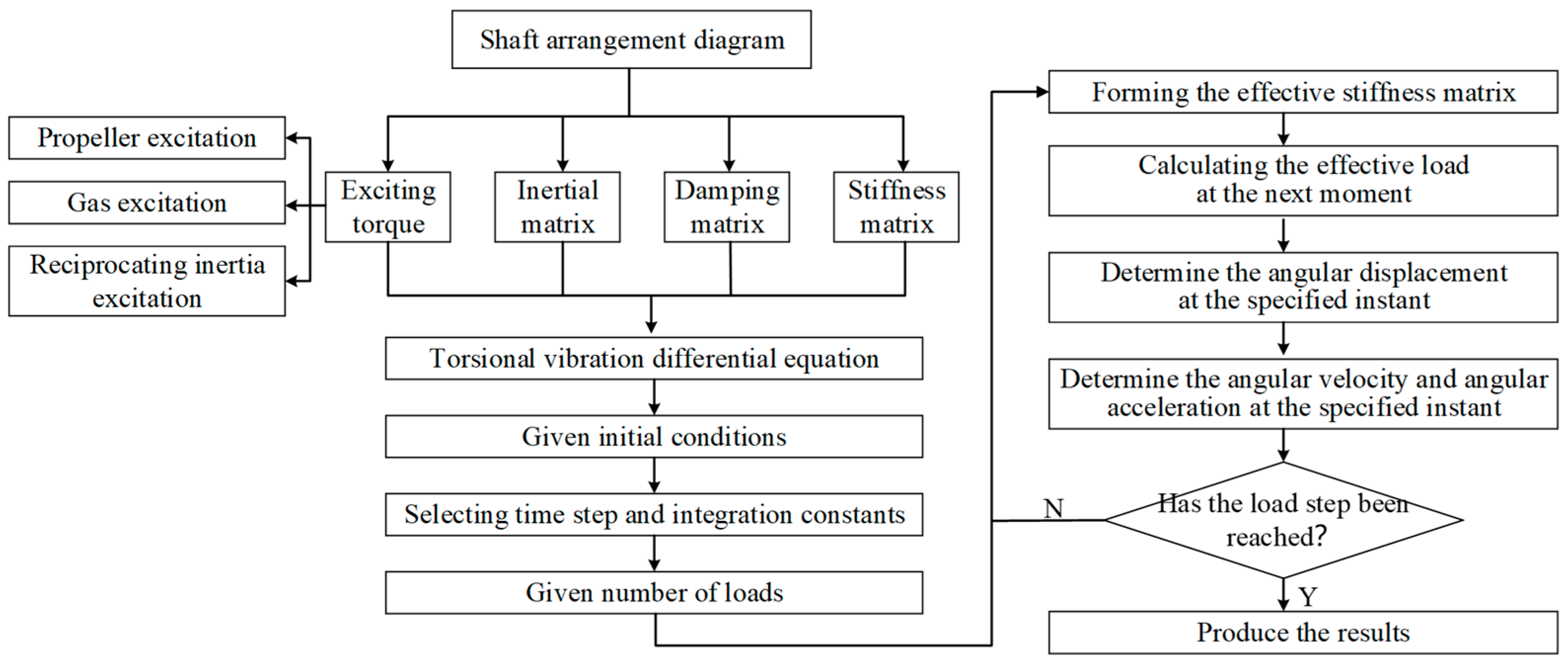
2.2. Research on Dynamic Response Methods

The transient vibration differential equations of the ship propulsion system are usually of multiple degrees of freedom, and the calculation is very extensive, making the solution very costly. To reduce calculation time and improve efficiency, numerical analysis methods are commonly used for calculation. This paper employs the Newmark-β method for step-by-step integration from a mathematical perspective, focusing on solving the system’s motion differential equations, solving the initial and boundary value problems of the motion differential equations, ensuring that they satisfy the motion differential equations at each moment, and representing the velocity and acceleration at a certain moment as a linear combination of displacements at adjacent moments. This allows the motion differential equations of the multi-degree-of-freedom vibration system to be transformed into an algebraic equation system represented by the displacement at discrete moments. There is no need to decouple the coupled motion differential equations; instead, they are numerically integrated step by step. Through this process, we can solve the dynamic response of the system at a series of discrete time points. The Newmark method assumes that under the known displacement θ , velocity θ ˙ , and acceleration θ ¨ at time t , the velocity and displacement at time t + t are represented as follows:
θ ˙ ( t + t ) = θ ˙ ( t ) + [ ( 1 γ ) θ ¨ ( t ) + γ θ ¨ ( t + t ) ] t
θ ( t + t ) = θ ( t ) + θ ˙ ( t ) t + 1 2 β θ ¨ ( t ) + β θ ¨ ( t + t ) t 2
where β and γ are two constants within the interval [0,1].
For Equation (3), it can be rewritten as:
θ ¨ ( t + t ) = 1 β t 2 ( θ ( t + t ) θ ( t ) ) 1 β t θ ˙ ( t ) ( 1 2 β 1 ) θ ¨ ( t )
Substituting (4) into (2) yields the following:
θ ¨ ( t + t ) = γ β t ( θ ( t + t ) θ ( t ) ) ( 1 γ β ) θ ˙ ( t ) + ( 1 γ 2 β ) θ ¨ ( t )
Considering the vibration differential equation at the time t + t yields the following:
J θ ¨ ( t + t ) + c θ ˙ ( t + t ) + K θ ( t + t ) = T ( t + t )
Substituting (4) and (5) into (6) yields the following:
J θ ¨ ( t + t ) + c θ ˙ ( t + t ) + K θ ( t + t ) = T ( t + t )
In the above formula, the following is calculated:
K ¯ = K + 1 β t 2 J + γ β t 2 c T ¯ = T ( t + t ) + J 1 β t 2 ( θ ( t ) ) 1 β t θ ˙ ( t ) ( 1 2 β 1 ) θ ¨ ( t ) + c γ β t ( θ ( t ) ) + ( γ β 1 ) θ ˙ ( t ) + ( 1 γ 2 β ) θ ¨ ( t )
where K ¯ represents the equivalent stiffness matrix, and T ¯ denotes the equivalent load vector. From Equation (7), the displacement vector θ ( t + t ) at time t + t can be obtained. Subsequently, the acceleration vector θ ¨ ( t + t ) and velocity vector θ ˙ ( t + t ) at a time t + t can be determined, respectively, from Equations (4) and (5).
Consequently, a procedure for analyzing the time domain transient response characteristics of the ship’s propulsion shaft system using the Newmark-β method can be established, as illustrated in Figure 1.

3. Transient Response Simulation

This paper takes the low-speed diesel engine propulsion shaft system of a 16000TEU container ship as an example, using the classic frequency domain equivalent system model, comprehensively considering the dynamic response simulation calculation method, and employing the Newmark-β method for time domain transient simulation calculations. It studies the relationship between the vibration torque and vibration stress of each component of the propulsion shaft system over time at a certain rotational speed and can intuitively observe the dynamic characteristics of the propulsion shaft system changing over time at a specific rotational speed. It analyzes the dynamic torque response amplitude of the shaft system and the stress of the shaft sections to determine whether they meet the navigation requirements. Since the maximum dynamic response of each shaft section is different under various operating conditions of the propulsion shaft system, to ensure the comprehensiveness of the calculation, it is necessary to obtain the maximum dynamic torque response of the propulsion shaft system under various operating conditions.

3.1. Main Calculation Parameters

The propulsion shaft system of a 16000TEU container ship operates at a low-speed diesel engine, which is composed of a propeller, an aft shaft bearing, a forward shaft bearing, two intermediate bearings, a shaft generator, a tail shaft, two intermediate shafts, a motor shaft, and a two-stroke low-speed diesel engine. The relevant parameters of the system equipment are shown in Table 1.

3.2. Simulation Modeling

In the study of the transient calculation model of the propulsion shaft system in Section 2.1, it has been understood that during the simplification process of the propulsion shaft system, components such as cylinders, flywheels, and propellers are treated as lumped mass points. According to the characteristics of the experimental ship’s propulsion shaft system, the rotor of the half-type structured shaft-driven generator is directly fitted onto the propulsion shaft system without bearing support, and it is also treated as a concentrated mass point for transient simulation calculation. The model diagram based on the classical frequency domain lumped-parameter method is depicted in Figure 2. The equivalent parameter model data used at this time are shown in Table 2.

3.3. Research on Incentive and Damping Parameters

3.3.1. Transient Excitation Calculation

In the dynamic response calculation of this ship’s propulsion shaft system, the excitation mainly considers the transient excitation of the diesel engine and the propeller excitation (which corresponds to “Q” in Equation (1)). The transient excitation of the diesel engine primarily consists of the gas excitation torque and the reciprocating inertia torque. Unlike the selection of the excitation torque of the diesel engine at each harmonic during steady-state torsional vibration calculations in the frequency domain, the excitation torque is calculated for each harmonic at every rotational speed across the full speed range. The calculation of the gas excitation torque for a two-stroke diesel engine is shown in Equation (9) [31].
T n = T n 0 + π 4 D 2 R v a v cos v ω t + b v sin v ω t = T n 0 + π 4 D 2 R v C v sin ( v ω t + Ψ v )
where T n is the average torque of a single cylinder, Nm; D is the diameter of the diesel engine cylinder, mm; R is the crank radius of the diesel engine, mm; a v is the sine component of the vth harmonic tangential force, N/mm2; b v is the cosine component of the vth harmonic tangential force, N/mm2; C v is the harmonic coefficient, N/mm2; Ψ v is the initial phase angle of the vth harmonic tangential force, rad; and ω t is the crankshaft angle, rad.
The amplitude of the excitation torque of a certain harmonic order produced by the gas pressure in the cylinder is shown in Equation (10) [31].
T v = π 4 D 2 R C V 10 3
The excitation torque produced by the reciprocating inertia force of a diesel engine cylinder is shown in Equation (11) [31].
T I = m R 2 ω 2 π 4 s i n 2 ( ω t δ ) 3 λ 4 + 9 λ 2 32 s i n 3 ( ω t δ ) λ 2 4 s i n 4 ( ω t δ ) + 5 λ 2 32 s i n 5 ( ω t δ ) 10 6
where T I is the reciprocating inertia force excitation torque, Nm; m is the total mass, kg; δ is the firing interval angle between any cylinder and the 1st cylinder, rad; λ is the ratio of the crank radius to the connecting rod length, λ = R / L ; and ω t is the crankshaft angle, rad.
The propeller excitation torque usually considers the single-blade passage excitation of the propeller, and its excitation torque is shown in Equation (12) [31].
M p = 9550 β N e n e ( n n e ) 2
where M p is the single-blade passage excitation of the propeller; N e is the rated power of the propeller; n e is the rated rotational speed of the propeller; n is the rotational speed of the propeller shaft; and β is the excitation factor, with an empirical value of β = 0.0075 .
Utilizing Equations (9)–(12), the excitations due to gas, reciprocating inertia, and the propeller can be individually determined. The combined effect of gas and reciprocating inertia excitations constitutes the diesel engine excitation. Varied firing sequences lead to distinct firing angles, thereby introducing phase differences among these excitations. During numerical computation, these excitations are applied to the simplified mass points of each diesel engine cylinder, taking into account their respective phase angles. Furthermore, the text assumes that the propeller excitation has an initial phase angle of zero relative to the first cylinder of the diesel engine. The propeller excitation predominantly accounts for the excitation at the blade passing frequency and its multiples, which are imposed on the simplified mass points of the propeller model.

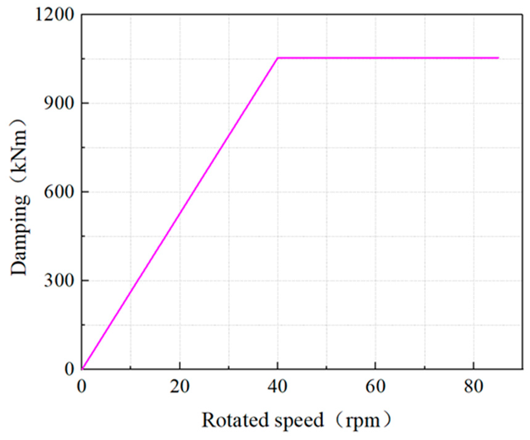
3.3.2. Transient Damping Calculation

In the computation of dynamic responses within a shaft system, damping is commonly divided into categories of relative damping and absolute damping, which correspond to internal and external damping in the frequency domain. During steady-state torsional vibration analysis within the frequency domain, calculations are performed for each harmonic excitation, excluding the DC component, by directly incorporating the absolute damping values into the damping matrix. However, in the transient analysis conducted in the time domain, the impact of external factors such as ice loads, sea waves, and explosions is considered. This may result in fluctuations in the rotational speed of the propulsion shaft system, rendering the direct substitution of absolute damping values into the damping matrix inappropriate. The absolute damping torque, resulting from the discrepancy between instantaneous and average rotational speeds, is applied as an external excitation torque to the respective mass nodes. To accurately determine the absolute damping torque at a specific rotational speed, it is necessary to deduct the average rotational speed of the concentrated mass node from the calculation. The damping torque is calculated as the product of the absolute damping and the difference in torsional velocity, as depicted in Equation (13) [32].
T t ( t ) = C a b s × f ˙ ( t ) f ˙ a v e ( t )
where C a b s is the absolute damping, Nms/rad; ϕ ˙ ( t ) is the instantaneous rotational speed, rad/s; and ϕ ˙ a v e ( t ) is the average rotational speed, rad/s. Relative damping serves to compensate for the change in the twist angle between the two concentrated mass points, determined by the damping coefficient and stiffness. Relative damping does not need to calculate the average velocity and can be directly embedded in the time domain calculation damping matrix.
In the discrete mass model, the predominant form of damping for the propeller is absolute damping, which can be categorized into two distinct forms: one form is the torque absorbed by the propeller from the main engine, namely the propeller torque in the hydrodynamic performance of the propeller; the other form occurs when the propeller, during operation, does not absorb the torque from the main engine, leading to the generation of vibrations in the propeller. In this paper, the Prodam damping model is employed, which assumes a constant damping value when the rotational speed exceeds half of the maximum continuous rating (MCR) speed. Below half the MCR speed, the damping increases linearly, as depicted in Figure 3.

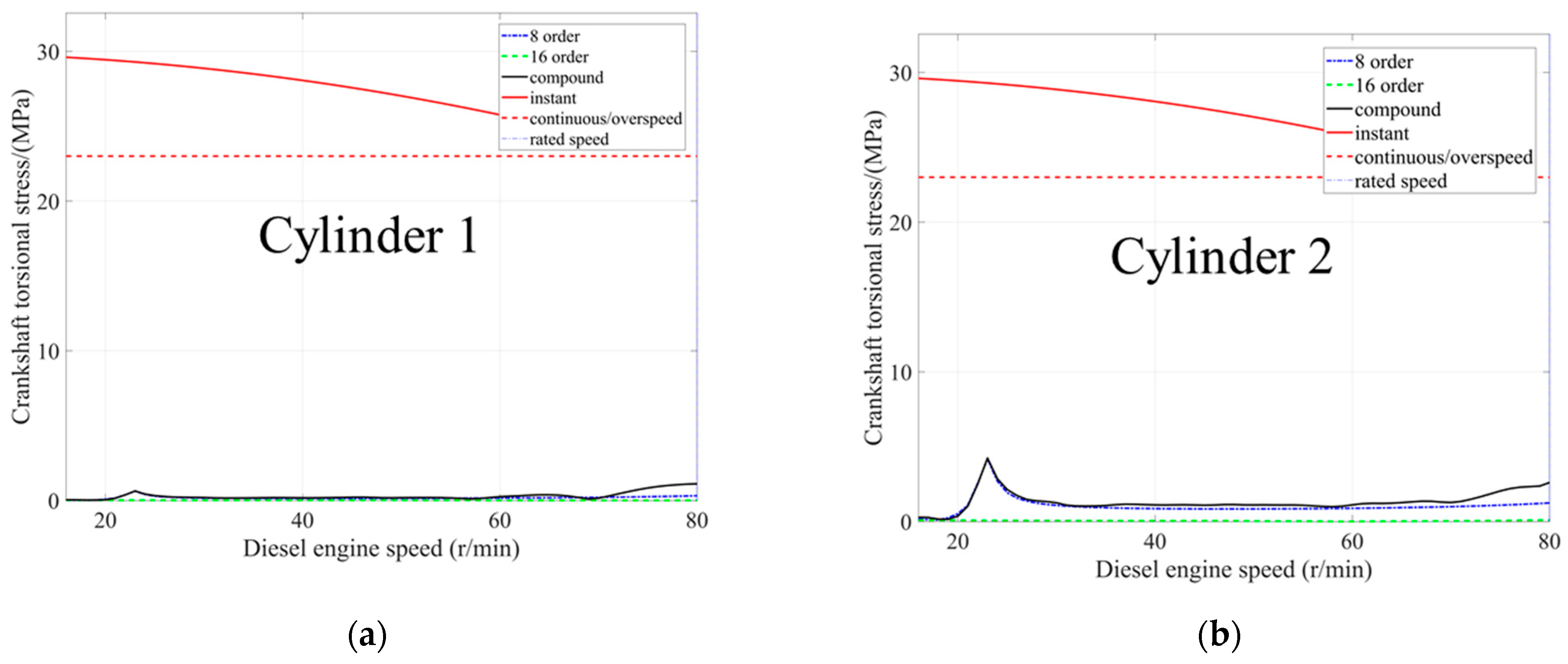
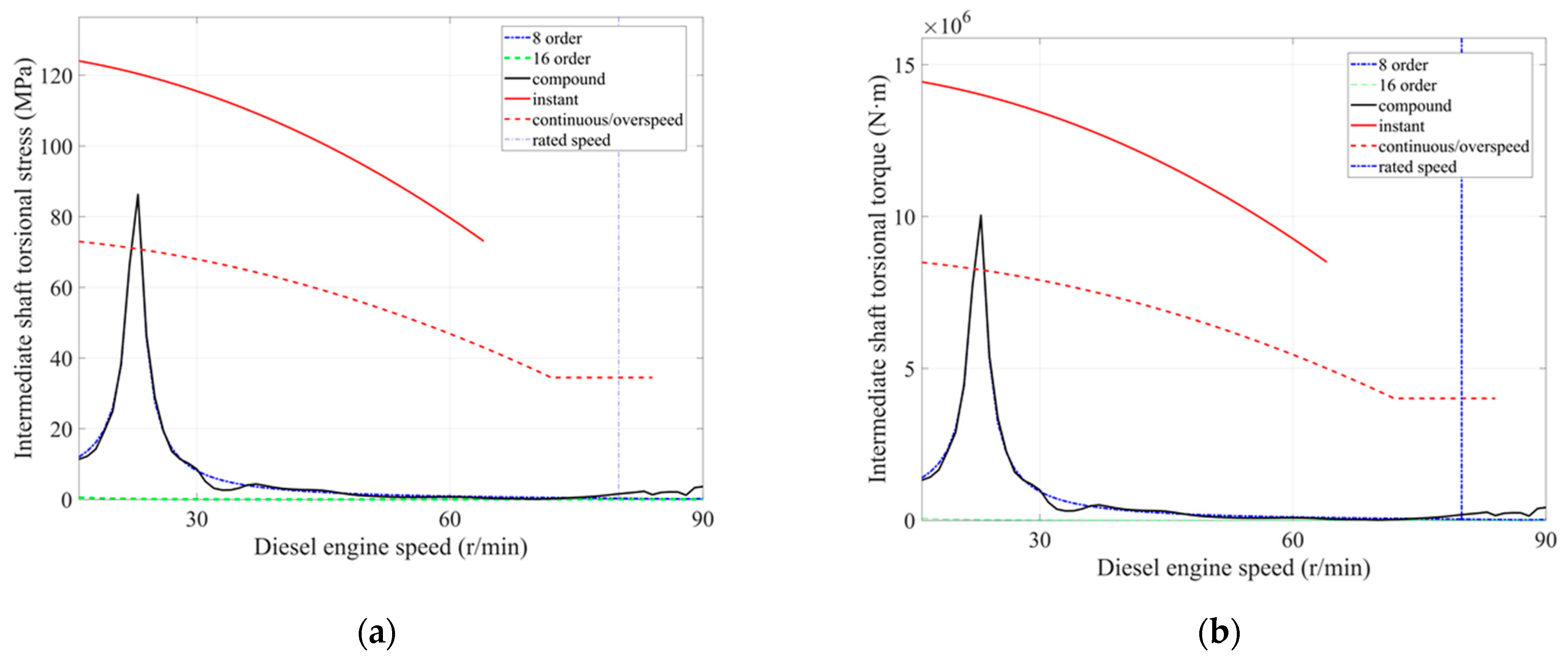
3.4. Simulation Result Analysis

The classic lumped-parameter equivalent system model and the Newmark-β method for step-by-step integration were utilized to conduct a time domain transient simulation of the propulsion shaft system, which includes a shaft-driven generator. The external excitation loads are defined by Equations (9)–(12). From Equation (1), the synthesized amplitude vector for each harmonic of the propulsion shaft system can be obtained. The product of this amplitude vector with the stiffness matrix yields the desired vibration torque. The vibration stress can be calculated using Equation (14).
F t = T t π 16 D 3 1 d D 4
where T t represents the vibration torque, kNm; D represents the outer diameter of the shaft system, mm; and d represents the inner diameter of the shaft system, mm.
Through the calculation of vibration torque and vibration stress under full-speed operating conditions for different unit equipment, the torsional vibration stress curves at each cylinder were obtained, as shown in Figure 4. It can be observed from Figure 4 that the torsional vibration stress at the 8th harmonic cylinder reaches its maximum, and there is a distinct resonance speed point at a propeller shaft system rotational speed of 23.0 r/min. The calculated vibration stresses for the first five cylinders are all below the allowable continuous stress; the vibration stress at the sixth cylinder approaches the allowable continuous stress, but the vibration stresses at the seventh and eighth cylinders exceed the allowable continuous stress without surpassing the allowable instantaneous stress curve. Therefore, during actual navigation, when the rotational speed is near 23 r/min, a strict speed limit should be set, and the response characteristics of the shaft system and the state of cylinders seven and eight should be closely monitored. The propulsion shaft system of this type of low-speed diesel engine is significantly affected by the 8th and 16th harmonic excitation torques.
The article employs the system matrix method for numerical analysis, and the simulation calculation results for the torsional vibration stress and vibration torque at the intermediate shaft under normal firing conditions, as shown in Figure 5. Analysis of the curves reveals that the maximum torsional vibration stress occurs at the 8th harmonic of the intermediate shaft, with a resonance point present. It is noteworthy that the vibration stress near the resonance point and its vicinity has exceeded the allowable continuous stress but has not surpassed the allowable instantaneous stress curve; the vibration torque reached 107 Nm, which exceeds the allowable continuous torque. Thus, in actual navigation, it is recommended to strictly limit the rotational speed range to near 23 r/min and to closely monitor the response characteristics of the shaft system near this speed to avoid adverse effects caused by resonance and to ensure the safe and reliable operation of the system.
Using the system matrix method for numerical analysis and through MATLAB R2022b programming under normal firing conditions, the vibration stress and vibration torque curves of the propeller shaft were obtained, as shown in Figure 6. Analysis of Figure 6 indicates that at the 8th harmonic of the propeller shaft, the torsional vibration stress reaches its maximum value, up to 65 MPa, which is far beyond the allowable continuous stress. At this point, the vibration torque reaches 107 Nm, which is far beyond the allowable continuous stress but does not exceed the allowable instantaneous stress curve.
From Figure 4, Figure 5 and Figure 6, the vibration stress curves and vibration torque curves of key unit equipment indicate that there are resonance points in the propulsion shaft system, and some equipment exceeds the allowable continuous stress and allowable continuous torque. During actual navigation, a speed limit should be set, and it is advisable to quickly pass through the 20–30 r/min speed range to avoid fatigue damage to the equipment.

4. Real Ship Experimental Verification

4.1. Experimental Equipment

In the dynamic response experiment of the low-speed diesel engine propulsion shaft system, the resistance strain measurement method was used. Resistance strain gauges were attached to the determined measurement points and connected to the DH5905N wireless node modules. The sensor nodes were connected to a laptop via a router, which was set up and controlled by the DHDAS dynamic signal acquisition and analysis system to collect the actual strain curves under different operating conditions of the propulsion shaft system. The schematic diagram and physical image of the experimental system are shown in Figure 7.
The strain gauges used are manufactured by Aviation Electric Measurement Co., Ltd, located in Xi’an, China. and are secured to the polished shaft surface with special adhesive before testing and protected with silicone. The specification of the single coil resistance is 350 Ω, and the sensitivity factor is 2.09. Since the strain gauges are fixed on the propulsion shafting system, when the shafting system undergoes torsional vibration, the sensitive grid of the strain gauge will deform by an equivalent amount, thereby causing changes in the resistance value of the sensitive grid. This change in resistance represents the torsional deformation of the propulsion shafting system. In strain measurement, the measurement circuit is composed of resistance strain gauges arranged in a certain order to form a circuit with certain characteristics for experimental measurement. The resistance change of the bridge strain gauges during the measurement process is output in the form of voltage or current. Before starting the measurement, it is necessary to zero the offset to eliminate any initial imbalance or error. Each set of strain gauges is connected to the differential analog channel input of the DH5905N wireless data transmitter manufactured by Donghua Testing Co., Ltd., located in Taizhou City, China. The bridge voltage of DH5905N is set to 3 V, with an indication error not exceeding 5%, and the zero drift is less than 3 με/2 h [33]. Due to the split design of the equipment, the power module and the acquisition module are symmetrically installed on the propulsion shafting system, which does not affect the balance of the shafting system during measurement; there is no wire connection between the upper computer and the acquisition module, and WiFi wireless transmission is used to facilitate the acquisition of torsional vibration data from the propulsion shafting system.

4.2. Experimental System Layout and Parameter Setting

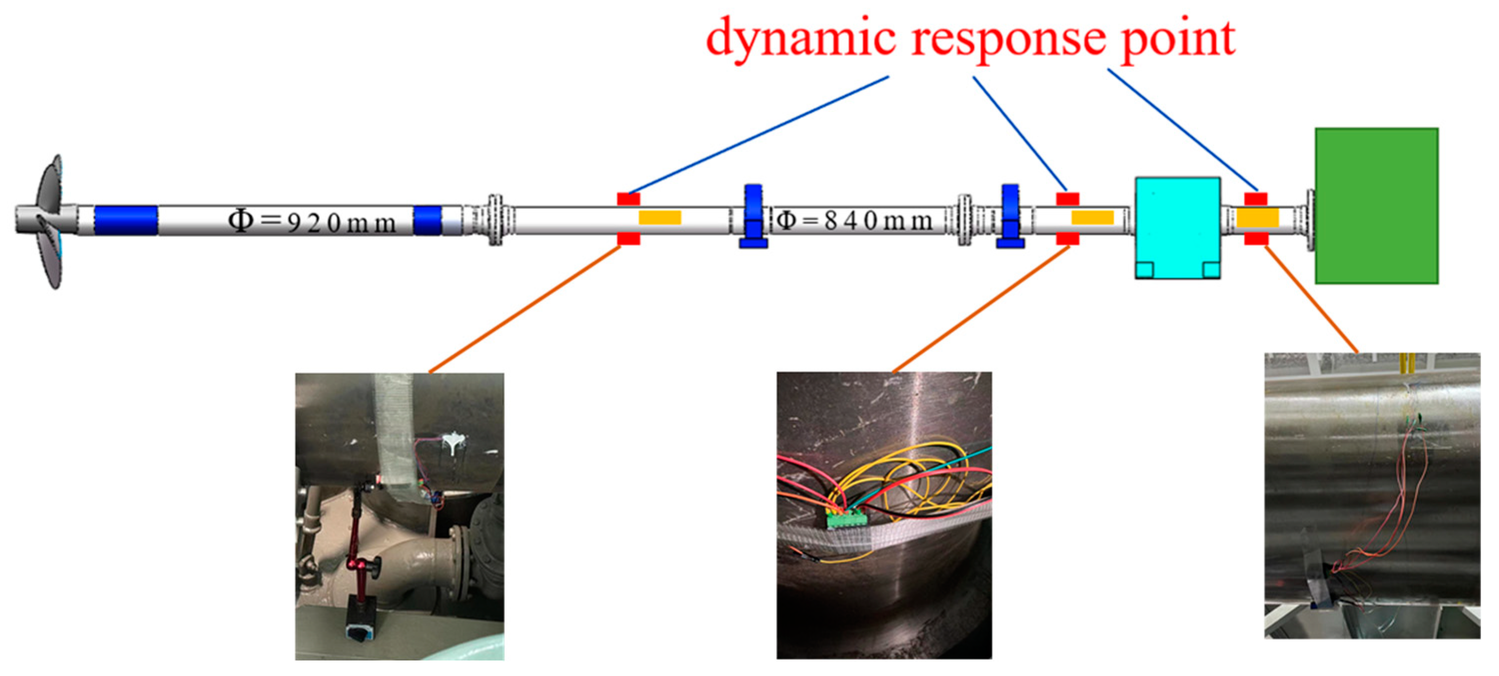
4.2.1. Experimental Point Layout

The experiment in this study took the propulsion shaft system of a 16000TEU container ship’s low-speed diesel engine as the experimental subject and conducted sea trials in the East China Sea, where the sea conditions were between two and three levels, with the overall wind and wave direction from the northwest. To verify the dynamic impact of the shaft-driven generator without a support bearing on the propulsion shaft system, three measurement points were arranged in this experiment. They were located at the midpoint of the rear intermediate shaft, the midpoint behind the motor on the motor shaft, and the midpoint in front of the motor on the motor shaft, respectively, to measure their vibration torque and vibration stress, allowing for a comparative analysis of the data from the three measurement points. The schematic diagram of the measuring point position and the actual measuring point arrangement are shown in Figure 8.

4.2.2. Experimental Measurement

Before initiating the test, the relevant parameters for the strain gauges and experimental equipment should be pre-set in the DHDAS Dynamic Signal Acquisition and Analysis System, as shown in Table 3, detailing the parameter settings for all measurement points and ensuring that each instrument is wirelessly connected to the laptop. During the ship’s navigation experiment and data collection process, the ship’s diesel engine continuously outputs at the rated power without the load of the shaft generator connected. The experimental collection revolves primarily around speeds near the rated speed, mainly because in actual ship navigation, the main engine mainly operates at the rated speed and power condition. Here, the focus is on analyzing the speed points near the rated speed. The DHDAS Dynamic Signal Acquisition and Analysis System records in detail the torque amplitude and stress curves at test speeds of 73 rpm, 75 rpm, 77 rpm, 79 rpm, and 80 rpm. When the shaft generator is connected to the load, the load is 3207 kW, and the propulsion shafting system’s speed is based on the actual sea conditions. The DHDAS Dynamic Signal Acquisition and Analysis System records in detail the torque amplitude and stress curves at the test speed of 53 rpm.

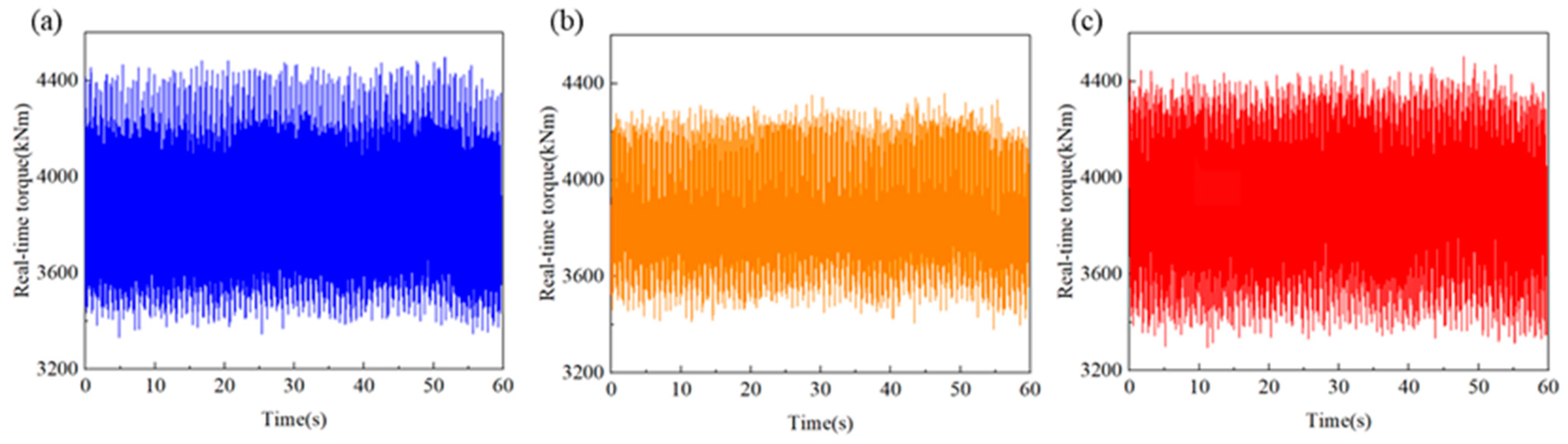
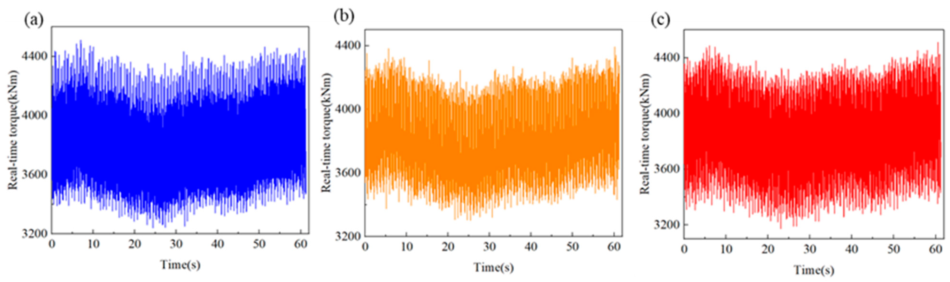
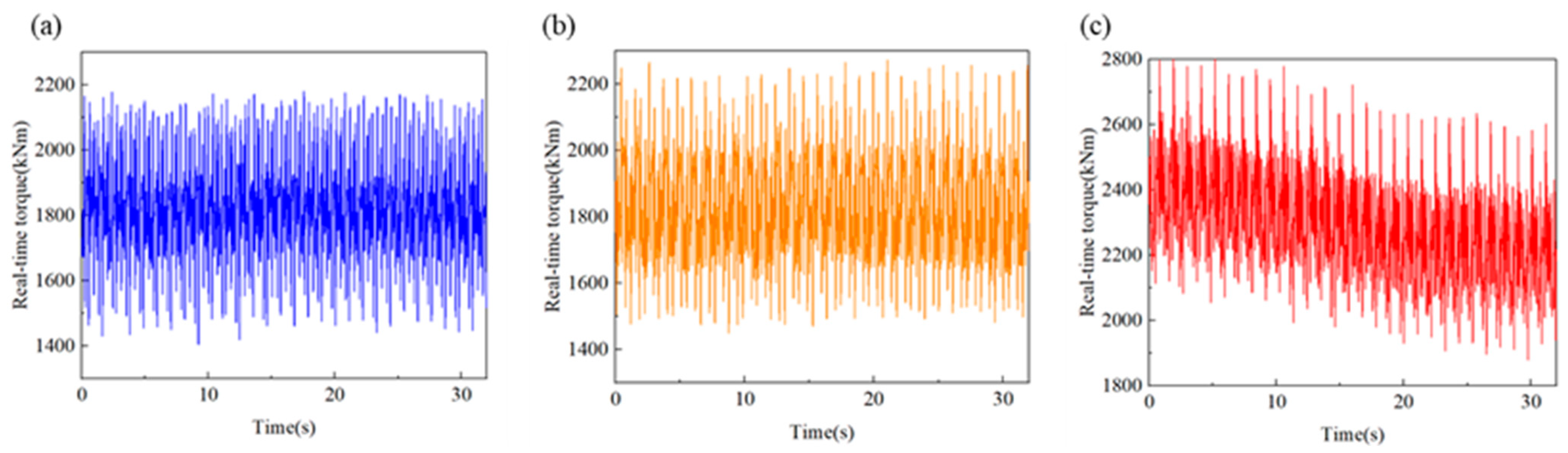
4.3. Experimental Result Analysis

The data collected during the sea trial experimental of the 16 k container ship in the East China Sea ensured that the sea area, wind, waves, temperature, and humidity were completely in line with standard operating conditions, making them authentic and effective. In the experiment, when the shaft-driven generator load was not connected, the navigation state was maintained in a straight line, and the main engine operated stably at the rated power of 45,000 kW, respectively, collecting the vibration torque at the propulsion shaft system rotational speeds of 73 r/min, 75 r/min, 77 r/min, 79 r/min, and 80 r/min. The torque amplitudes [34] measured at the midpoint of the intermediate shaft and the front and rear ends of the motor are shown in Figure 9, Figure 10, Figure 11, Figure 12 and Figure 13 for this time period.
During the experiment, when the shaft-driven generator load was connected, the navigation state was maintained in a straight line, and the main engine operated at a power of 13,235 kW, with the propulsion shaft system rotational speed at 53 r/min and the shaft-driven generator connected to a load of 3207 kW. At this time, the torque amplitudes measured at the midpoint of the intermediate shaft and the front and rear ends of the motor are shown in Figure 14.

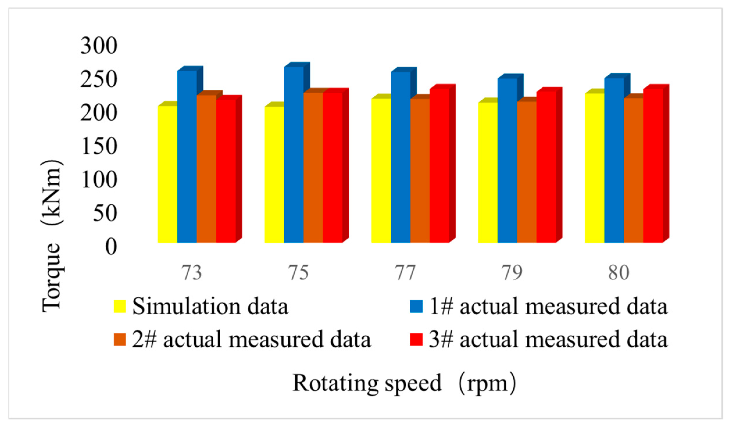
4.4. Simulation and Experimental Result Comparison Analysis

In this paper, a detailed comparison and analysis of the simulation and experimental results were conducted. When the shaft-driven generator in the ship’s propulsion shaft system was not connected to the load, the transient torque simulation calculation results and experimental results for the rear intermediate shaft are shown in Figure 15. Since only the dynamic torque at the following rotational speed points was collected in the actual ship experiment, the peak torque corresponding to the rotational speed points in the full-speed simulation calculation was selected to evaluate the consistency and differences between the two. Through the comparative analysis in Figure 15, it can be seen that the vibration torque obtained by the simulation calculation using the classic lumped-parameter equivalent system model and the Newmark-β step-by-step integration method has a small error with the actual measured torque in front of and behind the motor, all less than 10%, but the error with the rear intermediate shaft measurement point is relatively large, up to nearly 20%. The source of this discrepancy may lie in the fact that the current simulations of the dynamic response of the propulsion shafting system have neglected the influence of the propeller’s pulsating dynamic forces on the system’s torsional vibrations. There is a minor discrepancy between the results of the dynamic response simulations and the measured torque data both upstream and downstream of the electric motor. However, both deviate considerably from the measured torque at the mid-shaft measurement point. This divergence is predominantly attributed to the mid-shaft measurement point’s proximity to the propeller, which subjects it to a greater impact from the propeller’s pulsating forces. Conversely, the measurement points located further away from the propeller, both upstream and downstream of the motor, exhibit measured data that are less affected by these pulsating forces.
The transient torque simulation calculation results and experimental results for the propeller shaft when the shaft-driven generator in the ship’s propulsion shaft system was connected to the load are shown in Table 4. Table 4 shows the simulated vibration torque of the propulsion shaft system and the actual measured torque at the midpoint of the intermediate shaft and the front and rear ends of the motor at a rotational speed of 53 r/min. The comparative analysis shows that the simulation torque results are less than 6% different from the actual measured torque results at different measurement points. Therefore, in actual ship navigation, the impact of the unsupported shaft-driven generator on the propulsion shaft system is small, which has a certain guiding significance for the later installation and design of the shaft-driven generator.

5. Conclusions

This paper employs the classic lumped-parameter equivalent system model and the Newmark-β step-by-step integration method to conduct dynamic response simulation calculations and experimental verification on the 16000TEU container ship’s low-speed diesel engine propulsion shaft system with a shaft-driven generator. The vibration torque amplitude on the propulsion shaft system was obtained. Through the comparison and analysis of the simulation and experimental results, the following conclusions were drawn:
(a)
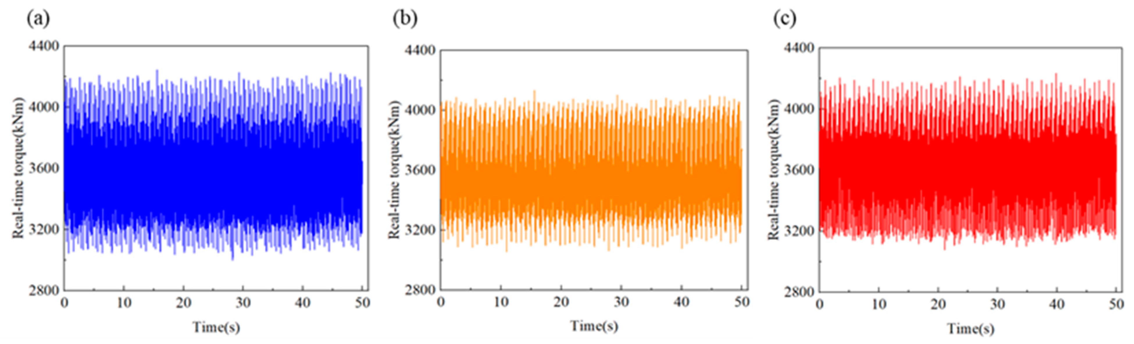
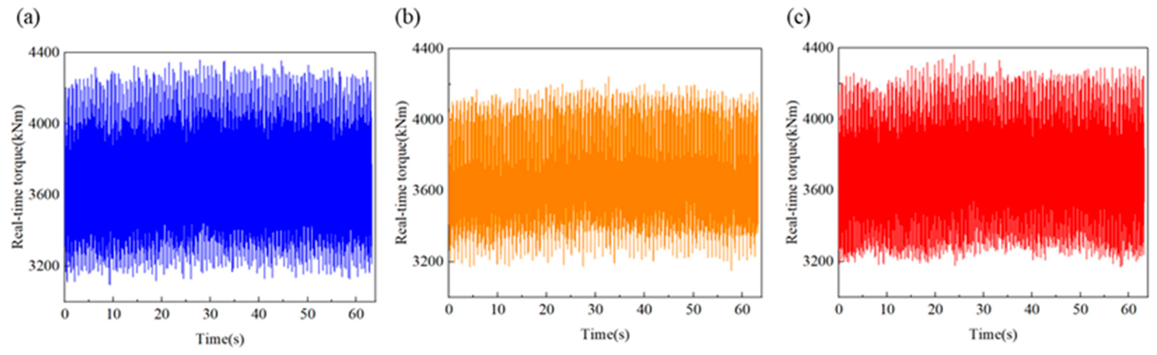
After the installation of the shaft-driven generator with or without bearing support, the measured torque at the pre- and post-generator measurement points in the propulsion shaft system is less than 10% different from the results of dynamic response simulation calculations, confirming the consistency between simulation results and actual ship experimental results. This further verifies the accuracy of the lumped-parameter system theoretical model of the propulsion shaft system with the shaft-driven generator.
(b)
Based on the actual ship experimental data, the theoretical calculation model is further calibrated, and the empirical coefficients in the calculation formula for the diesel engine excitation are revised to improve the accuracy of the simulation calculations.
(c)
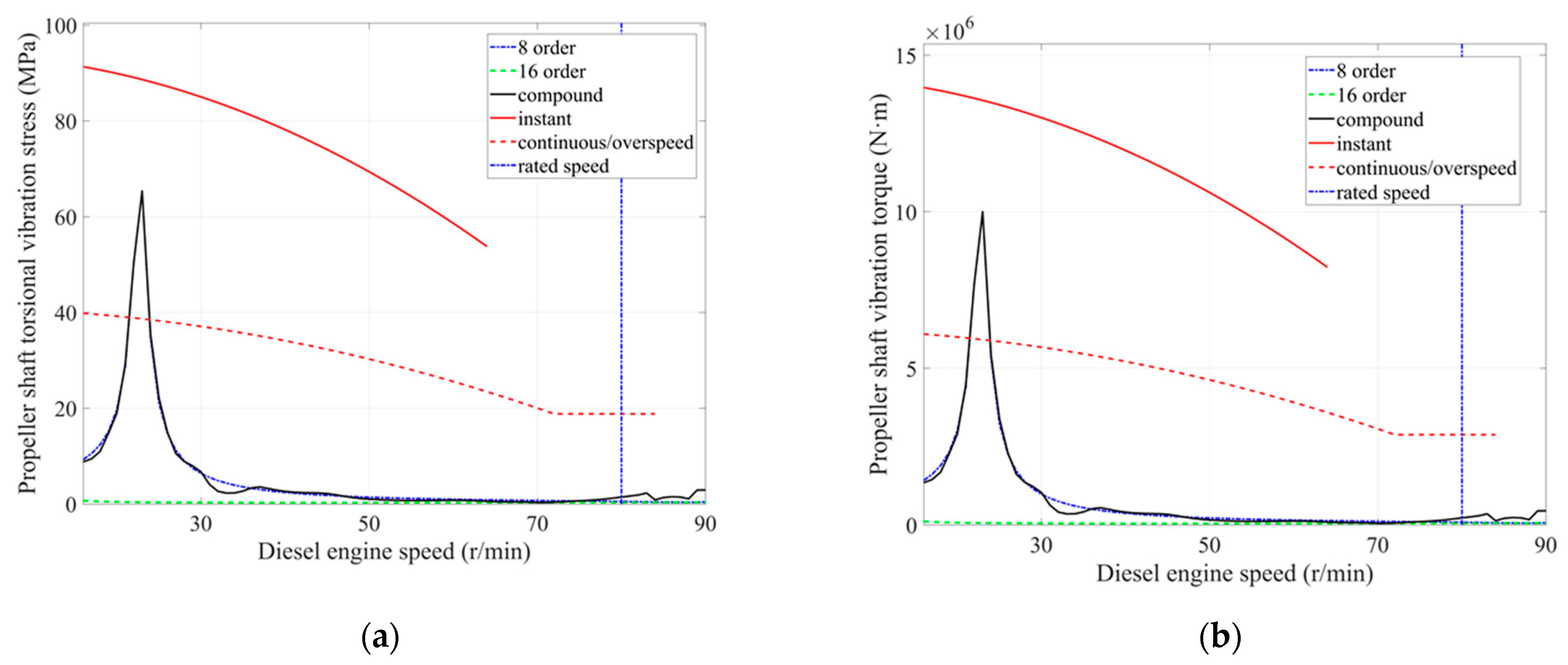
Under normal operating conditions, the measured torque results at different measurement points are far less than the continuous allowable torque of 4.01 × 10⁶ N·m and the instantaneous torque. This confirms that the installation of the shaft-driven generator without bearing support has a minimal impact on the dynamic response of the propulsion shaft system. The dynamic torque amplitude is within the allowable range, further indicating that the propulsion shaft system with the shaft-driven generator without bearing support can safely operate within the working speed range. This provides theoretical and experimental support for the future installation of the propulsion shaft system with the shaft-driven generator without bearing support.

Author Contributions

Conceptualization, methodology, investigation, writing—original draft, and writing—review and editing, Y.G.; conceptualization, methodology, formal analysis, investigation, and writing—original draft, Z.M.; resources, supervision, funding acquisition, and validation, R.Z.; conceptualization, methodology, formal analysis, J.W.; formal analysis, validation, L.D. All authors have read and agreed to the published version of the manuscript.

Funding

This research was funded by the High-Tech Research and Development Program: development of high-ice-class propulsion and manipulation systems for polar regions (project number: K24532-1-2); the funder is Zhou Ruiping.

Institutional Review Board Statement

Not applicable.

Informed Consent Statement

Not applicable.

Data Availability Statement

The data that support the findings of this study are available from the corresponding author upon reasonable request.

Conflicts of Interest

Author Jianzheng Wang was employed by the company Shanghai Marine Diesel Engine Research Institute. The remaining authors declare that the research was conducted in the absence of any commercial or financial relationships that could be construed as a potential conflict of interest.

References

  1. Lee, D.; Yu, J. Transient and Unstable Torsional Vibrations on a 4-Stroke Marine Diesel Engine. In Proceedings of the Internal Combustion Engine Division Spring Technical Conference, Salzburg, Austria, 11–14 May 2003. [Google Scholar]
  2. Manngård, M.; Koene, I.; Lund, W.; Haikonen, S.; Fagerholm, F.; Wilczek, M.; Toivonen, H. Torque estimation in marine propulsion systems. Mech. Syst. Signal Proc. 2022, 172, 108969. [Google Scholar] [CrossRef]
  3. Liao, P. Research and Software Development on Transient Torsional Vibration of Typical Propulsion Shaft Systems of Ships in Ice Areas. Master’s Thesis, Wuhan University of Technology, Wuhan, China, 2018. [Google Scholar]
  4. Li, J. Analysis and Research on Torsional Vibration of Propulsion Shafting of Ships Sailing in Ice Areas. Master’s Thesis, Wuhan University of Technology, Wuhan, China, 2016. [Google Scholar]
  5. Firouzi, J.; Ghassemi, H.; Shadmani, M. Analytical model for coupled torsional-longitudinal vibrations of marine propeller shafting system considering blade characteristics. Appl. Math. Model. 2021, 94, 737–756. [Google Scholar] [CrossRef]
  6. Xu, X.; Zhou, R.; Wang, M. Research on the Marine Shafting Torsional Vibration with Gears Transmission. Int. J. Eng. Ind. 2012, 3, 99–111. [Google Scholar]
  7. Polić, D.; Ehlers, S.; Æsøy, V. Propeller torque load and propeller shaft torque response correlation during ice-propeller interaction. J. Mar. Sci. Appl. 2017, 16, 1–9. [Google Scholar] [CrossRef]
  8. Polić, D.; Æsøy, V.; Ehlers, S. Transient simulation of the propulsion machinery system operating in ice–modeling approach. Ocean Eng. 2016, 124, 437–449. [Google Scholar] [CrossRef]
  9. Zhao, F. Research on Random Excitation Response of Ship Propulsion Shafting Based on Non-Parametric Modeling. Master’s Thesis, Dalian Maritime University, Dalian, China, 2023. [Google Scholar]
  10. Zambon, A.; Moro, L. Torsional vibration analysis of diesel driven propulsion systems: The case of a polar-class vessel. Ocean Eng. 2022, 245, 110330. [Google Scholar] [CrossRef]
  11. Zambon, A.; Moro, L.; Oldford, D. Impact of different characteristics of the ice–propeller interaction torque on the torsional vibration response of a Polar-Class shaftline. Ocean Eng. 2022, 266, 112630. [Google Scholar] [CrossRef]
  12. Zambon, A.; Moro, L.; Kennedy, A.; Oldford, D. Torsional vibrations of Polar-Class shaftlines: Correlating ice–propeller interaction torque to sea ice thickness. Ocean Eng. 2023, 267, 113250. [Google Scholar] [CrossRef]
  13. Shen, X. Research on Torsional Vibration Characteristics of High-Power Complex Propulsion Shafting. Master’s Thesis, Shanghai Jiao Tong University, Shanghai, China, 2013. [Google Scholar]
  14. Yang, Y.; Tang, W.; Ma, J. Optimal design for a VLCC propulsion system based on torsional vibration analysis. Procedia Eng. 2011, 15, 5378–5383. [Google Scholar] [CrossRef]
  15. Huang, G. Research on Simulation Method and Application of Shaft Torsional Vibration. Master’s Thesis, Wuhan University of Technology, Wuhan, China, 2016. [Google Scholar]
  16. Senjanović, I.; Ančić, I.; Magazinović, G.; Alujević, N.; Vladimir, N.; Cho, D. Validation of analytical methods for the estimation of the torsional vibrations of ship power transmission systems. Ocean Eng. 2019, 184, 107–120. [Google Scholar] [CrossRef]
  17. Senjanović, I.; Hadžić, N.; Murawski, L.; Vladimir, N.; Alujević, N.; Cho, D. Analytical procedures for torsional vibration analysis of ship power transmission system. Eng. Struct. 2019, 178, 227–244. [Google Scholar] [CrossRef]
  18. Batrak, Y.; Serdjuchenko, A.; Tarasenko, A. Calculation of Torsional Vibration Responses in Propulsion Shafting System Caused by Ice Impacts. In Proceedings of the Torsional Vibration Symposium, Salzburg, Austria, 21–23 May 2014. [Google Scholar]
  19. Batrak, Y.; Serdjuchenko, A.; Tarasenko, A. Calculation of propulsion shafting transient torsional vibration induced by ice Impacts on the Propeller Blades. In Proceedings of the WMTC, Saint-Petersburg, Russia, 29 May–1 June 2012. [Google Scholar]
  20. Batrak, Y. Ice induced propulsion shafting torsional vibration analysis issues and case studies. In Proceedings of the Torsional Vibration Symposium, Salzburg, Austria, 8–9 June 2017. [Google Scholar]
  21. Hu, Y. Design and Development of Three-Dimensional Analysis Platform for Ship Shafting. Master’s Thesis, Wuhan University of Technology, Wuhan, China, 2019. [Google Scholar]
  22. Vlahopoulos, N.; Zhao, X. An investigation of power flow in the mid-frequency range for systems of co-linear beams based on a hybrid finite element formulation. J. Sound Vibr. 2001, 242, 445–473. [Google Scholar] [CrossRef]
  23. Bulut, G. Dynamic stability analysis of torsional vibrations of a shaft system connected by a Hooke’s joint through a continuous system model. J. Sound Vibr. 2014, 333, 3691–3701. [Google Scholar] [CrossRef]
  24. Turhan, Ö.; Bulut, G. Linearly coupled shaft torsional and blade-bending vibrations in multi-stage rotor-blade systems. J. Sound Vibr. 2006, 296, 292–318. [Google Scholar] [CrossRef]
  25. Murawski, L.; Charchalis, A. Simplified method of torsional vibration calculation of marine power transmission system. Mar. Struct. 2014, 39, 335–349. [Google Scholar] [CrossRef]
  26. Murawski, L. Shaft line alignment analysis taking ship construction flexibility and deformations into consideration. Mar. Struct. 2015, 18, 62–84. [Google Scholar] [CrossRef]
  27. Buchacz, A. Introduction to synthesis of the torsional vibrating discrete-continuous mechatronic systems by means of the hypergraphs and structural numbers method. J. Vibroeng. 2012, 14, 514–519. [Google Scholar]
  28. Han, H.; Lee, K. Experimental verification for lateral-torsional coupled vibration of the propulsion shaft system in a ship. Eng. Fract. Mech. 2019, 104, 758–771. [Google Scholar] [CrossRef]
  29. Han, H.; Lee, K.; Park, S. Parametric study to identify the cause of high torsional vibration of the propulsion shaft in the ship. Eng. Fail. Anal. 2016, 59, 334–346. [Google Scholar] [CrossRef]
  30. Han, H.; Lee, K.; Park, S. Estimate of the fatigue life of the propulsion shaft from torsional vibration measurement and the linear damage summation law in ships. Ocean Eng. 2015, 107, 212–221. [Google Scholar] [CrossRef]
  31. Wang, Q.; Ying, Q.; Yang, S. Internal Combustion Engine Shafting Torsional Vibration, 1st ed.; Dalian University of Technology Press: Dalian, China, 1991; pp. 75–102. [Google Scholar]
  32. ICAS. International Association of Classification Societies: Polar Class Draft Technical Background Note for Shafting [S]; IACS: Kolkata, India, 2016. [Google Scholar]
  33. Siddique, M.F.; Ahmad, Z.; Ullah, N.; Kim, J. A Hybrid Deep Learning Approach: Integrating Short-Time Fourier Transform and Continuous Wavelet Transform for Improved Pipeline Leak Detection. Sensors 2023, 23, 8079. [Google Scholar] [CrossRef] [PubMed]
  34. Siddique, M.F.; Ahmad, Z.; Ullah, N.; Kim, J. Pipeline leak diagnosis based on leak-augmented scalograms and deep learning. Eng. Appl. Comp. Fluid. 2023, 17, 2225577. [Google Scholar] [CrossRef]
Figure 1. Flowchart for solving the time domain dynamic response Using the Newmark-β method.
Applsci 14 06769 g001
Figure 2. Lumped-parameter model diagram.
Applsci 14 06769 g002
Figure 3. Propeller damping curve diagram (Prodam damping model).
Applsci 14 06769 g003
Figure 4. Torsional vibration stress curves of the crankshaft (normal firing): (a) cylinder 1 torsional stress; (b) cylinder 2 torsional stress; (c) cylinder 3 torsional stress; (d) cylinder 4 torsional stress; (e) cylinder 5 torsional stress; (f) cylinder 6 torsional stress; (g) cylinder 7 torsional stress; and (h) cylinder 8 torsional stress.
Applsci 14 06769 g004aApplsci 14 06769 g004b
Figure 5. Vibration stress and torque curves at intermediate shaft: (a) vibration stress; and (b) vibration torque.
Applsci 14 06769 g005
Figure 6. Vibration stress and torque curves at propeller shaft: (a) vibration stress; and (b) vibration torque.
Applsci 14 06769 g006
Figure 7. Experimental system diagram: (a) schematic diagram of the experimental system; and (b) physical image of the experimental system.
Applsci 14 06769 g007
Figure 8. Measuring point position diagram and actual measuring point layout diagram.
Applsci 14 06769 g008
Figure 9. Torque amplitude at different measurement points at 73 r/min: (a) torque amplitude at the midpoint of the intermediate shaft; (b) torque amplitude at the rear end of the motor; and (c) torque amplitude at the front end of the motor.
Applsci 14 06769 g009
Figure 10. Torque amplitude at different measurement points at 75 r/min: (a) torque amplitude at the midpoint of the intermediate shaft; (b) torque amplitude at the rear end of the motor; and (c) torque amplitude at the front end of the motor.
Applsci 14 06769 g010
Figure 11. Torque amplitude at different measurement points at 77 r/min: (a) torque amplitude at the midpoint of the intermediate shaft; (b) torque amplitude at the rear end of the motor; and (c) torque amplitude at the front end of the motor.
Applsci 14 06769 g011
Figure 12. Torque amplitude at different measurement points at 79 r/min: (a) torque amplitude at the midpoint of the intermediate shaft; (b) torque amplitude at the rear end of the motor; and (c) torque amplitude at the front end of the motor.
Applsci 14 06769 g012
Figure 13. Torque amplitude at different measurement points at 80 r/min: (a) torque amplitude at the midpoint of the intermediate shaft; (b) torque amplitude at the rear end of the motor; and (c) torque amplitude at the front end of the motor.
Applsci 14 06769 g013
Figure 14. Torque amplitude at different measurement points at 53 r/min: (a) torque amplitude at the midpoint of the intermediate shaft; (b) torque amplitude at the rear end of the motor; and (c) torque amplitude at the front end of the motor.
Applsci 14 06769 g014
Figure 15. Comparison of simulation and experimental results.
Applsci 14 06769 g015
Table 1. Relevant parameters of the propulsion shaft system.
EquipmentParameterEquipmentParameter
main enginemodel8G95ME-Cpropellermoment of inertia498,093 kgm2
maximum continuous output power45,300 kWmass80,105 kg
maximum continuous speed80 r/minnumber of blades5
number of cylinders8diameter10.1 m
cylinder bore diameter950 mmvibration dampermodelGeislinger D260/GU
firing order1-8-3-4-7-2-5-6torsional stiffness71 MNm/rad
piston stroke3460 mminstantaneous elastic torque 1150 kNm
flywheelmass9331 kgcontinuous elastic torque 768 kNm
moment of inertia35,000 kgm2mass11,200 kg
The above table lists the main equipment parameters for the time domain transient simulation calculation and experimental verification of the ship’s propulsion shaft system in this paper.
Table 2. Equivalent parameter model data.
System ComponentInertia (kgm2)System Component (MNm/rad)Outer Diameter (mm)Inner Diameter (mm)Internal Damping (Nms/rad)Damping CoefficientDamping Factor
damper989071.0-0155,00000
TVD55727812.51220000.0050
cylinder91,5056172.81220000.0050.0085
cylinder91,5056211.21220000.0050.0085
cylinder91,5056060.61220000.0050.0085
cylinder91,5059090.91220000.0050.0085
camshaft drive18,8339090.91220000.0050.0085
cylinder91,5056060.61220000.0050.0085
cylinder91,5056172.81220000.0050.0085
cylinder91,5056410.31220000.0050.0085
cylinder91,5059708.71220000.0050.0085
thrust bearing13,38514,925.41240200000.0085
turn + rotor137,8431280.48400000.005
rotor1 + rotor228,551703.28400000
rotor2 + I/S5748279.38400000
I/S + P/S7917407.89200000
P/S + prop502,256--0000
Table 3. Experimental parameter settings.
No.Experimental ParameterParameter Setting
1sampling frequency1 kHz
2strain range3189 με
3bridge circuitmode 6
4bridge voltage3 V
5strain gauge resistance350 Ω
6sensitivity coefficient2.09
7the outer diameter of the measurement shaft840 mm
8elastic modulus206 GPa
9Poisson ratio0.28
Table 4. Simulation calculation results and experimental results (with shaft-driven generator connected to load).
Dynamic TorqueTorque Amplitude (kNm)Torque Difference
Ratio (%)
simulation torque153.48-
the midpoint of intermediate shaft torque154.260.06
rear end of motor torque161.174.77
the front end of the motor torque145.425.54
Disclaimer/Publisher’s Note: The statements, opinions and data contained in all publications are solely those of the individual author(s) and contributor(s) and not of MDPI and/or the editor(s). MDPI and/or the editor(s) disclaim responsibility for any injury to people or property resulting from any ideas, methods, instructions or products referred to in the content.

