Article

Research on Key Parameters for Relieving Pressure on Roofs of Deep Mine Cutting and Retaining Roadways

1
China Coal Technology and Engineering Group Shenyang Research Institute, State Key Laboratory of Coal Mine Safety Technology, Fushun 113000, China
2
China Coal Research Institute (CCRI), Beijing 102608, China
3
School of Mining Engineering, Anhui University of Science and Technology, Huainan 232001, China
*
Author to whom correspondence should be addressed.
Appl. Sci. 2024, 14(15), 6785; https://doi.org/10.3390/app14156785 (registering DOI)
Submission received: 6 July 2024 / Revised: 30 July 2024 / Accepted: 31 July 2024 / Published: 3 August 2024

Abstract

:
Scientific and reasonable roof-cutting parameters are key to ensuring pressure relief of the retained roadway roof. This manuscript takes the 7135 working face of Qidong Coal Mine as the engineering background and uses theoretical analysis, numerical and on-site measurement methods to study the quantitative relationship and pressure relief effect between different roof-cutting parameters of GERRC. We established a fracture criterion based on the tensile strength of the main roof of the uncut joint along the cutting line. We analyzed the quantitative relationship between different main roof thickness, cutting height, cutting angle, and the main roof tensile stress of the uncut joint. We found that within a small range of cutting angles, as the cutting angle decreases, the tensile stress on the main roof of the uncut joint increases. When the cutting angle is 0, the main roof tensile stress of the uncut joint reaches its maximum. As the cutting height increases, the limitation of the cutting angle on the cutting height becomes smaller. Numerical simulation was conducted to study the distribution patterns of maximum and minimum principal stresses along the direction of the roadway roof during the retention period under different roof-cutting heights and angles. Based on this, the optimal unloading effect of the roadway roof and the minimum concentration of mining stress were obtained at a roof-cutting height of 9 m and a roof-cutting angle of 80°. Through on-site measurement of the stress on the reinforcement anchor cable during the retention period, the deformation of the sinking roadway roof, and the pressure relief control effect of the retained roadway roof, the pressure relief effect and scientific rationality of the design of the cutting height and cutting angle were verified.

1. Introduction

Non-pillar gob-side entry retaining by roof cutting (GERRC) is achieved by implementing pre-splitting blasting on the goaf side of the roadway roof, cutting off the stress transmission between the roadway roof and the goaf roof. After the working face is mined, the goaf roof collapses and uses the crushing and swelling characteristics of the collapsed gangue to fill the goaf, thereby achieving automatic roadway formation without coal pillars or filling beside the roadway [1]. Therefore, the formation of a continuous and effective cutting seam surface is a prerequisite and key to the successful implementation of roof-cutting pressure relief and goaf retaining roadway [2,3]. An important way to ensure the formation of a cutting seam surface is to design the cutting top parameters reasonably.
Previous studies have shown that reasonable roof-cutting parameters (roof-cutting angle, roof-cutting height) can improve the stress environment of the surrounding rock in mining roadways and play a role in pressure relief [4,5,6]. Gao et al. [7] studied the response law of key parameters of roof cutting on the surrounding rock of roadways and obtained the influence of changes in roof-cutting parameters on the overall deformation and mining pressure distribution of the surrounding rock. Yuan et al. [8] analyzed the pressure relief effect of cutting roof height and angle and found that a reasonable cutting roof height, supplemented by a reasonable angle, can maximize the pressure relief effect of the roadway roof. The two parameters were complementary to each other. Zhang et al. [9] studied the mechanism and surrounding rock control of roof cutting and pressure relief along goaf roadways with large mining heights and small coal pillars. They proposed that roof-cutting height and angle are key parameters for implementing precise top-cutting and pressure relief. Hou et al. [10] focused on the influence of the roof-cutting height from deep hole blasting on the stability of the side support of concrete roadways along the goaf, and their research showed that a reasonable roof-cutting height enhanced the stability of the surrounding rock in the roadway. Yang et al. [11] constructed a mechanical model of a “short cantilever beam” to analyze the roof structure and its motion process under cutting conditions, the influencing factors and sensitivity of the roof at various deformation stages, and proposed corresponding control strategies for the main control factors in each deformation stage. Hu et al. [12] analyzed the process flow and key technical parameters of applying self-formed roadways with roof cutting in medium-thick coal seams and explored the stress distribution and displacement of the roadway roof under different roof-cutting heights and angles. Yang et al. [13] believed that, during the process of advanced roof cutting into roadways, reasonably increasing the cutting angle can meet the coordinated deformation of the roof rock mass in different parts. Zhao et al. [14] believed that after roof cutting, the immediate roof and the main roof form a “short cantilever hinge” structure. When the immediate roof periodically breaks, it forms a “short masonry hinge” structure, explaining the movement process of the roof rock layer from the perspective of beam structure.
In terms of controlling the stability of the roof in deep mine roadways, Chang et al. [15] transferred the mining stress of roadway roofs through roof-cutting and pressure-relief technology and derived a formula for calculating the height of the “key layer” for pressure relief. They also obtained the roof-cutting height, angle, and spacing between boreholes for cutting the “key layer”. He et al. [16] focused on supporting severely deformed soft rock roadways in deep mines. They proposed an NPR coupling support method suitable for roadways in the Mesozoic extremely soft rock coal-bearing strata of Xin’an Mine, which involves a coupling support design consisting of NPR anchor rods, steel strips, and bottom-angle grouting anchor rods. Kang et al. [17] proposed the concept of high-pressure anchor injection grouting collaborative control for soft coal seams in kilometer-deep mine roadways, aiming to solve the problem of large deformation in these soft coal seams, and formed a collaborative control technology that combines high-prestressed anchor rods, anchor cable supports, high-pressure splitting grouting, and surface grouting modifications. Cheng et al. [18] used the Kouzidong mine goaf roadway at the deep mine entrance as the engineering background and surmised that the mechanism of large deformation in the roadway is due to the significant rheological and strong expansion deformation of the surrounding rock after the plastic zone deteriorates under high-stress driving, which accelerates the deformation and instability of the roadway. They proposed a goaf roadway support technology with “high pre-stressed main support, grouting modified reinforcement, and strong roof support” as the core. Su et al. [19] revealed the mechanism of top cutting and pressure relief in high-stress tunnels in deep mines. Taking the 121,302 working faces of Kouzidong Coal Mine as the engineering background, hydraulic fracturing top-cutting parameters were designed, and the effectiveness of top cutting and pressure relief was verified. Chen et al. [20] conducted in-depth research on the pressure relief effect, surrounding rock stress evolution law, and control technology for deep goaf cutting roadways to solve the problems of significant dynamic pressure and difficult support in deep goaf retaining roadways. They constructed a collaborative control system for the surrounding rock of deep goaf cutting roadways, which includes “advanced roof cutting, constant resistance active pressure control of the roof, flexible and shrinkable displacement resistance to lateral pressure, high resistance temporary support resistance to dynamic pressure, and increased support length to protect the coal wall”. Gao et al. [21] used the 3−1101 (3−1 represents the coal seam number) working face of Hongqinghe Coal Mine as the engineering background to analyze the deformation mechanism of the surrounding rock of the high-stress roadways in deep mines. They proposed a directional tension blasting roof-cutting and pressure-relief technology for surrounding rock control in deep tunnels, and practical experience proved the scientific rationality of this technology. Liu et al. [22] obtained a criterion for interlayer displacement based on the deformation characteristics of the top plate in deep well roof-cutting and retaining roadways, with the shear failure of the anchor rod as the critical indicator. In engineering practice, it is proposed that in order to improve the stability of the roadway roof during the retention period and control the deformation of the roof sinking, methods such as increasing the number of temporary support bodies in the roadway, improving the support stiffness, reducing the spacing between anchor rod supports, and increasing the pre-tightening force of anchor rods can be employed.
In summary, GERRC is one of the technologies used to achieve safe and efficient mining in deep mines. Advanced pre-splitting and cutting of the roof can reduce the additional load on the support body inside the roadway caused by the retaining roadway roof, and play a role in optimizing the stress environment. Scientific and reasonable roof-cutting parameters are key to unloading the roof of the retained roadway. This article takes the 7135 working face of Qidong Coal Mine as the engineering background to study the quantitative relationship between different roof-cutting parameters and their unloading effect on the roof of the retained roadway. The research results provide theoretical guidance for the design of roof-cutting parameters.

2. Quantitative Relationship of Roof-Cutting Parameters for the Retaining Roadway Roof

2.1. Project Overview

The 7135 working face of Qidong Coal Mine is the DF5-21 fault protection coal pillar in the east, the transportation uphill of the 71 coal No. 3 mining area in the west, the 7133 planned working face in the south, and the 7137 working face that has been mined in the north. The elevations of the working face were from −482 m~−565 m, the dip length was 175 m, the strike length was 1688 m, the average thickness of the coal seam in the working face was m = 3.3 m, the width of the roadway was b = 5.0 m, the height was h = 3.0 m, and the average dip angle of the coal seam was 12°. Above the working face was the old empty area of the 6133 working face, and the normal distance was about 39 m. The average burial depth was 520 m and the maximum burial depth was 582 m. As shown in Figure 1.
Roof of the working face: From the open-off cut to the stop-mining position of the working face, the thickness of the immediate roof strata varied from 0.6 m to 8.3 m and the lithology was mudstone, while the thickness of the main roof varied from 3.5 m to 17.4 m and the lithology was fine sandstone and the tensile strength was 4.2 MPa. The average thickness of the immediate roof was 3.0 m and the average thickness of the main roof was 6.2 m. Bottom of the working face: The direct bottom was mudstone with an average thickness of 2.0 m, and the basic bottom was fine sandstone and medium sandstone with an average thickness of 28.0 m.

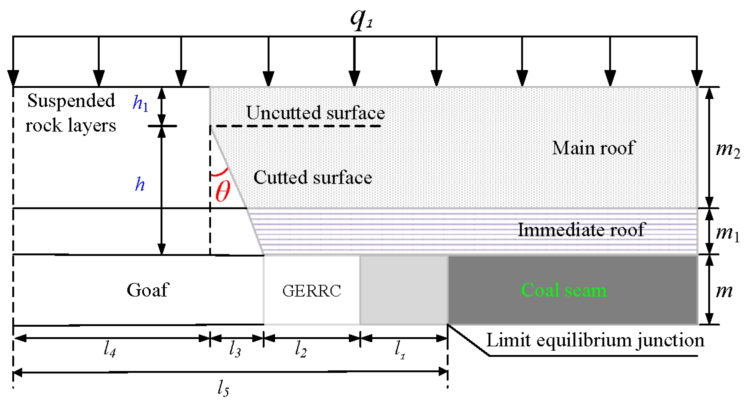
2.2. Quantitative Relationship Analysis of Roof Cutting Parameters for Retaining Roadway

According to [23], it can be concluded that the pre-splitting blasting of the main roof-cutting seam section of the top-cutting and retaining roadway not only ensures the formation of seams along the direction of the blast hole connection but also ensures the stability of the roadway roof. A main dynamic static coupling mechanical model was established, and with the 7135 working face of Qidong Coal Mine as the engineering background, the minimum quantitative relationship between the length of the charge and the spacing between the blast holes during the basic roof formation and the maximum quantitative relationship between the length of the charge and the spacing between the blast holes during the basic roof stability of the roadway were obtained. Based on this, the parameters for advanced pre-splitting blasting in the return airway of the 7135 working face were designed, including the length of the charge and the spacing between the blast holes.
The parameters of roof-cutting angle and height directly affect the distribution of mining-induced stress on the roof during the retention period and the collapse of the goaf roof. Due to the variability in the thickness of the roadway roof, the design of roof-cutting parameters depends not only on the rock type of the roof but also on its thickness. In areas where the immediate roof is thicker and the main roof is thinner, based on the crushing and swelling characteristics of the immediate roof, the roadway roof should be supported before the main roof reaches the maximum span, and the cutting height should equal the thickness of the immediate roof. In areas where the immediate roof is thinner and the main roof is thicker, it is necessary to consider the cutting height and angle to ensure that the main roof completely collapses along the cutting seam surface. In this case, the activity of the rock strata in the goaf includes the fragmentation and subsidence of the direct roof and the breaking and sinking of the basic roof. The main role in stabilizing the roof of the retained roadway is whether the main roof is completely fractured along the cutting line direction. Consider the roof plate as a “cantilever beam” structure [24] with an angle of θ between the cutting seam and the vertical direction, and a height of h to cut off the roadway roof. The load q1 of the overlying rock layer borne by the main suspended roof acts as a uniformly distributed force on the roof q1 of the cantilever beam, and a mechanical model is established as shown in Figure 2.
After mining the working face, the advanced pre-cracked roof begins to collapse under the action of mining stress and self-weight. In order to ensure that the main roof of the uncut joint collapses along the direction of the cutting roof line, the tensile strength of the rock mass is used as the fracture criterion for the main roof of the uncut joint along the cutting roof line. This criterion is:
σ nt > σ t
σ nt = M nt W nt
where M n t is the bending moment at the main roof of the uncut joint, N·m; and W n t is the bending section coefficient at the main roof of the uncut joint. This is expressed as:
{ M nt = q 1 l 4 2 + ρ 2 g m 2 l 4 2 2 W nt = h 1 2 6
where q 1 is the load on the overlying rock layer borne by the basic roof, N/m; l 4 is the distance from the uncut part to the end of the cantilever beam, m; ρ 2 is the density of the basic roof rock layer, kg/m3; m2 is the thickness of the basic roof, m; and h1 is the height of the basic roof of the uncut part, m.
According to Equation (4), l 4 and h1 can be calculated as:
{ l 4 = l 5 l 1 l 2 l 3 h 1 = m 1 + m 2 h
where m1 is the immediate roof thickness, m; h is the cutting top height, m; l1 is the width of the limit equilibrium zone, m; l2 is the width of the roadway, m; l3 is the horizontal projection distance of the cutting top line, m; and l5 is the distance from the limit equilibrium zone to the end of the cantilever beam, m.
Determining l5 from Equation (5), the distance from the limit equilibrium point to the end of the cantilever beam is:
l 5 = l ( l 2 S 2 + 3 2 l S )
where l is the main roof cycle pressure step distance, m; and S is the length of the working face, m.
The tensile stress of the uncut part obtained by substituting Equation (3) into Equation (2) is:
σ nt = 3 q 1 l 4 2 + 3 ρ 2 g m 2 l 4 2 h 1 2
According to the on-site geological conditions, the selected parameters are as follows: l1 = 4.0 m, l2 = 5.0 m, l 3 = h tan θ , l = 17 m, S = 180 m, q = 0.15 MPa, and ρ 2 = 2500 kg/m3. By substituting the above equation, the relationship between the tensile stress of the uncut part and the height and angle of the cut top can be obtained:
σ nt = ( 0.45 + 0.075 m 2 ) ( 10.3 h tan θ ) 2 ( m 1 + m 2 h ) 2
According to Equation (7), after inputting the relevant parameters, the relationship between different main roof thicknesses, top-cutting heights and angles, and tensile stress can be obtained as shown in Figure 3.
As shown in Figure 3, (1) there was a negative correlation and then a positive correlation between the tensile stress and the cutting angle of the non-cut main roof with different main roof thicknesses and all top depths. Within a range of 30° angles of roof cutting, as the top-cutting angle decreased, the tensile stress on the main roof of the uncut joint increased. When the roof cutting angle was 0, the tensile stress on the main roof of the uncut joint reached its maximum. However, in order to facilitate on-site construction and reduce the disturbance of the goaf side roof on the roadway roof, a certain angle needed to be deflected towards the cutting joint surface. The most common angle on site is 10–20° [24]. As the cutting height increased, the tensile stress of the uncut main roof was greater than the allowable range of the ultimate tensile strength of the main roof (4.2 MPa). The range of cutting angles increased with the increase in cutting height; that is, as the cutting height increased, the limitation of the cutting angle on the cutting height became less.
(2) Under different main roof thicknesses and the same top angle conditions, the greater the cutting height, the greater the tensile stress generated on the main roof of the uncut surface, and the better the cutting effect. As the thickness of the main roof increased and changed, the tensile stress on the main roof of the uncut surface was greater than the allowable cutting depth of the main roof’s ultimate tensile strength (4.2 MPa), which increased accordingly. This means that there was a minimum cutting height required to ensure that the main roof of the uncut surface fractured along the cutting line.

3. Analysis of Pressure Relief Effect of Cutting Top Parameters

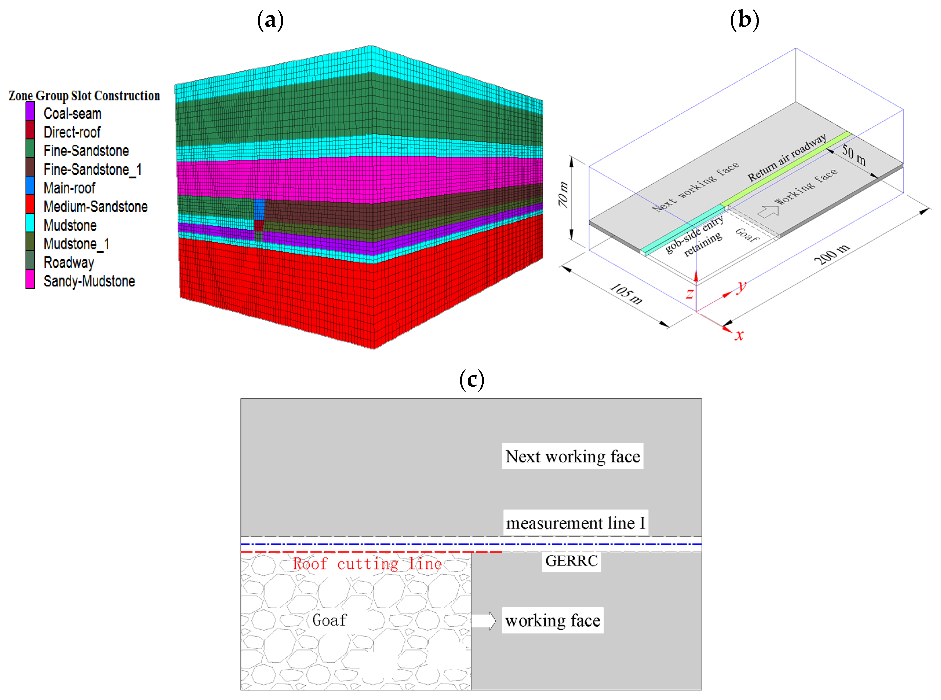
3.1. Model Establishment

The numerical calculation was carried out using FLAC 3D6.0 software, and the Mohr Coulomb constitutive model was used for numerical analysis. A calculation model was established according to the 7135 working face conditions, with dimensions of 200 m in length, 105 m in width, and 70 m in height. The mining thickness was 3.3 m, the thickness of the roof rock was 44.7 m, the thickness of the bottom rock was 22 m, and the dip angle of the coal seam was 0°. The numerical simulation model is shown in Figure 4a. The width of the working face was 100 m, half of which (50 m) was taken. The numerical simulation model had a total of 452,480 grid points and 433,500 zones. Displacement of the bottom, front, back, left, and right sides of the model was fixed. Vertical stress was uniformly applied at the top of the model. For every 100-m increase in depth, the vertical stress increased by 2.5 MPa. Due to the fact that the main purpose of this numerical simulation was to assess the pressure relief effect of different roof-cutting parameters, the working face and roadway roof were treated without support during the excavation period of the model.
When mining, GERRC was implemented in the return air roadway, with a cross-sectional size of 5 m (width) × 3.3 m (height), as shown in Figure 4b. To obtain the Strike stress characteristics of the roadway roof, stress measurement lines were arranged in the middle of the roadway, referred to as measurement line Ⅰ, as shown in Figure 4c.
In the numerical model, solid elements were used for each rock layer, and the physical and mechanical parameters of each rock layer and support structure are shown in Table 1. During the simulated excavation of the working face, the goaf was treated using an unfilled method afterwards. The interface structural element was used to represent the cutting seam surface in the analysis. By assigning normal stiffness and shear stiffness parameters to the structural element, the contact effect after cutting was obtained, as shown in Table 2.

3.2. Pressure Relief Effect of Different Top Cutting Parameters

To adhere to the engineering conditions of the return air roadway in the 7135 working face of Qidong Coal Mine, the top-cutting angle was controlled to remain unchanged at 10°, while the roof-cutting heights were set to 7 m, 9 m, and 11 m, respectively. In Flac3D numerical calculation, the stress value “−” represents compressive stress, and “+” represents tensile stress. Therefore, the maximum principal stress reflects the degree of stress relief caused by mining, while the minimum principal stress reflects the degree of stress concentration caused by mining.

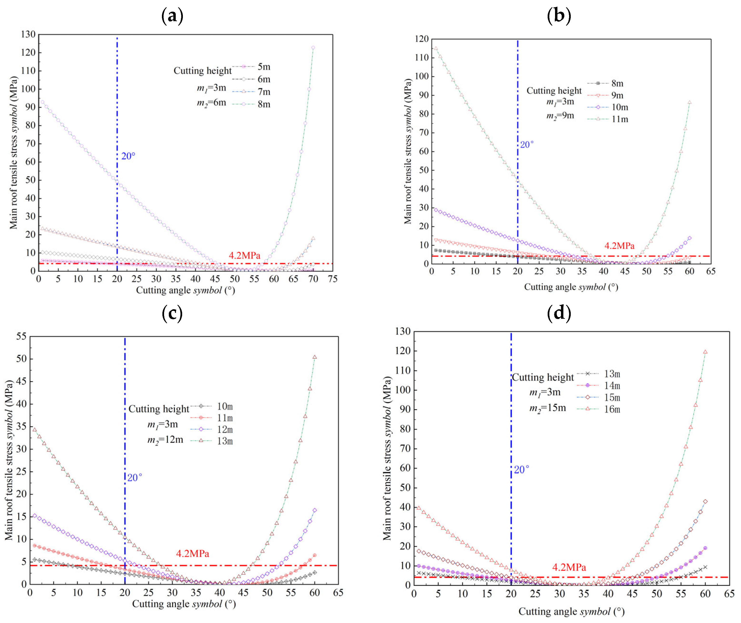
3.2.1. Pressure Relief Effect of Roof-Cutting Height

Figure 5 shows the distribution curves of the maximum and minimum principal stresses at a roof-cutting height of 9 m in the reserved roadway along the working face direction when the working face was mined for 100 m. Point 0 on the horizontal axis indicates the position of the working face. According to Figure 5a, it can be seen that in the advanced working face, different cutting depths have a relatively small impact on the change in maximum principal stress of the roadway roof, indicating that the pressure relief effect of the roadway roof at different cutting depths in the advanced working face is relatively small. During the period of GERRC, as the distance between the lagging working face increased, the distribution of the maximum principal stress on the roof of the retention roadway varied with different roof-cutting heights. When the lagging working face was between 20 m and 60 m, the difference in the maximum principal stress of the retention roadway roof at different roof-cutting heights increased. This is demonstrated by the fact that the maximum principal stress was the smallest at a roof-cutting height of 9 m, at 3.3 Mpa. This was 0.8 MPa and 0.5 MPa lower than the 4.1 MPa and 3.8 MPa observed at a roof-cutting height of 7 m and 11 m, respectively. Therefore, when the roof-cutting height is 9 m, the pressure relief effect of the retained roadway roof is the best.
According to Figure 5b, it can be seen that in the advanced working face, different cutting heights have a relatively small impact on the minimum principal stress of the roadway roof, indicating that different cutting angles have a relatively small impact on the concentration of mining stress in the roadway of the advanced working face. The minimum principal stress was the smallest when the lagging working face was 0–20 m and the cutting height was 7 m. As the distance between the lagging working face increased, the distribution difference of the minimum principal stress was obvious. When the lagging working face was 20–60 m and the cutting height was 9 m, the minimum principal stress was 2.3 MPa and 0.9 MPa smaller than the cutting height of 7 m and 11 m, respectively. Therefore, when the cutting height is 9 m, the concentration of mining stress on the roof of the reserved roadway is the smallest.
Comparing the distribution patterns of maximum and minimum principal stresses under different top-cutting heights, it can be concluded that when a roof-cutting height of 9 m is selected, compared to the top-cutting depths of 7 m and 11 m, there is a better unloading effect on the retained roadway roof, effectively reducing the concentration of mining stress on the retained roadway roof.

3.2.2. Pressure Relief Effect of Roof-Cutting Angle

The roof-cutting height was controlled to 9 m, the roof-cutting angle parameters were increased to 70° and 90°, respectively, and the pressure relief effect of the left roadway roof was analyzed under different roof-cutting angles. The distribution of maximum and minimum principal stresses at 9 m of the roadway roof under different cutting angles is shown in Figure 6.
Under different roof-cutting angles, the distribution of maximum principal stress on the roof of the advanced working face roadway showed little variation, indicating that the pressure relief effect was not significant under different roof-cutting angles, as shown in Figure 6a. The variation pattern of the maximum principal stress on the top plate of the roadway with different top-cutting angles in the lagging working face was similar, and the difference was significant. At a distance of 60 m from the lagging working face, the maximum principal stress at a roof-cutting angle of 80° was 3.3 MPa, which was 0.5 MPa and 1.9 MPa lower than the 3.8 MPa and 5.2 MPa at a roof-cutting angle of 70° and 90°, respectively.
Figure 6b reflects the minimum principal stress distribution of the roof of the roadway with different cutting angles in front of the working face. The influence of different roof-cutting angles on the distribution of minimum principal stress in the advanced working face was relatively small, whereas the variation of minimum principal stress in the lagging working face was relatively large. This is manifested in the range of 10 m to 60 m in the lagging working face. The minimum principal stress in the roof plate of the retained roadway at different roof-cutting angles showed a fluctuating pattern. When the roof cutting angle was 80°, the minimum principal stress in the roof plate of the retained roadway was 12.8 MPa, which was 2.2 MPa and 3.7 MPa lower than that at 70° and 90°, respectively.
Based on the distribution patterns of maximum and minimum principal stresses on the roof of the retained roadway under different cutting heights and angles, it can be concluded that when the cutting angle is 80°, the pressure relief effect of the retained roadway roof is significantly better than that of the cutting angles of 70° and 90°. The quality of the pressure relief effect directly affects the difficulty of maintaining the roadway roof. Taking the 7135 working face of Qidong Coal Mine as the engineering background, when the cutting height is 9 m and the cutting angle is 80 °, the pressure relief effect of the roadway roof is most obvious, and the concentration of mining stress on the left roadway roof is the smallest, which is more conducive to the maintenance of the roadway roof.

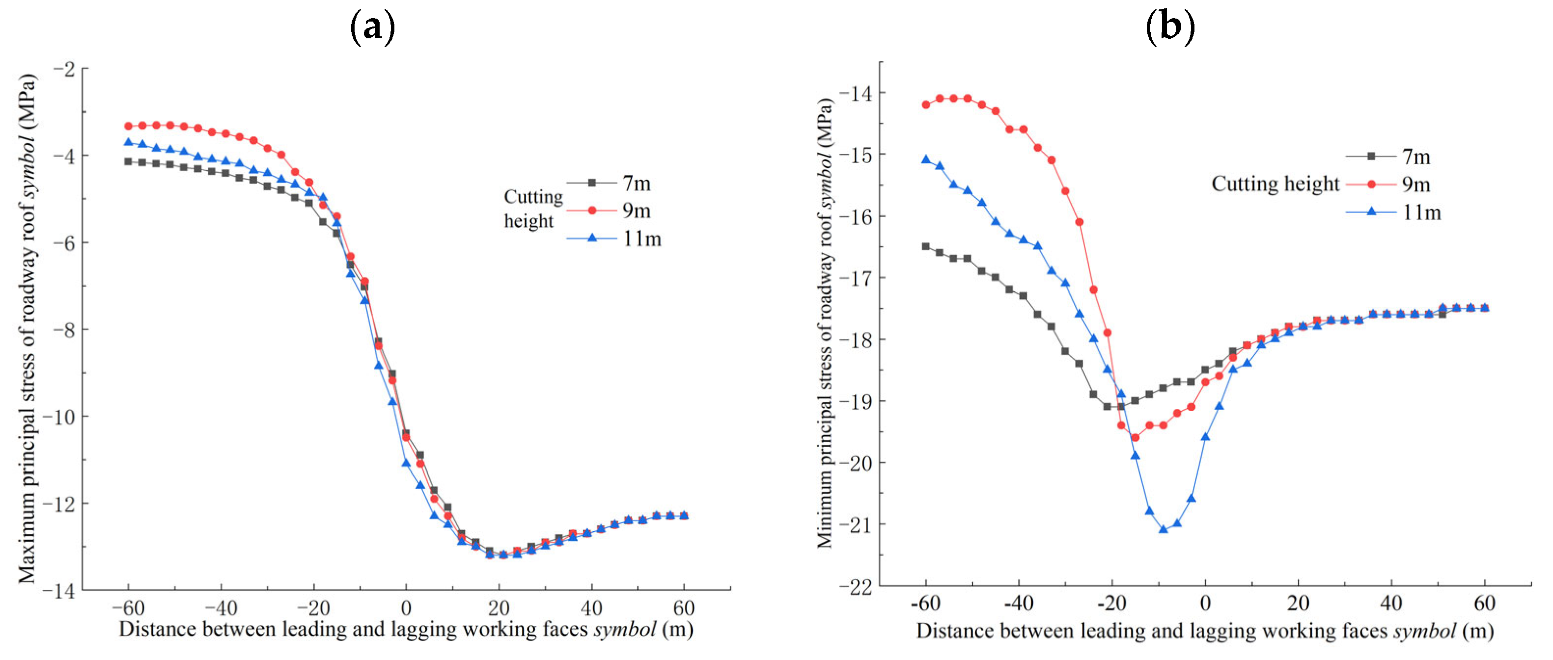
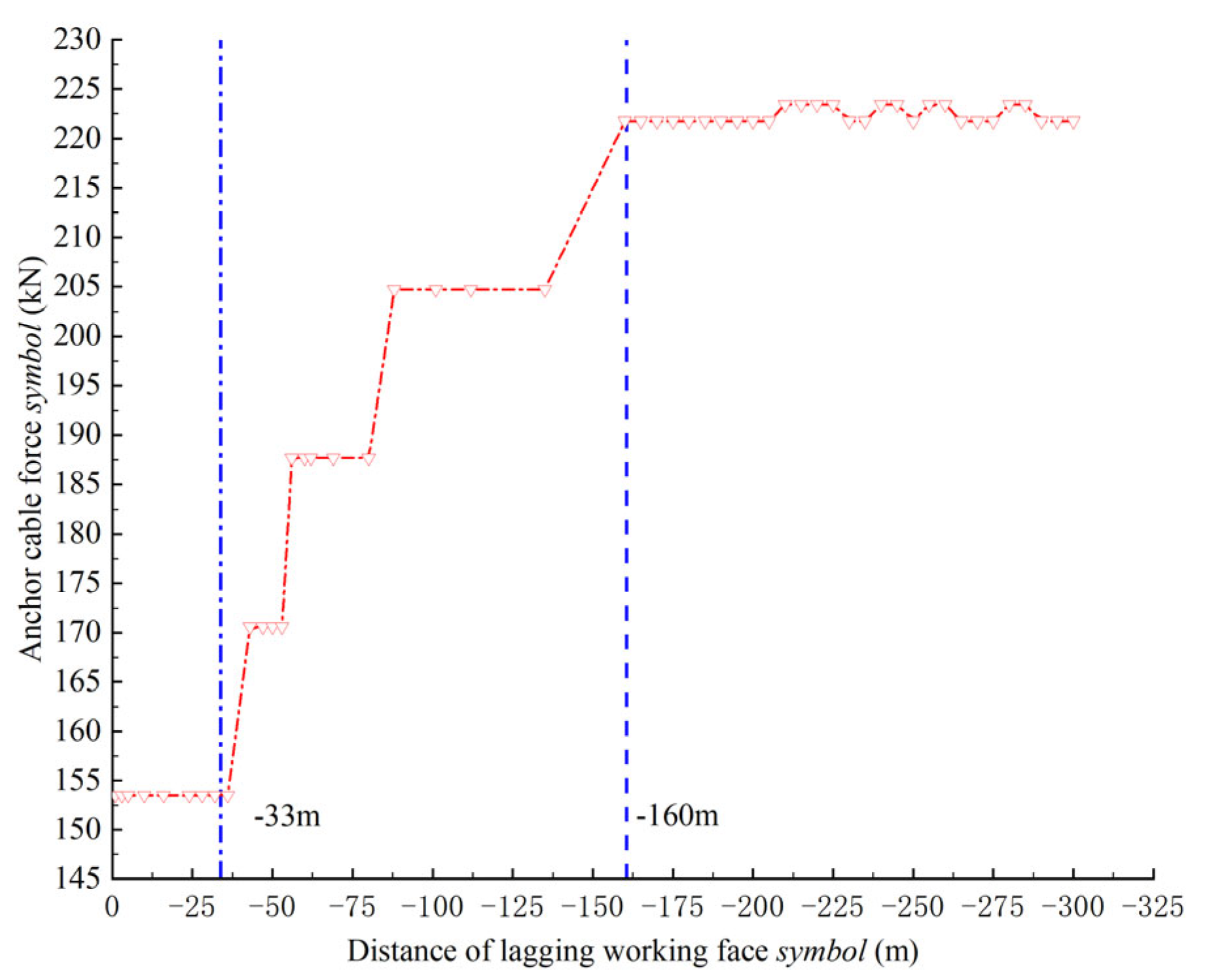
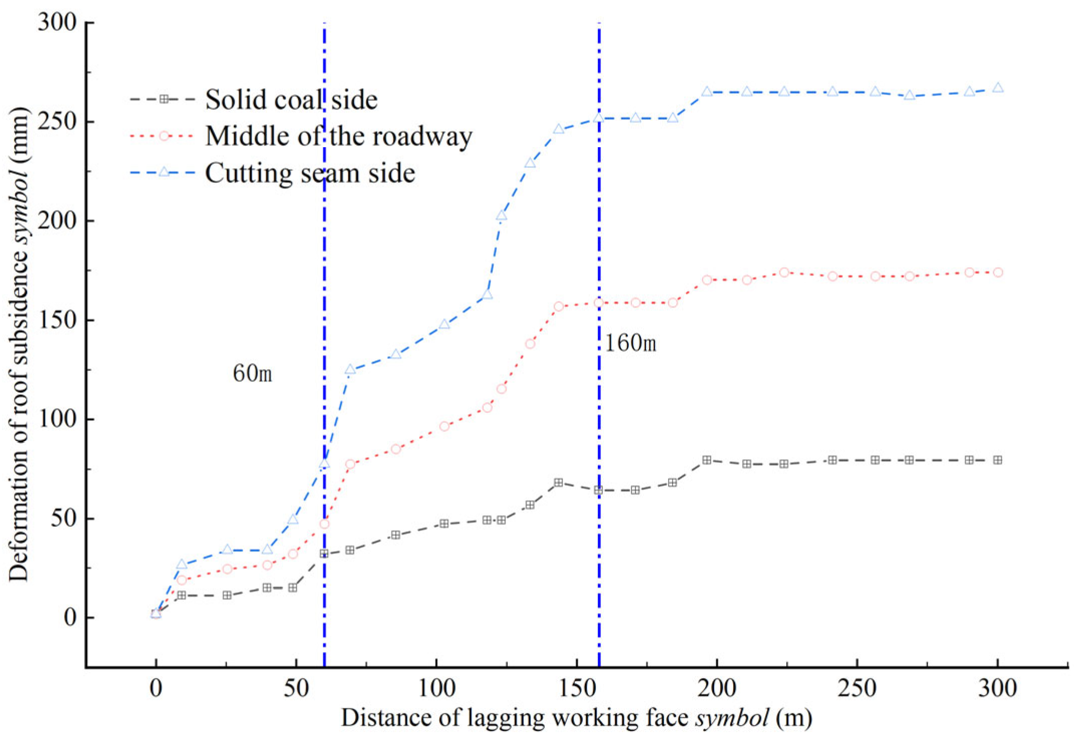
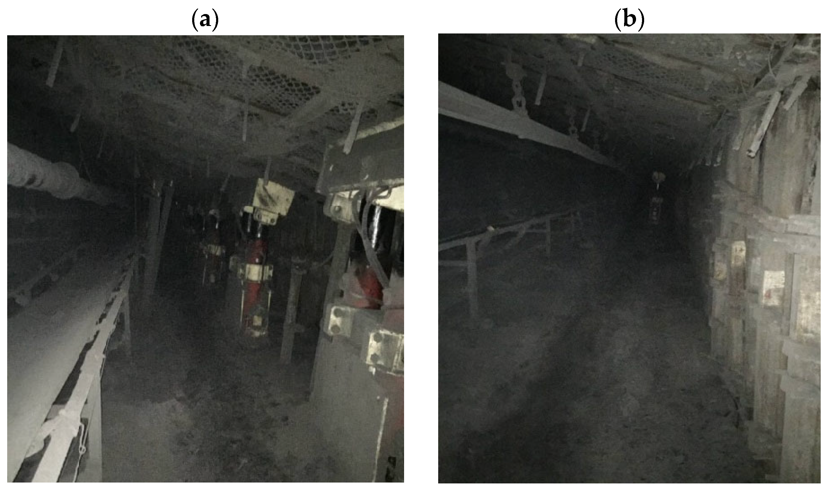
4. Verification of Pressure Relief Effect of Roof Cutting and Roadway Retention

Advanced pre-splitting blasting of the 7135 working face was implemented at the boundary of the roof plate in air return roadway, with a cutting height of 9 m, an angle design of 80° in the horizontal direction, a spacing of 0.6 m between blast holes, a charging length of 4 m, and a sealing depth of 2 m. Pre-splitting blasting was carried out at a height of 50–60 m in advance of the working face using a concentrated energy blasting process. The 7135 working face only tested a 334-m section without coal pillars, and the lagging working face roadway support adopted an “anchor mesh cable + reinforced anchor cable support + temporary stack support”, as shown in Figure 7.
The roof anchor rod support of the roadway adopted threaded steel with a diameter of 20 mm × 2.4 m and a spacing of 0.8 m × 0.8 m. The anchor cable was made of steel strands with a diameter of 21.6 mm × 10.3 m, and the step arrangement was 1.5 m × 1.6 m. The stacked support adopted double-row support, and the specification parameters for the reinforcing anchor cables were as follows: steel strands with dimensions of 21.6 mm × 12.3 m, and a single row with a spacing of 800 mm. After stabilizing the roadway, the temporary reinforcement support, namely the stack-type support, was withdrawn.
During the period of retaining the roadway, measurements of stress on the reinforcement anchor cable and deformation of the roadway roof subsidence were taken, as shown in Figure 8 and Figure 9.
In Figure 8, it can be seen that during the retention period, the force on the anchor cable first increased and then stabilized. During the mining retention period, the range of 0–160 m behind the working face was identified as the impact stage of the retained roadway. During this stage, the force on the reinforced anchor cable showed an increasing trend, and the range of 160–300 m behind the working face was identified as the stable stage of the retained roadway. After stabilizing the retaining roadway, the force of the reinforced anchor cable was stabilized at 225 kN, which was 39% of the tensile strength of the anchor cable. The anchor cable was in a good stress state and met the requirements for supporting the retaining roadway roof.
In Figure 9, it can be seen that the top plate sank rapidly after a 60 m lag in the working face, and the movement of the top plate tended to stabilize around 150 m behind the working face. After stabilizing the roadway, due to the withdrawal of the temporary reinforcement support, there was a slight subsidence of the roof, with a maximum subsidence of about 260 mm on the cutting seam side. The position in the roadway remained stable at around 160 mm, and the subsidence on the coal pillar side was the smallest, approximately 80 mm.
The control situation of the roadway roof during the retention period is shown in Figure 10. The stress on the reinforced anchor cables and the deformation of the roadway roof during the comprehensive retention period could be determined. The stability of the roof during the top-cutting retention period was good, and the section of the retained roadway met the usage requirements. This verifies the pressure relief effect of the top-cutting parameters and the rationality of the design.

5. Conclusions

We established a fracture criterion based on tensile strength for the main roof line of the uncut joint and analyzed the quantitative relationship between the height and angle of the cutting roof and the tensile stress of the main roof at the uncut joint. We found that the basic tensile stress at the roof without a cutting seam initially negatively correlated with the cutting angle and then positively correlated. Within a range of 30° angles of roof cutting, as the cutting angle decreased, the tensile stress on the main roof of the uncut joint increased. When the cutting angle was 0, the tensile stress on the main roof of the uncut joint reached its maximum. As the cutting height increased, the limitation of the cutting angle on the cutting height became smaller.
The distribution patterns of maximum and minimum principal stresses along the direction of the roof in the retained roadway under different cutting heights and cutting angles were studied. Under different cutting heights and angles, the distribution patterns of maximum and minimum principal stresses along the direction of the roadway roof during the retention period were similar, and there were differences in the stress values. Taking the 7135 working face of Qidong Coal Mine as the engineering background, when the cutting height was 9 m and the cutting angle was 80°, the pressure relief effect of the roadway roof was most obvious, and the degree of stress concentration in the remaining roadway roof during mining was the smallest.
We measured the stress on the reinforcement anchor cable during the retention period, the deformation of the roadway roof sinking, and the pressure relief control effect of the retention roadway roof. The design depth of the return air roadway in the 7135 working face of the cut roof coal mine was 9 m, and the cut angle was 80° from in horizontal direction. During the retention period, the reinforcement anchor cable was in a good stress state, and the maximum subsidence deformation on the cut seam side of the roof was 260 mm. The stability of the roof was good, and the cross-section of the roadway met the requirements for use. This verifies the pressure relief effect of the cutting parameters and the rationality of the design.

Author Contributions

Methodology, X.L. and X.H.; Software, X.Q.; Formal analysis, Y.L.; Investigation, X.Q.; Resources, X.H.; Writing—original draft, X.L. All authors have read and agreed to the published version of the manuscript.

Funding

This research was funded by the National Natural Science Foundation of China (U23A20601, 52374075).

Institutional Review Board Statement

Not applicable.

Informed Consent Statement

Not applicable.

Data Availability Statement

The data used to support the findings of this study are available from the corresponding author upon request.

Acknowledgments

The authors express sincere thanks to the journal editors and anonymous reviewers for their help and beneficial comments on the manuscript.

Conflicts of Interest

The author declares that there are no conflicts of interest.

References

  1. He, M. Theory and engineering practice for non-pillars mining with auto magical entry formation and 110 mining method. J. Min. Saf. Eng. 2023, 40, 869–881. [Google Scholar]
  2. Xu, X.; He, F.; Lú, K.; Wa, D.; Li, L.; Zhai, W. Research on reasonable cutting roof parameters of gob side entry retaining by roof cutting in thick and hard roof. J. China Coal Soc. 2023, 48, 3048–3059. [Google Scholar]
  3. He, M.; Guo, P.; Zhang, X.; Wang, J. Directional pre splitting of roadway roof based on the theory of bilateral cumulative tensile explosion. Explos. Shock Waves 2018, 38, 795–803. [Google Scholar]
  4. Zhai, W.; He, F.; Wang, Z.; Liu, D.; Song, J.; Wu, Y.; Xu, X. Research on the effect of roof cutting and surrounding rock control in narrow coal pillars along goaf coal roadway in fully mechanized top coal caving of ultra-thick coal seams. J. Min. Saf. Eng. 2024. Available online: https://link.cnki.net/urlid/32.1760.td.20240304.1427.002 (accessed on 2 June 2024).
  5. Kang, H.; Zhang, X.; Wang, D.; Ti, J.; Yi, Z.; Ji, W. Strata control technology and applications of non-pillar coal mining. J. China Coal Soc. 2022, 47, 16–44. [Google Scholar]
  6. Hua, X.; Li, C.; Liu, X.; Guo, Y.; Qi, Y.; Chen, D. Current situation of gob-side entry retaining and suggestions for its improvement in China. Coal Sci. Technol. 2023, 51, 128–145. [Google Scholar]
  7. Gao, Y.; Yang, J.; Wang, Q.; Wang, Y.; He, M. Mechanism of roof presplitting in a non-pillar mining method with entry automatically retained and its influence on the strata behaviors. J. China Coal Soc. 2019, 44, 3349–3359. [Google Scholar]
  8. Yuan, C.; Yuan, Y.; Zhu, C.; Meng, C. Reasonable parameters of roof cutting entry retaining in thin immediate roof and large mining height fully-mechanized face. J. China Coal Soc. 2019, 44, 1981–1990. [Google Scholar]
  9. Zhang, B.; Wang, P.; Cui, S.; Fan, M.; Qiu, Y. Mechanism and surrounding rock control of roadway driving along gob in shallow-buried, large mining height and small coal pillars by roof cutting. J. China Coal Soc. 2021, 46, 2254–2267. [Google Scholar]
  10. Hou, G.; Hu, T.; Li, Z.; Chen, J.; Cui, Y. Effect of cutting roof height on the stability of gob-side retaining roadway with roadside support. J. Min. Saf. Eng. 2019, 36, 924–931. [Google Scholar]
  11. Wei, Q.; Wang, Y.; Yang, J.; Gao, Y.; Hou, S.; Qiao, B. Roof deformation mechanism and control measures of pillarless mining with gob-side entry retaining by roof cutting and pressure relief. Rock Soil Mech. 2020, 41, 989–998. [Google Scholar]
  12. Hu, C.; Wang, J.; He, M.; Wang, X.; Wang, J.; Zhang, Z. Study on key parameters of self-formed roadway without coal pillar by roof cutting and pressure relief in medium and thick coal seam. Coal Sci. Technol. 2022, 50, 117–123. [Google Scholar]
  13. Yang, H.; Li, Y.; Liu, Y.; Cao, S.; Pan, R.; Wang, H.; Wang, B.; Chen, X.; Zhao, X. Structure evolution and stability control mechanism of hard-roof cutting for roadway retaining. J. Min. Saf. Eng. 2021, 38, 766–773. [Google Scholar]
  14. Zhao, M.; Huang, Q.; Zhu, L.; Huang, K.; Qiu, F.; Xi, X. Research on roof structure and support resistance of gob-side entry retaining with roof cutting and non-pillar mining. J. China Coal Soc. 2021, 46, 84–93. [Google Scholar]
  15. Chang, J.; Qi, C.; Xiong, T. Study on pressure relief control technology of surrounding rock around the staggered roof roadway in a deep long wall face. J. Min. Saf. Eng. 2023, 40, 215–223. [Google Scholar]
  16. He, M.; Wu, Y.; Gao, Y.; Tao, Z. Research progress of rock mechanics in deep mining. J. China Coal Soc. 2024, 49, 75–99. [Google Scholar]
  17. Kang, H.; Jiang, P.; Yang, J.; Wang, Z.; Yang, J.; Liu, Q.; Wu, Y.; Li, W.; Gao, F.; Jang, Z.; et al. Roadway sold coal control technology by means of grouting bolts with high pressure –shotereting in synergy in more than 1000 m deep eoal mines. J. China Coal Soc. 2021, 46, 747–762. [Google Scholar]
  18. Cheng, L.; Kang, H.; Jang, P.; Li, W.; Yang, J.; Zheng, Y.; Yi, K. Deformation and failure characteristics and control technology of surrounding rocks in deeply gob-side entry driving. J. China Coal Soc. 2021, 38, 227–236. [Google Scholar]
  19. Su, C.; Gong, P.L.; Kang, H.P.; Li, C.; Yi, K.; Liu, C.; Li, P. Mechanism of roof cutting and pressure relief in gob-side and high-stress roadway in deep mine. J. China Coal Soc. 2020, 37, 1104–1113. [Google Scholar]
  20. Chen, S.; He, M.; Wang, H.; Yuan, G.; Zhao, F.; Guo, Z. Coordination control and stress evolution of surrounding rock of gob-side entry retaining cutting roof in deep mine. J. Min. Saf. Eng. 2019, 36, 660–669. [Google Scholar]
  21. Gao, Y.; Yang, J.; Zhang, X.; Xue, H.; He, M. Study on Surrounding Rock Control of Roadways in Deep Coal Mines Based on Roof Cutting and Pressure Release Technology by Directional Tensile Blasting. Chin. J. Rock Mech. Eng. 2019, 38, 2045–2056. [Google Scholar]
  22. Liu, X.; Hua, X.; Yang, P.; Yang, S.; Ma, Y. A quantitative study on roof dislocation criterion and support parameters of entry retaining by roof cutting in deep mine. J. Min. Saf. Eng. 2021, 38, 1122–1133. [Google Scholar]
  23. Hua, X.; Liu, X.; Huang, Z.; Yang, P.; Ma, Y. Stability mechanism of non-pillar gob-side entry retaining by roof cutting under the coupled static-dynamic loading. J. China Coal Soc. 2020, 45, 3696–3708. [Google Scholar]
  24. He, M.; Ma, Z.; Guo, Z.; Chen, S. Key parameters of the gob side entry retaining formed by roof cutting and pressure release in deep medium-thickness coal seams. J. China Univ. Min. Technol. 2018, 43, 468–477. [Google Scholar]
Figure 1. Roadway layout and geologic histogram of the working face: (a) Geologic histogram. (b) Roadway layout plan.
Applsci 14 06785 g001
Figure 2. Roof mechanics model of gob-side entry retaining by roof cutting.
Applsci 14 06785 g002
Figure 3. Relationship between cutting roof height, angle, and main roof tensile stress: (a) Main roof thickness of 6 m. (b) Main roof thickness of 9 m. (c) Main roof thickness of 12 m. (d) Main roof thickness of 15 m.
Applsci 14 06785 g003
Figure 4. Calculation model of GERRC: (a) Numerical simulation model. (b) Geometric dimensions of 3D models. (c) Layout of displacement measurement lines.
Applsci 14 06785 g004
Figure 5. Variation curve of stress of the roadway roof: (a) Maximum principal stress of the roadway roof. (b) Minimum principal stress of the roadway roof.
Applsci 14 06785 g005
Figure 6. Distribution curve of stress of the roadway strike roof: (a) Maximum principal stress of the roadway roof. (b) Minimum principal stress of the roadway roof.
Applsci 14 06785 g006
Figure 7. Backward working face roadway support section.
Applsci 14 06785 g007
Figure 8. Changes in force on anchor cables in the lagging working face.
Applsci 14 06785 g008
Figure 9. Changes in displacement of top and bottom plates of the lagging working face.
Applsci 14 06785 g009
Figure 10. Effect of roof pressure relief control during the roadway retention period: (a) Backward work facing the support stage. (b) Stable stage of roadway retention in the lagging working face.
Applsci 14 06785 g010
Table 1. Thickness of each rock formation in the numerical model.
Rock
Formation
Formation
Thickness
m
Unit Weight
kN/m3
Bulk Modulus
GPa
Shear Modulus
GPa
Internal Friction Angle (°)Cohesive Force MPaTensile Strength
MPa
Mudstone 7.0024.002.881.5326.001.171.30
Fine sandstone 14.0026.0010.357.7436.003.154.20
Mudstone5.0024.002.881.5326.001.171.30
Sandy mudstone 11.0025.003.601.8929.001.352.10
Fine sandstone 6.2026.0010.357.7436.003.154.20
Sandy mudstone 3.0025.003.601.8929.001.352.10
Coal 3.3014.001.350.6323.000.720.14
Mudstone 2.0024.002.881.5326.001.171.30
Middle sandstone20.0026.009.386.5434.003.133.40
Table 2. Physical and mechanical index of the structural plane element.
StructureShear Stiffness
N/m
Normal Stiffness
N/m
Poisson RatioInternal Friction Angle (°)
Surface1e82e60.2515
Disclaimer/Publisher’s Note: The statements, opinions and data contained in all publications are solely those of the individual author(s) and contributor(s) and not of MDPI and/or the editor(s). MDPI and/or the editor(s) disclaim responsibility for any injury to people or property resulting from any ideas, methods, instructions or products referred to in the content.

