Article

Analysis of the Forces and Moments in Canine Bodily Movement with Different Clear Aligners’ Extraction Space Designs

1
Department of Orthodontics, Dental Research Institute, School of Dentistry, Pusan National University, Yangsan 50612, Republic of Korea
2
Department of Oral Pathology, School of Dentistry, Pusan National University, Yangsan 50612, Republic of Korea
3
Dental and Life Science Institute, School of Dentistry, Pusan National University, Yangsan 50612, Republic of Korea
*
Authors to whom correspondence should be addressed.
Appl. Sci. 2024, 14(17), 7619; https://doi.org/10.3390/app14177619
Submission received: 19 July 2024 / Revised: 23 August 2024 / Accepted: 26 August 2024 / Published: 28 August 2024

Abstract

:
This study aimed to optimize space closure efficiency by comparing the forces and moments exerted by different designs of clear aligners (CAs) during the movement of maxillary canines into the premolar extraction space. The forces and moments were measured using a multi-axis force/moment transducer on the maxillary right canine. The CAs were fabricated from thermoformed polyethylene terephthalate glycol. The following four edentulous space designs were tested: the edentulous space was left intact (Group 1); the edentulous space was replaced with a premolar pontic (Group 2); the edentulous space was replaced with a half-sized premolar pontic (Group 3); and the edentulous space was replaced with a rectangular column beam (Group 4). The maxillary right canine was moved 0.25 mm distally. All groups experienced buccodistal and intrusive forces; compared with the other groups, Group 1 showed significantly greater intrusive and smaller distal forces, and Group 4 showed significantly greater distal forces. All groups experienced distal tilting, lingual inclination, and mesial rotational moments. These findings suggest that modifying the thickness and extent of the adjacent teeth in the edentulous area of the CA can improve local stiffness, thereby reducing the tipping of the teeth into the edentulous space. This study emphasizes the importance of the CA design in controlling forces and moments for effective orthodontic treatment.

1. Introduction

Recently, clear aligners (CAs) have become increasingly popular as esthetic appliances and are preferred over conventional fixed appliances. In addition to their esthetic benefits, CAs are removable, which helps in maintaining oral hygiene, and they are less load-bearing than conventional fixed appliances. Previously, CAs were used to treat minor problems, such as relapse and crowding; however, advances in materials and fabrication techniques have expanded their range of applications to more complex and diverse cases [1,2,3,4,5].
Despite the widespread use of CAs, the accuracy is not sufficiently high, and concerns regarding their effectiveness and stability in regulating tooth movements remain [6,7,8]. This could be because of the lack of understanding of how CAs transmit force/moment [9]; unlike in conventional fixed appliances, the point at which force transmission occurs in CAs is still unclear. Unintended tooth movements can occur within the CA, making it difficult to achieve planned tooth movements [4,10].
In particular, torque control, tooth rotation, and bodily movements during tooth movements present many limitations in achieving the planned tooth movements using CAs [8,11,12]. Especially in premolar extraction cases, CAs are not sufficiently rigid to maintain the three-dimensional (3D) shape of the maxillary arch during space closure, which can lead to torque loss and the extrusion of the anterior teeth [13,14]. This often results in a “roller coaster” effect, i.e., distal tilting of the anterior teeth and mesial tilting of the molars associated with anchorage loss, thus exhibiting undesirable results such as insufficient retraction of the anterior teeth and excessive mesial displacement of the maxillary first molars [15]. Therefore, in many CA cases with extractions, the final occlusion presents an undesirable Class II molar relationship. This poses significant challenges for orthodontists during CA treatment. Flexible CA materials are prone to change, especially for space closure, and may not be suitable for bodily movements [15,16].
Various methods have been used to solve the problem of space closure during orthodontic treatment with CA. For instance, a certain amount of intrusion is intentionally added to the incisors when they move posteriorly to control their movement. Unfortunately, the effectiveness of additional intrusion has not been proven, and the most efficient ratio between the amount of posterior movement and intrusion remains unclear [13,14]. Additionally, to solve the problem of anchorage loss in the molars, the use of Class II elastics with CAs has been proposed [17], and attempts have been made to modify the design of CAs for better utilization of the forces and moments applied to the teeth. For instance, modifications in the CA design include adding a power ridge to control the maxillary anterior torque effectively or thickening the buccal side of the CA to increase its stiffness [18]. However, despite these attempts, achieving effective space closure using CAs remains challenging and under-researched.
This study focused on manipulating the design of CAs to efficiently apply forces and moments. In premolar extraction cases, the design of the edentulous area may affect the amount of tooth coverage by the CA adjacent to the edentulous area. For most CAs, the edentulous space acts as a hollow space with the shape of the extracted tooth, which does not provide a sufficiently strong grasp on the tooth adjacent to the extraction space and can affect the stiffness of the CA. Therefore, to grasp the adjacent teeth more firmly and ensure a larger contact area, the following alternatives can be considered: the vertical height of the CA in the edentulous area could be reduced to the alveolar bone level; the width could be reduced to a half-pontic size; or a beam design could be used to increase the stiffness of the CA.
This study aimed to measure and compare the forces and moments generated by different CA designs during the distal bodily movement of maxillary canines into the maxillary premolar extraction space, and to propose a design for more efficient space closure using a miniature six-axis force/moment sensor and a 3D printed customized apparatus.

2. Materials and Methods

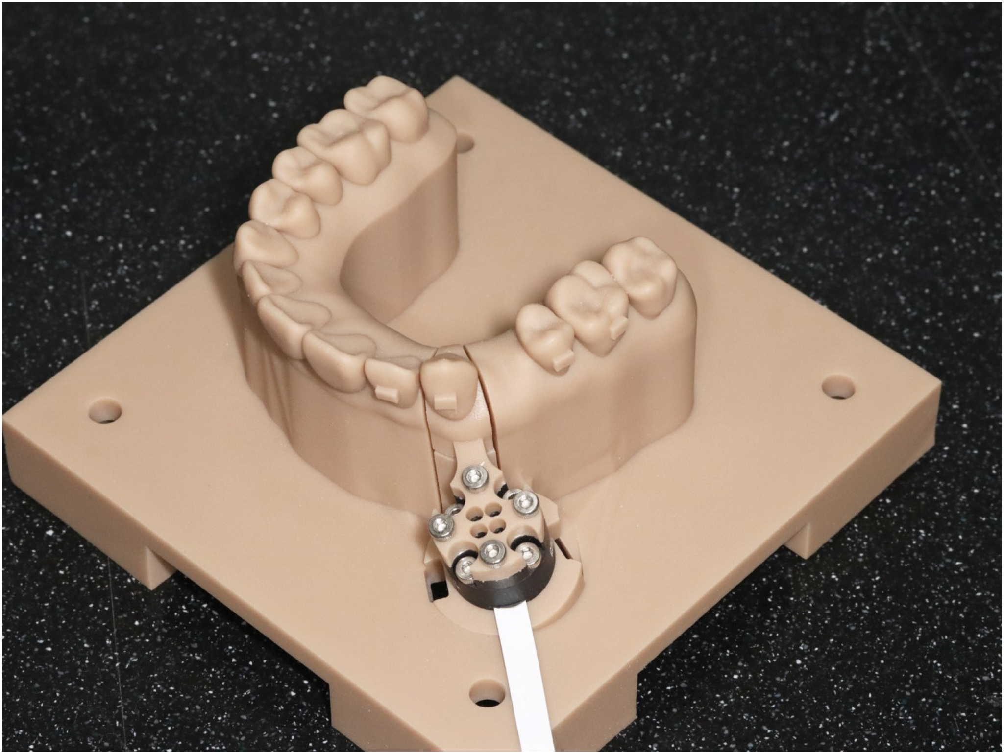
2.1. Forces/Moments Measurement Apparatus Design and Fabrication

The maxillary dentition model was designed using a Nissin dental model (NISSIN B3-305, Nissin Dental Products, Kyoto, Japan) with a 3D scanner (TRIOS 4, 3Shape TRIOS A/S, Copenhagen, Denmark). The model was established with the maxillary right first premolar extracted to simulate the posterior bodily movement of the maxillary right canine.
To measure the forces and moments applied to the maxillary canine by the CA, a force/moment measurement apparatus was designed and 3D printed using an STL file editing program (Meshmixer ver 3.5, Autodesk Inc., San Rafael, CA, USA) to connect a six-axis miniature force/torque sensor (Aidin Robotics, Seoul, Republic of Korea) to the maxillary right canine (Figure 1).
The forces and moments were measured by mounting the thermoforming CA on the apparatus and maintaining it at 37 °C for 10 min using a Forced Convection Incubator (C-INDF, Changshin Science, Busan, Republic of Korea) to reproduce the intraoral environment. Following this, the average values of the measured forces and moments over the next 10 min were used for analysis. The directions of the force and moment on the multi-axis obtained were separated by “+” and “−” signs (Table 1).

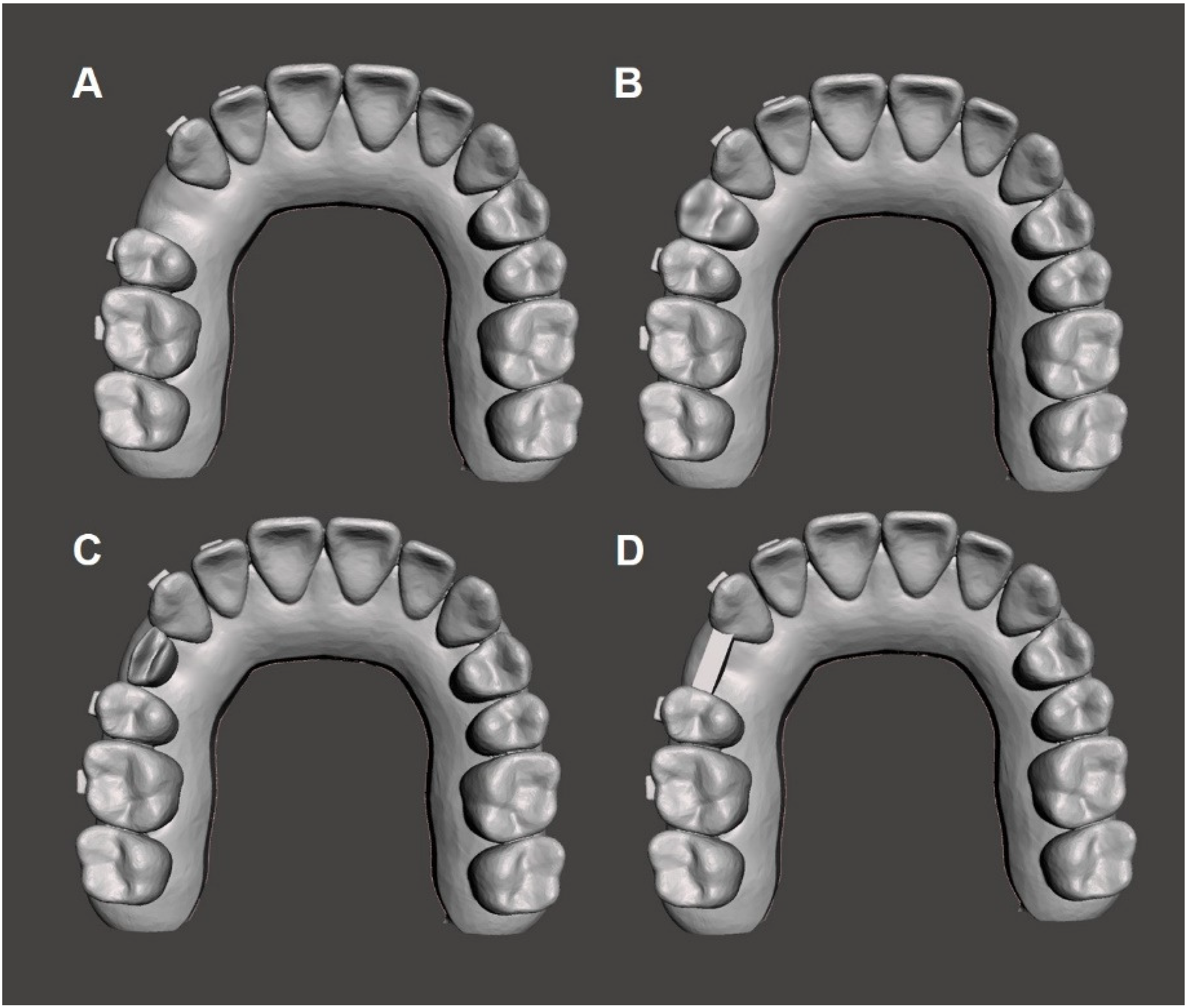
2.2. Design Modification and Fabrication of the Experimental CA for Distal Bodily Movement of the Maxillary Canine

In this study, CAs with four types of edentulous area designs were fabricated to measure the forces and moments on the right maxillary canine during a 0.25 mm posterior bodily movement of the tooth. The 0.25 mm bodily movement simulation of the maxillary canine was modeled using 3D dental software (DentOne ver 1.0, Diorco, Yongin, Republic of Korea). The designs of the four CAs were as follows (Figure 2):
Group 1: 0.25 mm distal bodily movement of the canine;
Group 2: 0.25 mm distal bodily movement of the canine + replacement of the edentulous space with a first premolar pontic;
Group 3: 0.25 mm distal bodily movement of the canine + replacement of the edentulous space with a pontic that is half the buccolingual width of the first premolar (height: original premolar’s height);
Group 4: 0.25 mm distal bodily movement of the canine + replacement of the edentulous space with a beam shape column (height: inferior to the proximal contact point; thickness: half the buccolingual width of the adjacent premolar).
The CAs were fabricated by a thermoforming method using 0.75 mm thick polyethylene terephthalate glycol (Easy-Vac, 3A MEDES, Goyang-si, Republic of Korea). Each experimental group included 33 CAs to account for any losses, resulting in a total of 120 CAs used in the experiment.

2.3. Statistical Analysis

All measured values showed a normal distribution; they are presented as means and standard deviations. To achieve a 0.25 mm distal bodily movement efficiently of the maxillary canine in a first premolar extraction case, a one-way analysis of variance with Tukey’s least significance difference post hoc test was performed to compare the forces and moments generated on the maxillary canine by CAs of different designs in the edentulous region. All analyses were performed using the statistical software R ver 4.3.3; p-values < 0.05 were considered statistically significant.

3. Results

3.1. Multi-Axis Forces and Moments

In this study, the forces and moments generated in the four experimental groups with different CA designs were analyzed. Significant differences (p < 0.001) were observed between the groups for all measured forces and moments (Table 2).
The buccolingual force (Fx) values showed that all groups generated a buccal force. While Groups 2 and 4 exhibited similar Fx values (6.38 ± 2.33 cN and 4.42 ± 2.32 cN, respectively; p > 0.05), Groups 3 and 1 had significantly higher Fx values (7.28 ± 3.05 cN and 20.09 ± 3.88 cN, respectively). The mesiodistal force (Fy) was the highest in Group 4 (5.67 ± 1.19 cN), followed by Groups 2 and 1, and the lowest in Group 3 (1.20 ± 0.90 cN) (p < 0.001). All groups experienced an intrusive force (Fz), with decreasing forces recorded in Groups 1, 4, 3, and 2, in that order; no statistically significant difference was observed between Groups 2 and 3 (p > 0.05).
The angulation moment (Mx) values showed distal tipping moments in all groups, with a mean Mx of −7.66 ± 1.64 (Nmm) in Group 1, and Groups 4, 3, and 2 showing a gradual decrease in the distal tipping tendency. The inclination moment (My) values were measured, and Group 1 showed the largest lingual inclination moment (−17.41 ± 1.88 Nmm), while Group 2 showed the smallest moment (−4.78 ± 2.14 Nmm). The rotation moment (Mz) values showed that all groups had mesial rotation moments, with a decreasing trend from Group 1 to Group 4; no significant difference was observed between Groups 2 and 3 (p > 0.05).
Thus, despite the different edentulous area designs of the CAs, all groups mainly showed buccal and distal bodily movements and intrusive forces, whereas the crowns showed distal and lingual tilting and mesial rotation moments.

3.2. Total Sum of Forces on the X, Y, and Z Axes

The total forces (Fx, Fy, Fz) applied to the canine teeth were measured in the four experimental groups. The Fx, Fy, and Fz vectors were calculated for each group to compare the magnitude and direction of the forces on the canine in three dimensions. The magnitude of the forces was significantly greater in Group 1, but did not differ significantly among Groups 2, 3, and 4. The sum of the vectors was 30.25 cN in Group 1, decreasing in magnitude through Groups 4 and 3, and finally reaching 12.82 cN in Group 2. The direction of force showed buccal, distal, and intrusive movements in all groups. Although Group 1 was subjected to the greatest intrusive (−22.53 cN) and buccal force (20.09 cN), it experienced a mild distal force (191 cN), which resulted in the tooth being intruded and tending to move buccally. Group 2 was subjected to a relatively small intrusive force (−10.65 cN), a moderate buccal force (6.38 cN), and a distal force (3.43 cN), which caused the teeth to be both intrusively and buccally displaced, but more distal than in Group 1. In Group 3, the teeth had a tendency to intrude and move buccally, exhibiting the least distal movement among the four groups. Group 4 also showed intrusive and buccal forces but had the largest distal force.

4. Discussion

This study measured the forces and moments generated by CAs of different designs on the canine during its distal bodily movements using the six-axis force/moment sensor introduced by Grant et al. [19]. By measuring the forces and moments, the biomechanics of CAs can be clearly revealed, and an optimized design of the edentulous area for the bodily movements of the canine can be proposed.
The thermoplastic material, CA, exhibits viscoelastic behavior, i.e., it has elastic and plastic properties [16]. Therefore, in distal bodily movements of the canine using a CA, the elastic deformation of the CA can cause the distal tilting and rotation of the canine. If the elastic energy is well transferred to the canine, the canine can become upright and undergo distal bodily movement [20]. To achieve this, a large contact surface between the CA and the tooth is required, and attachments are often used [21]. When attachments are used, the attachment shape does not have a significant effect on efficiency [21,22]; however, it has been reported that without attachments, teeth can easily tip and rotate [9]. Therefore, rectangular attachments were used for the canines in this study [23].
This study used four types of CAs to simulate the distal bodily movements of canines. The results showed that, in all groups, the canines tended to move by intrusion in the buccal and distal directions, although the magnitudes of the forces and moments differed with the different designs of the edentulous region. These results are consistent with those of a study by Yongjie et al., which showed that when a canine is subjected to distal forces, it is subjected to extrusion and lingual forces initially when the canine is inclined proximally; however, after the canine is upright, buccal and intrusion forces predominate [24]. Although the main force is applied on the proximal side of the canine, the irregularity of the contact surface between the tooth and the CA may cause the vector to vary in three dimensions. However, when only the CA design is modified in the edentulous area, as carried out in this study, the directionality of the forces and moments does not seem to be affected.
Furthermore, differences in the magnitudes of the forces and moments were observed. Group 1 exhibited the largest forces, mainly intrusive and buccal forces, and relatively weak distal forces, while Group 4 exhibited the largest distal forces with moderate intrusive and buccal forces. Groups 2 and 3 exhibited moderate forces in all three dimensions. The distal force values for all groups were within the range of optimal intrusive forces (10–20 cN) [25]. It is considered that Group 1 generated strong intrusive forces, and the possibility of the CA being off the track was much higher than in the other experimental groups as the tooth movement progressed. Although we simulated 0.25 mm of distal bodily movement in all groups, the distal force on the canine located at the corner of the dental arch was significantly smaller than the intrusive force.
The contact between the CA and the tooth is important in determining the forces that the CA generates on the tooth. Upadhyay and Arqub reported that close contact between the CA and the tooth helps distribute stress more uniformly across the tooth surface [26]. Elshazly et al. reported that the contact between the CA and the tooth surface is important in determining the distribution of forces [27]. These contacts are affected by the manufacturing method and material of the CA. Moreover, environmental factors, such as intraoral humidity and temperature, can cause changes in the material properties, changing the stiffness of the CA and affecting the contact [28]. The setting of the contact of the CA with the distal surface of the tooth can affect the distribution of distal forces even if the contact at the proximal surface of the tooth is the same, as was the case in this study. Unfortunately, although this experiment attempted to reduce this effect using a rectangular attachment, it was difficult to reduce the overall intrusive force. In particular, Group 1, which utilized a shape that covers both the buccal and distal surfaces of the tooth, exhibited strong intrusive forces.
Kawamura et al. analyzed the forces and moments on the canine using the finite element method (FEM) after subjecting it to a distal bodily movement of 0.1 mm with the CA [23]. The results showed that most of the contact between the CA and the canine occurred on the mesial side of the canine. They also reported that distal forces and mesial tipping moments were generated on the canine, regardless of the presence and type of attachment. However, our study showed a contrasting result, with the distal tipping moment occurring in all groups, regardless of the design of the edentulous area. Additionally, the distal force applied to the canine in the previous study was approximately 370–390 cN [23], which was 12–30 times greater than the total force vector in our study (12.82–30.25 cN). This is a significant difference considering that the movement of the canines in our study was 0.25 mm and that in the FEM analysis was 0.1 mm. These differences could be attributed to the simulation in the FEM analysis. To activate the CA, the FEM analysis was performed by translating the canine 0.1 mm in the mesial direction while the canine and CA were passively mounted, storing the stresses generated by the CA and applying them to the movement of the canine to analyze the stresses on the canine. Because of this simulation method, the FEM study showed a slight extrusion force, and the majority of the contact force was generated on the proximal surface of the canine and the inferior surface of the attachment [23], which may have caused the distal force and mesial tipping moment of the canine. However, in our study, the CAs were actually inserted into and removed from the force/moment sensor apparatus; therefore, they were not initially passively mounted, resulting in an intrusive force rather than an extrusive force, and the distal tipping moment of the tooth occurred in all groups. Another possible reason for the inconsistency between the FEM analysis and this study is the material properties, i.e., the viscoelasticity of the material, thickness of the material, and experimental conditions [29]. The FEM analysis assumed the CA to be an isotropic, homogeneous, and linearly elastic material of constant thickness, which is not the case in actual practice. Moreover, since the CA is fabricated by vacuum thermoforming, it is difficult to have a uniform thickness on the tooth surface; moreover, the thickness is relatively thin in the cervical region [30], thus explaining the inconsistencies between the studies.
The distribution and point of action of the forces generated by a CA on a tooth depend on the type of tooth movement, i.e., bodily movement or tipping movement. In particular, bodily movement requires a greater force to be applied at the cervical region than at the incisal region [31]. However, in thermoformed CA, the cervical region is the most vulnerable region due to deformation and irregularities [32,33]; hence, it is challenging to apply a greater force at the cervical region than at the incisal region using a CA. To overcome these limitations, modifications in procedural protocols [34] and improvements in auxiliary tools and materials have been attempted [35,36]. Treatment with auxiliary tools, such as attachments, power arms, and mini-implants, has been widely applied. However, the excessive use of auxiliary tools makes it difficult to insert and remove CAs, and the power arms are attached to the cervical region, resulting in a severe foreign body sensation and poor esthetics. Although improving the CA material to improve force transmission and reduce stress relaxation has achieved some success, it is limited by the difficulty of balancing stiffness and elasticity [36,37].
Therefore, instead of using the methods attempted in previous studies, the design of the edentulous area, i.e., morphometric change (distal cervical area), was modified in this study to increase the contact area between the CA and the canine while simultaneously changing the elasticity and stiffness of the material in the localized area of the CA to control the forces and moments generated on the canine [38,39]. When there was a posterior extraction space, Group 1 grasped the three sides of the canines the most, followed by Group 4 with the beam structure, and then by Groups 3 and 2. However, these contact areas refer to when the CA is mounted passively on the dentition; hence, the contact area between the tooth and the CA is different for active aligners that are set to allow 0.25 mm bodily movement of the maxillary canines, as in this study. Groups 2 and 3, which had similar morphologies, were more similar than Groups 1 and 4, which had different force and moment values. However, for the buccolingual tilting moment (My) value, Group 3 showed a larger lingual tilting moment than that of Group 2. This is probably due to the increased stiffness in the pontic region of Group 3 due to the difference in the pontic space of the edentulous area between the groups. According to Hahn et al. [29], there is a correlation between the CA thickness and the forces transmitted by the CA. As the thickness of the CA increases in the interproximal space, the tensile stresses generated in these regions are enhanced [40]. Similarly, in Group 3, because the pontic was one-half the width of the maxillary first premolar, the closeness between the buccolingual CA and the cervical region may have increased the stiffness, similar to increasing the thickness. Therefore, it is assumed that Group 3 transmitted a stronger force to the cervical region than did Group 2, resulting in an increased lingual tilting moment.
Although distal tipping moments occurred regardless of the edentulous area design, they were not substantial (range, 0.22–7.66 Nmm). Notably, the distal tipping moment and lingual tilting moment tended to increase with the distal surface contact area between the CA and the canine, being the largest in Group 1, followed by Groups 4, 3, and 2. This is probably due to a wider contact area, such as in Group 4, where the point of action of the force is not only on the proximal surface of the canine, but also on the distal cervical area, and the opposite direction of the force is easily transmitted, resulting in a large rotational moment while wearing the CA. Group 4 showed adequate intrusive force and significantly larger distal force than the other groups, and it is considered the most appropriate design for the edentulous area when attempting distal bodily movements of the canine.
This study has several limitations. Because we measured and compared the initial forces and moments generated by the CA on the teeth, we could only describe the initial effect when analyzing the force system of the orthodontic appliance and could not determine the changes in the orthodontic forces over time. Moreover, the biomechanical effects of the attachment position on the tooth were not evaluated; the shape of the attachment and the attachment position on the tooth surface can affect the forces and moments. Finally, as the forces and moments of only a single tooth were examined, they did not accurately reflect the actual orthodontic treatment scenarios, wherein multiple teeth move simultaneously, nor did they consider the effects of masticatory movements and occlusal forces following the use of CAs. Therefore, complementary preclinical evaluation studies and biomechanical studies are warranted to investigate the efficacy during actual orthodontic treatment.

5. Conclusions

This study compared the forces and moments generated on the canine during its distal bodily movement by different designs of the CA in the edentulous region when closing the maxillary premolar extraction space, and identified an efficient design for space closure. We found that changing the thickness of the edentulous part of the CA or increasing the contact surface by increasing the coverage of the adjacent teeth in the edentulous area strengthened the local stiffness of the CA and reduced tooth tilting toward the edentulous area. These results may be applied clinically as a new anchorage preparation method during CA treatment.

Author Contributions

Conceptualization, Y.-K.C., S.-S.K., and Y.-I.K.; methodology, Y.-K.C., H.R.P., S.-H.K., and S.-S.K.; formal analysis, Y.-K.C., H.R.P., S.-H.K., S.-S.K., and Y.-I.K.; writing—original draft preparation, S.-S.K., Y.-K.C., and Y.-I.K.; writing—review and editing, Y.-K.C., H.R.P., S.-H.K., S.-S.K., and Y.-I.K.; funding acquisition, S.-S.K. All authors have read and agreed to the published version of the manuscript.

Funding

This study was supported by the Dental Research Institute (PNUDH DRI-2024-01), Pusan National University Dental Hospital.

Institutional Review Board Statement

Not applicable.

Informed Consent Statement

Not applicable.

Data Availability Statement

The data supporting the findings of this study will be available from the corresponding author upon reasonable request.

Conflicts of Interest

The authors declare no conflicts of interest.

References

  1. Noll, D.; Mahon, B.; Shroff, B.; Carrico, C.; Lindauer, S.J. Twitter analysis of the orthodontic patient experience with braces vs. Invisalign. Angle Orthod. 2017, 87, 377–383. [Google Scholar] [CrossRef] [PubMed]
  2. White, D.W.; Julien, K.C.; Jacob, H.; Campbell, P.M.; Buschang, P.H. Discomfort associated with Invisalign and traditional brackets: A randomized prospective trial. Angle Orthod. 2017, 87, 801–808. [Google Scholar] [CrossRef]
  3. Boyd, R.L. Esthetic orthodontic treatment using the Invisalign appliance for moderate to complex malocclusions. J. Dent. Educ. 2008, 72, 948–967. [Google Scholar] [CrossRef] [PubMed]
  4. Rossini, G.; Parrini, S.; Castroflorio, T.; Deregibus, A.; Debernardi, C.L. Efficacy of clear aligners in controlling orthodontic tooth movement: A systematic review. Angle Orthod. 2015, 85, 881–889. [Google Scholar] [CrossRef] [PubMed]
  5. Boyd, R.L.; Waskalic, V. Three-dimensional diagnosis and orthodontic treatment of complex malocclusions with the Invisalign appliance. Semin. Orthod. 2001, 7, 274–293. [Google Scholar] [CrossRef]
  6. Haouili, N.; Kravitz, N.D.; Vaid, N.R.; Ferguson, D.J.; Makki, L. Has Invisalign improved? A prospective follow-up study on the efficacy of tooth movement with Invisalign. Am. J. Orthod. Dentofac. Orthop. 2020, 158, 420–425. [Google Scholar] [CrossRef]
  7. Zhou, N.; Guo, J. Efficiency of upper arch expansion with the Invisalign system. Angle Orthod. 2020, 90, 23–30. [Google Scholar] [CrossRef]
  8. Kravitz, N.D.; Kusnoto, B.; BeGole, E.; Obrez, A.; Agran, B. How well does Invisalign work? A prospective clinical study evaluating the efficacy of tooth movement with Invisalign. Am. J. Orthod. Dentofac. Orthop. 2009, 135, 27–35. [Google Scholar] [CrossRef]
  9. Jiang, T.; Wu, R.Y.; Wang, J.K.; Wang, H.H.; Tang, G.H. Clear aligners for maxillary anterior en masse retraction: A 3D finite element study. Sci. Rep. 2020, 10, 10156. [Google Scholar] [CrossRef]
  10. Zhang, X.J.; He, L.; Guo, H.M.; Tian, J.; Bai, Y.X.; Li, S. Integrated three-dimensional digital assessment of accuracy of anterior tooth movement using clear aligners. Korean J. Orthod. 2015, 45, 275–281. [Google Scholar] [CrossRef]
  11. Djeu, G.; Shelton, C.; Maganzini, A. Outcome assessment of Invisalign and traditional orthodontic treatment compared with the American Board of Orthodontics objective grading system. Am. J. Orthod. Dentofac. Orthop. 2005, 128, 292–298. [Google Scholar] [CrossRef] [PubMed]
  12. Lombardo, L.; Arreghini, A.; Ramina, F.; Ghislanzoni, L.T.H.; Siciliani, G. Predictability of orthodontic movement with orthodontic aligners: A retrospective study. Prog. Orthod. 2017, 18, 35. [Google Scholar] [CrossRef] [PubMed]
  13. Bowman, S.J. Improving the predictability of clear aligners. Semin. Orthod. 2017, 23, 65–75. [Google Scholar] [CrossRef]
  14. Simon, M.; Keilig, L.; Schwarze, J.; Jung, B.A.; Bourauel, C. Forces and moments generated by removable thermoplastic aligners: Incisor torque, premolar derotation, and molar distalization. Am. J. Orthod. Dentofac. Orthop. 2014, 145, 728–736. [Google Scholar] [CrossRef]
  15. Baldwin, D.K.; King, G.; Ramsay, D.S.; Huang, G.; Bollen, A.M. Activation time and material stiffness of sequential removable orthodontic appliances. Part 3: Premolar extraction patients. Am. J. Orthod. Dentofac. Orthop. 2008, 133, 837–845. [Google Scholar] [CrossRef]
  16. Bichu, Y.M.; Alwafi, A.; Liu, X.; Andrews, J.; Ludwig, B.; Bichu, A.Y.; Zou, B. Advances in orthodontic clear aligner materials. Bioact. Mater. 2023, 22, 384–403. [Google Scholar] [CrossRef] [PubMed]
  17. Dai, F.F.; Xu, T.M.; Shu, G. Comparison of achieved and predicted tooth movement of maxillary first molars and central incisors: First premolar extraction treatment with Invisalign. Angle Orthod. 2019, 89, 679–687. [Google Scholar] [CrossRef]
  18. Cheng, Y.; Gao, J.; Fang, S.; Wang, W.; Ma, Y.; Jin, Z. Torque movement of the upper anterior teeth using a clear aligner in cases of extraction: A finite element study. Prog. Orthod. 2022, 23, 26. [Google Scholar] [CrossRef] [PubMed]
  19. Grant, J.; Foley, P.; Bankhead, B.; Miranda, G.; Adel, S.M.; Kim, K.B. Forces and moments generated by 3D direct printed clear aligners of varying labial and lingual thicknesses during lingual movement of maxillary central incisor: An in vitro study. Prog. Orthod. 2023, 24, 23. [Google Scholar] [CrossRef]
  20. Kojima, Y.; Fukui, H. Numerical simulation of canine retraction with T-loop spring based on the updated moment-to-force ratio. Eur. J. Orthod. 2012, 34, 10–18. [Google Scholar] [CrossRef]
  21. Gomez, J.P.; Peña, F.M.; Martínez, V.; Giraldo, D.C.; Cardona, C.I. Initial force systems during bodily tooth movement with plastic aligners and composite attachments: A three-dimensional finite element analysis. Angle Orthod. 2015, 85, 454–460. [Google Scholar] [CrossRef] [PubMed]
  22. Goto, M.; Yanagisawa, W.; Kimura, H.; Inou, N.; Maki, K. A method for evaluation of the effects of attachments in aligner-type orthodontic appliance: Three-dimensional finite element analysis. Orthod. Waves. 2017, 76, 207–214. [Google Scholar] [CrossRef]
  23. Kawamura, J.; Ojima, K.; Nanda, R. Effect of attachment type on distal bodily movement of the maxillary canine in aligner orthodontics: A finite element study. Angle Orthod. 2023, 93, 566–571. [Google Scholar] [CrossRef] [PubMed]
  24. Fan, Y.; Lv, X.; Wang, B.; An, L. Initial forces acting on the maxillary teeth with aligner activation of canine distalization on the basis of different initial canine tips in vitro. Am. J. Orthod. Dentofac. Orthop. 2023, 163, 867–873. [Google Scholar] [CrossRef]
  25. Proffit, W.R.; Fields, H.; Msd, D.M.; Larson, B.; Sarver, D. Contemporary Orthodontics, 6th ed.; Mosby Elsevier: Maryland Heights, MO, USA, 2018; pp. 254–256. [Google Scholar]
  26. Upadhyay, M.; Arqub, S.A. Biomechanics of clear aligners: Hidden truths & first principles. J. World Fed. Orthod. 2021, 11, 12–21. [Google Scholar]
  27. Elshazly, T.M.; Bourauel, C.; Aldesoki, M.; Ghoneima, A.; Abuzayda, M.; Talaat, W.; Talaat, S.; Keilig, L. Computer aided finite element model for biomechanical analysis of orthodontic aligners. Clin. Oral Investig. 2022, 27, 115–124. [Google Scholar] [CrossRef]
  28. Elshazly, T.M.; Bourauel, C.; Ismail, A.; Ghoraba, O.; Aldesoki, M.; Salvatori, D.; Elattar, H.; Alhotan, A.; Alkabani, Y. Effect of material composition and thickness of orthodontic aligners on the transmission and distribution of forces: An in vitro study. Clin. Oral Investig. 2024, 28, 258. [Google Scholar] [CrossRef]
  29. Hahn, W.; Dathe, H.; Fialka-Fricke, J.; Fricke-Zech, S.; Zapf, A.; Kubein-Meesenburg, D.; Sadat-Khonsari, R. Influence of thermoplastic appliance thickness on the magnitude of force delivered to a maxillary central incisor during tipping. Am. J. Orthod. Dentofac. Orthop. 2009, 136, 12.e1–12.e7. [Google Scholar] [CrossRef]
  30. Palone, M.; Longo, M.; Arveda, N.; Nacucchi, M.; Pascalis, F.D.; Spedicato, G.A.; Siciliani, G.; Lombardo, L. Micro-computed tomography evaluation of general trends in aligner thickness and gap width after thermoforming procedures involving six commercial clear aligners: An in vitro study. Korean J. Orthod. 2021, 51, 135–141. [Google Scholar] [CrossRef]
  31. Elshazly, T.M.; Salvatori, D.; Elattar, H.; Bourauel, C.; Keilig, L. Effect of trimming line design and edge extension of orthodontic aligners on force transmission: A 3D finite element study. J. Mech. Behav. Biomed. Mater. 2023, 140, 105741. [Google Scholar] [CrossRef]
  32. Cowley, D.P.; Mah, J.; O’Toole, B. The effect of gingival margin design on the retention of thermoformed aligners. J. Clin. Orthod. 2012, 46, 697. [Google Scholar]
  33. Elshazly, T.M.; Keilig, L.; Salvatori, D.; Chavanne, P.; Aldesoki, M.; Bourauel, C. Effect of trimming line design and edge extension of orthodontic aligners on force transmission: An in vitro study. J. Dent. 2022, 125, 104276. [Google Scholar] [CrossRef] [PubMed]
  34. Mehta, S.; Patel, D.; Yadav, S. Staging orthodontic aligners for complex orthodontic tooth movement. Turk. J. Orthod. 2021, 34, 202–206. [Google Scholar] [CrossRef] [PubMed]
  35. Feng, X.; Jiang, Y.; Zhu, Y.; Hu, L.; Wang, J.; Qi, Y.; Ma, S. Comparison between the designed and achieved mesiodistal angulation of maxillary canines and posterior teeth and influencing factors: First premolar extraction treatment with clear aligners. Am. J. Orthod. Dentofac. Orthop. 2022, 162, e63–e70. [Google Scholar] [CrossRef]
  36. Zhang, N.; Bai, Y.; Ding, X.; Zhang, Y. Preparation and characterization of thermoplastic materials for invisible orthodontics. Dent. Mater. J. 2011, 30, 954–959. [Google Scholar] [CrossRef] [PubMed]
  37. Ahn, H.W.; Kim, K.A.; Kim, S.H. A new type of clear orthodontic retainer incorporating multi-layer hybrid materials. Korean J. Orthod. 2015, 45, 268–272. [Google Scholar] [CrossRef] [PubMed]
  38. Liu, D.S.; Chen, Y.T. Effect of thermoplastic appliance thickness on initial stress distribution in periodontal ligament. Adv. Mech. Eng. 2015, 7, 1687814015578362. [Google Scholar] [CrossRef]
  39. Min, S.; Hwang, C.J.; Yu, H.S.; Lee, S.B.; Cha, J.Y. The effect of thickness and deflection of orthodontic thermoplastic materials on its mechanical properties. Korean J. Orthod. 2010, 40, 16–26. [Google Scholar] [CrossRef]
  40. Jin, X.; Tian, X.; Lee, Z.H.; Zheng, Y.; Song, J.; Han, X. The effect of enhanced structure in the posterior segment of clear aligners during anterior retraction: A three-dimensional finite element and experimental model analysis. Prog. Orthod. 2024, 25, 3. [Google Scholar] [CrossRef]
Figure 1. Experimental apparatus design. The maxillary right first premolar is extracted, and the canine is connected to a six-axis miniature force/torque sensor.
Applsci 14 07619 g001
Figure 2. Designs of three-dimensional maxillary dental models for the fabrication of the clear aligners. (A) Group 1: 0.25 mm distal bodily movement of the canine, (B) Group 2: 0.25 mm distal bodily movement of the canine + first premolar pontic, (C) Group 3: 0.25 mm distal bodily movement of the canine + half-sized pontic for the buccolingual width of the first premolar (height: its original height), (D) Group 4: 0.25 mm distal bodily movement of the canine + beam (height: below the contact point; width: half of the buccolingual width of the adjacent premolar).
Applsci 14 07619 g002
Table 1. Sign conventions of the force/moment measurement system.
ComponentDefinitionSign Convention
Force (X)Buccolingual(+) Buccal, (−) Lingual
Force (Y)Mesiodistal(+) Distal, (−) Mesial
Force (Z)Occlusogingival(+) Occlusal, (−) Gingival
Moment (X)Angulation(+) Mesial, (−) Distal
Moment (Y)Inclination(+) Buccal, (−) Lingual
Moment (Z)Rotation(+) Distal, (−) mesial
The “+” sign indicates the direction described first in each pair (e.g., (+) Buccal for Force (X)), and the “−” sign indicates the opposite direction (e.g., (−) Lingual for Force (X)).
Table 2. Comparative analysis of the forces and moments generated by different clear aligner groups for 0.25 mm distal bodily movement and various substitutions in extraction spaces.
Groupsp-Value (ANOVA)
1234
Measurements
 Fx (cN)20.09 ± 3.88 a6.38 ± 2.33 b7.28 ± 3.05 c4.42 ± 2.32 b<0.001 ***
 Fy1.94 ± 0.60 a3.43 ± 0.53 b1.20 ± 0.90 c5.67 ± 1.19 d<0.001 ***
 Fz−22.53 ± 3.11 a−10.65 ± 4.27 b−11.30 ± 5.25 b−14.13 ± 3.01 c<0.001 ***
 Vector:
 Sum of Forces
30.25 a12.82 b13.50 b15.85 b<0.001 ***
 Mx (Nmm)−7.66 ± 1.64 a−0.22 ± 1.19 b−2.16 ± 1.38 c−5.57 ± 0.81 d<0.001 ***
 My−17.41 ± 1.88 a−4.78 ± 2.14 b−12.91 ± 8.13 c−14.61 ± 1.57 ac<0.001 ***
 Mz−13.73 ± 2.13 a−5.72 ± 1.06 b−5.14 ± 2.95 b−2.72 ± 0.85 c<0.001 ***
Superscript letters indicate a significant difference (p < 0.05). *** p < 0.001. One-way ANOVA with Tukey LSD post hoc. Abbreviations: ANOVA, analysis of variance; LSD, least significant difference; Fx, buccal force; Fy, distal force; Fz, intrusive force; Mx, mesiodistal moment; My, buccolingual moment; Mz, mesial rotation moment.
Disclaimer/Publisher’s Note: The statements, opinions and data contained in all publications are solely those of the individual author(s) and contributor(s) and not of MDPI and/or the editor(s). MDPI and/or the editor(s) disclaim responsibility for any injury to people or property resulting from any ideas, methods, instructions or products referred to in the content.

