Article

A Study on the Amplification Effect and Optimum Control of the Intermediate Column–Lever Negative Stiffness Viscous Damper

1
Faculty of Civil Engineering and Mechanics, Kunming University of Science and Technology, Kunming 650500, China
2
College of Architecture and Civil Engineering, Kunming University, Kunming 650214, China
3
School of Mechanics and Engineering Science, Shanghai University, Shanghai 200444, China
*
Authors to whom correspondence should be addressed.
Appl. Sci. 2024, 14(17), 7627; https://doi.org/10.3390/app14177627
Submission received: 19 July 2024 / Revised: 18 August 2024 / Accepted: 21 August 2024 / Published: 29 August 2024

Abstract

:
Currently, the energy dissipation efficiency of intermediate column dampers is extremely low, and traditional lever amplification damping systems occupy a large space in buildings. Aiming at solving these problems, this paper puts forward a new intermediate column–lever negative stiffness viscous damper (CLNVD), which has the characteristics of small impact on building space and significant amplification of the damper displacement. The CLNVD consists of the following four parts: the viscous damper, the negative stiffness device, the lever, and the intermediate column. This paper introduces the displacement amplification coefficient (fd) to assess the CLNVD’s displacement amplification effect and introduces the energy dissipation coefficient (fE) to assess the CLNVD’s energy dissipation effect. The expressions for fd and fE are derived according to the geometric magnification coefficient and effective displacement factor. Moreover, the impacts of multiple factors including the CLNVD’s position, the lever’s amplification coefficient, the bending line stiffness of beam, the negative stiffness, the damping coefficient, the damping index, and the inter-story displacement on the CLNVD’s fd and fE are elaborated. The analysis results reveal the following: when the CLNVD is located in the middle of the span, the fd and fE of the CLNVD will be maximized, and fE will increase first and then decrease as the beam’s bending line stiffness increases. Meanwhile, the amplification capability of the CLNVD increases as the lever’s amplification coefficient χ rises. When the negative stiffness does not exist, there exists an optimum lever’s amplification coefficient χ that maximizes fE. When the combination of damping coefficient c and index α satisfies a specific relationship, fE of the CLNVD reaches its largest value. When the negative stiffness and the loss stiffness of VD are within the region proposed in this paper, the CLNVD will achieve a higher fd and avoid providing significant negative stiffness. Subsequently, this paper proposes an optimization design method of the CLNVD. Finally, the amplification effect of CLNVD as well as the effectiveness of its optimization design method are verified through examples. In the case study, the CLNVD offers a larger damping ratio under the circumstance of fortification earthquakes. Under fortification and rare earthquakes, the inter-story displacement of Scheme 1 has been decreased by half roughly. According to the above-mentioned results, the CLNVD provides a brand-new approach for designers in the seismic design of buildings. Furthermore, this paper will provide beneficial reference for the damping design of other amplification devices equipped with negative stiffness dampers.

1. Introduction

Ensuring that buildings in earthquake areas have good seismic performance has become one of the key tasks for building designers. Currently, the commonly used technical methods include seismic isolation strategy [1,2,3], energy dissipation and vibration reduction passive control strategy [4,5,6], semi-active control strategy [7], and active control strategy [8]. In comparison with seismic isolation strategy, the passive energy dissipation control strategy possesses the characteristics of having less impact on the construction process and construction time. Moreover, the related energy dissipation devices can be installed after the completion of the main structure. Meanwhile, in contrast to the other two kinds of control strategies, the passive control strategy has the following characteristics: it does not need external energy; relevant technical means are simple and reliable; the subsequent maintenance is extremely simple; and the overall cost is extremely low. In the passive control strategy, in comparison with metal dampers [9] and friction dampers [10,11], viscous dampers are favored by engineers due to their lack of stiffness and strong energy dissipation capabilities. However, when the structure’s deformation is extremely small, or the damper’s linking component deformation is extremely large, the damper’s deformation will become very small, which cannot efficiently reduce the structure’s seismic response [12,13,14]. Therefore, it is essential to put forward a damper which not only has a large displacement amplification capability but also has a low stiffness requirement for the brace.
The intermediate column damper [15,16] takes the upper and lower intermediate columns as connecting components for dampers and then installs them within the span of the beam. Therefore, its impact on building functionality is minimal. Lan et al. [17,18] studied the impact of the position of the column on the damper’s displacement and the structure’s vibration response as per vibration table experiments. The experimental results were as follows: when the damper system lies at the mid of the beam span, the damping ratio will be the highest, and the structure’s inter-story deformation will be the smallest. Other related researchers studied the optimal installation position of dampers in structures. For instance, Sonmez [19,20] adopted the artificial bee colony algorithm; Lan [21] applied response surface methodology, and Bishop et al. [22,23,24] employed the genetic algorithm to seek the dampers’ optimal installation location. However, in contrast to the amplification device, the improvement effect on those dampers’ displacement produced by the above-mentioned optimization method is poor. Therefore, it is essential to improve the traditional intermediate column damping system to enhance its displacement amplification effect.
In order to enhance the damper’s displacement, scholars put forward a variety of devices. Ribakov et al. [25,26,27] utilized the slant support lever damping system to control the structure’s dynamic response and developed a structural optimization design program to realize the structural response close to the optimal control theory. Numerical simulation showed that the seismic response of structures that are equipped with lever damping systems was significantly improved. Yang [28] proposed a symmetrical lever amplification-style oil damper and tested the vibration-reduction effect of the amplification-style oil damper through finite element simulation. He et al. [29,30] designed a lever amplification-style viscous damping wall and conducted a vibration table experiment on a steel frame installed with enlarged viscous damping walls. The results indicated that this amplification device could significantly improve the seismic safety of the structure. Meanwhile, Yang [31] proposed a kind of joint damper with an amplification effect and studied the performance of this enlarged soft steel joint damper through numerical simulation. In addition to the above-mentioned lever amplification devices, toggle-style amplification devices are also widely applied in engineering. Constantinou et al. [32,33] proposed a toggle damping system utilizing crank connecting rod technology. The theoretical analysis results indicated that the toggle significantly increased the damper’s displacement. Moreover, the stronger the amplification capability of the toggle device is, the more sensitive it is to changes in the length of the connecting rod. Subsequently, Taylor [34,35,36] and Sigaher [37] proposed the improved toggle brace devices and scissor-style devices, respectively. On this basis, in order to reduce the impact on building functionality, Polat [38] proposed an open damping amplification device, and Lan [39] proposed a local toggle brace damper. Meanwhile, Kang et al. [40,41] proposed a seesaw amplification mechanism composed with a bracket, a seesaw, and a viscous damper. Through a dynamic analysis of the 6-floor framework attached to the mechanism, it was found that the seesaw mechanism had strong energy dissipation capacity. Meanwhile, it was pointed out that the focus of the mechanism design was to balance the damping coefficient and brace stiffness. However, the above-mentioned amplification devices either have an enormous impact on building function or are susceptible to small changes in the connecting rod’s length of the toggle or need a high stiffness of the brace component. As a result, these problems increase the difficulties of their extensive applications.
To significantly enhance the damper’s energy dissipation, the brace components or amplification devices connected to the damper themselves need to have a high stiffness. However, Javanbakh [42] found that when the support is flexible, the negative stiffness device will aggravate the damper’s displacement. Currently, various forms of negative stiffness devices have been proposed successively. Nagarajaiah et al. [43,44,45] proposed realizing negative stiffness through preloading springs or gap springs. Meanwhile, Chen et al. [46,47] applied a preloading spring to the inclined surface to realize negative stiffness. Zhu [48] launched a negative stiffness damper on the basis of turbine damping and permanent magnets. Sun [49] put forward a double triangular damper and applied it to replace traditional lead rubber isolation bearings in the foundation isolation system. Numerical simulations show that the damping system has a significant vibration isolation effect. Zhou [50] analyzed the multimodal seismic control effect of the negative stiffness damping system on cables, and the results indicated that a small negative stiffness damper equipped with flexible braces can achieve high damping effects. Wang [51] analyzed the negative stiffness damper’s impact on the dynamic responses of the structures under pulse excitation, random excitation, and earthquake excitation. The results revealed the following: adding the negative stiffness device to the flexible brace damper significantly increased the damper’s energy dissipation while effectively reducing the structure’s displacement and acceleration responses. The energy dissipation capacity of the damper was improved by 5 times to 16 times, even if the ratio of the damper’s damping to the structure’s damping was lowered to 2.8%.The above studies indicate the following: negative stiffness devices are capable of improving the performance of dampers significantly while decreasing the stiffness demands on the damper’s connecting components. However, there is currently limited research on the combination of amplification devices and negative stiffness damping systems, which will be a new and effective passive control technology.
Aimed at improving the damper’s displacement, decreasing the stiffness requirements on the damper connecting components, and minimizing the obstruction to building space, this paper introduces the intermediate column–lever negative stiffness viscous damper (CLNVD). The intermediate column–lever negative stiffness viscous damper (CLNVD) consists of an intermediate column, a lever, a negative stiffness device, and a viscous damper. In contrast to the displacement amplification effect of the toggle device, which is highly sensitive to changes in the length of the toggle’s connecting rod, the amplification capability of the CLNVD is relatively stable. In comparison to the traditional lever amplification devices, the CLNVD has less impact on building space because it can be flexibly installed within the span of the beam. In contrast to the traditional intermediate column damper, the CLNVD has a greater displacement amplification effect. This makes the cost of the CLNVD become lower under the same control effect on the seismic response of the structure. Meanwhile, due to the negative stiffness device, the CLNVD further reduces its stiffness requirements for the intermediate column and lever and further increases the damper’s deformation and energy dissipation.
Meanwhile, this paper introduces the displacement amplification coefficient fd and energy dissipation coefficient fE to assess the function of the CLNVD. Specifically, in this paper, the geometric magnification coefficient is employed to describe impacts of the CLNVD’s position on the CLNVD’s amplification ability; the effective displacement coefficient is utilized to present weakening of equivalent stiffness on the CLNVD’s amplification ability, and the relationship between geometric magnification coefficient and effective displacement factor with fd and fE is established. Subsequently, the geometric magnification coefficient is analyzed and derived. An equivalent simplified model for CLNVD is established, and the effective displacement factor is derived. The variation in CLNVD’s fd and fE with different factors, such as the position of the CLNVD, lever’s amplification coefficient, the beam’s bending line stiffness, damping index, damping coefficient, and inter-story displacement, is expounded. Subsequently, a damping design method considering CLNVD optimization is proposed. Ultimately, CLNVD’s strong displacement amplification capability is verified through engineering examples. Meanwhile, the effectiveness of the optimum design method is verified through the comparison among the three schemes.

2. Composition of the CLNVD and Solution of Its Amplification Coefficient

2.1. Composition and Features of the CLNVD

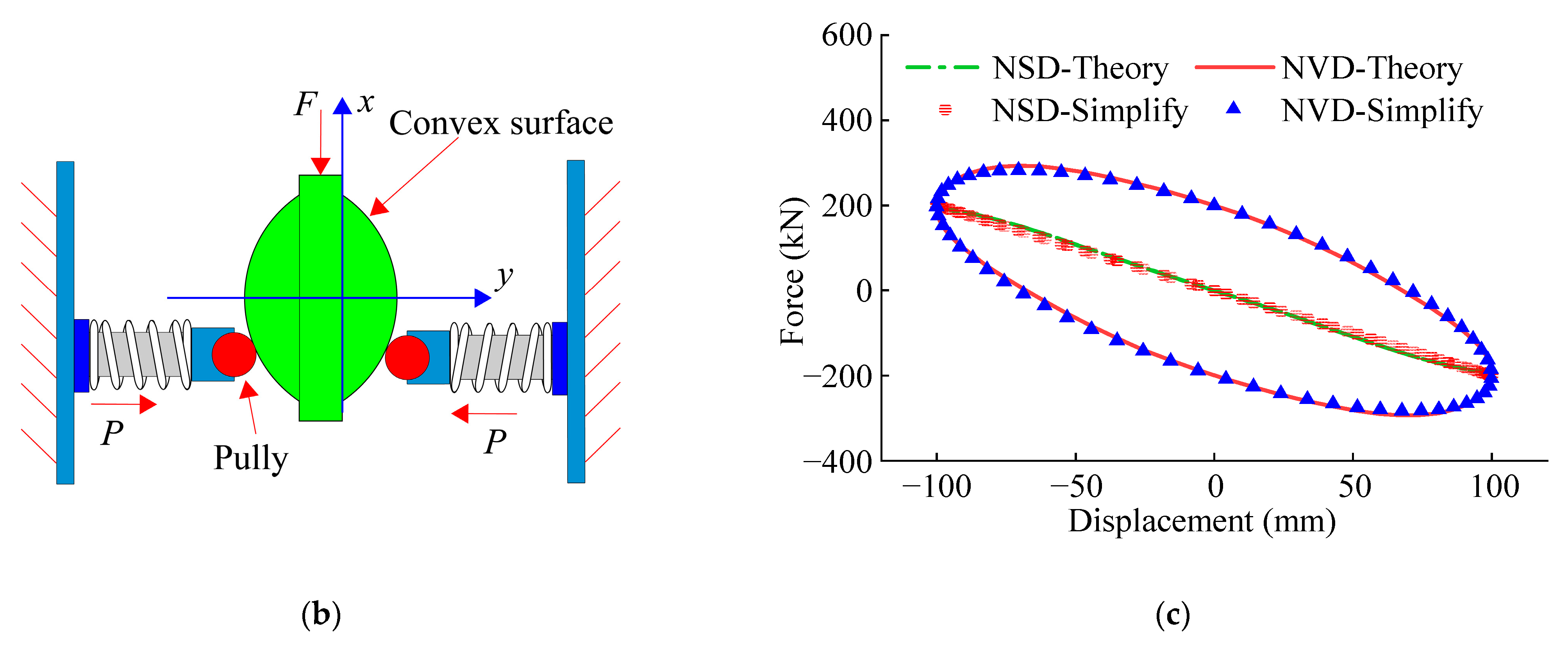
Figure 1 illustrates the negative stiffness device’s composition, the CLNVD’s structure form, and the hysteresis curve. In the multi-story structure, CLNVD is installed between the upper beam and the lower beam, which is shown in Figure 1a. The intermediate column’s position can be selected as per the building space. Hence, CLNVD can be flexibly arranged in the span. The viscous damper (VD) and negative stiffness device (NSD) are linked in parallel to constitute an NVD.
When the inter-story deformation occurs, the beam drives the intermediate column to move, and the intermediate column moves the upper node of the lever arm through the connecting rod. The lever arm rotates through the node of the lever, causing significant deformation of the viscous damper and negative stiffness device. Due to the preloading effect of the internal spring, the deformation of NSD further increases, thereby increasing the deformation of VD. When the structure undergoes inter-story deformation, the node connecting the upper intermediate column and beam will rotate, causing the intermediate column to rotate. This means that the lower node of the upper intermediate column has undergone a rotational displacement, which is different from the structural inter-story deformation. When the intermediate column is located in the middle of the span, this rotational displacement is greater than the inter-story deformation of the structure. The lever arm causes significant deformation of NVD by rotating the node. When NSD deforms, the preload of the preload spring is released and acts on the piston rod of NSD through the convex surface, with the direction of this force being the same as the direction of the piston rod’s movement. Therefore, when the NSD moves, the preloading spring will increase the displacement of the NSD. The viscous damper undergoes significant deformation under the combined action of the lever, lower intermediate column, and NSD, thereby resulting in significant energy dissipation to significantly control the seismic response of the structure.
In Figure 1b, the convex surface shape of the piston rod is f(x); the stiffness and displacement of the preloaded spring are kSP and △SP, respectively; the number of springs is N. Because the friction generated by the pulley rolling on the convex surface is much smaller than the viscous force generated by the viscous element VD, and in order to simplify the analysis, the friction force is ignored in this paper. The NSD’s negative stiffness force f(x) is calculated through Equation (1). The specific derivation process can be found in reference [52].
F ( x ) = N f ( x ) [ 1 + f ( x ) ] 2 k S P [ Δ S P + f ( x ) f ( 0 ) ]
When NVD generates sinusoidal deformation, NVD and NSD’s hysteresis curves are presented in Figure 1c. This sinusoidal deformation has an amplitude of 100 mm and a circular frequency of 1 rad/s. The spring stiffness is 1.2 kN/mm, and the preload displacement is 60 mm; the shape of the convex surface is f(x) = 50cos(2π/600x) − 7cos(2π/300x); the VD’s damping coefficient c = 2 kN/(mm/s). In NSD, there are a total of 12 preload springs acting on the convex surface. The simplified curve in Figure 1c represents the hysteresis curve with a negative stiffness of −2 kN/mm and a damping coefficient of c = 2 kN/(mm/s). According to Figure 1c, the simplified curve is in good accordance with the theoretical curve. Therefore, NVD can be composed of linear negative stiffness elements and viscous elements in parallel.

2.2. The CLNVD’s Displacement Amplification Coefficient and Energy Dissipation Coefficient

In Figure 1a, the structural damping is Rayleigh damping. The mass proportional damping of the i-th floor is Cmi, and the stiffness proportional damping is Cki. The constitutive relationship of NVD formed by VD and NSD in parallel is F = c sgn ( u ˙ d ) u ˙ d α + k N u d , where c, α, and kN are damping coefficients, damping index, and negative stiffness, respectively. u d and u ˙ d are VD’s deformation and velocity, respectively. Under earthquake action, the maximum displacement and velocity between the i-th floor of the structure are U i and U ˙ i , respectively; VD’s maximum displacement on the i-th floor is u d o . When U i is kept constant and c = 0 and kN = 0, the VD’s displacement is u a o . We can define it as follows:
γ i = u a o / U i ,   η d i = u d o / u a o
γ i is referred to as the geometric amplification coefficient in this paper. η d i represents the effect of the equivalent stiffness of the intermediate column–lever on the VD’s displacement. In this paper, it is called effective displacement factor.
The displacement amplification coefficient f d i of CLNVD is defined as the ratio of VD displacement u d o on the i-th story to the inter-story displacement U i , which is illustrated in Equation (3). The energy dissipation coefficient f E i of CLNVD is defined as the ratio of the maximum energy dissipation of VD on the i-th floor in a single cycle to the largest energy dissipation of the structural stiffness proportional damping in a single cycle, which is shown in Equation (4).
f d i = u d o U i = γ i η d i
f E i = λ c u d o u ˙ d o α π C k i U i U ˙ i = λ c f d i 1 + α U ˙ i α 1 π C k i
where the value of λ is referenced in the Chinese Code [50].
The amplification ability of CLNVD is related to coefficient γ i and coefficient η d i . f d i describes the displacement amplification capability of the CLNVD, and f E i describes the energy consumption capacity of the CLNVD. Therefore, f d i and f E i can be applied to describe the comprehensive performance of CLNVD.

2.2.1. The CLNVD’s Geometric Amplification Coefficient

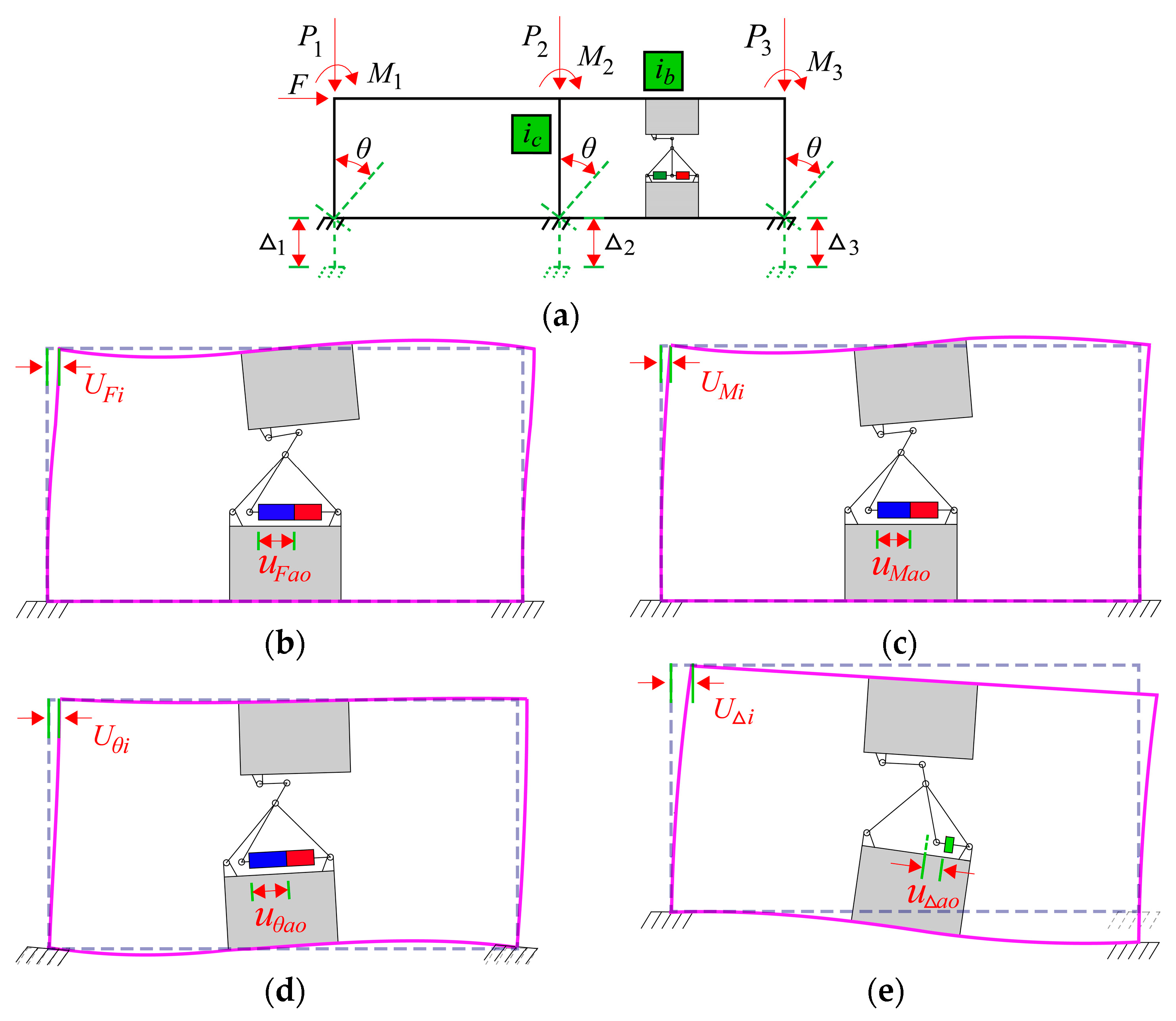
The force analysis of the i-th story in the structure shown in Figure 1a is conducted (See Figure 2a). F is the horizontal force of the i-th story; P1P3 is the column axial force of the i + 1st story; M1M3 is the bending moment at the column bottom on the i + 1st story; △1 − △3 is the cumulative axial deformation of the column from the first story to the i − 1th story; and θ is the corner angle at the column bottom on the i-th story. U i is the inter-story displacement on the i-th story. u a o is the displacement of VD on the i-th story when c = 0 and kN = 0. The isolation body illustrated in Figure 2a has the following relationship:
U i = U F i + U M i + U Δ i + U θ i
u a o = u F a o + u M a o + u θ a o + u Δ a o
In Equations (5) and (6), U F i , U M i , U Δ i , and U θ i are the inter-story displacements under the action of F, M, △, and θ, respectively. u F a o , u M a o , u Δ a o , and u θ a o are displacements of VD under the action of F, M, △, and θ, which is shown from Figure 2b–e. They are defined as follows:
ρ = i b / i c , β = a   / l , χ = l 2 / l   1
γ F = u F a o / U F i   , γ M = u M a o / U M i   , γ θ = u θ a o / U θ i   , γ Δ = u Δ a o / U Δ i
In Equations (7) and (8), as shown in Figure 1, a is the distance between the intermediate column and the left column. l is the span length, and h is the floor height. l1 and l2 are the lengths of the lever arm at the upper and lower ends; ib and ic are the beam and column’s bending line stiffness, respectively. β represents the intermediate column’s position, ρ represents the stiffness ratio of the beam to column, and χ represents the lever’s amplification coefficient.
The coefficients in Equation (8) are analyzed. γ F , γ M , γ θ , and γ Δ is expressed as follows:
γ F = χ 3 χ 6 ( β 2 β ) + 1 / 2 ( 3 ρ + 2 ) γ M = γ θ = 6 χ ( β β 2 ) γ Δ = χ ( 6 + 2 / ρ ) ( β 2 β )
Equation (9) can be found in reference [15]. And the derivation of γ F can be found in Appendix A. By combining Equations (2), (5), (6), and (8), we obtain the geometric amplification coefficient as follows:
γ i = u a o U i = γ F U F i + γ M U M i + γ θ U θ i + γ Δ U Δ i U F i + U M i + U θ i + U Δ i
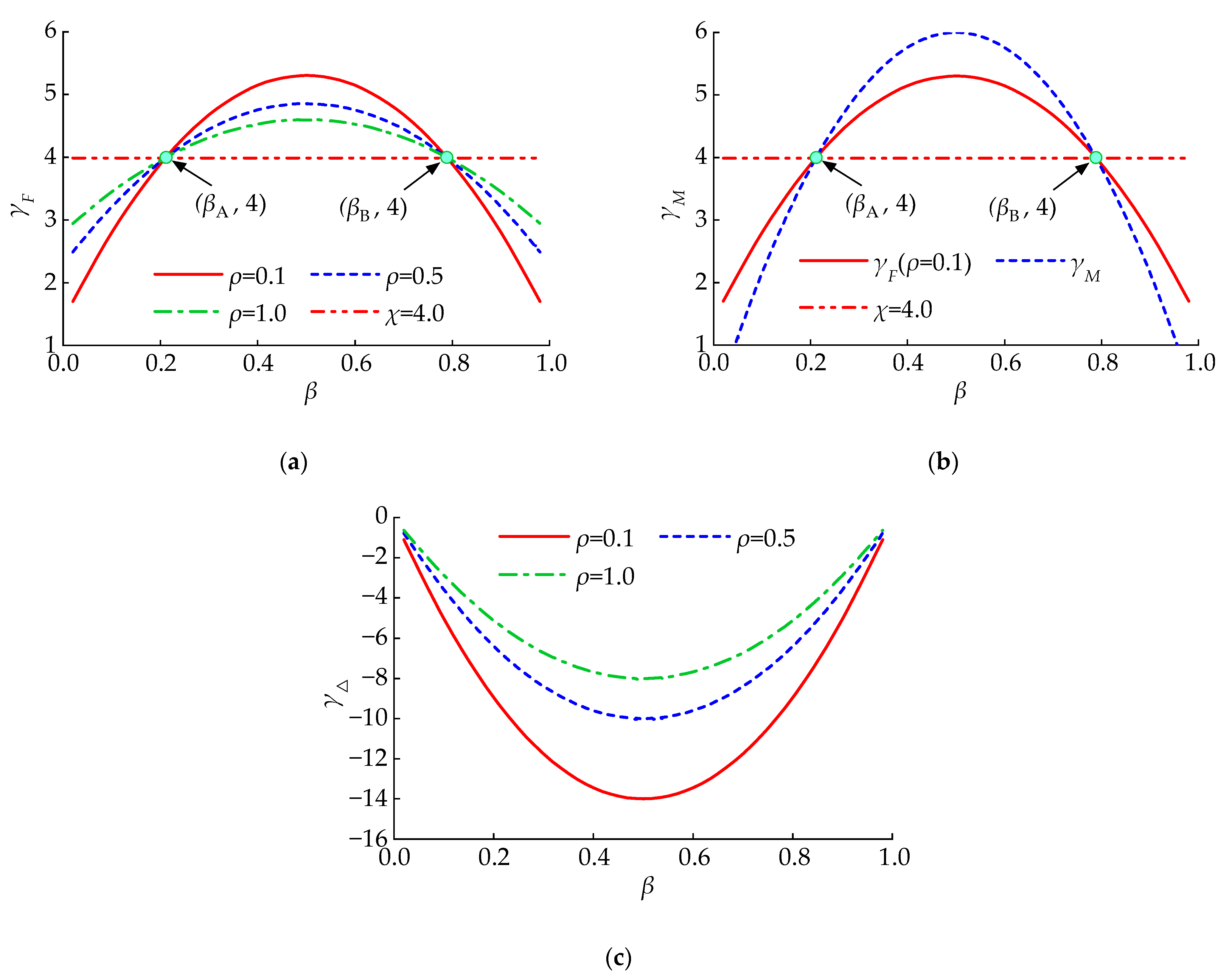
According to Equation (10), γ i is related to γ F , γ M , γ θ , and γ Δ . Figure 3 reveals the variation pattern of γ F γ M γ θ , and γ Δ with ρ and β when χ = 4. As β increases, γ F increases at first, and then decreases, reaching its maximum value when β = 0.5. There are two commonalities in γ F under different ρ. β A = 1 / 2 1 / 12 , β B = 1 / 2 + 1 / 12 . When β A < β < β B , γ F decreases as ρ increases. As is shown in Figure 3b, we can see that just like the γ F , γ M also reaches its maximum value when β = 0.5. From Figure 3c, it can be seen that when β ( 0 , 1 ) , γ Δ decreases as ρ decreases, and all values are negative. Therefore, the cumulative axial deformation of the column reduces the geometric amplification coefficient γ i . Combining Figure 3a–c, we can see that when β = 0.5, γ F and γ M obtain the positive maximum value, and γ Δ obtains the negative maximum value. For frame structures, due to the fact that the proportion of U Δ i is very small in U i , it is recommended that CLNVD lies at the middle of the span to obtain a larger geometric amplification coefficient.

2.2.2. The CLNVD’s Effective Displacement Factor

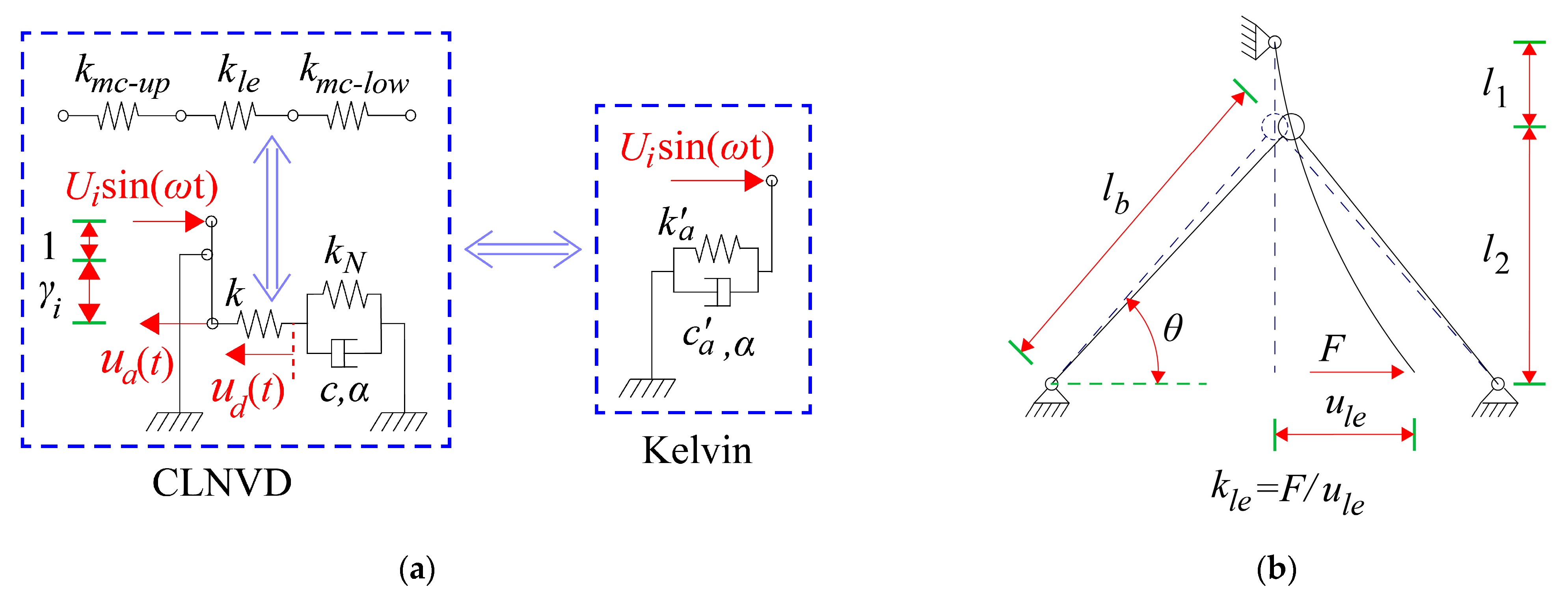
The derivation of the effective displacement factor η d i requires transforming the CLNVD’s simplified mechanical model into the Kelvin model, which is displayed in Figure 4a. k is the equivalent stiffness of the lower intermediate column, the upper intermediate column, and the lever in series, which is calculated by Equation (11). In Equation (11), k l e is calculated by Equation (12), and k m c u p is calculated by Equation (13). Equation (11) can refer to reference [18]. k l e is the stiffness of the lever amplification device, which is illustrated in Figure 4b. k m c u p is the stiffness of the upper middle column after it is connected with the lever (See Figure 4c). k m c l o w is the stiffness of the lower middle column after it is connected with the lever (See Figure 4d). i m c and i v m c are the intermediate column’s flexural line stiffness and shear line stiffness, respectively. i l e is the lever arm’s bending line stiffness; l b is the brace length; A b is the brace’s cross-sectional area; and θ is the brace’s horizontal included angle.
k = k l e k m c u p 2 k l e + k m c u p
k l e = 1 ( l 1 + l 2 ) 2 χ 2 3 i l e ( χ + 1 ) 2 + ( χ + 1 ) 2 l b 2 E A b cos 2 θ
k m c u p = 1 χ 2 [ β f 1 + ( 1 β ) f 2 ] h 2 2 f 3 i b + χ 2 ( 12 i m c + i v m c h 2 ) 12 i m c i v m c
In Equation (5), f 1 = ( 1 + β ρ ) [ β ( 2 3 β ) 2 ( 1 + 1 ρ ) ( 1 β ) ( 3 β 1 ) ] , f 2 = [ 1 + ( 1 β ) / ρ ] [ ( 1 β ) ( 3 β 1 ) 2 β ( 1 + 1 / ρ ) ( 2 3 β ) ] , f 3 = 2 8 ( 1 + 1 / ρ ) 2 .
In order to achieve the transformation between the mechanical model of CLNVD and the Kelvin model, equal force, equal deformation, and equal energy dissipation are utilized here. The Kelvin model’s damping coefficient is c a , and the spring stiffness is k a , which is shown in Figure 4a. Assuming the sinusoidal deformation generated by CLNVD, according to the definition of u a o , we obtain u a o = γ i U i . According to equal force and equal deformation, u d ( t ) , u ˙ d ( t ) , and F ( t ) of VD are revealed as follows:
u d ( t ) = u a o sin ( ω t ) k a u a o sin ( ω t ) + c a ω u a o cos ( ω t ) / ( γ i 2 k )   u ˙ d ( t ) = ω u a o cos ( ω t ) k a ω u a o cos ( ω t ) c a ω 2 u a o sin ( ω t ) / ( γ i 2 k ) F ( t ) = c u ˙ d ( t ) + k N u d ( t ) = k a u a o sin ( ω t ) + c a ω u a o cos ( ω t ) / γ i 2
Equation (14) is utilized to solve the stiffness k a and damping coefficients c a in the Kelvin model. Details are as follows:
k a = γ i 2 k ( k N / k ) 2 + k N / k + ( c ω / k ) 2 / ( 1 + k N / k ) 2 + ( c ω / k ) 2 c a = γ i 2 c / ( 1 + k N / k ) 2 + ( c ω / k ) 2
The loss stiffness of VD is defined as k d = c ω . η d is solved based on equal energy consumption. Details are as follows:
η d = u d o / u a o = 1 / ( 1 + k N / k ) 2 + ( k d / k ) 2 0.5
When damping index α = 0 , k d = c / u d o , k a = γ i 2 k ( k N / k + k d / k ) / ( 1 + k N / k + k d / k ) , c a = f d   c , and η d = 1 / ( 1 + k N / k + k d / k ) . According to the reference [53], when 0 < α 1 , k d and η d are approximately expressed by interpolation as follows:
k d = c ω α / u d o 1 α   ,   0 < α 1
η d = 1 / ( 1 + k N / k ) 1 + α + ( k d / k ) 1 + α 1 0.5 α   ,   0 < α 1
When 0 < α 1 , k a is approximately expressed by interpolation. c a is Solved through Equation (18). k a and c a are as follows:
k a = γ i 2 k ( 1 + k N / k ) α k N / k + ( k d / k ) 1 + α / ( 1 + k N / k ) 1 + α + ( k d / k ) 1 + α ,   0 < α 1 c a = ( γ i η d ) 1 + α c ,   0 < α 1
Figure 5 reveals the variation in the η d and the k a / ( γ i 2 k ) with k d / k . As k d / k increases, η d decreases while k a / ( γ i 2 k ) increases. In comparison with the traditional viscous dampers, NVD’s η d is improved due to the negative stiffness effect, while the degree of improvement weakens as k d / k increases. Meanwhile, when k d / k is smaller, k a / ( γ i 2 k ) < 0 . Therefore, the CLNVD provides a negative stiffness to the structure. On the one hand, the negative stiffness property of the CLNVD reduces the shear force demand of the structure; on the other hand, it raises the displacement demand. However, higher η d of NVD will suppress the displacement demand of the structure.

3. Parameter Analysis and Optimization Design

The coefficients f d and f E of CLNVD are jointly affected by the intermediate column’s position β , the lever’s amplification factor χ , the bending line stiffness i b of the beam, negative stiffness k N , and damping coefficient c . For the convenience of parameter analysis, the single-story structure shown in Figure 6 is taken as the analysis object.
For single-story structures, γ M = γ θ = γ Δ = 0 . Combining Equations (2)–(4), (9), (10), and (18), we obtain the following:
f d = χ 3 χ 6 ( β 2 β ) + 1 / 2 ( 3 ρ + 2 ) ( 1 + k N / k ) 1 + α + ( k d / k ) 1 + α 1 0.5 α
f E = λ c f d 1 + α ( ω U 1 ) α 1 π C k 1
where k is calculated by Equation (11), and k d is calculated by Equation (17); U 1 is the inter-story displacement, and C k 1 is the structural stiffness proportional damping coefficient. For ω , we take the first modal frequency of the structure.
When the damping index α < 1 , Equation (17) cannot be directly employed since u d o is unknown. However, the following iterative method is applied. This iterative method is as follows:
(1)
The damper displacement u d o is assumed to be equal to the inter-story displacement U 1 .
(2)
u d o is substituted into Equation (17) for calculation, and Equations (20) and (21) are utilized to calculate f d and f E .
(3)
The error ε = u d o / ( f d U 1 ) 1 is calculated. When ε > 1 % , u d o is made to be equal to f d U 1 , and steps from 2 to 3 are repeated. When ε < 1 % , the iteration ends.
For the convenience of discussion, an analysis is conducted on the single-story structure illustrated in Table 1. The material of the lever amplification device is Q235, and the concrete material grade of the structure is C35. The cross-section of the lever box is 230 × 140 × 25 × 25 (unit: mm), with the length of 1000 mm; the box section of slant support is 200 × 200 × 25 × 25 (unit: mm). The structure maintains elasticity, and the modal frequency is ω = 8.1   rad / s ; the structure’s stiffness proportional damping is C k 1 = 1.56   kN / ( mm / s ) , and the inter-story displacement under the circumstance of fortification earthquakes is U 1 = h / 400 . The method adopted for parameter analysis in this section is to keep other parameters unchanged and observe the impact of changing a certain parameter on the efficiency of CLNVD.

3.1. Parameter Analysis

3.1.1. Impact of the Intermediate Column’s Position and Its Bending Line Stiffness

The intermediate column’s position β affects CLNVD’s f d and f E . Figure 7 reveals the curves of γ , η d , f d , and f E with β . As is described in Figure 7a, when the intermediate column moves from the ends of the span to the middle of the span, γ increases, while η d increases at first and decreases subsequently. However, the increase in γ is even greater. Therefore, when β = 0.5 , f d and f E reach its maximum value. SAP2000 (Version 23.1.0) is used for numerical simulation, and seven seismic waves from Section 4.2 are selected. The analysis results of f d in this section are taken as the average of the seven seismic wave calculation results. The results indicate that the theoretical calculation results of f d are highly consistent with the numerical simulation results. In Figure 7b, i m c 1 refers to the intermediate column’s bending stiffness with the cross-section of 1600 mm × 250 mm. As is displayed in Figure 7b, f d and f E rapidly increase at first, and then slowly decrease with the increase in i m c . A larger cross-section of the intermediate column is not conducive for CLNVD to obtain the peak value of f d and f E . In order to ensure that CLNVD has good energy consumption capacity, the CLVD is required to lie at the middle span under the condition that the building space allows this.

3.1.2. Impact of Beam’s Bending Line Stiffness

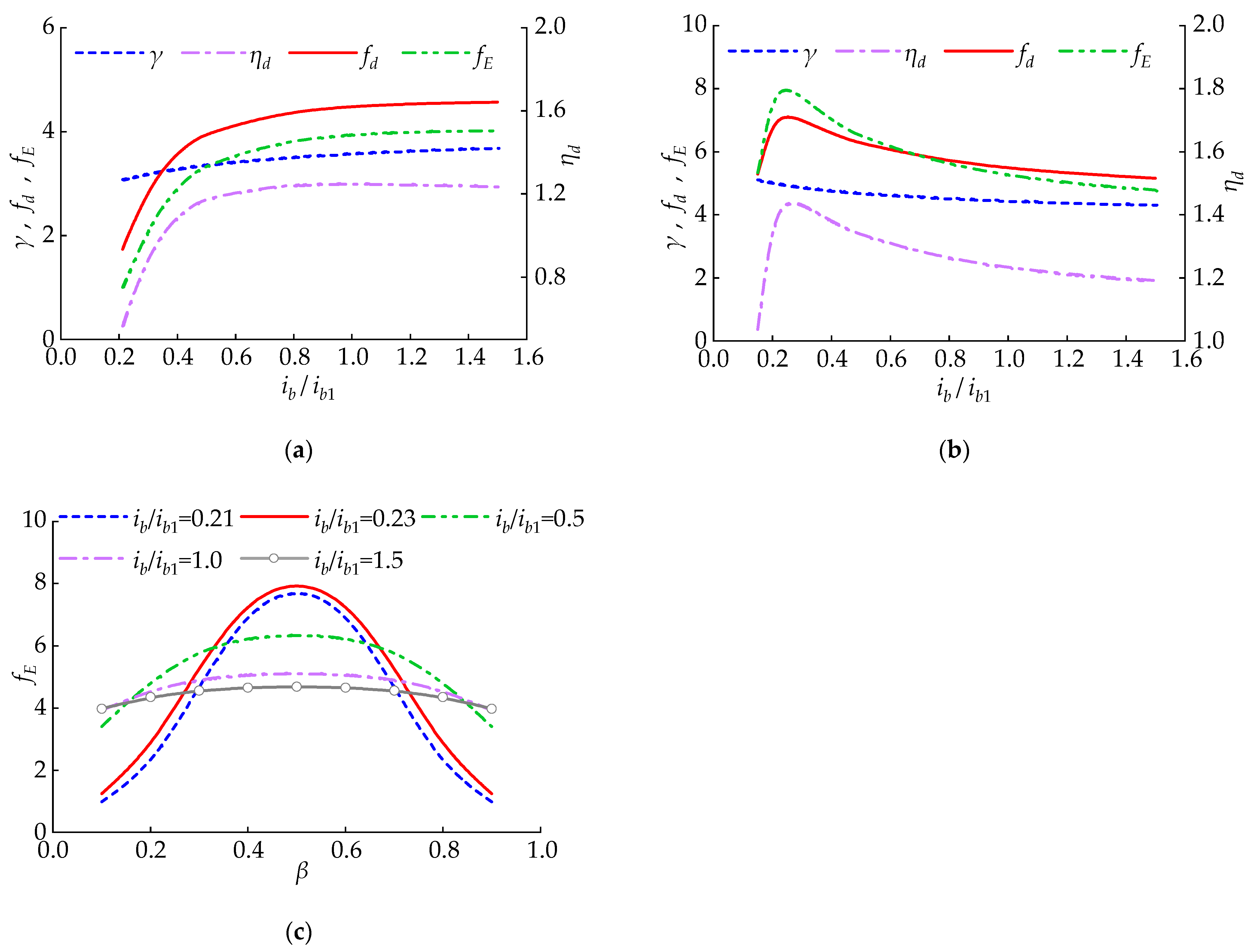
This section expounds the law of f E and f d as the beam’s bending line stiffness changes. In Figure 8, i b 1 refers to the beam’s bending stiffness with the cross-section of 400 mm × 800 mm. When the intermediate column’s position β changes, f d and f E do not change in the same way with i b . As is shown in Figure 8a, when β = 0.1 , γ and η d increase with the increase in i b . Hence, f d and f E increase as i b increases. As is revealed in Figure 8b, when β = 0.5 , with the increase in i b , γ slowly decreases, and η d first increases and then decreases. Therefore, as i b increases, f d and f E first rapidly increase and then decrease. For different β , the impact law of i b on f E is shown in Figure 8c. From Figure 8a–c, it is concluded that CLNVD located at the mid span can achieve higher f E with a smaller beam cross-section.

3.1.3. Impact of Lever’s Bending Line Stiffness and Leverage Amplification Coefficient

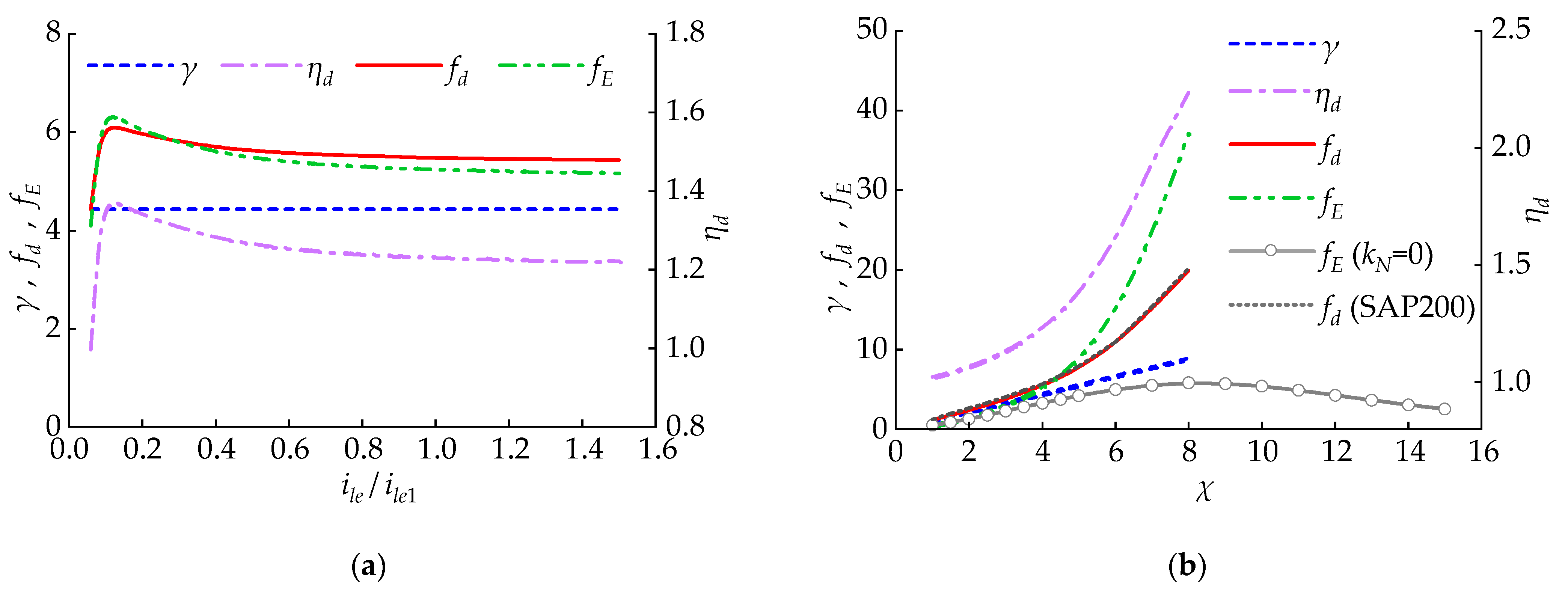
This section expounds the variation in f d and f E with the lever’s bending line stiffness i l e as well as the lever’s amplification coefficient χ . In Figure 9, i l e 1 refers to the bending line stiffness with the box section of 230 × 140 × 25 × 25 (unit: mm). The impact of the stiffness and amplification coefficient is not the same. As is shown in Figure 9a, like i m c , f d and f E rapidly increase at first and then decrease slowly with the increase in i l e . As is shown in Figure 9b, when k N = 0 , there exists an optimal leverage amplification coefficient χ which enables f E  to reach the maximum. When k N 0 , f d and f E increase with the increase in the lever’s amplification coefficient χ . However, this does not mean that larger options can be selected without limitations. The larger χ causes the lever and beam to bear a greater force, which requires a larger cross-section to maintain elasticity. SAP2000 (Version 23.1.0) is used for numerical simulation. The results indicate that the theoretical calculation results and numerical simulation results of f d are very consistent under different χ conditions.

3.1.4. Impact of the Damping Coefficient and Damping Exponent

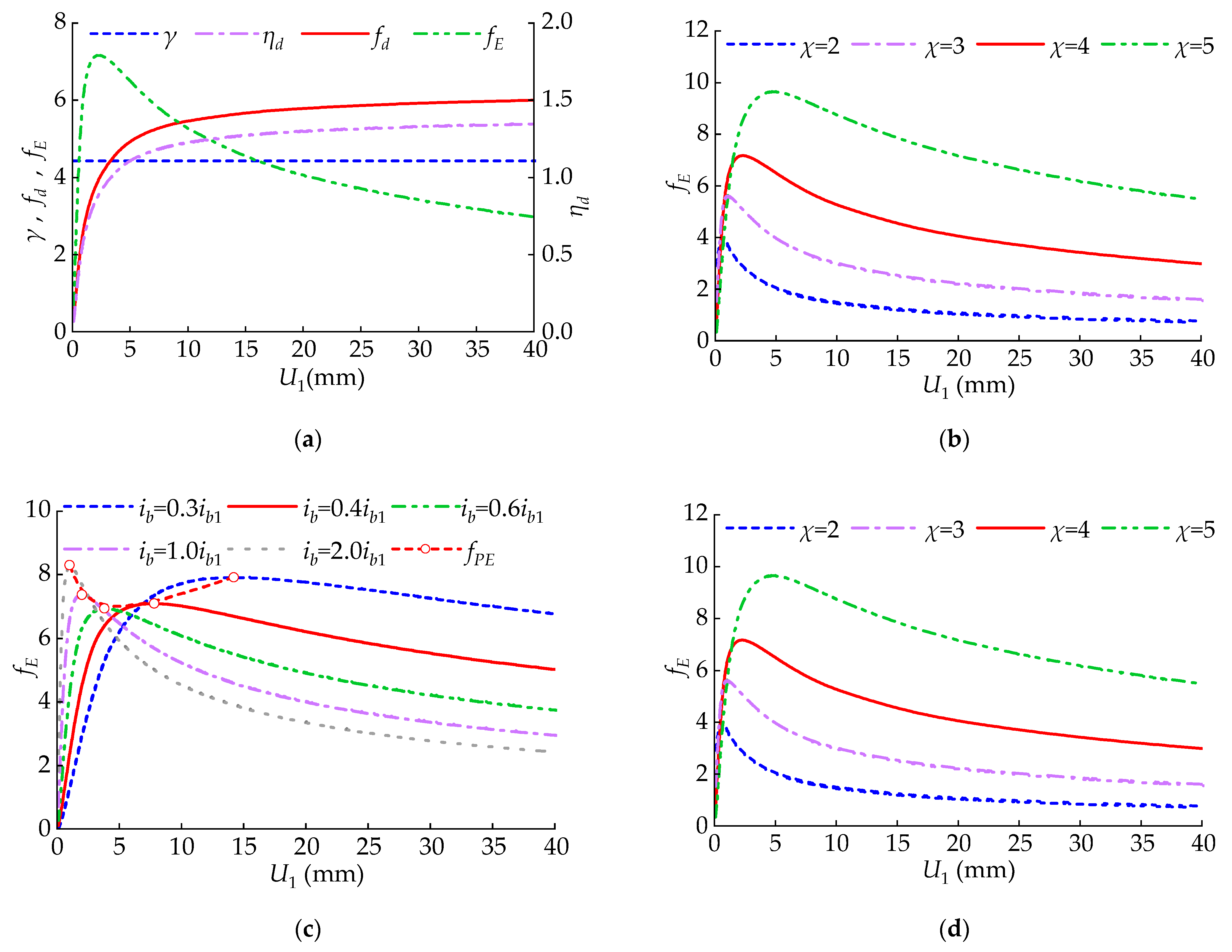
This section expounds the variation law of f d and f E with the damping index α as well as the damping coefficient c . From Figure 10a,b, we obtained a conclusion that η d gradually decreases when increasing the damping coefficient c or index α . Therefore, f d gradually decreases, while f E first increases and then reduces. Therefore, it is necessary to select appropriate index α and damping coefficient c to enable f E to reach the largest value. Under different exponent α , the variation law of f E with the change in the damping coefficient c is shown in Figure 10c. f P E in Figure 10c refers to the peak value of the energy dissipation coefficient f E . Figure 10d presents the curve of k d / k and η d corresponding to f P E in Figure 1c with the index α . According to Figure 10d, it is indicated that f E reaches the maximum value when the c and α make k d / k = 1 + k N / k or η d = 1 / [ 2 ( 1 + k N / k ) 1 + α ] 1 0.5 α .

3.1.5. Impact of NSD’s Negative Stiffness

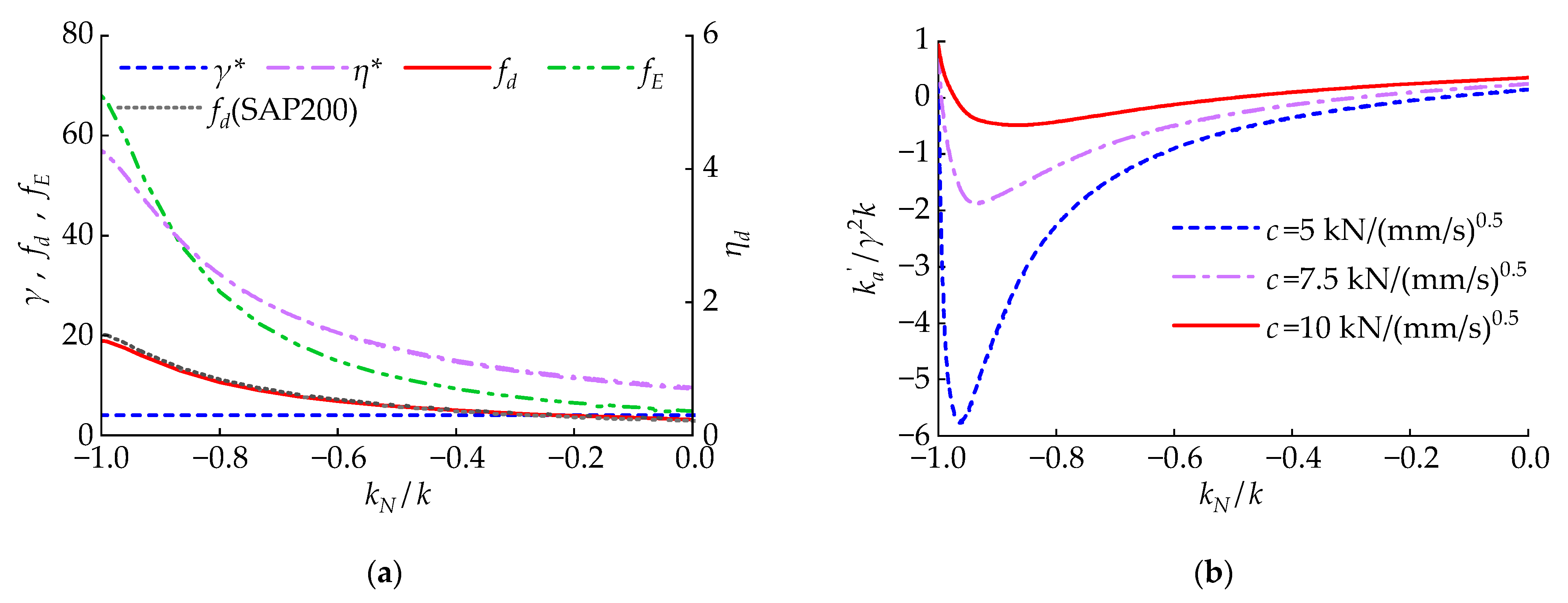
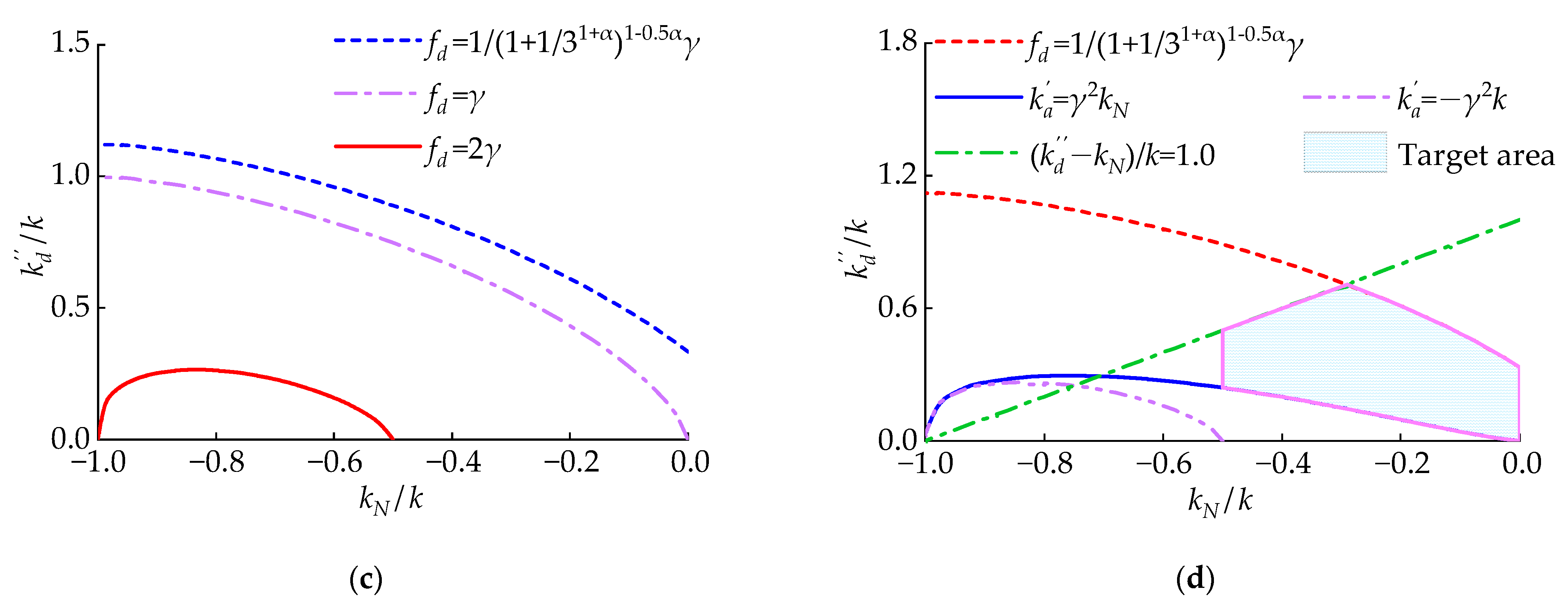
This section analyzes the variation in f d and f E with the changes in NSD’s k N . As is shown in Figure 11a, when k N  decreases, η d  gradually increases. Therefore, f d  and f E  gradually increase. From Figure 11b, it is concluded that when k N  decreases, k a  decreases at first and then increases. Moreover, a smaller c  will give CLNVD larger negative stiffness. Therefore, the size of k N  should be controlled to make CLNVD achieve a higher f d while avoiding an influential decrease in the structure’s overall stiffness. SAP2000 (Version 23.1.0) is used for numerical simulation. The results indicate that the theoretical calculation results and numerical simulation results of f d are very consistent under different k N conditions. The CLNVD can be guaranteed to achieve a high f d  by controlling the size association between k N / k and k d / k . The reference [54] requires that the ratio of the viscous damper’s loss stiffness to the brace stiffness is less than 1/3. When f d = 1 / ( 1 + 1 / 3 1 + α ) 1 0.5 α γ , f d = γ , and f d = 2 γ , the size relationship between k N / k and k d / k can be calculated from Equation (22) as follows:
k N / k = 1 + 1 / 3 1 + α ( k d / k ) 1 + α 1 / ( 1 + α ) 1 , f d = 1 / ( 1 + 1 / 3 1 + α ) 1 0.5 α γ k N / k = 1 ( k d / k ) 1 + α 1 / ( 1 + α ) 1 , f d = γ k N / k = ( 1 / 2 ) 1 / ( 1 0.5 α ) ( k d / k ) 1 + α 1 / ( 1 + α ) 1 , f d = 2 γ
The size of CLNVD’s k a can also be controlled by controlling the size association between k N / k and k d / k . When k a = γ 2 k N or k a = γ 2 k , the size association between k N / k and k d / k are showed in Equation (23).
( 1 + k N / k ) α ( k N / k ) 2 / ( 1 k N / k ) = ( k d / k ) 1 + α ,   k a = γ 2 k N ( 1 + k N / k ) α ( 1 + 2 k N / k ) = 2 ( k d / k ) 1 + α ,   k a = γ 2 k
Combining Equation (22) as well as Figure 11c, we can see that when k N / k 1 + 1 / 3 1 + α ( k d / k ) 1 + α 1 / ( 1 + α ) 1 , f d 1 / ( 1 + 1 / 3 1 + α ) 1 0.5 α γ . Combining Equation (23) and Figure 11d, we can see that when ( 1 + k N / k ) α ( k N / k ) 2 / ( 1 k N / k ) ( k d / k ) 1 + α , k a γ 2 k N . When ( 1 + k N / k ) α ( 1 + 2 k N / k ) 2 ( k d / k ) 1 + α , k a γ 2 k . Through Equation (19), it can be obtained that when k N / k 0.5 , k a γ 2 k . We can see from Section 3.1.4 that when k d k N / k 1 , f E increases as the damping coefficient c increases. Thus, according to the above analysis, it is recommended that the target area in Figure 11d should be taken as the range of values for k N / k and k d / k . Within this target area, we can see the following: f d 1 / ( 1 + 1 / 3 1 + α ) 1 0.5 α γ ; γ 2 k N k a ; f E rises when increasing the damping coefficient c .

3.1.6. Impact of Inter-Story Displacement

This section explores the variation law of f d and f E with the inter-story displacement U 1 . U 1 affects f d and f E by means of changing the loss stiffness k d of VD. As is shown in Figure 12a, when increasing U 1 , f d gradually increases, and f E increases first and later decreases. Increasing the lever’s amplification coefficient χ can increase f E , which has been discussed in Section 3.1.3. As is shown in Figure 12b, when U 1 is larger, increasing χ has a significant improvement on f E . However, when U 1 is small, increasing χ does not have a good effect on improving f E . In Figure 12c, i b 1 refers to the beam’s bending line stiffness with the section of 400 mm × 800 mm. As is shown in Figure 12c, when U 1 is small, increasing i b has a significant improvement on f E . However, when U 1 is larger, increasing i b will lead to a decrease in f E . Meanwhile, increasing i b causes the peak energy-consumption efficiency f P E to decrease first and then increase. In Figure 12d, c 1 = 5 ( kN / ( mm / s ) 0.5 ) . As is revealed in Figure 12d, when U 1 is larger, increasing the damping coefficient c has a significant improvement on f E . However, when U 1 is smaller, a higher damping coefficient c leads to a decrease in f E . Meanwhile, increasing the coefficient c does not change the magnitude of the peak energy consumption coefficient f P E . Moreover, it will cause f P E to move towards larger displacements.

3.2. CLNVD’s Optimum Design

3.2.1. Optimum Strategies for the CLNVD

In order to ensure that the CLNVD has a large coefficient f d and coefficient f E under the circumstance of frequent earthquakes (or fortification earthquakes), on the basis of the analysis in Section 3.1, the following steps are adopted to optimize the CLNVD:
(1)
The position of the intermediate column β = 0.5 is selected, as well as the beam section and lever amplification factor χ ; the line stiffness ratio ρ of beam to column is calculated. According to Equations (9) and (10), the geometric amplification coefficient is calculated. 1 / ( 1 + 1 / 3 1 + α ) 1 0.5 α γ is judged to estimate whether it is higher in comparison with the pre-set target of f d . If it is not higher, the following methods are applied: to increase χ , or to decrease ρ .
(2)
CLNVD’s parameters (such as intermediate column section, lever section, negative stiffness, damping coefficient, and damping index) are selected so that the values of k d / k and k N / k are within the target area (See Figure 11d). The inter-story displacement target value and the iterative method in Section 3.1 can be used to calculate k d ; the η d is calculated through Equation (18).
(3)
γ and η d are substituted into Equation (3) to calculate the displacement amplification coefficient f d , and Equation (4) is utilized to calculate the energy dissipation coefficient f E .
(4)
f E is judged if the predetermined goals are met. If not, the following methods are applied for optimization: to enhance the stiffness i b and damping coefficient c ; to enhance the stiffness i b and the lever’s coefficient χ ; to increase the lever’s coefficient χ and reduce the damping coefficient c ; or to reduce the NSD’s negative stiffness k N . It is necessary to verify again if k N / k and k d / k are within the region proposed in Section 3.1.5, and Step (3) and Step (4) should be repeated. If f E cannot meet the set target when k d / k is on the upper limit of the target region in Figure 11d, we should increase the beam section and return to Step (3).

3.2.2. Optimum Design for Structures with the CLNVD

With the aim to evaluate the damping contribution of dampers to the overall structure and control the structure‘s deformation, the current vibration-reduction design methods mostly utilize additional damping ratios as well as the maximum inter-story displacement angle as control objectives. For additional CLNVD structures, this paper proposes a seismic design method with coefficient f d , coefficient f E , maximum inter-story displacement angle, and additional damping ratio as control objectives. In contrast to the structure without the CLNVD, the stiffness and damping properties of the multi-story structures with the CLNVD vary greatly, and such changes are difficult to predict before the actual calculation. Therefore, for the vibration-reduction design of the additional multi-story CLNVD structures, the current design method is to conduct trial calculations, while ensuring that CLNVD has a high energy consumption, until the proposed design goals are met. During the trial calculation process, it is necessary to utilize the optimization strategy in Section 3.2.1 to optimize CLNVD. Subsequently, the design is conducted according to the vibration-reduction design process in Section 3.2.2. Figure 13 illustrates the vibration-reduction design flowchart. The specific design steps are as follows:
(1)
The target values are set for f E , f d , maximum inter-story displacement angle, and additional damping ratio.
(2)
The stiffness ratio damping C k of the structure, the seismic response of structures without CLNVD, and the seismic response of structures with additional expected damping ratios are calculated. The floors with the CLNVD layout based on the seismic response of the structure without the CLNVD are selected, and the number of CLNVDs based on the building area (a ratio of building area to number of dampers between 100 and 200 is more reasonable) is selected. The number of CLNVDs for each floor based on the total number of CLNVDs and the layout floor is set. The parameters of CLNVD are set, and CLNVD is optimized according to Section 3.2.1.
(3)
The time history analysis is conducted under the circumstance of frequent or fortification earthquakes, and it is judged whether f d , f E , damping ratio, and displacement angle satisfy the goals. If not, we should increase the quantity of the CLNVDs or return to Step (2) for optimum strategies.
(4)
The time history analysis is conducted under the circumstance of rare earthquakes, and it is judged if the displacement angle satisfies the goals. If the goals are not satisfied, we should raise the quantity of the CLNVDs and return to Step (3).
When the viscous damper is linear, the loss stiffness of the damper does not change with the displacement of the damper, thus avoiding the usage of iterative programs. When the viscous damper is nonlinear, if no iteration is carried out, the approximate formula for the damper loss stiffness provided in the reference [53] can be used for relevant calculations, while the accuracy of the approximate formula is not ideal. The relevant parameters of CLNVD are selected in the target region in Figure 11d, which will enable CLNVD to have a large displacement amplification factor and avoid providing a large negative stiffness to the structure. Hence, for single-story structures and linear viscous dampers, relevant parameters can be directly selected in the target area of Figure 11d for ideal CLNVD design. For nonlinear viscous dampers and multi-story structures, the damping design of additional CLNVD structures needs to follow the design process in Section 3.2.2.

4. Engineering Example Analysis

4.1. Project Overview

With the aim to test CLNVD’s vibration-reduction efficiency and optimization strategy, this section takes a 9-floor concrete frame as an example to analyze. This concrete frame building has a height of 36 m and a self-weight of 9784 tons. The seismic fortification intensity is 8 degrees (0.2 g), and the site’s characteristic period is 0.45 s. The structural parameters are revealed in Table 2, and the dynamic properties are shown in Table 3. The structure utilizes Rayleigh damping, with a stiffness ratio coefficient of 2.3 × 10⁻³ and a mass ratio coefficient of 0.35. The additional CLNVD structural optimization design objective is as follows: under the circumstance of fortification earthquakes (PGA is 0.2 g), the damping ratio provided by CLNVD is 18%, and the peak inter-story displacement angle is smaller than 1/400; under rare earthquakes (PGA is 0.4 g),the peak inter-story displacement angle is smaller than 1/200, and f d > 3.5 and f E > 30 .

4.2. Scheme Design

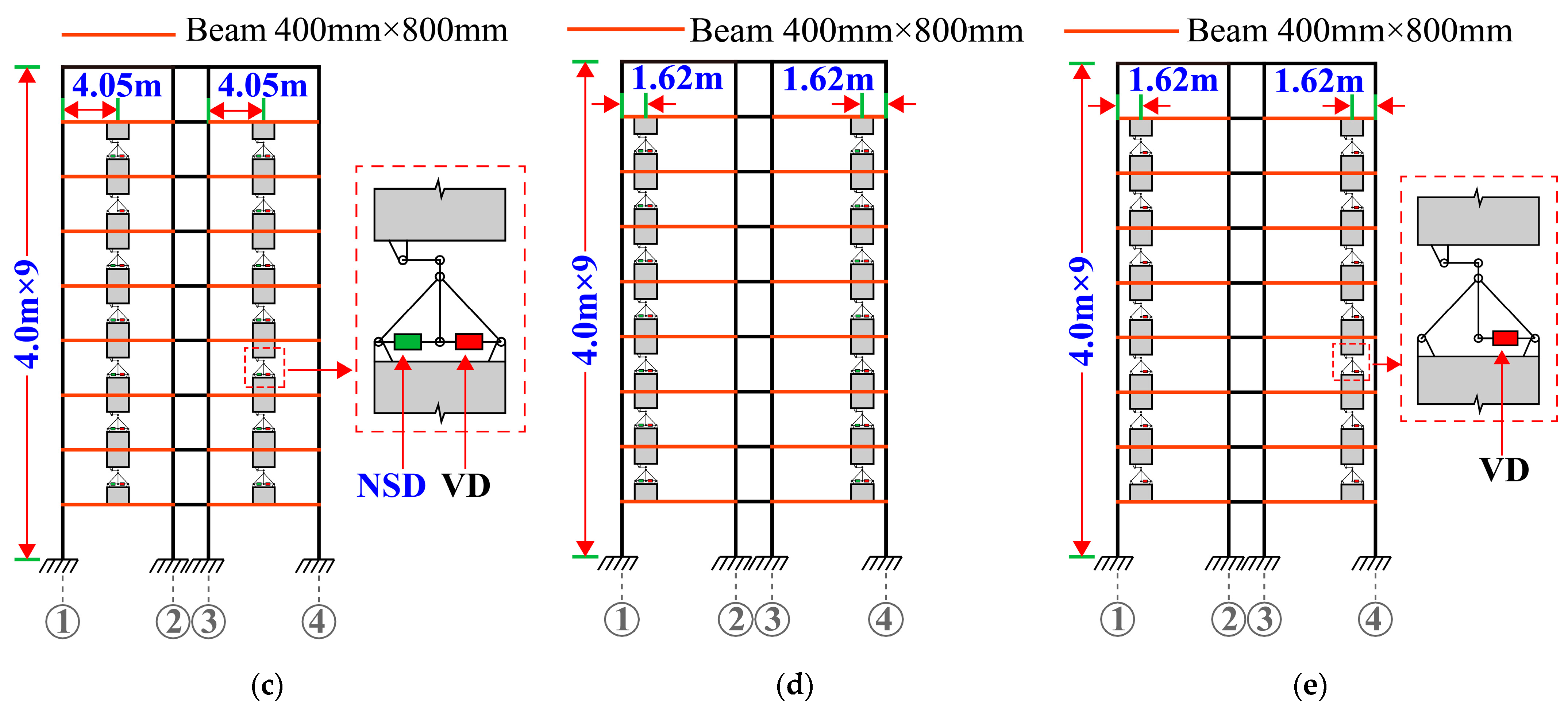
In this section, three CLNVD schemes are designed. Based on the optimization design method, Scheme 1 is obtained. In comparison with Scheme 1, the position of the CLNVD in Scheme 2 is β = 0.2 . In contrast to Scheme 2, Scheme 3 does not have the NSD. The layout of Scheme 1 to Scheme 3 in the floors is described in Figure 14. The CLNVD’s parameters for each scheme are shown in Table 4. The lever is made of Q235 steel. The box-shaped cross-sections corresponding to the support and lever arm are 300 mm × 140 mm × 20 mm × 20 mm, and 200 mm × 200 mm × 25 mm × 25 mm, respectively, with a lever arm’s length of 1000 mm.
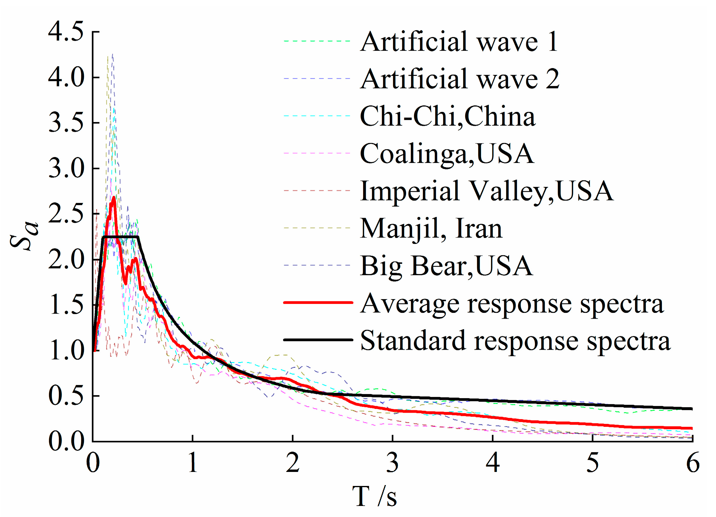
The structure’s section design with the CLNVDs is on the basis of the internal forces of the response spectrum design under the circumstance of fortification earthquakes. As per Chinese code [55], 7 seismic waves are selected, and 7 seismic waves’ response spectra are presented in Figure 15. The average of all the waves’ analysis results is taken as the relevant analysis result. As for fortification earthquakes, elastic dynamic analysis is carried out through adopting SAP2000 software (Version 23.1.0); as for rare earthquakes, elastic-plastic dynamics is implemented by means of utilizing PERFORM-3d software (Version 8.0). In elastoplastic analysis, fluid damper elements are used for VD, and a nonlinear elastic gap hook bar is used for NSD. For steel bars, a double-line model is used; for unconstrained concrete and restrained concrete, the trilinear model and Mander model are applied, respectively; for the beam and column components, a nonlinear fiber section model is adopted. Structures without CLNVD are forced to maintain elasticity. In this way, only the CLNVD’s control effect on the structure’s seismic response can be considered, and the changes caused by the structure’s plastic deformation are not taken into account additionally. Meanwhile, this section only analyzes the CLNVD’s damping effect in the structure’s north–south direction.

4.3. Vibration-Reduction Effect

Figure 16 shows f d and f E of the CLNVD under the circumstance of fortification earthquakes and rare earthquakes. From Figure 17, it can be seen as follows: Scheme 1 is the most optimal, Scheme 2 is the second optimal one, and Scheme 3 is the poorest. Meanwhile, for Scheme 1, f d > 3.5 and f E > 30 . Therefore, Scheme 1 satisfies the goals. By comparing Scheme 2 and Scheme 1, we can see that the CLNVD has the highest efficiency when the CLNVD is designed at the middle span. Through comparing Scheme 3 and Scheme 2, we can see that the CLNVD’s stiffness kN greatly increases the energy dissipation capacity of the damper.
Figure 17a reveals the NVD’s hysteresis curve of B (1–2) axis on the 5th floor under the rare earthquake’s Big Bear waves. As is shown in Figure 17a, NSD causes the hysteresis curve of NVD to become inclined, and the damper’s hysteretic curve area in scheme 1 is larger. Scheme 1 is obtained after optimizing and designing in Section 3.2. Therefore, k N / k and k d / k are located within the target region presented in Figure 11d (See Figure 17b).
The damping ratio provided by CLNVDs is determined according to the strain energy method specified in Chinese code [50]. According to Table 5, the damping ratios of Scheme 1, Scheme 2, and Scheme 3 are 20.5%, 14.2%, and 8.5%, respectively. Scheme 1 can satisfy the set goals. In addition to the additional damping ratio, the ratio of the cumulative energy dissipation of the damper to the seismic input energy can also be employed as an indicator to measure the performance of CLNVD. As per Table 6, under the circumstance of rare earthquakes, the cumulative energy ratios of dampers from Scheme 1, Scheme 2, and Scheme 3 are 77.9%, 70.8%, and 57.4%, respectively. The internal plastic cumulative damage energy ratios from Scheme 1 to Scheme 3 are 0.8%, 2.1%, and 6.1%, respectively. From this, it can be seen that all three proposed schemes in this paper can significantly reduce structural damage, while Scheme 1’s CLNVD system has the strongest energy dissipation capacity and the optimal control effect on structural damage.
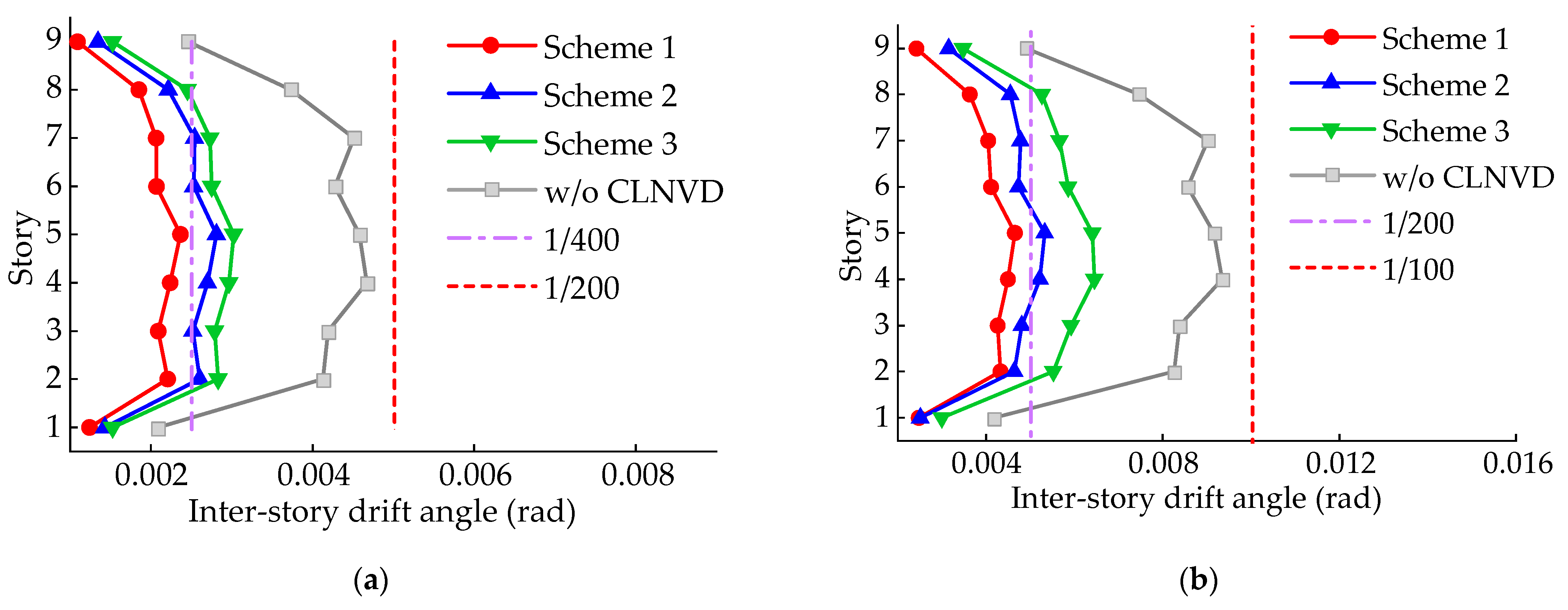
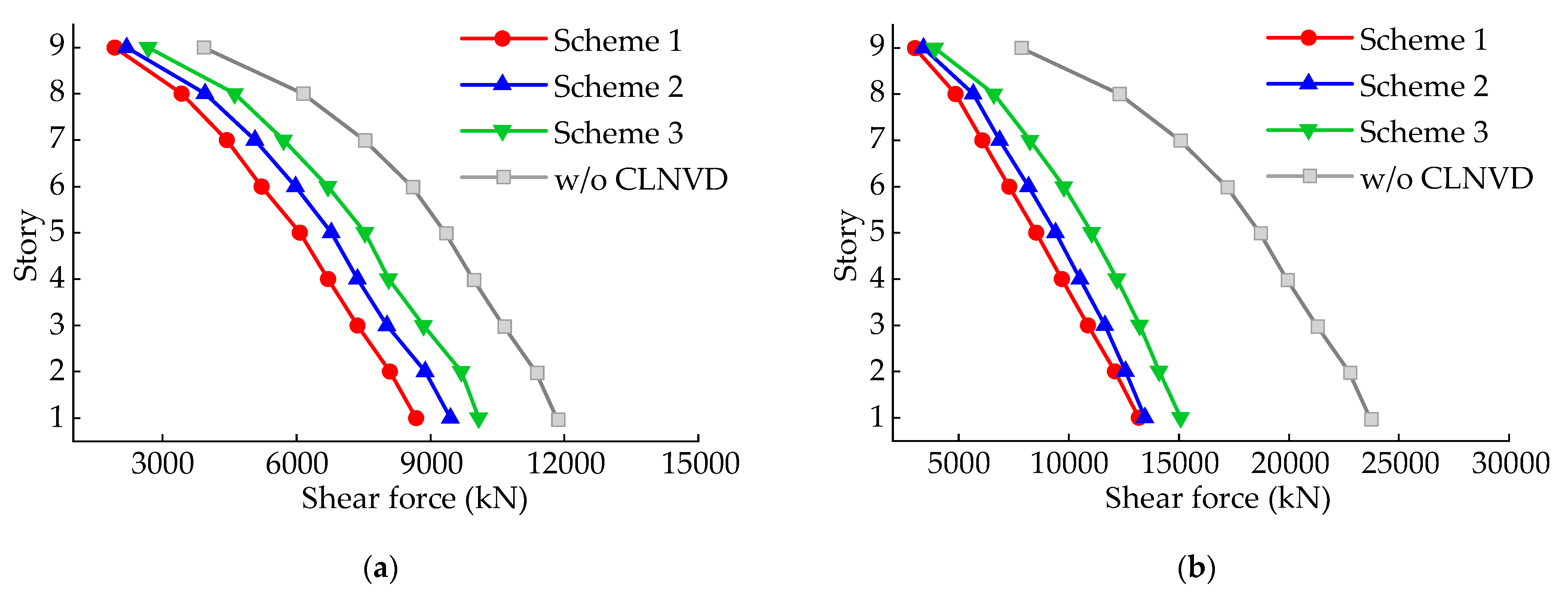
Figure 18 and Figure 19 reveal the structure’s inter-story displacement as well as story shear force under three different schemes. As shown in Figure 18, the CLNVD of Scheme 1 reduces the maximum of the structure’s inter-story displacement angle from 1/200 to 1/400 under fortification earthquakes, and from 1/100 to 1/200 under rare earthquakes, meeting the set goals. The inter-story displacement of all floors except for the ground floor has been reduced by almost 50%. From Figure 19, we can draw a conclusion that the shear force of each floor falls to a certain extent, while the magnitude of the decrease is different from the magnitude of the decrease in inter-story displacement. As is shown in Figure 17b, this is due to the positive stiffness effect and large damping effect of the CLNVD under fortification earthquakes and the negative stiffness effect and large damping effect under rare earthquakes.
In summary, by utilizing the current optimization method, the CLNVDs can achieve high displacement amplification and energy dissipation capabilities, thereby effectively controlling the structure‘s seismic response. It should be noted that to guarantee the normal work of the CLNVD, the beams connected to the CLNVD and the columns directly associated with the beams should be reinforced. These reinforcing components are called substructures. This paper uses the internal forces under rare earthquakes to strengthen the substructure design.
The research on the amplification efficiency of the CLNVD in this study mainly focuses on the framework structure. For frame shear wall structures and shear wall structures, the inter-story bending deformation accounts for a large proportion of the total inter-story deformation. Therefore, in such structures, the displacement amplification coefficient and energy dissipation coefficient of the CLNVD will deteriorate. This paper only discusses the displacement amplification effect and the energy dissipation of CLNVD and does not discuss the control effect of the CLNVD on the inter-story displacement and floor shear force of the structure under earthquake action. Meanwhile, the out–of–plane deformation of the CLNVD will have adverse effects on the displacement of the viscous damper. The above points are not covered in this paper, and we will further improve our research on the amplification and damping effects of CLNVD in future work. CLNVD is a combination of the intermediate column–lever and negative stiffness damping system, helping to achieve large displacement amplification capacity and energy dissipation capacity. The mentality and conclusions of this study also have certain reference significance for the combination of other types of amplification devices and negative stiffness dampers (such as scissor-style negative stiffness damper, toggle-scissor negative stiffness damper, etc.). The CLNVD possesses good energy dissipation capacity and can be used not only in buildings but also to control the deformation of transmission towers under earthquake or wind loads. Marine drilling platforms can also use the CLNVD to increase their ability to withstand wave loads, wind loads, or earthquakes.

5. Conclusions

The CLNVD consists of the viscous damper, the negative stiffness device, the lever, and the intermediate column, which has a low demand for stiffness of the connecting components and enhances the damper’s displacement. In this paper, energy dissipation coefficient fE and displacement amplification coefficient fd are proposed to intensively assess the CLNVD’s performance. The coefficient γ is introduced to describe the impact of the intermediate column’s position on the CLNVD’s amplification capability, and the factor ηd is introduced to describe the weakening of the equivalent stiffness on the CLNVD’s amplification capability. Moreover, the impacts, such as column’s position, beam’s stiffness, lever’s amplification coefficient, negative stiffness, damping coefficient, and inter-story displacement on CLNVD’s fd and fE, are studied. On this basis, this paper proposes a damping design method to optimize the CLNVD’s amplification capability. The main conclusions are as follows:
(1) The CLNVD can employ fd and fE to, respectively, describe its displacement amplification capability and energy dissipation capability. The coefficient fd is related to the geometric amplification coefficient γ as well as the effective displacement factor ηd.
(2) CLNVD’s fd and fE will be maximized, and fE will increase first and then decrease as the beam’s stiffness increases when the column‘s position is β = 0.5.
(3) The amplification capability of CLNVD will increase when increasing the lever’s amplification coefficient χ. When the negative stiffness is 0, there exists an optimum lever amplification coefficient that maximizes CLNVD’s fE.
(4) There exists an optimal combination of damping coefficient c and index α that maximizes CLNVD’s fE. Under this optimal combination, c and α need to satisfy k d / k = 1 + kN/k or ηd = 1/[2(1 + kN/k) 1+α] 1−0.5α.
(5) In contrast to the intermediate column damping system or the intermediate column–lever damper, the negative stiffness device enhances the displacement of CLNVD. In order to enable CLNVD to obtain greater displacement while avoiding providing too much negative stiffness, it is very necessary to make kN/k and kd″/k within the target area in Section 3.1.5. Within this area, fd ≥ 1/(1 + 1/31+α)1−0.5αγ, γ2kNka′, and fE increases when increasing damping coefficient c.
(6) In order to enable CLNVD to have high energy dissipation capacity in both small and large displacements, the following methods can be utilized: to increase χ and ib simultaneously; to increase ib and c; or to increase χ while decreasing c.
(7) In vibration-reduction design, applying the optimization design method in Section 3.2 can enable CLNVD to effectively control structure’s seismic response. The CLNVD provides a damping ratio of 20.5% in Scheme 1 under fortification earthquakes. Under the circumstance of rare earthquakes and fortification earthquakes, the inter-story displacement has a 50% reduction effect. Meanwhile, this optimization design method can provide a reference for vibration-reduction design in other types of negative stiffness dampers with amplification function.

Author Contributions

Conceptualization, Q.Z. and W.P.; software, Q.Z. and Z.L.; validation, Q.Z., W.P., X.L. and Z.L.; formal analysis, Q.Z.; data curation, Q.Z. and Z.L.; writing—original draft preparation, Q.Z.; writing—review and editing, Q.Z. and X.L.; visualization, X.L.; project administration, W.P.; funding acquisition, W.P. All authors have read and agreed to the published version of the manuscript.

Funding

This research was funded by the National Key Research and Development Program of China (Grant No. 2020YFD1100703-04).

Institutional Review Board Statement

Not applicable.

Informed Consent Statement

Not applicable.

Data Availability Statement

The original contributions presented in this study are included in the article, and further inquiries can be directed to the corresponding authors.

Acknowledgments

The authors would like to thank all peer reviewers and editors for their valuable contribution to this work.

Conflicts of Interest

The authors declare no conflicts of interest.

Appendix A

Geometric amplification coefficient γ F .
Figure A1. Basic structure under the action of F at the i-th story.
Applsci 14 07627 g0a1
Using the displacement method to formulate the equilibrium equation for the structure shown in Figure A1, we obtain the following:
4 ( i b + i c ) Z 1 + 2 i b Z 2 6 i c U F i / h = 0 2 i b Z 1 + 4 ( i b + i c ) Z 2 6 i c U F i / h = 0 6 i c Z 1 / h 6 i c Z 2 / h + 24 i c U F i / h 2 F = 0
According to Equation (A1), we obtain the following:
Z 1 = Z 2 = h ρ / [ 4 ( 6 ρ + 1 ) ] × F / i b U F i = h 2 ρ ( 3 ρ + 2 ) / [ 12 ( 6 ρ + 1 ) ] × F / i b Z 1 = 3 U F i / [ ( 3 ρ + 2 ) h ]
The internal force diagram of the structure shown in Figure 1 can be obtained through using Equation (A2). Then, the bending moment at the distance a from the left column end is as follows:
M ( x ) = 6 i b Z 1 ( 1 2 a / l )
The rotation angle Z3 of the intermediate column node can be solved through using the integration method. Details are as follows:
Z 3 = 6 Z 1 l ( 1 2 a / l ) d a = 6 Z 1 ( β 2 β ) + C
By using displacement boundary condition Z3(β = 0) = Z1, we can obtain the following:
Z 3 = Z 1 6 β 2 β + 1
We assume the height of the intermediate column is half of the floor height h, then the displacement u F a k of damping viscous damper is as follows:
u F a k = U F i Z 3 h / 2
Substituting Equations (A2) and (A5) into Equation (A6), we obtain the following:
u F a k / U F i = 1 3 6 ( β 2 β ) + 1 / 2 ( 3 ρ + 2 )
Since the lever’s amplification factor is χ, the geometric amplification coefficient γ F under the action of F is as follows:
γ F = u F a o / U F i = χ u F a k / U F i = χ 3 χ 6 ( β 2 β ) + 1 / 2 ( 3 ρ + 2 )

References

  1. Cao, S.; Ozbulut, O.; Shi, F.; Deng, J.D. Experimental and numerical investigations on hysteretic response of a multi-level SMA/lead rubber bearing seismic isolation system. Smart Mater. Struct. 2022, 31, 035024. [Google Scholar] [CrossRef]
  2. Xu, H.; He, W.F.; Zhang, L.L.; Liu, W.G. Shaking table test of a novel Three-dimensional seismic isolation system with inclined rubber bearings. Eng. Struct. 2023, 293, 116609. [Google Scholar] [CrossRef]
  3. Frappa, G.; Pauletta, M. Seismic retrofitting of a reinforced concrete building with strongly different stiffness in the main directions. In Proceedings of the 14th FIB International PhD Symposium in Civil Engineering, Rome, Italy, 5–7 September 2022. [Google Scholar]
  4. Mazzon, L.; Frappa, G.; Pauletta, M. Effectiveness of tuned mass damper in reducing damage caused by strong earthquake in a medium-rise building. Appl. Sci. 2023, 13, 6815. [Google Scholar] [CrossRef]
  5. Gioiella, L.; Tubaldi, E.; Gara, F.; Dezi, L.; Dall’Asta, A. Modal properties and seismic behaviour of buildings equipped with external dissipative pinned rocking braced frames. Eng. Struct. 2018, 172, 807–819. [Google Scholar] [CrossRef]
  6. Zhou, Q.; Pan, W.; Lan, X. Analysis of Amplification Effect and Optimal Control of the Toggle-Style Negative Stiffness Viscous Damper. Buildings 2024, 14, 1625. [Google Scholar] [CrossRef]
  7. Ou, J.P.; Li, H. Design approaches for active, semi-active and passive control systems based on analysis of characteristics of active control force. Earthq. Eng. Eng. Vib. 2009, 8, 493–506. [Google Scholar] [CrossRef]
  8. Bhowmik, K.; Debnath, N. Semi-active Vibration Control of Soft-Storey Building with Magnetorheological Damper under Seismic Excitation. J. Vib. Eng. Technol. 2024, 12, 6943–6961. [Google Scholar] [CrossRef]
  9. Jamkhaneh, M.E.; Ebrahimi, A.H.; Amiri, M.S. Experimental and numerical investigation of steel moment resisting frame with U-shaped metallic yielding damper. Int. J. Steel Struct. 2019, 19, 806–818. [Google Scholar] [CrossRef]
  10. Rayegani, A.; Soureshjani, O.K.; Alaee, S.A.M.; Mualla, I.H.; Nemati, F. Seismic Performance of Buildings Equipped with Four-Joint Rotational Friction Dampers in Mainshock–Aftershock Sequences. J. Struct. Eng. 2024, 150, 04023235. [Google Scholar] [CrossRef]
  11. Naeem, A.; Kim, J. Seismic retrofit of structures using rotational friction dampers with restoring force. Adv. Struct. Eng. 2020, 23, 16. [Google Scholar] [CrossRef]
  12. Pollini, N.; Lavan, O.; Amir, O. Minimum–cost optimization of nonlinear fluid viscous dampers and their supporting members for seismic retrofitting. Earthq. Eng. Struct. Dyn. 2017, 46, 1941–1961. [Google Scholar] [CrossRef]
  13. Chen, Y.T.; Chai, Y.H. Effects of brace stiffness on performance of structures with supplemental Maxwell model–based brace–damper systems. Earthq. Eng. Struct. Dyn. 2011, 40, 75–92. [Google Scholar] [CrossRef]
  14. Li, S.Y.; Chen, Y.T.; Chai, Y.H. Effects of Brace Stiffness and Nonlinearity of Viscous Dampers on Seismic Performance of Structures. Int. J. Struct. Stab. Dyn. 2021, 21, 2150188. [Google Scholar] [CrossRef]
  15. Lan, X.; Pan, W.; Kuang, H.W. Correction additional damping of an energy–dissipation structure based on a story drifts utilization ratio method. J. Vib. Shock. 2017, 36, 64–71. (In Chinese) [Google Scholar]
  16. Çerçevik, A.E.; Avşar, Ö.; Dilsiz, A. Optimal placement of viscous wall dampers in RC moment resisting frames using metaheuristic search methods. Eng. Struct. 2021, 249, 113108. [Google Scholar] [CrossRef]
  17. Lan, X.; Zhang, L.F.; Sun, B.F.; Pan, W. Study on the Damping Efficiency of a Structure with Additional Viscous Dampers Based on the Shaking Table Test. Buildings 2024, 14, 1506. [Google Scholar] [CrossRef]
  18. Zhou, Q.; Pan, W.; Lan, X. Study on Vibration Reduction Effect of the Building Structure Equipped with Intermediate Column–Lever Viscous Damper. Buildings 2024, 14, 1881. [Google Scholar] [CrossRef]
  19. Sonmez, M.; Aydin, E.; Karabork, T. Using an artificial bee colony algorithm for the optimal placement of viscous dampers in planar building frames. Struct. Multidiscip. Optim. 2013, 48, 395–409. [Google Scholar] [CrossRef]
  20. Cetin, H.; Aydin, E.; Ozturk, B. Optimal design and distribution of viscous dampers for shear building structures under seismic excitations. Front. Built Environ. 2019, 5, 90. [Google Scholar] [CrossRef]
  21. Lan, X.; Wei, G.L.; Zhang, X.X. Study on the Influence and Optimization Design of Viscous Damper Parameters on the Damping Efficiency of Frame Shear Wall Structure. Buildings 2024, 14, 497. [Google Scholar] [CrossRef]
  22. Bishop, J.A.; Striz, A.G. On using genetic algorithms for optimum damper placement in space trusses. Struct. Multidiscip. Optim. 2004, 28, 2–3. [Google Scholar] [CrossRef]
  23. Sarcheshmehpour, M.; Estekanchi, H.E.; Ghannad, M.A. Optimum placement of supplementary viscous dampers for seismic rehabilitation of steel frames considering soil–structure interaction. Struct. Des. Tall Spec. Build. 2020, 29, e1682. [Google Scholar] [CrossRef]
  24. Patro, S.R.; Panda, S.; Ramana, G.V.; Banerjee, A. Optimal multiple tuned mass dampers for monopile supported offshore wind turbines using Genetic Algorithm. Ocean. Eng. 2024, 298, 11735. [Google Scholar] [CrossRef]
  25. Ribakov, Y.; Gluck, J.; Gluck, N. Practical design of MDOF structures with supplemental viscous dampers using mechanical levers. In Proceedings of the 8th ASCE Specialty Conference on Probabilistic Mechanics and Structural Reliability, Notre Dame, Indiana, 24–26 July 2000; The American Society of Civil Engineers: Reston, VA, USA, 2000. [Google Scholar]
  26. Ribakov, Y.; Reinhorn, A.M. Design of Amplified Structural Damping Using Optimal Considerations. J. Struct. Eng. 2003, 129, 1422–1427. [Google Scholar] [CrossRef]
  27. Aly, S.A.; Zasso, A.; Resta, F. Proposed Configurations for the Use of Smart Dampers with Bracings in Tall Buildings. Smart Mater. Res. 2012, 2012, 251543. [Google Scholar]
  28. Yang, Q.R.; Kong, L.X.; Guo, Y. Vibration reduction effect analysis of building structure equipped with displacement amplification oil damper. Earthq. Eng. Eng. Dyn. 2017, 37, 45–48. [Google Scholar]
  29. He, W.; Xu, H.; Xu, Z.; Liu, W. Experimental investigation and earthquake response analysis of a multilayer viscous damping wall with amplified deformation. Eng. Struct. 2022, 251, 113427. [Google Scholar] [CrossRef]
  30. Shang, F.; Liu, W.G.; Zhang, Q.; Xu, H.; Guo, Y. Shaking table test and seismic behaviour evaluation of viscous damping wall with amplification mechanism. Eng. Struct. 2023, 284, 115974. [Google Scholar] [CrossRef]
  31. Yang, L.Y.; Ye, M.; Huang, Y.H.; Dong, J.K. Study on Mechanical Properties of Displacement-Amplified Mild Steel Bar Joint Damper. Iran. J. Sci. Technol. Trans. Civ. Eng. 2023, 7, 01268. [Google Scholar] [CrossRef]
  32. Constantinou, M.C.; Tsopelas, P.; Hammel, W.; Sigaher, A.N. New configurations of fluid viscous dampers for improved performance. In Proceedings of the Passive Structural Control Symposium; Tokyo Institute of Technology: Yokohama, Japan, 2000. [Google Scholar]
  33. Constantinou, M.C.; Tsopelas, P.; Hammel, W.; Sigaher, A.N. Toggle–brace–damper seismic energy dissipation systems. J. Struct. Eng. 2001, 127, 105–112. [Google Scholar] [CrossRef]
  34. Taylor, D.P. Toggle brace dampers: A new concept for structural control. In Proceedings of the Structures Congress, Philadelphia, PA, USA, 8–10 May 2000; The American Society of Civil Engineers: Reston, VA, USA, 2000. [Google Scholar]
  35. Hwang, J.S.; Huang, Y.N.; Hung, Y.H. Analytical and experimental study of toggle–brace–damper systems. J. Struct. Eng. 2005, 131, 1035–1043. [Google Scholar] [CrossRef]
  36. Huang, H.C. Efficiency of the motion amplification device with viscous dampers and its application in high–rise buildings. Earthq. Eng. Eng. Vib. 2009, 8, 521–536. [Google Scholar] [CrossRef]
  37. Sigaher, A.N.; Constantinou, M.C. Scissor-jack-damper energy dissipation system. Earthq. Spectra. 2003, 19, 133–158. [Google Scholar] [CrossRef]
  38. Polat, E.; Constantinou, M.C. Open–space damping system description, theory, and verification. J. Struct. Eng. 2017, 143, 04016201. [Google Scholar] [CrossRef]
  39. Lan, B.J.; He, H.X.; Wu, S.; Cheng, S.T.; Chen, Y.F. Multi–performance objectives optimum design method and vibration control application of generalized toggle–brace–damper system. Earthq. Eng. Struct. Dyn. 2022, 51, 1410–1435. [Google Scholar] [CrossRef]
  40. Kang, J.D.; Tagawa, H. Seismic performance of steel structures with seesaw energy dissipation system using fluid viscous dampers. Eng. Struct. 2013, 56, 431–442. [Google Scholar] [CrossRef]
  41. Kang, J.D.; Tagawa, H. Experimental evaluation of dynamic characteristics of seesaw energy dissipation system for vibration control of structures. Earthq. Eng. Struct. Dyn. 2014, 43, 1889–1895. [Google Scholar] [CrossRef]
  42. Javanbakht, M.; Cheng, S.; Ghrib, F. Impact of support stiffness on the performance of negative stiffness dampers for vibration control of stay cables. Struct. Control Health Monit. 2020, 27, e2610. [Google Scholar] [CrossRef]
  43. Nagarajaiah, S.; Reinhorn, A.M.; Constantinou, M.C. True Adaptive Negative Stiffness: A New Structural Modification Approach for Seismic Protection. In Proceedings of the 5th World Conference on Structural Control and Monitoring, Tokyo, Japan, 12–14 July 2010. [Google Scholar]
  44. Pasala, D.T.R.; Sarlis, A.A.; Nagarajaiah, S.; Reinhorn, A.M.; Constantinou, M.C. Adaptive negative stiffness: New structural modification approach for seismic protection. J. Struct. Eng. 2013, 139, 1112–1123. [Google Scholar] [CrossRef]
  45. Pasala, D.T.R.; Sarlis, A.A.; Reinhorn, A.M.; Nagarajaiah, S.; Constantinou, M.C. Simulated bilinear-elastic behavior in a SDOF elastic structure using negative stiffness device: Experimental and analytical study. J. Struct. Eng. 2014, 140, 04013049. [Google Scholar] [CrossRef]
  46. Chen, L.; Sun, L.M.; Nagarajaiah, S. Cable with discrete negative stiffness device and viscous damper: Passive realization and general characteristics. Smart Struct. Syst. 2015, 15, 627–643. [Google Scholar] [CrossRef]
  47. Kwon, I.Y.; Yang, H.T.; Hansma, P.K.; Randall, C.J. Implementable Bio-Inspired Passive Negative Spring Actuator for Full-Scale Structural Control under Seismic Excitation. J. Struct. Eng. 2016, 142, 04015079. [Google Scholar] [CrossRef]
  48. Shi, X.; Zhu, S.Y.; Nagarajaiah, S. Performance comparison between passive negative stiffness damper and active control in cable vibration mitigation. J. Bridge Eng. 2017, 22, 04017054. [Google Scholar] [CrossRef]
  49. Sun, T.W.; Peng, L.Y.; Li, X.; Guan, Y.X. Developing and Applying a Double Triangular Damping Device with Equivalent Negative Stiffness for Base-Isolated Buildings. Buildings 2023, 13, 3008. [Google Scholar] [CrossRef]
  50. Zhou, P.; Liu, M.; Li, H. Optimized negative stiffness damper with flexible support for stay cables. Struct. Control Health Monit. 2021, 28, e2717. [Google Scholar] [CrossRef]
  51. Wang, M.; Sun, F.; Yang, J.Q.; Nagarajaiah, S. Seismic protection of SDOF systems with a negative stiffness amplifying damper. Eng. Struct. 2019, 190, 128–141. [Google Scholar] [CrossRef]
  52. Sun, T.; Li, H.N.; Lai, Z.L.; Nagarajaiah, S. Study on structural vibration control using curve-based negative stiffness device. J. Vib. Eng. 2017, 30, 449–456. [Google Scholar]
  53. Kasai, K.; Suzuki, A.; Oohara, K. Equivalent linearization of a passive control system having viscous dampers dependent on fractional power of velocity. J. Struct. Constr. Eng. (Trans. AIJ) 2003, 574, 77–84. (In Japanese) [Google Scholar] [CrossRef]
  54. JGJ 297-2013; Chinese Standard, Technical Specification for Seismic Energy Dissipation of Buildings. Chinese Architecture and Building Press: Beijing, China, 2013.
  55. GB 50011-2016; Chinese Standard, Code for Seismic Design of Buildings. Chinese Architecture and Building Press: Beijing, China, 2016.
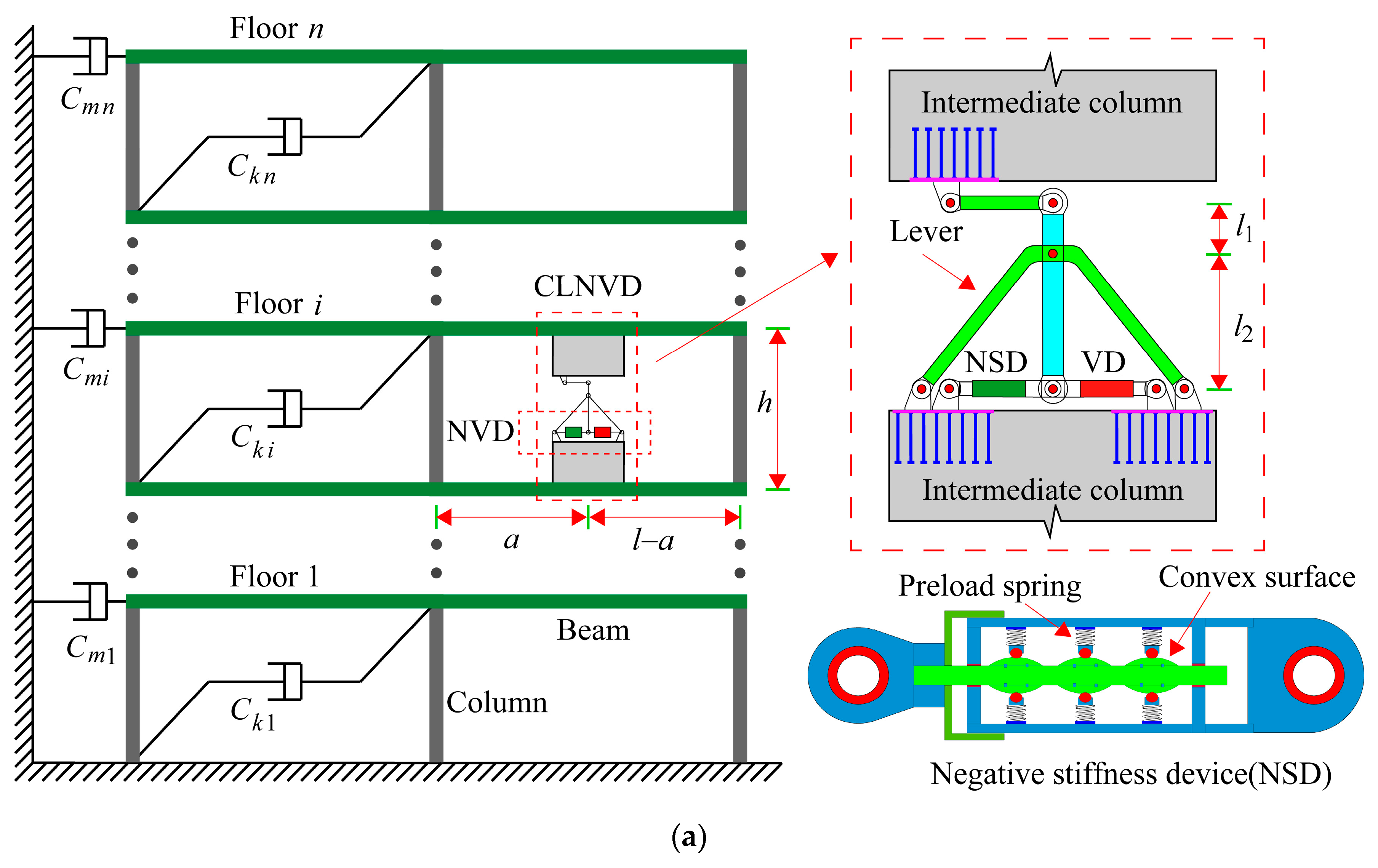
Figure 1. Intermediate column–lever negative stiffness viscous damper (CLNVD): (a) CLNVD; (b) NSD’s negative stiffness force; (c) hysteresis curves of NSD and NVD.
Applsci 14 07627 g001aApplsci 14 07627 g001b
Figure 2. Force analysis and deformation on the i-th story: (a) force analysis on the i-th story; (b) deformation under F action; (c) deformation under M action; (d) deformation under θ action; (e) deformation under △ action.
Applsci 14 07627 g002
Figure 3. Geometric amplification coefficient γ : (a) γ F ; (b) γ M ; (c) γ Δ .
Applsci 14 07627 g003
Figure 4. Schematic diagram of the CLNVD’s mechanical model and equivalent stiffness: (a) simplified mechanical model and Kelvin model; (b) k l e ; (c) k m c u p ; (d) k m c l o w .
Applsci 14 07627 g004aApplsci 14 07627 g004b
Figure 5. When α = 0.5 , effective displacement factor η d and stiffness amplification coefficient k a / ( γ i 2 k ) : (a) η d ; (b) k a / ( γ i 2 k ) .
Applsci 14 07627 g005
Figure 6. Schematic diagram of structure with CLNVDs.
Applsci 14 07627 g006
Figure 7. The impact of β and i m c on f d and f E : (a) impact of β on f d and f E ; (b) impact of i m c on f d and f E .
Applsci 14 07627 g007
Figure 8. The impact of i b / i b 1 on f d and f E : (a) impact of i b / i b 1 on f d and f E ( β = 0.1); (b) impact of i b / i b 1 on f d and f E ( β = 0.5); (c) impact of i b / i b 1 and β on f d and f E .
Applsci 14 07627 g008
Figure 9. The impact of i l e and χ on f d and f E : (a) impact of i l e / i l e 1 on f d and f E ; (b) impact of χ on f d and f E .
Applsci 14 07627 g009
Figure 10. The impact of c and α on f d and f E : (a) impact of c on f d and f E ; (b) impact of α on f d and f E ; (c) impact of c and α on f d and f E ; (d) η d and k d / k corresponding to f P E under changes in α .
Applsci 14 07627 g010
Figure 11. Impact of k N / k on f d and f E and the target value region of k N / k and k d / k : (a) impact of k N / k on f d and f E ; (b) impact of k N / k on k a / ( γ 2 k ) ; (c) corresponding k N / k and k d / k of different f d ; (d) target value region of k N / k and k d / k .
Applsci 14 07627 g011aApplsci 14 07627 g011b
Figure 12. Impact of inter-story displacement on f d and f E : (a) impact of U 1 on f d and f E ; (b) impact of χ and U 1 on f E ; (c) impact of i b and U 1 on f E ; (d) impact of c and U 1 on f E .
Applsci 14 07627 g012
Figure 13. The structure’s damping design flowchart.
Applsci 14 07627 g013
Figure 14. Three-dimensional schematic diagram of the structure and layout of the CLNVD: (a) 3D structural schematic diagram; (b) plane layout of the CLNVD; (c) scheme 1 (B-axis); (d) scheme 2 (B-axis); (e) scheme 3 (B-axis).
Applsci 14 07627 g014aApplsci 14 07627 g014b
Figure 15. Time–history response spectra of seven waves.
Applsci 14 07627 g015
Figure 16. The CLNVD’s f d and f E under fortification earthquakes and rare earthquakes: (a) f d ; (b) f E .
Applsci 14 07627 g016
Figure 17. NVD’s hysteresis curves of various schemes and combinations of k N / k and k d / k in Scheme 1: (a) NVD’s hysteresis curves; (b) values of k N / k and k d / k in Scheme 1.
Applsci 14 07627 g017
Figure 18. Inter-story displacement angle under fortification earthquakes and rare earthquakes: (a) fortification earthquakes; (b) rare earthquakes.
Applsci 14 07627 g018
Figure 19. Story shear forces under fortification earthquakes and rare earthquakes: (a) fortification earthquakes; (b) rare earthquakes.
Applsci 14 07627 g019
Table 1. Parameters of the improved TNVD components.
Column   Section Beam   Section Intermediate   Column     Section β χ   c k N
( mm × mm ) ( mm × mm ) ( mm × mm ) ( kN ( s / mm ) 0.5 ) ( kN / mm )
600 × 600400 × 8001600 × 2500.545−2
Table 2. Parameters of the structure.
StoryConcrete MaterialColumn SectionMain Beam SectionSecondary Beam Section
(mm × mm)(mm × mm)(mm × mm)
1C40700 × 700300 × 600200 × 400
2C40600 × 600300 × 600200 × 400
3–4C40550 × 550300 × 600200 × 400
5–9C35500 × 500300 × 600200 × 400
Table 3. Dynamic properties of the structure.
Mode123456
Period (s)1.601.581.380.560.540.48
DirectionX (E-W)Y (N-S)RotationX (E-W)Y (N-S)Rotation
Effective Mass (%)777676111212
Table 4. Parameters of the CLNVD.
SchemeStory β Beam   Sec tion Column   Sec tion χ   c k N
( mm × mm ) ( mm × mm ) ( kN ( s / mm ) 0.5 ) ( kN / mm )
Scheme 1 5–80.5400 × 8001700 × 35048−2
2–40.5400 × 8001700 × 350412−2
Scheme 2 5–80.2400 × 8001700 × 35048−2
2–40.2400 × 8001700 × 350412−2
Scheme 3 5–80.2400 × 8001700 × 350480
2–40.2400 × 8001700 × 3504120
Table 5. Damping ratios provided by CLNVDs under fortification earthquakes.
Earthquake WaveScheme 1Scheme 2Scheme 3
Manjil19.1%13.5%7.9%
Coalinga20.6%13.8%8.7%
Imperial Valley21.3%15.8%9.2%
Chi-Chi23.3%15.5%8.8%
Big Bear19.6%13.8%8.5%
Artificial wave 119.7%13.8%8.0%
Artificial wave 220.1%13.5%8.4%
Average of multiple waves20.5%14.2%8.5%
Table 6. Energy composition of rare earthquakes.
Energy CompositionScheme 1Scheme 2Scheme 3
Internal model damping/Input21.3%27.1%36.5%
Damper/Input77.9%70.8%57.4%
Dissipated inelastic/Input0.8%2.1%6.1%
Disclaimer/Publisher’s Note: The statements, opinions and data contained in all publications are solely those of the individual author(s) and contributor(s) and not of MDPI and/or the editor(s). MDPI and/or the editor(s) disclaim responsibility for any injury to people or property resulting from any ideas, methods, instructions or products referred to in the content.