1. Introduction
Ensuring that buildings in earthquake areas have good seismic performance has become one of the key tasks for building designers. Currently, the commonly used technical methods include seismic isolation strategy [
1,
2,
3], energy dissipation and vibration reduction passive control strategy [
4,
5,
6], semi-active control strategy [
7], and active control strategy [
8]. In comparison with seismic isolation strategy, the passive energy dissipation control strategy possesses the characteristics of having less impact on the construction process and construction time. Moreover, the related energy dissipation devices can be installed after the completion of the main structure. Meanwhile, in contrast to the other two kinds of control strategies, the passive control strategy has the following characteristics: it does not need external energy; relevant technical means are simple and reliable; the subsequent maintenance is extremely simple; and the overall cost is extremely low. In the passive control strategy, in comparison with metal dampers [
9] and friction dampers [
10,
11], viscous dampers are favored by engineers due to their lack of stiffness and strong energy dissipation capabilities. However, when the structure’s deformation is extremely small, or the damper’s linking component deformation is extremely large, the damper’s deformation will become very small, which cannot efficiently reduce the structure’s seismic response [
12,
13,
14]. Therefore, it is essential to put forward a damper which not only has a large displacement amplification capability but also has a low stiffness requirement for the brace.
The intermediate column damper [
15,
16] takes the upper and lower intermediate columns as connecting components for dampers and then installs them within the span of the beam. Therefore, its impact on building functionality is minimal. Lan et al. [
17,
18] studied the impact of the position of the column on the damper’s displacement and the structure’s vibration response as per vibration table experiments. The experimental results were as follows: when the damper system lies at the mid of the beam span, the damping ratio will be the highest, and the structure’s inter-story deformation will be the smallest. Other related researchers studied the optimal installation position of dampers in structures. For instance, Sonmez [
19,
20] adopted the artificial bee colony algorithm; Lan [
21] applied response surface methodology, and Bishop et al. [
22,
23,
24] employed the genetic algorithm to seek the dampers’ optimal installation location. However, in contrast to the amplification device, the improvement effect on those dampers’ displacement produced by the above-mentioned optimization method is poor. Therefore, it is essential to improve the traditional intermediate column damping system to enhance its displacement amplification effect.
In order to enhance the damper’s displacement, scholars put forward a variety of devices. Ribakov et al. [
25,
26,
27] utilized the slant support lever damping system to control the structure’s dynamic response and developed a structural optimization design program to realize the structural response close to the optimal control theory. Numerical simulation showed that the seismic response of structures that are equipped with lever damping systems was significantly improved. Yang [
28] proposed a symmetrical lever amplification-style oil damper and tested the vibration-reduction effect of the amplification-style oil damper through finite element simulation. He et al. [
29,
30] designed a lever amplification-style viscous damping wall and conducted a vibration table experiment on a steel frame installed with enlarged viscous damping walls. The results indicated that this amplification device could significantly improve the seismic safety of the structure. Meanwhile, Yang [
31] proposed a kind of joint damper with an amplification effect and studied the performance of this enlarged soft steel joint damper through numerical simulation. In addition to the above-mentioned lever amplification devices, toggle-style amplification devices are also widely applied in engineering. Constantinou et al. [
32,
33] proposed a toggle damping system utilizing crank connecting rod technology. The theoretical analysis results indicated that the toggle significantly increased the damper’s displacement. Moreover, the stronger the amplification capability of the toggle device is, the more sensitive it is to changes in the length of the connecting rod. Subsequently, Taylor [
34,
35,
36] and Sigaher [
37] proposed the improved toggle brace devices and scissor-style devices, respectively. On this basis, in order to reduce the impact on building functionality, Polat [
38] proposed an open damping amplification device, and Lan [
39] proposed a local toggle brace damper. Meanwhile, Kang et al. [
40,
41] proposed a seesaw amplification mechanism composed with a bracket, a seesaw, and a viscous damper. Through a dynamic analysis of the 6-floor framework attached to the mechanism, it was found that the seesaw mechanism had strong energy dissipation capacity. Meanwhile, it was pointed out that the focus of the mechanism design was to balance the damping coefficient and brace stiffness. However, the above-mentioned amplification devices either have an enormous impact on building function or are susceptible to small changes in the connecting rod’s length of the toggle or need a high stiffness of the brace component. As a result, these problems increase the difficulties of their extensive applications.
To significantly enhance the damper’s energy dissipation, the brace components or amplification devices connected to the damper themselves need to have a high stiffness. However, Javanbakh [
42] found that when the support is flexible, the negative stiffness device will aggravate the damper’s displacement. Currently, various forms of negative stiffness devices have been proposed successively. Nagarajaiah et al. [
43,
44,
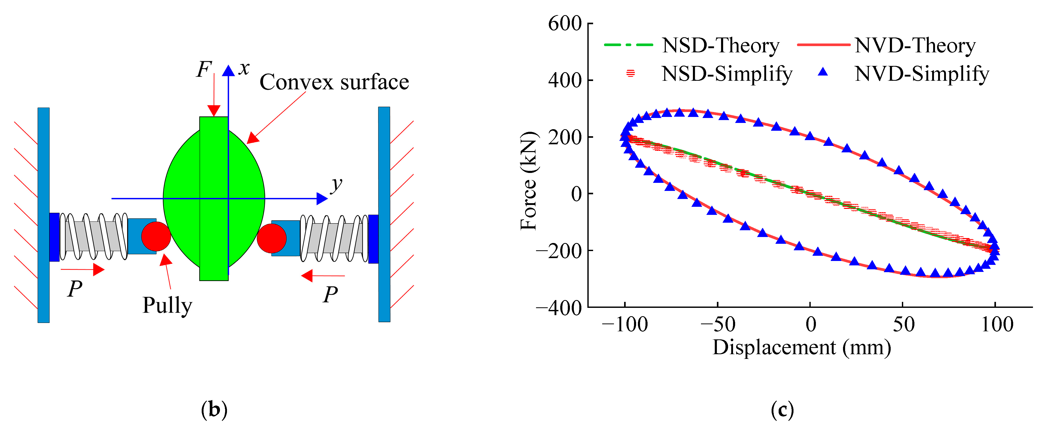
45] proposed realizing negative stiffness through preloading springs or gap springs. Meanwhile, Chen et al. [
46,
47] applied a preloading spring to the inclined surface to realize negative stiffness. Zhu [
48] launched a negative stiffness damper on the basis of turbine damping and permanent magnets. Sun [
49] put forward a double triangular damper and applied it to replace traditional lead rubber isolation bearings in the foundation isolation system. Numerical simulations show that the damping system has a significant vibration isolation effect. Zhou [
50] analyzed the multimodal seismic control effect of the negative stiffness damping system on cables, and the results indicated that a small negative stiffness damper equipped with flexible braces can achieve high damping effects. Wang [
51] analyzed the negative stiffness damper’s impact on the dynamic responses of the structures under pulse excitation, random excitation, and earthquake excitation. The results revealed the following: adding the negative stiffness device to the flexible brace damper significantly increased the damper’s energy dissipation while effectively reducing the structure’s displacement and acceleration responses. The energy dissipation capacity of the damper was improved by 5 times to 16 times, even if the ratio of the damper’s damping to the structure’s damping was lowered to 2.8%.The above studies indicate the following: negative stiffness devices are capable of improving the performance of dampers significantly while decreasing the stiffness demands on the damper’s connecting components. However, there is currently limited research on the combination of amplification devices and negative stiffness damping systems, which will be a new and effective passive control technology.
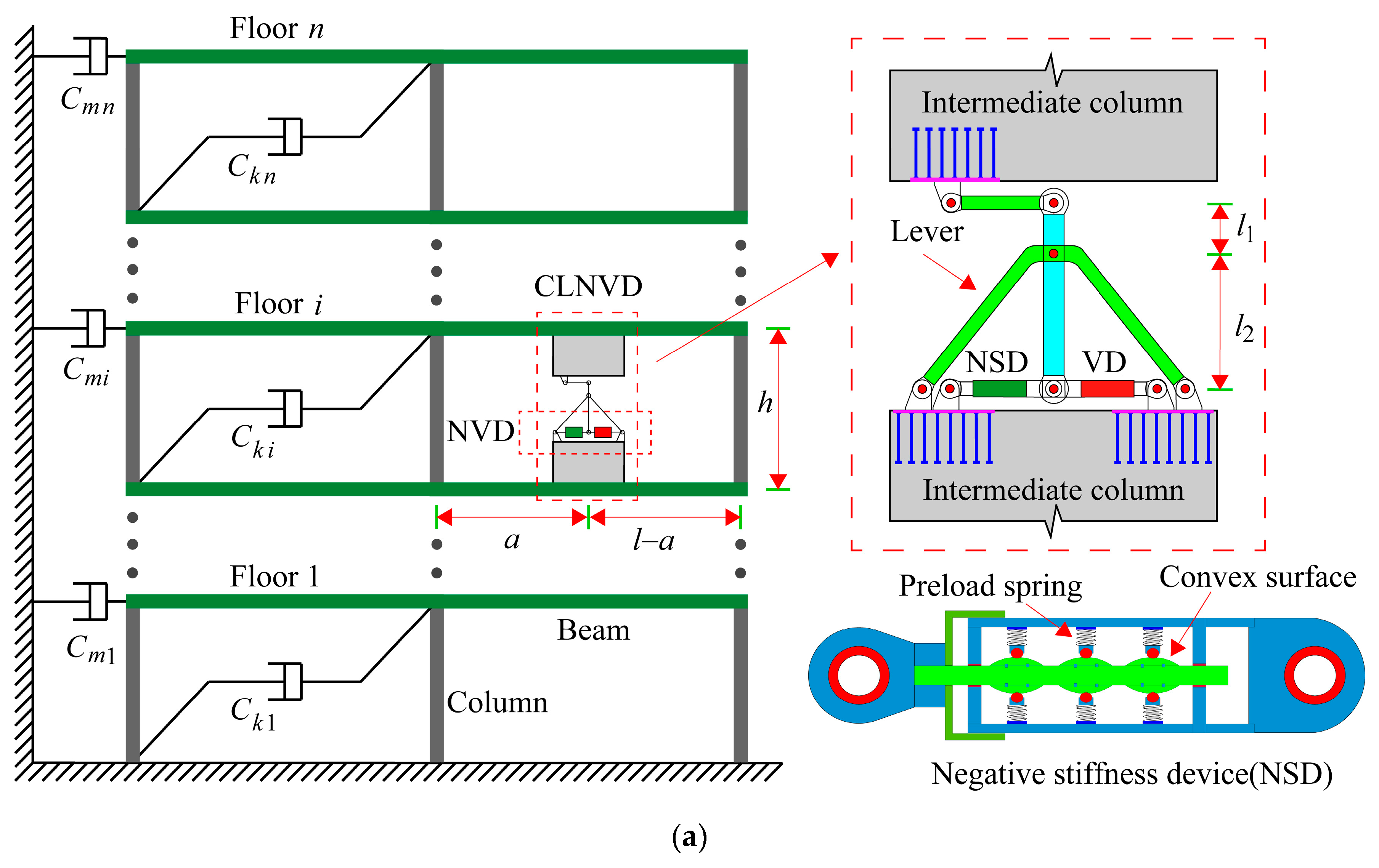
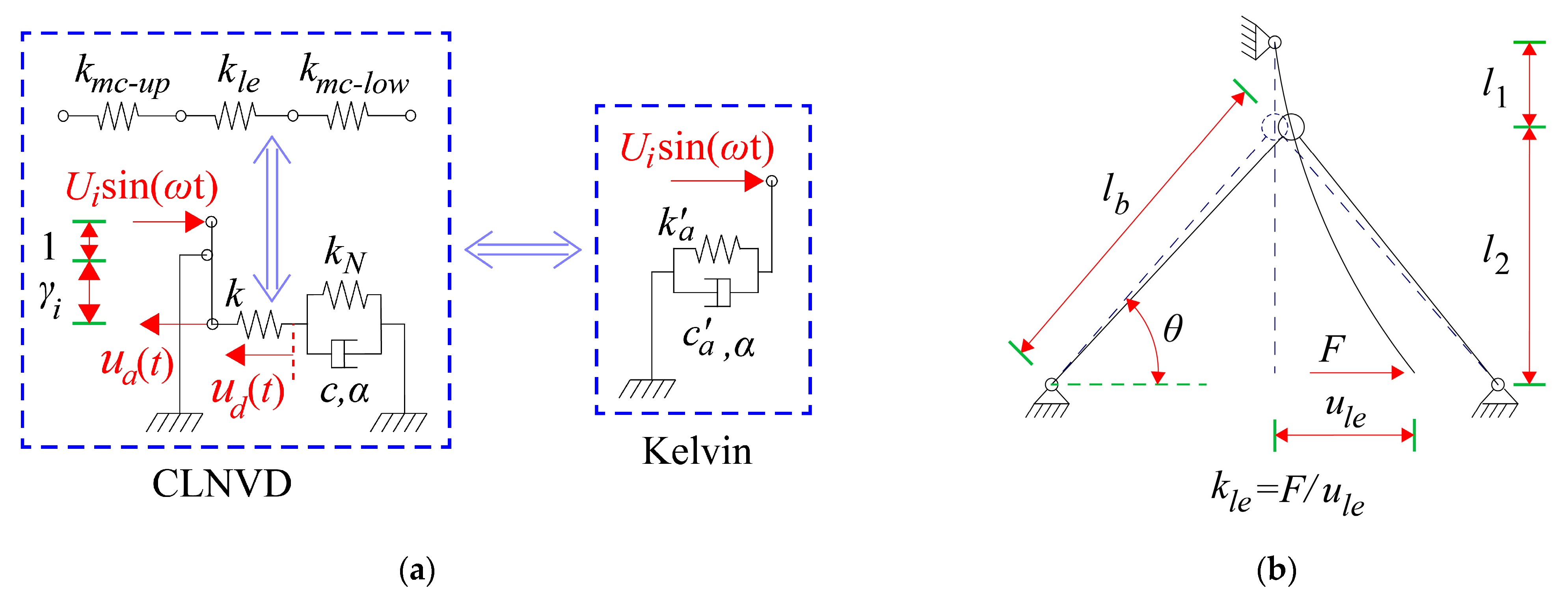
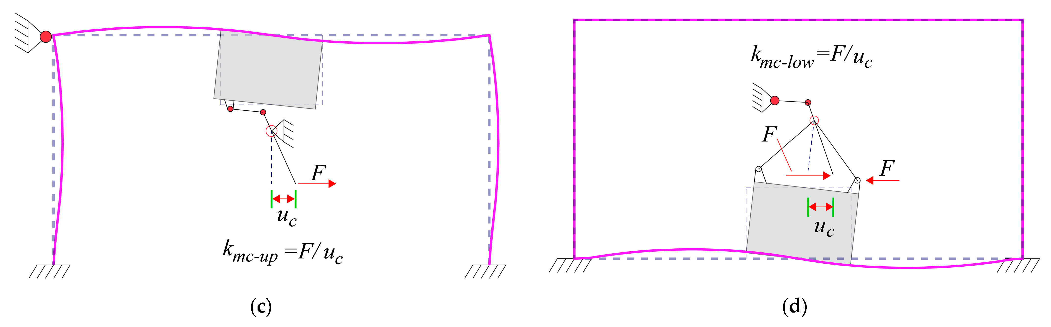
Aimed at improving the damper’s displacement, decreasing the stiffness requirements on the damper connecting components, and minimizing the obstruction to building space, this paper introduces the intermediate column–lever negative stiffness viscous damper (CLNVD). The intermediate column–lever negative stiffness viscous damper (CLNVD) consists of an intermediate column, a lever, a negative stiffness device, and a viscous damper. In contrast to the displacement amplification effect of the toggle device, which is highly sensitive to changes in the length of the toggle’s connecting rod, the amplification capability of the CLNVD is relatively stable. In comparison to the traditional lever amplification devices, the CLNVD has less impact on building space because it can be flexibly installed within the span of the beam. In contrast to the traditional intermediate column damper, the CLNVD has a greater displacement amplification effect. This makes the cost of the CLNVD become lower under the same control effect on the seismic response of the structure. Meanwhile, due to the negative stiffness device, the CLNVD further reduces its stiffness requirements for the intermediate column and lever and further increases the damper’s deformation and energy dissipation.
Meanwhile, this paper introduces the displacement amplification coefficient fd and energy dissipation coefficient fE to assess the function of the CLNVD. Specifically, in this paper, the geometric magnification coefficient is employed to describe impacts of the CLNVD’s position on the CLNVD’s amplification ability; the effective displacement coefficient is utilized to present weakening of equivalent stiffness on the CLNVD’s amplification ability, and the relationship between geometric magnification coefficient and effective displacement factor with fd and fE is established. Subsequently, the geometric magnification coefficient is analyzed and derived. An equivalent simplified model for CLNVD is established, and the effective displacement factor is derived. The variation in CLNVD’s fd and fE with different factors, such as the position of the CLNVD, lever’s amplification coefficient, the beam’s bending line stiffness, damping index, damping coefficient, and inter-story displacement, is expounded. Subsequently, a damping design method considering CLNVD optimization is proposed. Ultimately, CLNVD’s strong displacement amplification capability is verified through engineering examples. Meanwhile, the effectiveness of the optimum design method is verified through the comparison among the three schemes.
3. Parameter Analysis and Optimization Design
The coefficients
and
of CLNVD are jointly affected by the intermediate column’s position
, the lever’s amplification factor
, the bending line stiffness
of the beam, negative stiffness
, and damping coefficient
. For the convenience of parameter analysis, the single-story structure shown in
Figure 6 is taken as the analysis object.
For single-story structures,
. Combining Equations (2)–(4), (9), (10), and (18), we obtain the following:
where
is calculated by Equation (11), and
is calculated by Equation (17);
is the inter-story displacement, and
is the structural stiffness proportional damping coefficient. For
, we take the first modal frequency of the structure.
When the damping index , Equation (17) cannot be directly employed since is unknown. However, the following iterative method is applied. This iterative method is as follows:
- (1)
The damper displacement is assumed to be equal to the inter-story displacement .
- (2)
is substituted into Equation (17) for calculation, and Equations (20) and (21) are utilized to calculate and .
- (3)
The error is calculated. When , is made to be equal to , and steps from 2 to 3 are repeated. When , the iteration ends.
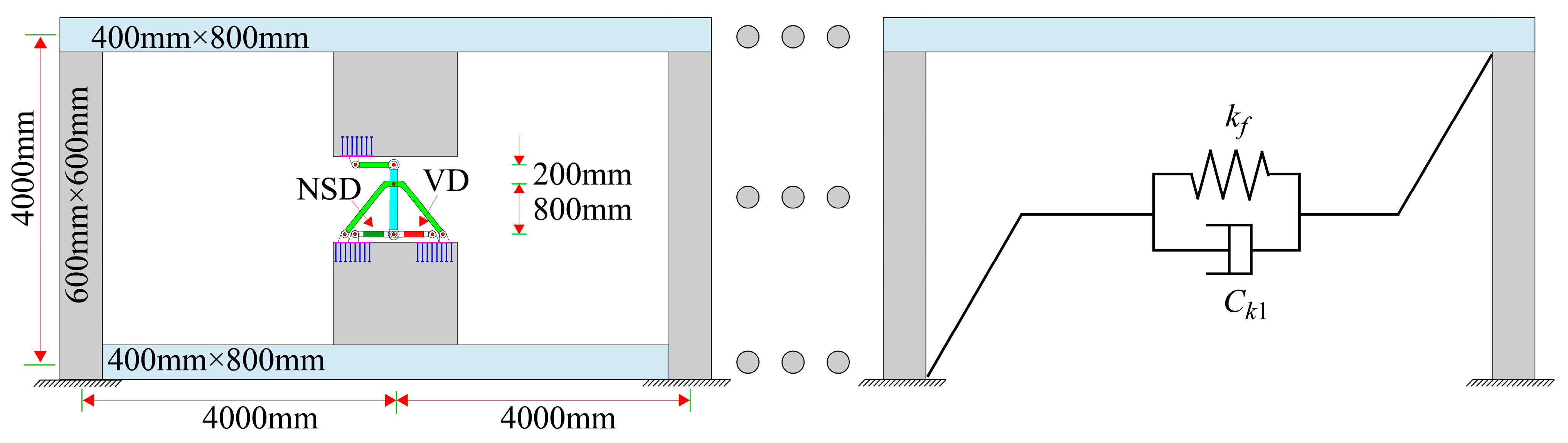
For the convenience of discussion, an analysis is conducted on the single-story structure illustrated in
Table 1. The material of the lever amplification device is Q235, and the concrete material grade of the structure is C35. The cross-section of the lever box is 230 × 140 × 25 × 25 (unit: mm), with the length of 1000 mm; the box section of slant support is 200 × 200 × 25 × 25 (unit: mm). The structure maintains elasticity, and the modal frequency is
; the structure’s stiffness proportional damping is
, and the inter-story displacement under the circumstance of fortification earthquakes is
. The method adopted for parameter analysis in this section is to keep other parameters unchanged and observe the impact of changing a certain parameter on the efficiency of CLNVD.
3.1. Parameter Analysis
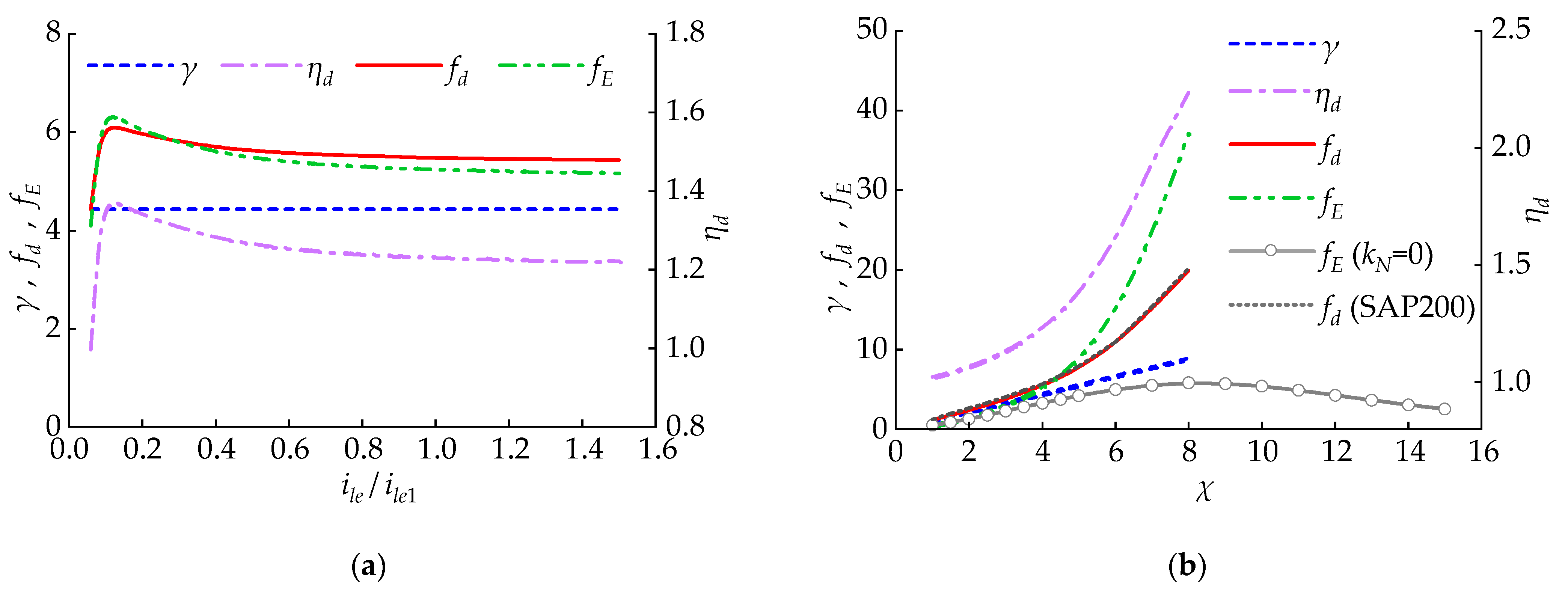
3.1.1. Impact of the Intermediate Column’s Position and Its Bending Line Stiffness
The intermediate column’s position
affects CLNVD’s
and
.
Figure 7 reveals the curves of
,
,
, and
with
. As is described in
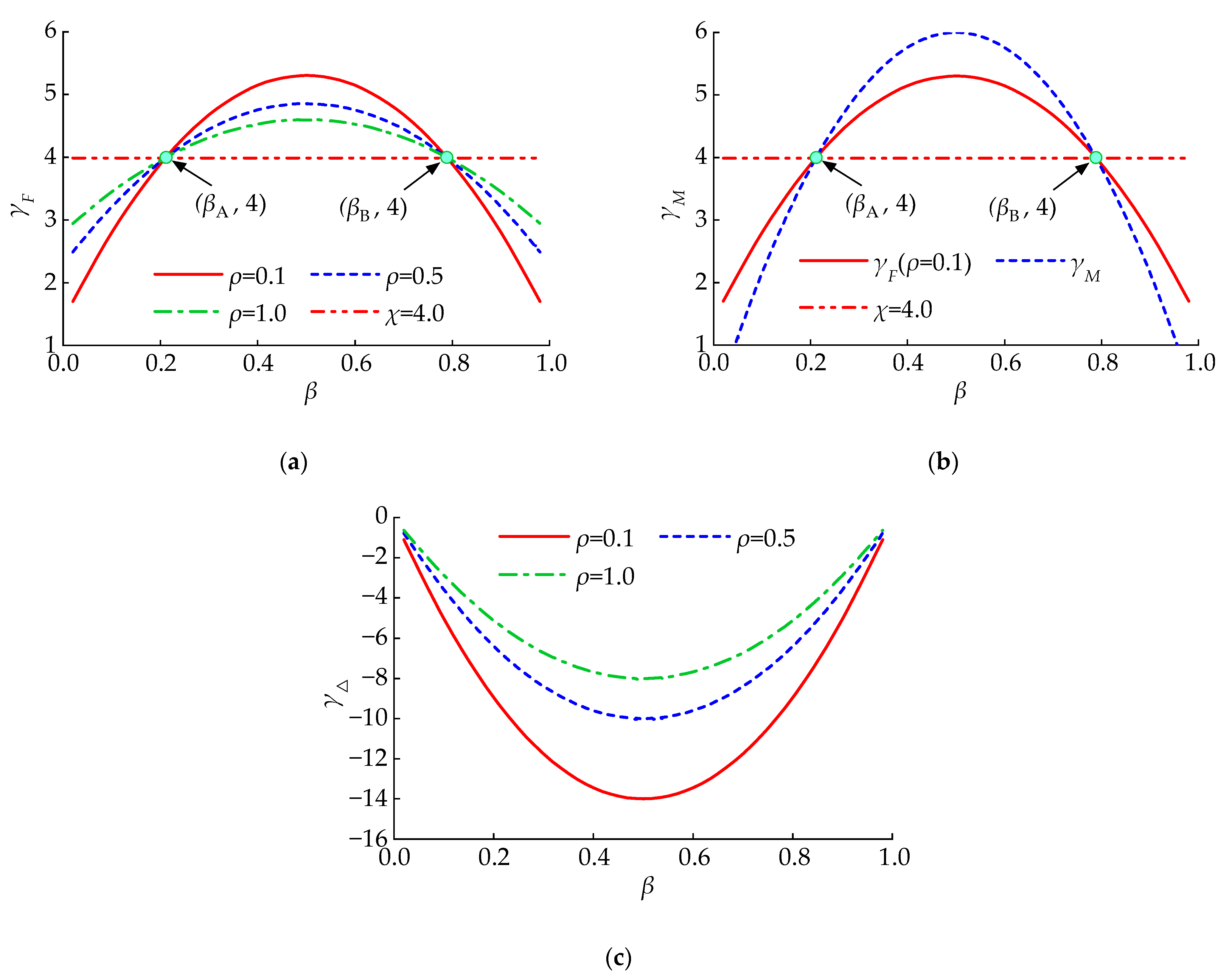
Figure 7a, when the intermediate column moves from the ends of the span to the middle of the span,
increases, while
increases at first and decreases subsequently. However, the increase in
is even greater. Therefore, when
,
and
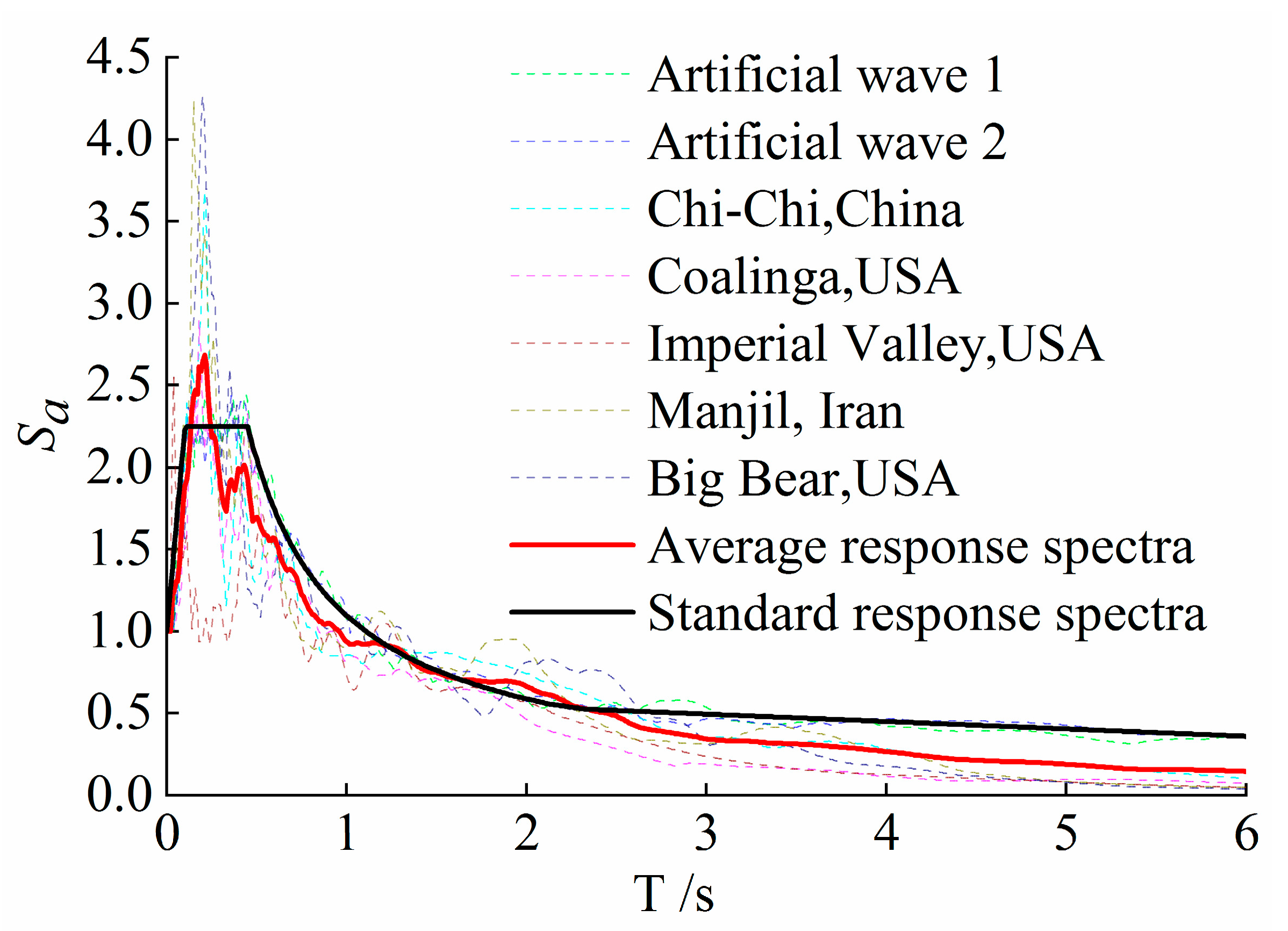
reach its maximum value. SAP2000 (Version 23.1.0) is used for numerical simulation, and seven seismic waves from
Section 4.2 are selected. The analysis results of
in this section are taken as the average of the seven seismic wave calculation results. The results indicate that the theoretical calculation results of
are highly consistent with the numerical simulation results. In
Figure 7b,
refers to the intermediate column’s bending stiffness with the cross-section of 1600 mm × 250 mm. As is displayed in
Figure 7b,
and
rapidly increase at first, and then slowly decrease with the increase in
. A larger cross-section of the intermediate column is not conducive for CLNVD to obtain the peak value of
and
. In order to ensure that CLNVD has good energy consumption capacity, the CLVD is required to lie at the middle span under the condition that the building space allows this.
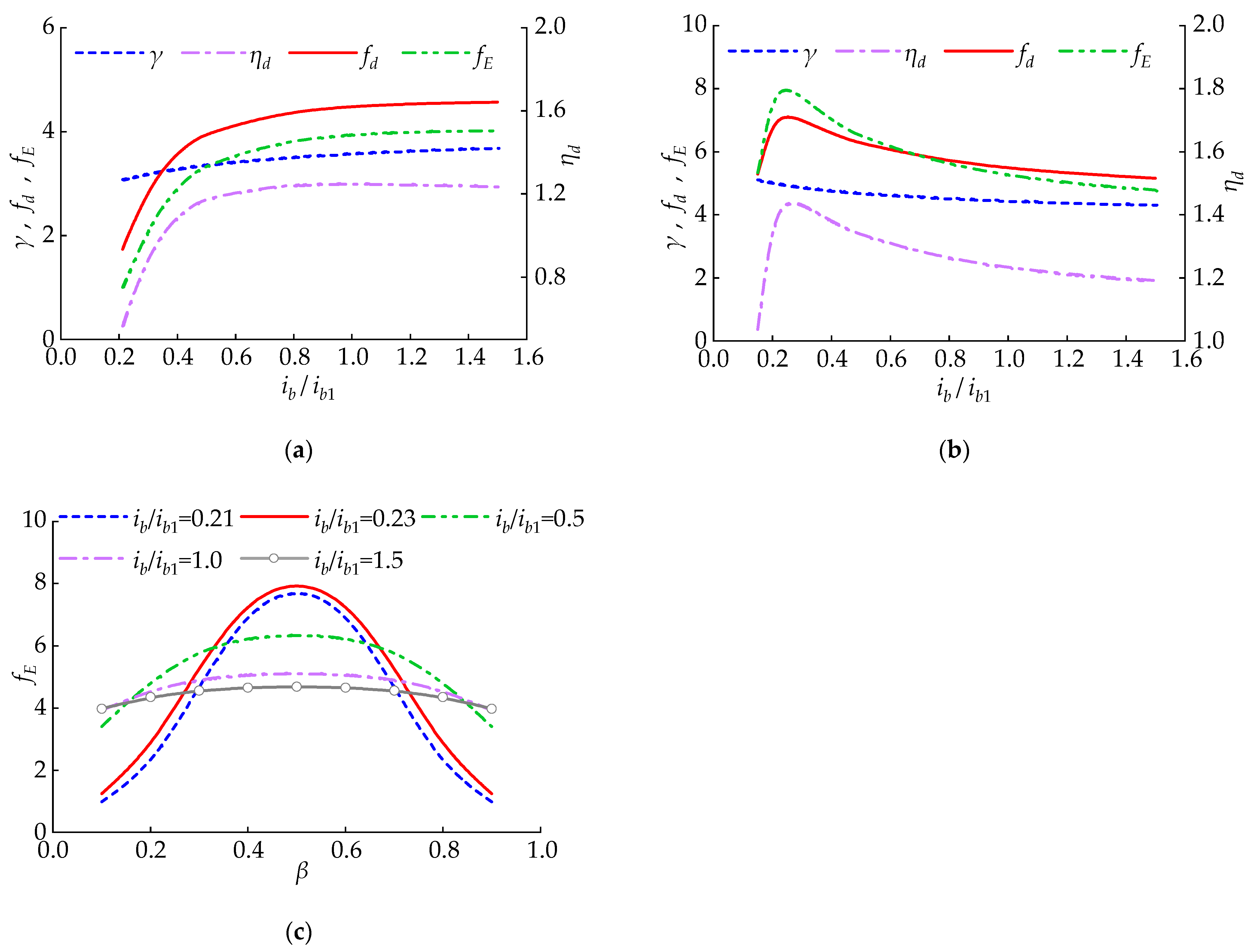
3.1.2. Impact of Beam’s Bending Line Stiffness
This section expounds the law of
and
as the beam’s bending line stiffness changes. In
Figure 8,
refers to the beam’s bending stiffness with the cross-section of 400 mm × 800 mm. When the intermediate column’s position
changes,
and
do not change in the same way with
. As is shown in
Figure 8a, when
,
and
increase with the increase in
. Hence,
and
increase as
increases. As is revealed in
Figure 8b, when
, with the increase in
,
slowly decreases, and
first increases and then decreases. Therefore, as
increases,
and
first rapidly increase and then decrease. For different
, the impact law of
on
is shown in
Figure 8c. From
Figure 8a–c, it is concluded that CLNVD located at the mid span can achieve higher
with a smaller beam cross-section.
3.1.3. Impact of Lever’s Bending Line Stiffness and Leverage Amplification Coefficient
This section expounds the variation in
and
with the lever’s bending line stiffness
as well as the lever’s amplification coefficient
. In
Figure 9,
refers to the bending line stiffness with the box section of 230 × 140 × 25 × 25 (unit: mm). The impact of the stiffness and amplification coefficient is not the same. As is shown in
Figure 9a, like
,
and
rapidly increase at first and then decrease slowly with the increase in
. As is shown in
Figure 9b, when
, there exists an optimal leverage amplification coefficient
which enables
to reach the maximum. When
,
and
increase with the increase in the lever’s amplification coefficient
. However, this does not mean that larger options can be selected without limitations. The larger
causes the lever and beam to bear a greater force, which requires a larger cross-section to maintain elasticity. SAP2000 (Version 23.1.0) is used for numerical simulation. The results indicate that the theoretical calculation results and numerical simulation results of
are very consistent under different
χ conditions.
3.1.4. Impact of the Damping Coefficient and Damping Exponent
This section expounds the variation law of
and
with the damping index
as well as the damping coefficient
. From
Figure 10a,b, we obtained a conclusion that
gradually decreases when increasing the damping coefficient
or index
. Therefore,
gradually decreases, while
first increases and then reduces. Therefore, it is necessary to select appropriate index
and damping coefficient
to enable
to reach the largest value. Under different exponent
, the variation law of
with the change in the damping coefficient
is shown in
Figure 10c.
in
Figure 10c refers to the peak value of the energy dissipation coefficient
.
Figure 10d presents the curve of
and
corresponding to
in
Figure 1c with the index
. According to
Figure 10d, it is indicated that
reaches the maximum value when the
and
make
or
.
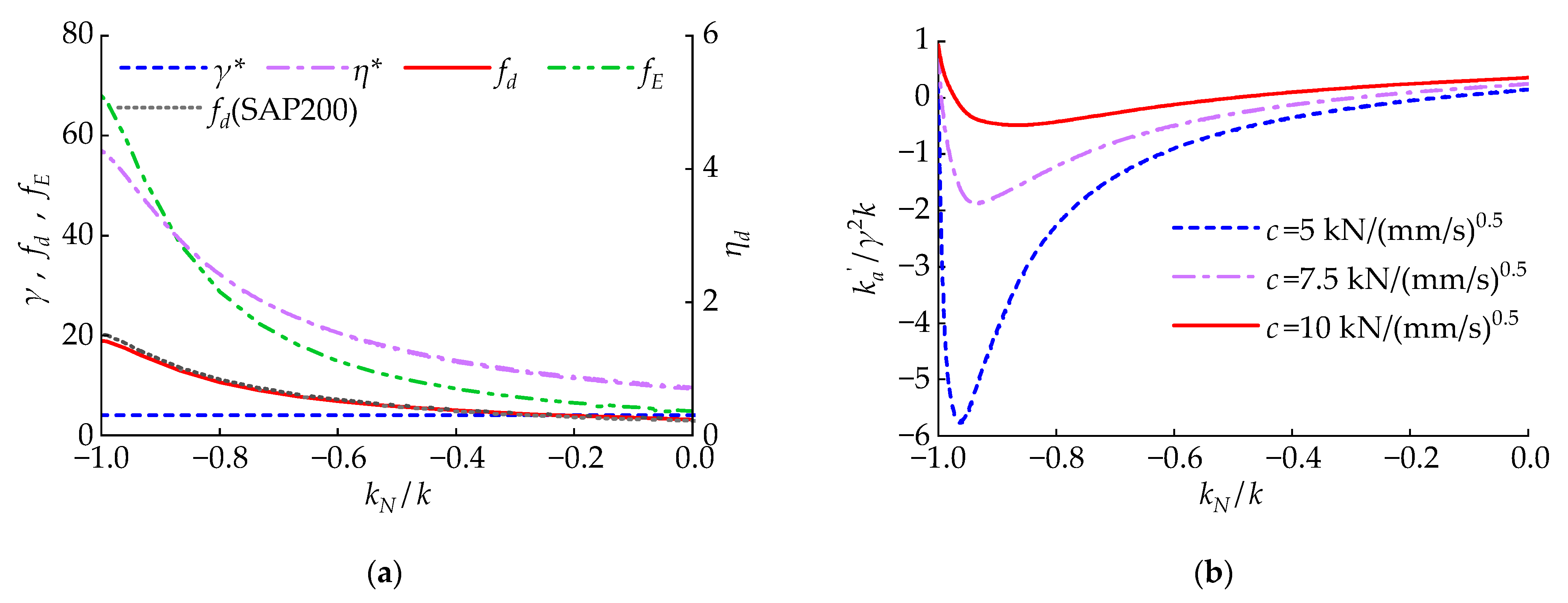
3.1.5. Impact of NSD’s Negative Stiffness
This section analyzes the variation in
and
with the changes in NSD’s
. As is shown in
Figure 11a, when
decreases,
gradually increases. Therefore,
and
gradually increase. From
Figure 11b, it is concluded that when
decreases,
decreases at first and then increases. Moreover, a smaller
will give CLNVD larger negative stiffness. Therefore, the size of
should be controlled to make CLNVD achieve a higher
while avoiding an influential decrease in the structure’s overall stiffness. SAP2000 (Version 23.1.0) is used for numerical simulation. The results indicate that the theoretical calculation results and numerical simulation results of
are very consistent under different
conditions. The CLNVD can be guaranteed to achieve a high
by controlling the size association between
and
. The reference [
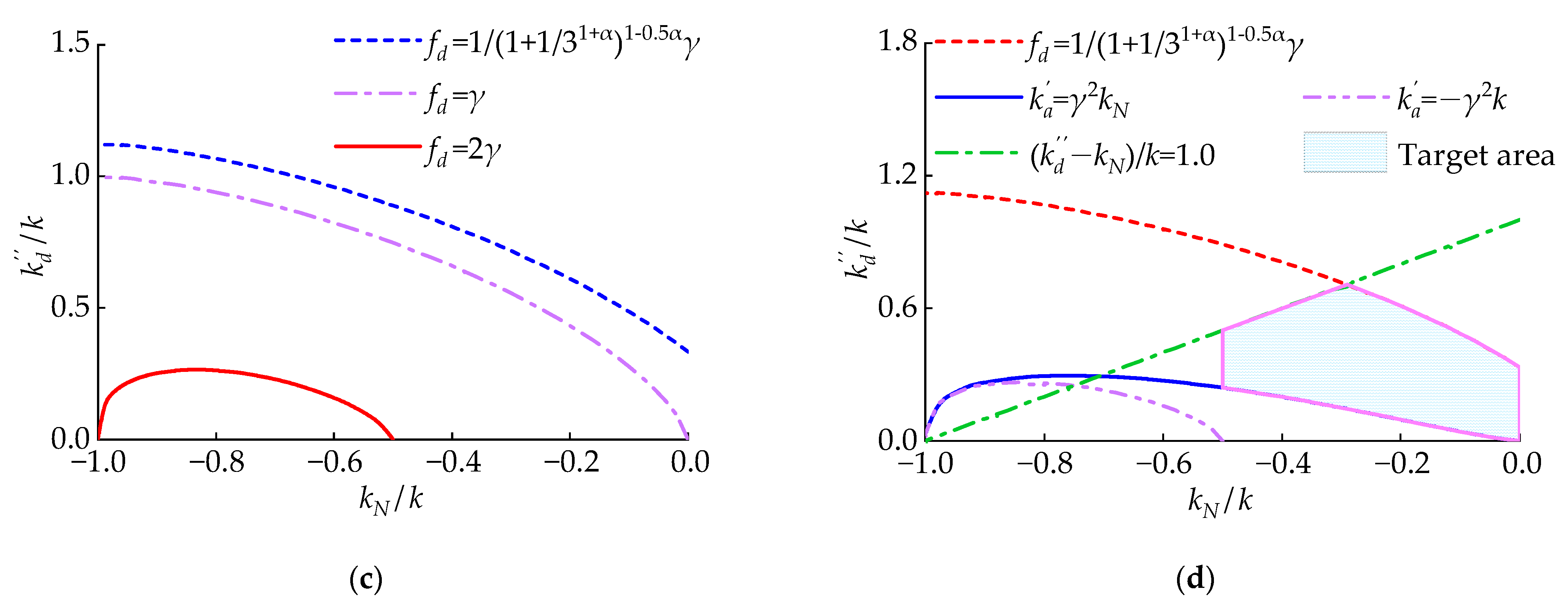
54] requires that the ratio of the viscous damper’s loss stiffness to the brace stiffness is less than 1/3. When
,
, and
, the size relationship between
and
can be calculated from Equation (22) as follows:
The size of CLNVD’s
can also be controlled by controlling the size association between
and
. When
or
, the size association between
and
are showed in Equation (23).
Combining Equation (22) as well as
Figure 11c, we can see that when
,
. Combining Equation (23) and
Figure 11d, we can see that when
,
. When
,
. Through Equation (19), it can be obtained that when
,
. We can see from
Section 3.1.4 that when
,
increases as the damping coefficient
increases. Thus, according to the above analysis, it is recommended that the target area in
Figure 11d should be taken as the range of values for
and
. Within this target area, we can see the following:
;
;
rises when increasing the damping coefficient
.
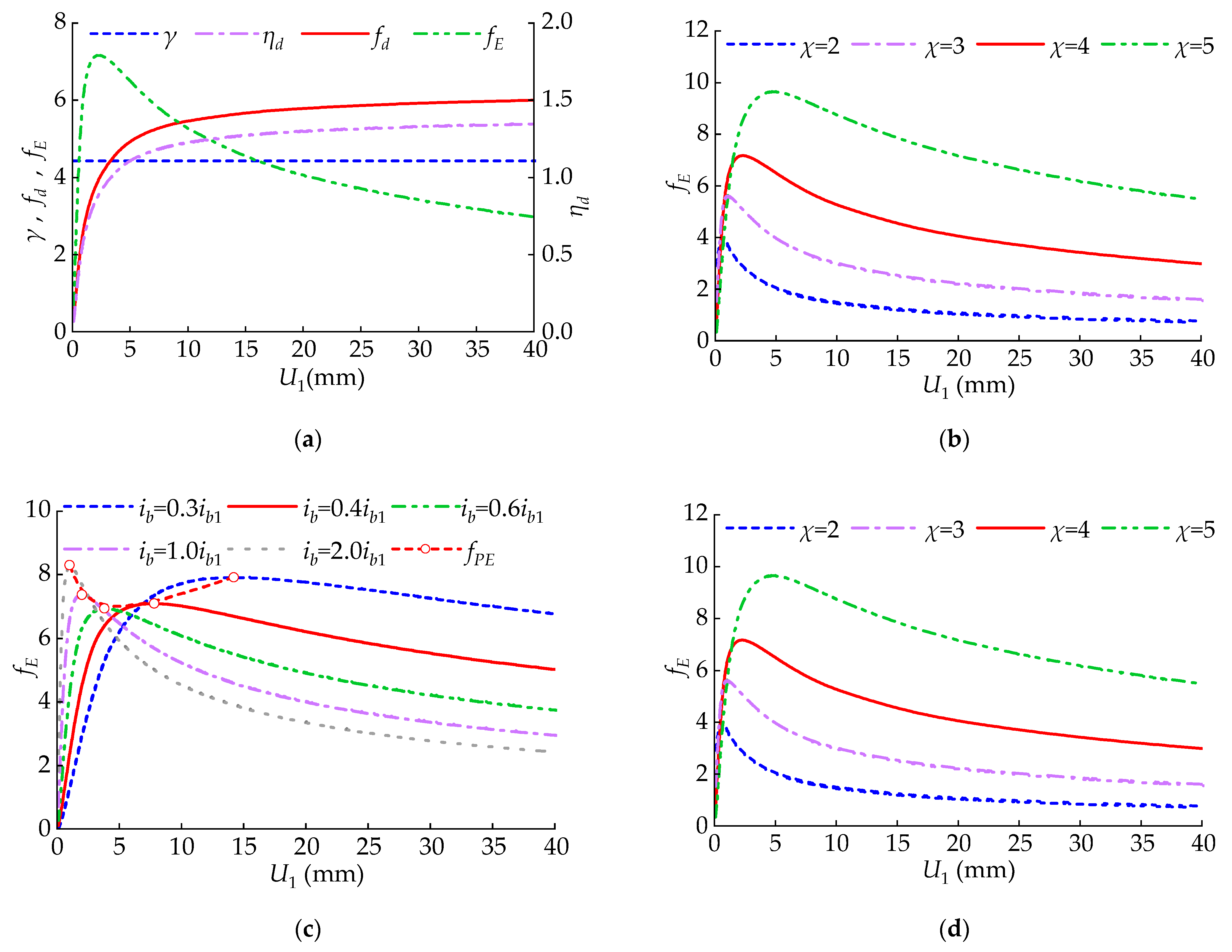
3.1.6. Impact of Inter-Story Displacement
This section explores the variation law of
and
with the inter-story displacement
.
affects
and
by means of changing the loss stiffness
of VD. As is shown in
Figure 12a, when increasing
,
gradually increases, and
increases first and later decreases. Increasing the lever’s amplification coefficient
can increase
, which has been discussed in
Section 3.1.3. As is shown in
Figure 12b, when
is larger, increasing
has a significant improvement on
. However, when
is small, increasing
does not have a good effect on improving
. In
Figure 12c,
refers to the beam’s bending line stiffness with the section of 400 mm × 800 mm. As is shown in
Figure 12c, when
is small, increasing
has a significant improvement on
. However, when
is larger, increasing
will lead to a decrease in
. Meanwhile, increasing
causes the peak energy-consumption efficiency
to decrease first and then increase. In
Figure 12d,
. As is revealed in
Figure 12d, when
is larger, increasing the damping coefficient
has a significant improvement on
. However, when
is smaller, a higher damping coefficient
leads to a decrease in
. Meanwhile, increasing the coefficient
does not change the magnitude of the peak energy consumption coefficient
. Moreover, it will cause
to move towards larger displacements.
3.2. CLNVD’s Optimum Design
3.2.1. Optimum Strategies for the CLNVD
In order to ensure that the CLNVD has a large coefficient
and coefficient
under the circumstance of frequent earthquakes (or fortification earthquakes), on the basis of the analysis in
Section 3.1, the following steps are adopted to optimize the CLNVD:
- (1)
The position of the intermediate column is selected, as well as the beam section and lever amplification factor ; the line stiffness ratio of beam to column is calculated. According to Equations (9) and (10), the geometric amplification coefficient is calculated. is judged to estimate whether it is higher in comparison with the pre-set target of . If it is not higher, the following methods are applied: to increase , or to decrease .
- (2)
CLNVD’s parameters (such as intermediate column section, lever section, negative stiffness, damping coefficient, and damping index) are selected so that the values of
and
are within the target area (See
Figure 11d). The inter-story displacement target value and the iterative method in
Section 3.1 can be used to calculate
; the
is calculated through Equation (18).
- (3)
and are substituted into Equation (3) to calculate the displacement amplification coefficient , and Equation (4) is utilized to calculate the energy dissipation coefficient .
- (4)
is judged if the predetermined goals are met. If not, the following methods are applied for optimization: to enhance the stiffness
and damping coefficient
; to enhance the stiffness
and the lever’s coefficient
; to increase the lever’s coefficient
and reduce the damping coefficient
; or to reduce the NSD’s negative stiffness
. It is necessary to verify again if
and
are within the region proposed in
Section 3.1.5, and Step (3) and Step (4) should be repeated. If
cannot meet the set target when
is on the upper limit of the target region in
Figure 11d, we should increase the beam section and return to Step (3).
3.2.2. Optimum Design for Structures with the CLNVD
With the aim to evaluate the damping contribution of dampers to the overall structure and control the structure‘s deformation, the current vibration-reduction design methods mostly utilize additional damping ratios as well as the maximum inter-story displacement angle as control objectives. For additional CLNVD structures, this paper proposes a seismic design method with coefficient
, coefficient
, maximum inter-story displacement angle, and additional damping ratio as control objectives. In contrast to the structure without the CLNVD, the stiffness and damping properties of the multi-story structures with the CLNVD vary greatly, and such changes are difficult to predict before the actual calculation. Therefore, for the vibration-reduction design of the additional multi-story CLNVD structures, the current design method is to conduct trial calculations, while ensuring that CLNVD has a high energy consumption, until the proposed design goals are met. During the trial calculation process, it is necessary to utilize the optimization strategy in
Section 3.2.1 to optimize CLNVD. Subsequently, the design is conducted according to the vibration-reduction design process in
Section 3.2.2.
Figure 13 illustrates the vibration-reduction design flowchart. The specific design steps are as follows:
- (1)
The target values are set for , , maximum inter-story displacement angle, and additional damping ratio.
- (2)
The stiffness ratio damping
of the structure, the seismic response of structures without CLNVD, and the seismic response of structures with additional expected damping ratios are calculated. The floors with the CLNVD layout based on the seismic response of the structure without the CLNVD are selected, and the number of CLNVDs based on the building area (a ratio of building area to number of dampers between 100 and 200 is more reasonable) is selected. The number of CLNVDs for each floor based on the total number of CLNVDs and the layout floor is set. The parameters of CLNVD are set, and CLNVD is optimized according to
Section 3.2.1.
- (3)
The time history analysis is conducted under the circumstance of frequent or fortification earthquakes, and it is judged whether , , damping ratio, and displacement angle satisfy the goals. If not, we should increase the quantity of the CLNVDs or return to Step (2) for optimum strategies.
- (4)
The time history analysis is conducted under the circumstance of rare earthquakes, and it is judged if the displacement angle satisfies the goals. If the goals are not satisfied, we should raise the quantity of the CLNVDs and return to Step (3).
When the viscous damper is linear, the loss stiffness of the damper does not change with the displacement of the damper, thus avoiding the usage of iterative programs. When the viscous damper is nonlinear, if no iteration is carried out, the approximate formula for the damper loss stiffness provided in the reference [
53] can be used for relevant calculations, while the accuracy of the approximate formula is not ideal. The relevant parameters of CLNVD are selected in the target region in
Figure 11d, which will enable CLNVD to have a large displacement amplification factor and avoid providing a large negative stiffness to the structure. Hence, for single-story structures and linear viscous dampers, relevant parameters can be directly selected in the target area of
Figure 11d for ideal CLNVD design. For nonlinear viscous dampers and multi-story structures, the damping design of additional CLNVD structures needs to follow the design process in
Section 3.2.2.
5. Conclusions
The CLNVD consists of the viscous damper, the negative stiffness device, the lever, and the intermediate column, which has a low demand for stiffness of the connecting components and enhances the damper’s displacement. In this paper, energy dissipation coefficient fE and displacement amplification coefficient fd are proposed to intensively assess the CLNVD’s performance. The coefficient γ is introduced to describe the impact of the intermediate column’s position on the CLNVD’s amplification capability, and the factor ηd is introduced to describe the weakening of the equivalent stiffness on the CLNVD’s amplification capability. Moreover, the impacts, such as column’s position, beam’s stiffness, lever’s amplification coefficient, negative stiffness, damping coefficient, and inter-story displacement on CLNVD’s fd and fE, are studied. On this basis, this paper proposes a damping design method to optimize the CLNVD’s amplification capability. The main conclusions are as follows:
(1) The CLNVD can employ fd and fE to, respectively, describe its displacement amplification capability and energy dissipation capability. The coefficient fd is related to the geometric amplification coefficient γ as well as the effective displacement factor ηd.
(2) CLNVD’s fd and fE will be maximized, and fE will increase first and then decrease as the beam’s stiffness increases when the column‘s position is β = 0.5.
(3) The amplification capability of CLNVD will increase when increasing the lever’s amplification coefficient χ. When the negative stiffness is 0, there exists an optimum lever amplification coefficient that maximizes CLNVD’s fE.
(4) There exists an optimal combination of damping coefficient c and index α that maximizes CLNVD’s fE. Under this optimal combination, c and α need to satisfy = 1 + kN/k or ηd = 1/[2(1 + kN/k) 1+α] 1−0.5α.
(5) In contrast to the intermediate column damping system or the intermediate column–lever damper, the negative stiffness device enhances the displacement of CLNVD. In order to enable CLNVD to obtain greater displacement while avoiding providing too much negative stiffness, it is very necessary to make
kN/
k and
kd″/
k within the target area in
Section 3.1.5. Within this area,
fd ≥ 1/(1 + 1/3
1+α)
1−0.5αγ,
γ2kN ≤
ka′, and
fE increases when increasing damping coefficient
c.
(6) In order to enable CLNVD to have high energy dissipation capacity in both small and large displacements, the following methods can be utilized: to increase χ and ib simultaneously; to increase ib and c; or to increase χ while decreasing c.
(7) In vibration-reduction design, applying the optimization design method in
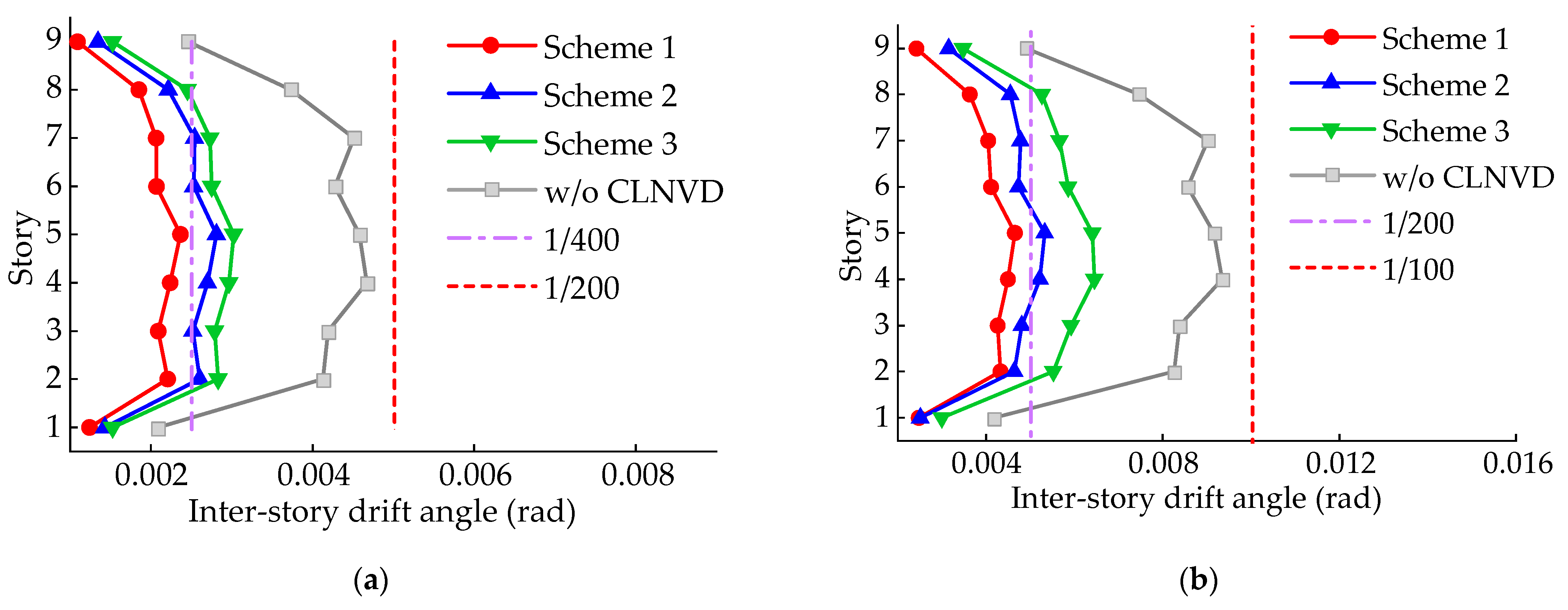
Section 3.2 can enable CLNVD to effectively control structure’s seismic response. The CLNVD provides a damping ratio of 20.5% in Scheme 1 under fortification earthquakes. Under the circumstance of rare earthquakes and fortification earthquakes, the inter-story displacement has a 50% reduction effect. Meanwhile, this optimization design method can provide a reference for vibration-reduction design in other types of negative stiffness dampers with amplification function.


