Article

Dynamic Instability Investigation of the Automotive Driveshaft’s Forced Torsional Vibration Using the Asymptotic Method

Department of Mechanics “Radu P. VOINEA”, National University of Science and Technology Politehnica Bucharest, 060042 Bucharest, Romania
*
Author to whom correspondence should be addressed.
Appl. Sci. 2024, 14(17), 7681; https://doi.org/10.3390/app14177681
Submission received: 29 July 2024 / Revised: 23 August 2024 / Accepted: 26 August 2024 / Published: 30 August 2024

Abstract

:

Featured Application

The first-order asymptotic method (FOAM) is used to analyze the dynamic instability in the area of principal parametric resonance (APPR) for the automotive driveshaft’s (AD) forced torsional vibration (ADFTV).

Abstract

This paper aims to investigate using FOAM to analyze the dynamic instability in the APPR for ADFTV based on a dynamic model (DMADFTV). The DMADFTV considers the following aspects: AD kinematic nonuniformity (ADKN), AD geometric nonuniformity (ADGN) of inertial characteristics for the spinning movements (ICSM) of the AD elements (ADE), and the excitations induced by the gearbox–internal combustion engine modulations. The DMADFTV is considered the already-designed dynamic model developed by the first author of the ADFTV in a previous publication. This DMADFTV was used to compute the stationary frontiers of instability and the nonstationary spectral velocity amplitude (NSVA) versus nonstationary spectral amplitude (NSA) in the configuration space in transition through APPR, using the FOAM. The use of FOAM is much more versatile, from the analytical point of view, than the method of multiple scales and allows the computation of the NSA and the NSVA in the APPR. In contrast, these computations cannot be performed using the harmonic balance method. MATLAB Software R 2017 was developed based on DMADFTV and used the FOAM to compute the stationary frontiers of instability and the NSVA versus the NSA in transition through APPR for the ADFTV. The numerical results were compared with the experimental and numerical data published in the literature, finding agreements. The computation of the NSVA versus NSA in the configuration space using FOAM represents a method of detection of the chaotic manifestation of ADFTV.

1. Introduction

The present work investigates the ADFTV, taking into consideration the following physical characteristics and phenomena: the fact that the links of the ADE do not manifest the property of isometry due to the ADKN and ADGN [1,2], and the ADE’s links are even considered CVJs (constant velocity joints); the effect of the torque loads, such as the entry gearbox torques [3] (p. 360); and the effects of ADGN of the ICSM, and the effects of the elasticity and damping in torsion for the ADE’s link-joints, which are functions of the ADE twisting angle. The ADKN and ADGN that generate the isometry nonuniformity properties of AD (INP-AD) are mentioned in [2,4] and experimentally studied by Steinwede in his Ph.D. thesis [5] (pp. 77–94). This phenomenon of INP-AD induces a nonlinear behavior of driveshafts generating forced parametric vibrations in the frequency range of 0.1–12 kHz, as shown by published experiments and data in [5]. Mazzei and Scott were the first to study the dynamic behavior of driveshafts, and they discovered through experiments the nonlinear parametric vibrations (NPV) of a universal AD joint [6]. Their research revealed and illustrated experiments concerning the INP-AD of quasi-CVJ driveshaft transmission [7] by Browne and Palazzolo. Xu et al. studied the amplitude variations as functions of frequency for the ADFTV considering the complete powertrain [8], developing a dynamic model with 29 DOF (degrees of freedom). Idehara et al. developed a model for the nonlinear ADFTV 3 DOF [9]. The rigidity and the damping of ADFTV were determined for calibration. Unfortunately, the DMADFTV developed in [9] does not have a nonlinear characteristic involving ICSM, ADKN, and ADGN for the ADE, respectively. Feng et al. studied and analyzed in [10] the dynamics of a driveshaft system with an interval of uncertainty, while Tiberiu-Petrescu and Petrescu realized a survey regarding the theoretical modelization of the geometrical structure and its influence on the kinematics of a universal joint [11]. In [12], Ertürka et al. developed an analysis of the NVH for a truck driveshaft using an SSA (Six Sigma Approach), while in his master thesis, Kamalakkannan modeled and simulated the kinematics and dynamics of the drive train [13]. The design and analysis of AD were investigated by Kishore et al. [14], and Shao et al. developed a model control for vehicle rollover prevention with time-varying speed [15]. Previously, Deng, Zhao, et al. [16] studied and implemented a hierarchical synchronization control for the active rear-axle steering system. The investigation of high-frequency torsional vibration of automotive drive lines (ADL) was done by Farashindianfar et al. using genetic algorithms [17]. At the same time, Komorska et al. researched diagnosing defects for ADL by analyzing induced vibration signals generated by such defect phenomena [18]. In [19], Alugongo studied the dynamic parametric behavior of the Cardan shaft, also performing a sensitivity analysis.
This study aimed to investigate the dynamic instability of the ADFTV for the ADE by developing a detection method for chaotic manifestation. The detection method represents the construction of a phase portrait of the NSVA as a function of the NSA in transition through APPR for the ADFTV. Such a picture’s phase portrait analysis shall be conducted to confirm the chaotic manifestation of the ADFTV, such as Jacobi stability analysis or Lyapunov stability analysis.
Many researchers have used the Jacobi stability analysis of dynamical systems in the last two decades based on the Kosambi–Cartan–Chern (KCC) theory. Böhmer et al. studied the Jacobi stability analysis in gravitation and cosmology using the KCC formalism in Riemannian and Finslerian spaces [20], while Harko et al. using the same KCC formalism determined the geometric invariants and the Berwald’s connection for the Lorenz system to make the Jacobi stability analysis [21]. In recent years, research concerning Jacobi stability analysis was carried out by Wang et al. concerning the onset of chaos in a two-degree-of-freedom mechanical system [22] and by Blaga et al. concerning the classical restricted three-body problem [23]. Mallikarjun and Narasimhamurthy investigated in [24] the metrics of Finsler Space for nonholonomic Finsler frame, such as Matsumoto metric and infinite series of α , β metric with applications to field theory. Roy et al. studied the chaos of hidden strange attractors in nonlinear autonomous systems based on KCC by determining the geometric invariants [25].
The Lyapunov stability analysis for mechanical systems was studied and developed in [26] (pp. 98–127, pp. 298–308) based on the method of Lyapunov exponents and the Kaplan–Yorke conjecture stating “that a system’s complete Lyapunov spectrum may be used to determine the fractal dimension” [26] (p. 301).
An AD is a homokinetic mechanical system designed to transmit a spinning moment from the engine crankshaft to the automotive wheel, as shown in Figure 1. The present paper considers the morphology of an AD in use on the models of TOYOTA’s heavy-duty off-road SUV (Sport Utility Vehicle); such morphology is illustrated in Figure 2 and Figure 3.
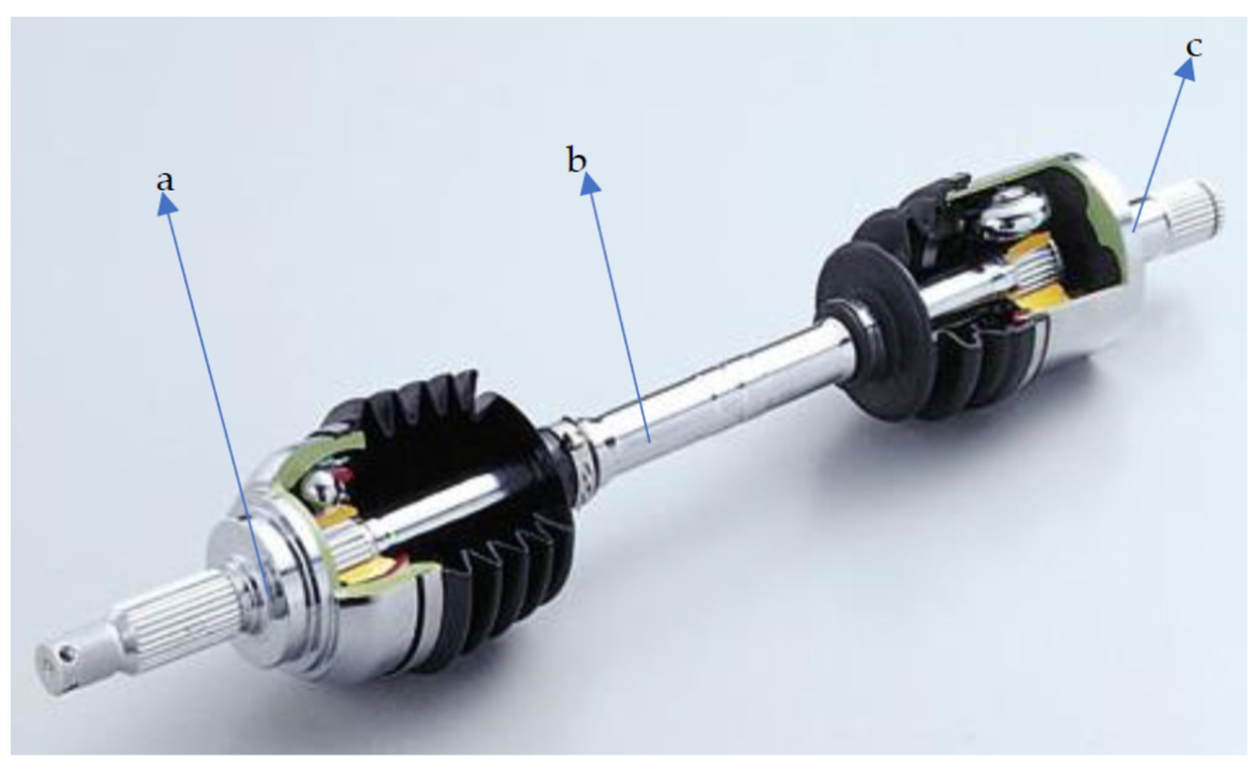
Looking inside the ADE, this kind of transmission, illustrated in Figure 2, has as its basic components (a) the AD’s global bowl, (b) the AD’s axis, and (c) the AD’s tulip. The TTJ’s (tulip–tripod joint-link) components are presented in Figure 3A, having the following parts:
  • the AD–MA (automotive’s driveshaft-middle ax),
  • the tripod linked with tulip and assembled using splines on the middle ax,
  • the tulip’s bell (TB),
  • the tulip ax (TA), assembled with splines in the geared box.
Figure 3B details the BIRJ’s (bowl–inner race joint-link) components. It shows the following components:
  • the AD–MA,
  • the inner race (IR) assembled with splines on the AD–MA,
  • the BB (bowl’s bell) linked with IR through balls,
  • the BA (bowl’s ax) linked to the SW (steering wheel) with splines.

2. The Analysis of DMADFTV

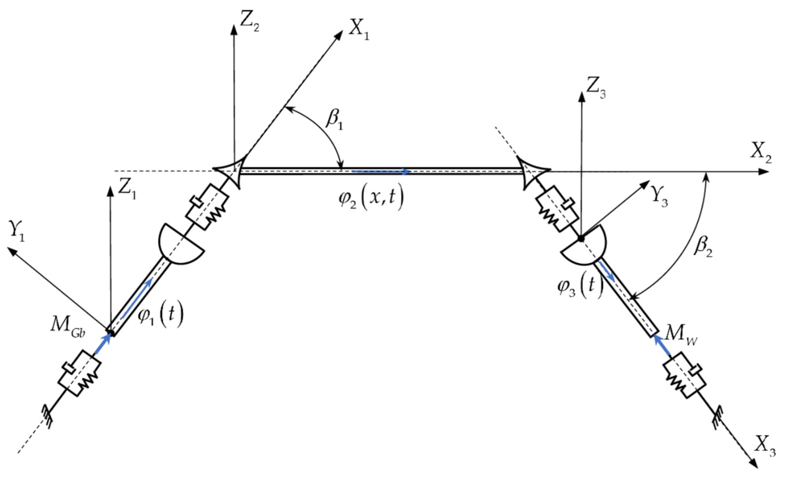
Figure 4 shows a simplified picture of the AD, where each AD’s element has attached a Cartesian reference system such as
X 1 Y 1 Z 1 attached to the GT (global tulip: TB and TA), having a rigid rotation with φ 1 around axis X 1 ,
X 2 Y 2 Z 2 attached to the MA, having a rigid rotation with φ 2 around axis X 2 ,
X 3 Y 3 Z 3 attached to the GB (global bowl: BB and BA), having a rigid rotation with φ 3 around axis X 3 , while β 1 is the angle between the longitudinal directions of the GT and the MA regarding the axis Z 1 , β 1 0 o , 15 o , and β 2 is the angle between the longitudinal directions of the GB and the MA regarding the axis Z 3 , β 2 0 o , 47 o . The angle β 1 between the longitudinal directions of the GT and the MA regarding the axis Z 1 , is given by the internal length of the trucks inside the TB, the external diameter of the MA, and the internal diameter of the TB (see Figure 5a), conforming to the designer calculus [27] (pp. 214–230). The angle β 2 between the longitudinal directions of the GB and the MA regarding the axis Z 3 is given by the internal length of the trucks inside the IR, the external diameter of the MA, and the internal diameter of the BB (see Figure 5b), conforming to the designer calculus [27] (pp. 153–208).
An AD is a multibody driveline transmission from the automotive geared box to the wheel with the geometrical details presented in Figure 5.
To determine the differential equations of the ADFTV based on the variational approach of Hamilton’s principle (VAHP), it is mandatory to realize the reduction of the AIMM (axial inertial mass moment) and the AIGM (axial inertial geometric moment) for the GT and the GB to the longitudinal axis of the MA, respectively X 2 , as illustrated in Figure 5. The AIMM and the AIGM of the GT and the GB consider the angles β 1 and β 2 as well as the specific geometry dimensions of each GT’s components: TB, TA reduced in the tripod’s CM (center mass); and GB’s components: BB, BA reduced in the inner race’s CM, as expressed by the Equations (A1)–(A4) in Appendix A. In Appendix A, Equation (A5) expressed the AIMM and the AIGM for the AD’s MA, while Equation (A6) expressed the stiffnesses and the dampings for the GT and the GB.
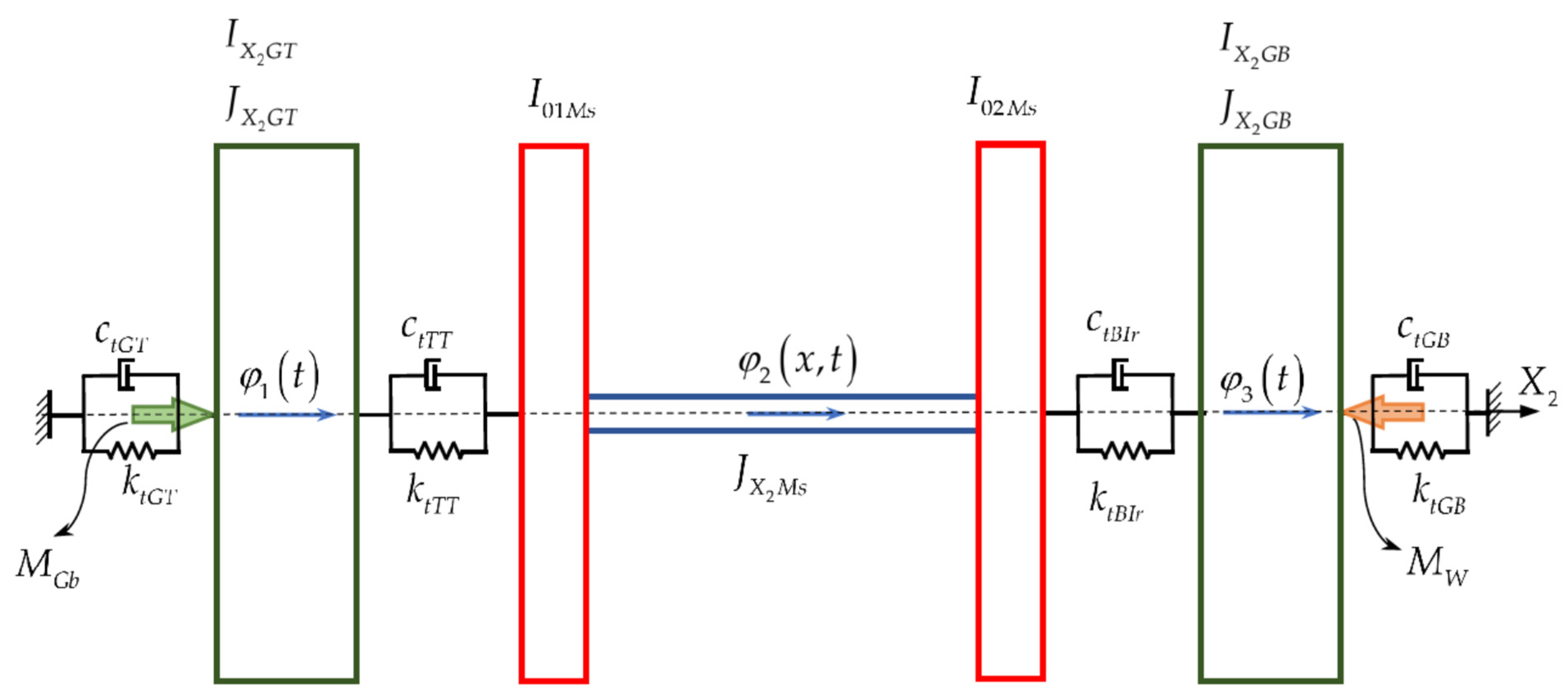
Figure 6 illustrates the DMADFTV (dynamic model of the ADFTV).
The DMADFTV comprises the following elements: the GT, the MA, and the GB, the GT being linked in torsion with the MA through TTJ–CVJ while the GB is linked in torsion with the MA through BIRJ–CVJ. The geared box injects in the AD a moment produced by the internal combustion engine, yielding [3] (p. 361)
M G b = M ¯ e 1 + χ e cos n Ω e t , n N , Ω e = π n e 30 ,
where χ e is the engine moment nonuniformity, having values 0.10–0.12 [3] (p. 363), M ¯ e is the moment’s amplitude, and n e is the engine crankshaft rpm. The moment induced at the wheel is a moderately impulsive kind and has the expression
M w = M H 1 + q 3 t q 1 e q 2 t ,
where M H is the moment of adhesion [27] (p. 130), where q i , i = 1 , 3 ¯ , q 1 q 2 , q 3 1.1 are experimental constants depending on the shock applied to the wheel by the excitation [28].

3. The Equations of ADFTV and the Mathematical Solutions of FOAM

For the DMADFTV illustrated in Figure 6, based on the VAHP [29] (pp. 272–295) results,
δ t 1 t 2 Π T W d t = 0 ,
where Π is strain energy of the DMADFTV that includes the springs and the dampers, as presented in Appendix A [29] (p. 274), [30] (pp. 610–613); T is the kinetic energy of the DMADFTV [29] (p. 274), [30] (p. 719); and W is the work performed by the external torques. In Appendix B, the significance of the terms is shown in [1]. It becomes evident that the MA is a fixed–fixed uniform beam linked in spinning to the TTJ at x = 0 and at the BIRJ at x = L M s and, therefore, φ 2 x , t has the expression presented in Appendix B (see ([30] (p. 720)), where φ 2 n is the amplitude, Θ 1 n and Θ 2 n are the phase angles for the general solution φ 2 ( x , t ) and ω n is the free natural frequency of torsion vibrations of the midshaft. After mathematical calculus yielding the ADFTV’s equations,
φ ¨ 1 + 2 ζ Ω ¯ 1 1 + a 1 cos 2 φ 1 1 + a 2 cos 2 φ 1 1 + χ G T n cos 2 φ 1 φ ˙ 1 + Ω ¯ 1 2 1 + a 1 cos 2 φ 1 1 + a 2 cos 2 φ 1 1 + χ G T n cos 2 φ 1 φ 1 = = M ¯ e I ¯ X 2 G T 1 + χ e cos ( n Ω e t ) 1 + χ G T n cos 2 φ 1 1 3 A T T r sin 3 φ 1 + + n Φ 2 n I 01 M s I ¯ X 2 G T ω n 2 cos Θ 1 n + G J X 2 M s I ¯ X 2 G T ω n c sin Θ 1 n cos ω n t Θ 2 n 1 + χ G T n cos 2 φ 1 , n = 1 , 2 , 3 , ,
φ ¨ 3 + 2 ζ Ω ¯ 3 1 + a 3 cos 2 φ 3 1 + a 4 cos 2 φ 3 1 + χ G B n cos 2 φ 3 φ ˙ 3 + Ω ¯ 3 2 1 + a 3 cos 2 φ 3 1 + a 4 cos 2 φ 3 1 + χ G B n cos 2 φ 3 φ 3 = = M H I ¯ X 2 G B 1 + q 3 t q 1 e q 2 t 1 + χ G B n cos 2 φ 3 1 3 A B I r sin 3 φ 3 + + n 1 n Φ 2 n I 02 M s I ¯ X 2 G B ω n 2 cos Θ 1 n + G J X 2 M s I ¯ X 2 G B ω n c sin Θ 1 n cos ω n t Θ 2 n 1 + χ G B n cos 2 φ 3 , n = 1 , 2 , 3 , ,
where I ¯ X 2 G T is the GT’s AIMM concerning the axis X2 for β 1 = 0 o , χ G T n is the GT nonuniformity (as in Appendix B), I ¯ X 2 G B is the GB’s AIMM concerning the axis X2 for β 2 = 0 o , χ G B n is the GB nonuniformity (as in Appendix B), and Ω ¯ 1 and Ω ¯ 3 are the circular eigenfrequencies in torsion of the GT and GB as functions of β 1 , β 2 , having the mathematical expressions
Ω ¯ 1 = c L T 1 J X 2 A T ρ L A T I ¯ X 2 G T 1 + L A T L T 2 I ¯ X 2 G T J X 2 A T ρ L A T 1 1 / 2 , Ω ¯ 3 = c L B 1 J X 2 A B ρ L A B I ¯ X 2 G B 1 + L A B L B 2 I ¯ X 2 G B J X 2 A B ρ L A B 1 1 / 2 .
For the dynamic instability analysis for ADFTV, different approaches can be used, such as the harmonic balance method (HBM), asymptotic method (AM) [31] (pp. 299–393), and the method of multiple scales (MMS) [32] (pp. 424–427). The HBM is very efficient but allows only the computation of the stationary amplitude of vibrations; the AM permits the calculation of the amplitude and phase angle for both stationary and nonstationary oscillations, while MMS raises computational difficulties due to zeroing the secular term and supplementary analysis for the detuning parameter [31] (pp. 424–427). For the above reasons, the present work uses the asymptotic method approach (AMA) for the solutions of Equations (4) and (5). The use of first-order approximation of AM makes the investigation of dynamic instability of ADFTV in both stationary and nonstationary torsional vibrations in the APPR possible. A small positive parameter must be introduced for both stationary and nonstationary torsional vibrations; the slowing time τ = ε t , ε being a positive small number, as mentioned in [30] (p. 299). These equations must be modified to apply AM before raising τ in Equations (4) and (5). For the AM’s first-order approximation (FOAM), the last terms in Equations (4) and (5) are neglected because the excitation frequency in APPR for GT and the GB is not in the range of free natural frequencies for torsional vibrations of the midshaft. The development gives the approximations used in the mathematical procedure of FOAM in Taylor’s series of the following functions:
1 + a 1 cos 2 φ 1 1 + a 2 cos 2 φ 1 1 + χ G T n cos 2 φ 1 1 + 2 μ 1 cos 2 φ 1 μ 1 1 + α 1 α 2 , M ¯ e I ¯ X 2 G T 1 + χ e cos ( n Ω e t ) 1 + χ G T n cos 2 φ 1 1 3 A T T r sin 3 φ 1 Γ 1 φ 1 3 Γ 1 = 9.1125 A T T r χ G T n M ¯ e I ¯ X 2 G T ,
1 + a 3 cos 2 φ 3 1 + a 4 cos 2 φ 3 1 + χ G B n cos 2 φ 3 1 + 2 μ 3 cos 2 φ 3 μ 3 1 + α 3 α 4 , M H I ¯ X 2 G B 1 + q 3 t q 1 e q 2 t 1 + χ G B n cos 2 φ 3 1 3 A B I r sin 3 φ 3 = Γ 3 φ 3 3 + Γ 5 φ 3 5 , Γ 3 = 9.1125 A B I r χ G B n M H I ¯ X 2 G B , Γ 5 = 18.225 A B I r χ G B n M H I ¯ X 2 G B ,
whose coefficients α i , i = 1 , 2 , 3 , 4 are presented in Appendix B. In Equations (7) and (8), the terms μ 1 = f 1 χ G T n , J X 2 A T , ρ , L A T , L A T L T 2 , I ¯ X 2 G T , μ 3 = f 3 χ G B n , J X 2 A B , ρ , L A B , L A B L B 2 , I ¯ X 2 G B express the internal parametric excitations of GT and GB (see Equations (A13)–(A16) in Appendix B), while the terms Γ 1 = g 1 A T T r χ G T n , M ¯ e I ¯ X 2 G T , Γ 3 = g 3 A B I r χ G B n , M H I ¯ X 2 G B , Γ 5 = g 5 A B I r χ G B n , M H I ¯ X 2 G B express the external cubic and quintic external excitations for GT and GB (see Equations (2) and (A10) in Appendix B). The functions f i , i = 1 , 2 and g i , i = 1 , 2 , 3 have the variables mentioned above represent the physical sources of these internal and external excitations. Injecting the relations (7) in Equation (4) and repeating the same manipulation by injecting the relations (8) in Equation (5) yields
φ ¨ 1 + + Ω ¯ 1 2 φ 1 = 2 ζ Ω ¯ 1 ( 1 + α 1 + α 2 cos 2 φ 1 ) φ ˙ 1 Ω ¯ 1 2 ( 2 α 1 + α 1 2 + 2 μ 1 cos 2 φ 1 ) φ 1 + Γ 1 φ 1 3 ,
φ ¨ 3 + + Ω ¯ 3 2 φ 3 = 2 ζ Ω ¯ 3 ( 1 + α 3 + α 4 cos 2 φ 1 ) φ ˙ 3 Ω ¯ 3 2 ( 2 α 3 + α 3 2 + 2 μ 3 cos 2 φ 3 ) φ 3 + Γ 3 φ 3 3 + Γ 5 φ 3 5 .
Equations (9) and (10) represent the FTV of the GT and GB in APPR that include the following effects: the kinematic and geometric nonuniformity of quasi-homokinetic tripod’s joints, the nonuniformity of AIGM and AIMM for the elements of AD and the nonuniformity of external harmonic excitations of the engine, and the reaction torque induced by the wheel. The excitation frequencies η 1 , η 3 of the GT and the GB of AD in the APPR must be defined by the expressions
η 3 = d Θ 3 d t = 2 d φ 3 d t 2 Ω ¯ 3 , η 1 = d Θ 1 d t = 2 d φ 1 d t 2 Ω ¯ 1 ,
and introducing the slowing time by imposing the condition that all the coefficients in Equations (9) and (10) are small yields
d Θ 1 d t = η 1 ( τ ) , Θ 1 = 2 φ 1 , ξ = ε ξ , μ 1 = ε μ 1 , α 1 = ε α 1 , α 2 = ε α 2 , Γ 1 = ε Γ 1 ,
d Θ 3 d t = η 3 ( τ ) , Θ 3 = 2 φ 3 , ξ = ε ξ , μ 3 = ε μ 3 , α 3 = ε α 3 , α 4 = ε α 4 , Γ 3 = ε Γ 3 , Γ 5 = ε Γ 5 .
Neglecting the terms that contain ε 2 after injecting relations (12), (13) in Equations (9) and (10) results in
φ ¨ 1 + + Ω ¯ 1 2 φ 1 = ε 2 ζ Ω ¯ 1 φ ˙ 1 Ω ¯ 1 2 ( 2 α 1 + 2 μ 1 cos 2 φ 1 ) φ 1 + Γ 1 φ 1 3 ,
φ ¨ 3 + + Ω ¯ 3 2 φ 3 = ε 2 ζ Ω ¯ 3 φ ˙ 3 Ω ¯ 3 2 ( 2 α 3 + 2 μ 3 cos 2 φ 3 ) φ 3 + Γ 3 φ 3 3 + Γ 5 φ 3 5 .
Analyzing Equations (14) and (15), it can be remarked that the global terms on the right-hand side (RHS) are excitations, while in contrast, the left-hand side (LHS) global parts are linear oscillators. For FOAM, there were meant to be analytical solutions for Equations (14) and (15), having the expressions
φ 1 = Φ 1 cos 1 2 Θ 1 + Ψ 1 , φ 3 = Φ 3 cos 1 2 Θ 3 + Ψ 3 ,
where Φ 1 , Φ 3 are the amplitudes and Ψ 1 , Ψ 3 are the phase angles for global tulip and global bowl, given by the Equations
d Φ 1 d t = ε D 1 τ , Φ 1 , Ψ 1 d Ψ 1 d t = Ω ¯ 1 1 2 η 1 τ + ε E 1 τ , Φ 1 , Ψ 1 , d Φ 3 d t = ε D 3 τ , Φ 3 , Ψ 3 d Ψ 3 d t = Ω ¯ 3 1 2 η 3 τ + ε E 3 τ , Φ 3 , Ψ 3 .
Differentiating concerning the time, the system of Equation (17) yields
d 2 Φ 1 d t 2 = ε D 1 Ψ 1 Ω ¯ 1 1 2 η 1 + ε 2 …………………… d 2 Ψ 1 d t 2 = ε 1 2 η 1 τ + E 1 Ψ 1 Ω ¯ 1 1 2 η 1 + ε 2 , d 2 Φ 3 d t 2 = ε D 3 Ψ 3 Ω ¯ 3 1 2 η 3 + ε 2 …………………… d 2 Ψ 3 d t 2 = ε 1 2 η 3 τ + E 3 Ψ 3 Ω ¯ 3 1 2 η 3 + ε 2 .
Using the first system of equations expressed in Equations (17) and (18) and the supposed solution (16) in Equation (14), balancing the coefficients of the mathematical expressions ε cos 1 2 Φ 1 + Ψ 1 , ε sin 1 2 Φ 1 + Ψ 1 from the LHS with those from the RHS, and neglecting the terms containing sin ( k 1 2 Φ 1 + Ψ 1 ) , cos ( k 1 2 Φ 1 + Ψ 1 ) , k 1 = 2 , 3 , 4 results in the differential system of equations (DSOE) for the GT:
D 1 Ψ 1 Ω ¯ 1 1 2 η 1 2 Φ 1 Ω ¯ 1 E 1 = μ 1 Φ 1 Ω ¯ 1 2 cos 2 Ψ 1 3 4 Γ 1 Φ 1 3 Φ 1 E 1 Ψ 1 Ω ¯ 1 1 2 η 1 + 2 Ω ¯ 1 D 1 = μ 1 Φ 1 Ω ¯ 1 2 sin 2 Ψ 1 2 ξ Ω ¯ 1 2 Φ 1 ,
and proceeding with the same mathematical manipulations in Equation (15) by using the second system of equations expressed in Equations (17) and (18), and the supposed solution (16), balancing the coefficients of the mathematical expressions ε cos 1 2 Φ 3 + Ψ 3 , ε sin 1 2 Φ 3 + Ψ 3 from the LHS with those from the RHS, and neglecting the terms containing sin ( k 2 2 Φ 3 + Ψ 3 ) , cos ( k 2 2 Φ 3 + Ψ 3 ) , k 2 = 2 , 3 , 4 , 5 results in the differential system of equations (DSOE) for the GB:
D 3 Ψ 3 Ω ¯ 3 1 2 η 3 2 Φ 3 Ω ¯ 3 E 3 = μ 3 Φ 3 Ω ¯ 3 2 cos 2 Ψ 3 3 4 Γ 3 Φ 1 3 5 8 Γ 5 Φ 3 5 Φ 1 E 3 Ψ 3 Ω ¯ 3 1 2 η 3 + 2 Ω ¯ 3 D 3 = μ 3 Φ 3 Ω ¯ 3 2 sin 2 Ψ 3 2 ξ Ω ¯ 3 2 Φ 3 ,
which yields the solutions of DSOE (19) for the GT and (20) for the GB:
D 1 = μ 1 Ω ¯ 1 2 Φ 1 η 1 sin 2 Ψ 1 ξ Ω ¯ 1 Φ 1 E 1 = μ 1 Ω ¯ 1 2 η 1 cos 2 Ψ 1 + 3 8 Γ 1 Φ 1 2 Ω 1 , D 3 = μ 3 Ω ¯ 3 2 Φ 3 η 3 sin 2 Ψ 3 ξ Ω ¯ 3 Φ 3 E 3 = μ 3 Ω ¯ 3 2 η 3 cos 2 Ψ 3 + 3 8 Γ 3 Φ 3 2 Ω 3 + 5 16 Γ 5 Φ 3 4 Ω 3 .
Using the system of Equation (21) in the DSOE (17) and considering all the characteristics of the systems in real-time values yields the DSOEs of the analytical amplitudes and the phases angles of FTV for GT and GB in the APPR for each element:
d Φ 1 d t = μ 1 Ω ¯ 1 2 Φ 1 η 1 sin 2 Ψ 1 ξ Ω ¯ 1 Φ 1 d Ψ 1 d t = Ω ¯ 1 1 2 η 1 μ 1 Ω ¯ 1 2 η 1 cos 2 Ψ 1 + 3 8 Γ 1 Φ 1 2 Ω 1 , d Φ 3 d t = μ 3 Ω ¯ 3 2 Φ 3 η 3 sin 2 Ψ 3 ξ Ω ¯ 3 Φ 3 d Ψ 3 d t = Ω ¯ 3 1 2 η 3 μ 3 Ω ¯ 3 2 η 3 cos 2 Ψ 3 + 3 8 Γ 3 Φ 3 2 Ω 3 + 5 16 Γ 5 Φ 3 4 Ω 3 .
The investigation of dynamic instability for the stationary FTV of AD consists of computing the dynamic instability boundary frontiers (DIBF) of GT and GB in the APPR. The stationary dynamic behavior of FTV for the GT and the GB is characterized by zeroing d Φ 1 d t , d Ψ 1 d t , d Φ 3 d t , d Ψ 3 d t in DSOE (22) and expressing the trigonometric identity sin 2 Ψ i + cos 2 Ψ i = 1 , i = 1 , 3 . This yields, for global tulip and global bowl,
η 1 Ω 1 2 ξ 2 + 1 η 1 2 Ω 1 2 μ 1 2 = 0 , η 3 Ω 3 2 ξ 2 + 1 η 3 2 Ω 3 2 μ 3 2 = 0 ,
in the spaces η 1 , ξ , μ 1 , η 3 , ξ , μ 3 , that is, the space (excitation frequency, damping ratio, excitation parameter).
As can be remarked for Equation (23), the instability frontiers for stationary FTV (SFTV) of GT and GB do not contain the amplitudes Φ 1 , Φ 3 because the frontiers of instability are defined as the limits for which the amplitudes may initiate, and the amplitudes must be put to zero in APPR. For the dynamic instability analysis of nonstationary FTV (NFTV), the DSOE (22) was used to compute the spectral amplitudes (SA) and the spectral velocity amplitudes (SVA) of GT and GB in transition through APPR. For dynamic instability analysis in transition through APPR, the sweep of rate (SOR) of the excitation frequencies for global tulip and global bowl were considered to have logarithmic variations, yielding thus the equations
η 1 = η ¯ 1 κ 1 t ( 1 + n ) , κ 1 1 , η 3 = η ¯ 3 κ 3 t ( 1 + n ) , κ 3 1 .
where η ¯ 1 , η ¯ 3 are the starting frequencies of the logarithmic frequency balayage (LFB) for global tulip and global bowl, and n is the frequency’s SOR. To integrate the DSOE (22) numerically, MATLAB software (version R 2017) was developed based on function ode 45 (Runge–Kutta integration method of fifth order). Thus, the SA and SVA were computed, making the determination of the graph’s velocity amplitude versus amplitude for the GT and GB possible. The graph’s velocity amplitude versus amplitude represents the phase portrait of NFTV for GT and GB, which is the detection method of possible chaotic dynamic behavior.

4. Results and Discussion

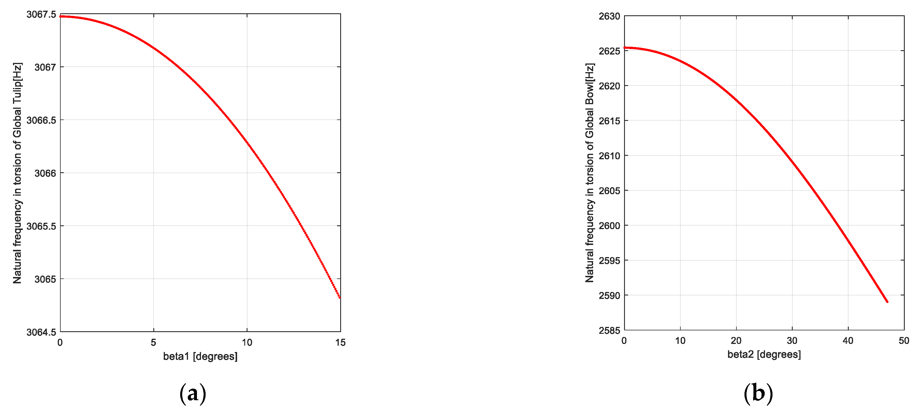
Figure 7 illustrates the variation of the AD’s GT and GB natural frequencies based on Equation (6).
Comparing the obtained results with the published ones in [5] (pp. 119–139), the conclusion is clear that the DMADFTV-computed circular eigenfrequencies agree with the data in the literature. The potential sources of discrepancies between the theoretical predictions and experimental measurements mentioned before might be manufacturing tolerances, material inconsistencies, or assembly imperfections. These practical technical aspects could explain the differences between the simulated results and the experimental data published in [5] (pp. 119–139), which are less than 3% for the eigenfrequency of the GT and less than 4% for the GB. The free natural frequencies of the GT and the GB that are computed based on Equation (6) are not sensitive to the logarithmic decrement ξ that participates in Equations (14) and (15) in the RHS as an attenuation term of the excitations. The nonuniformities of the AIMM and AIGM for the GB and the GT are expressed in the terms χ n B , χ n T (see Equations (A1)–(A3) in Appendix A) and χ G B n , χ G T n (see Equations (A13) and (A14) in Appendix B), and the angles β 1 , β 2 influence the free eigenfrequencies computed with Equation (6).
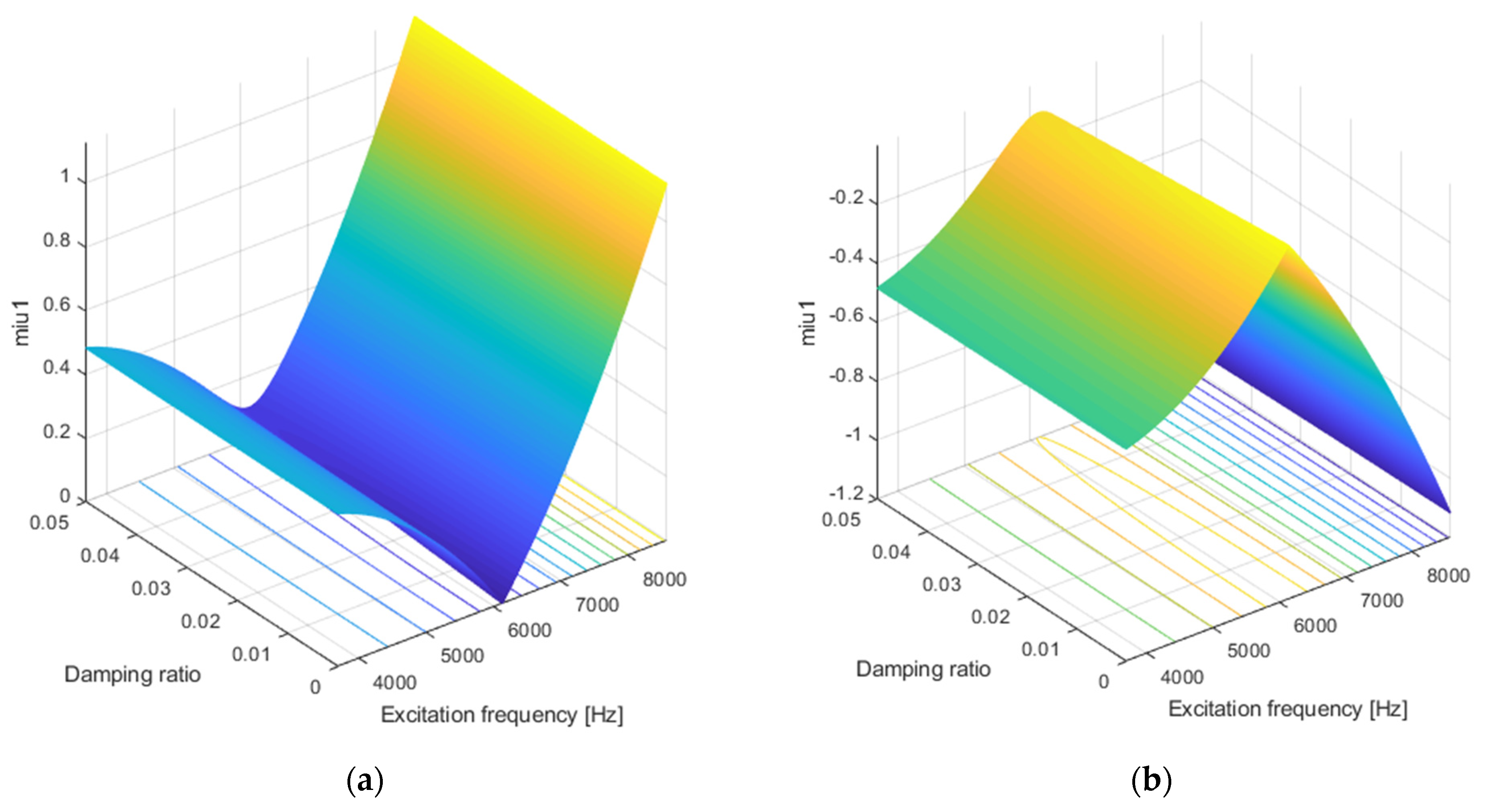
Based on Equation (23), MATLAB software was developed to calculate the dynamic instability boundary frontiers (DIBF) for the stationary GT’s FTV and GB’s FTV; the graphs are presented in Figure 8 and Figure 9.
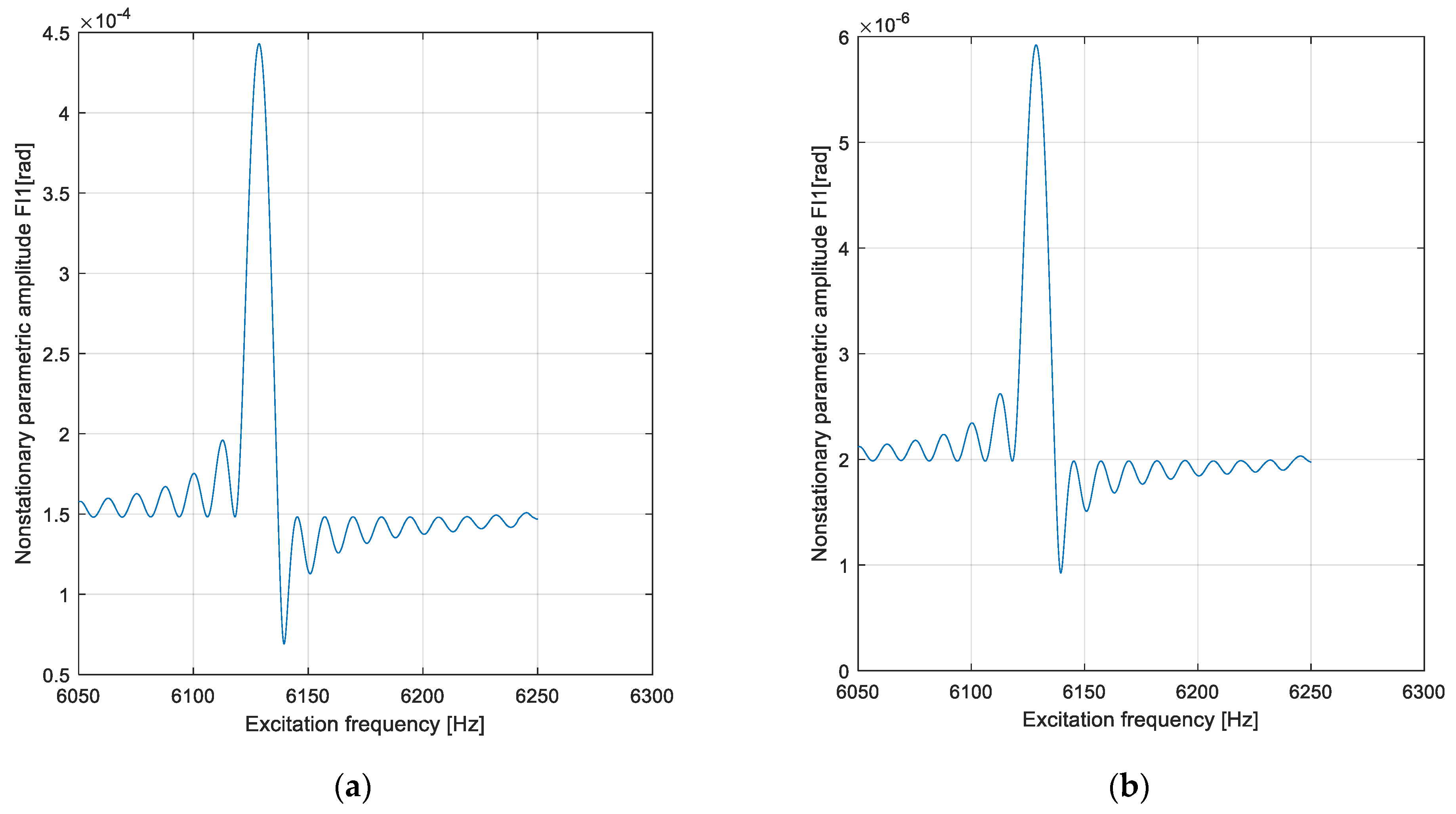
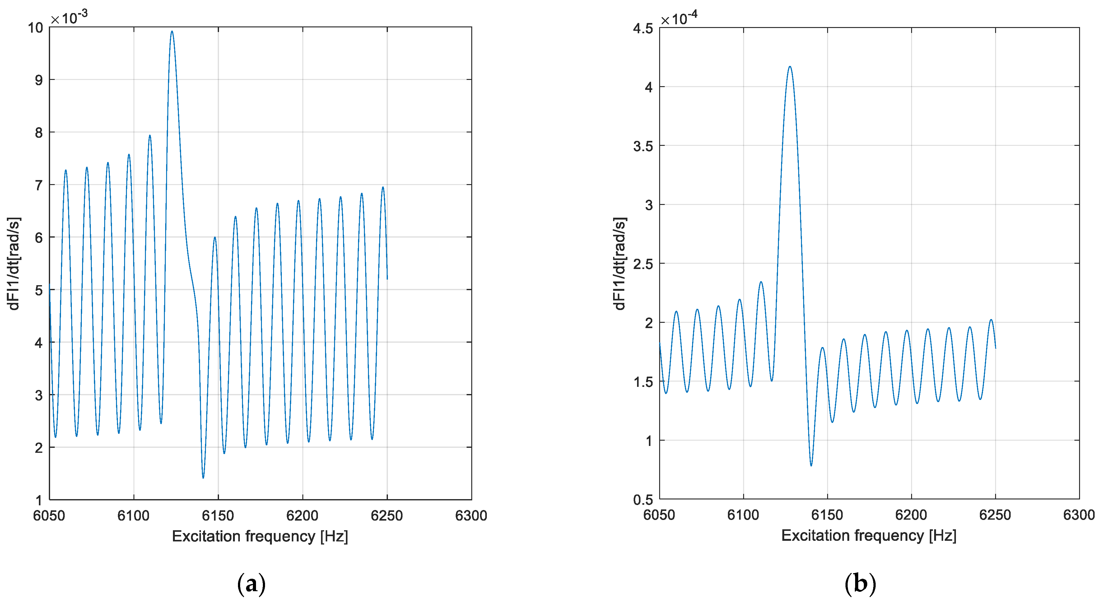
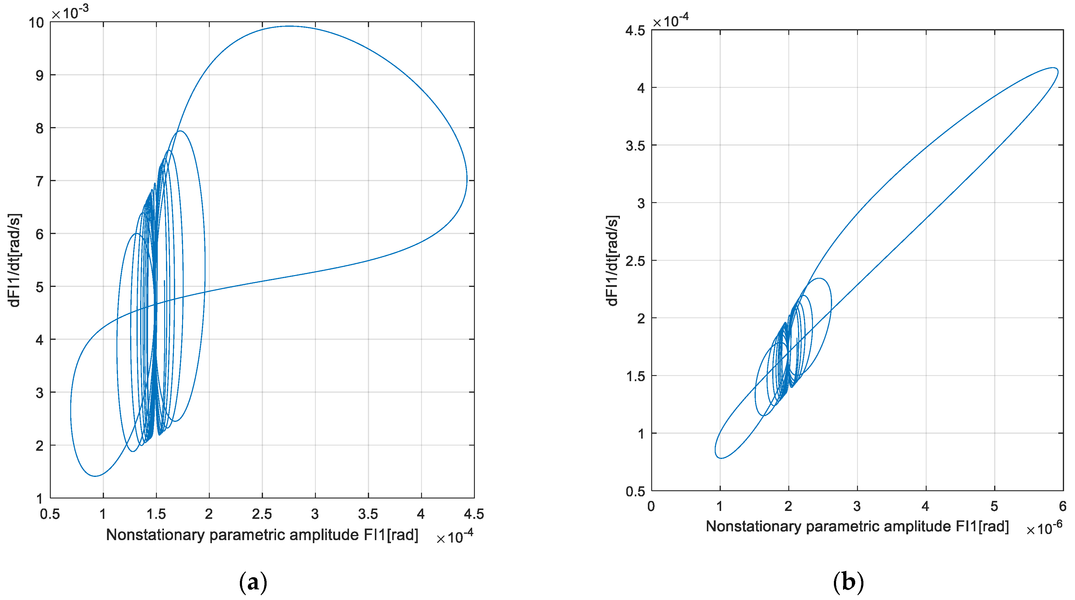
Analyzing the graphs presented in Figure 8 and Figure 9, it can be remarked that the folded surface of the DIBF manifests symmetry concerning the plane (excitation frequency, damping ratio), having the same manifestation as for the global tulip and the global bowl. Because the damping ratio ξ is an isotropic physical property of the material, analyzing the needed limit values to obtain DIBF for the global tulip and the global bowl, the condition is that the steel composition must satisfy the condition ξ 0.0044 if it is used for the fabrication of the driveline of the same steel. It can also be remarked that the folded surfaces illustrated in Figure 8 and Figure 9 close, between their two branches, the instability volume in the space η 1 , ξ , μ 1 for the global tulip and the space η 3 , ξ , μ 3 for the global bowl. Figure 10, Figure 11 and Figure 12 illustrate the graphs for investigating the dynamic instability of NFTV for the global tulip in transition through APPR η 1 6131.6   H z , considering the worst case for the global tulip β 1 = 15 o , μ 1 = 0.1001 , Ω ¯ 1 = 19263   r a d / s , χ G T n = 0.0073 , Γ 1 = 1.9298 10 4   s 2 r a d 2 , n = 0.000008 [octaves/min], and the damping ratio ξ = 0.0016…0.0043 . MATLAB software was developed based on DSOE (22) for NFTV of the global tulip to calculate Φ 1 η 1 , d Φ 1 d t η 1 .
For the graphs illustrated in Figure 10, Figure 11 and Figure 12, the excitation frequency has a logarithmic balayage for NFTV of the GT in transition through APPR. In contrast, the characteristics of internal and external excitations μ 1 , χ G T n , Γ 1 are constants. In Figure 10 and Figure 11, it is remarked that the nonstationary SA and SVA Φ 1 η 1 ,   d Φ 1 d t η 1 for NFTV of the GT manifest the “beatings” and a rapid decrease of the extreme values with the damping’s increases in the range ( 1.6……4.3 ) × 10 3 . The greatest value of the nonstationary SA and SVA for NFTV of the GT is reached when η 1 = 6136   H z .
Figure 12 shows that the “look” is similar to the strange attractor’s representations. A chaos detection method was developed for AD by employing the FOAM for the GT’s NFTV; a chaos detection method was developed for AD’s NFTV.
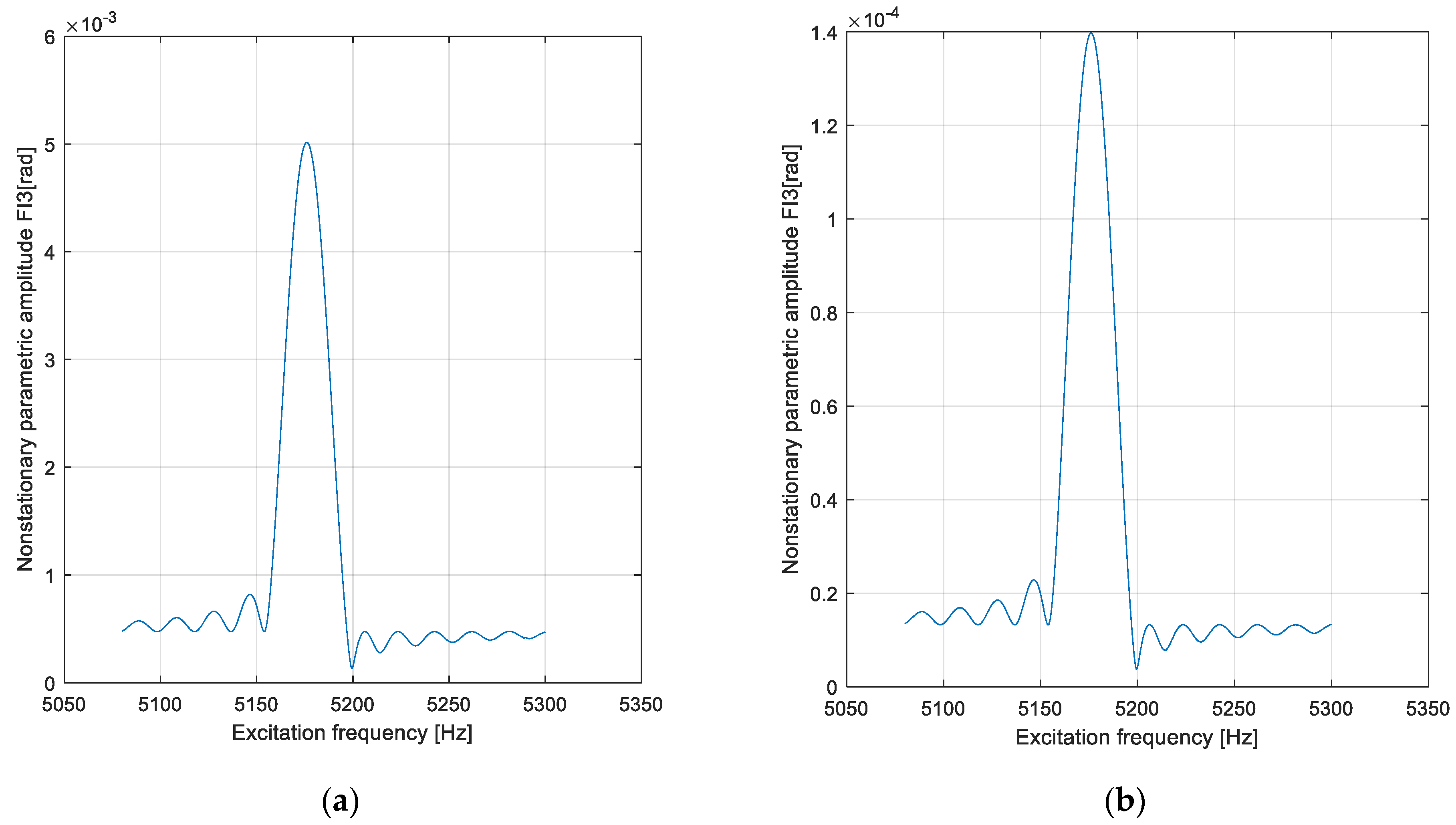
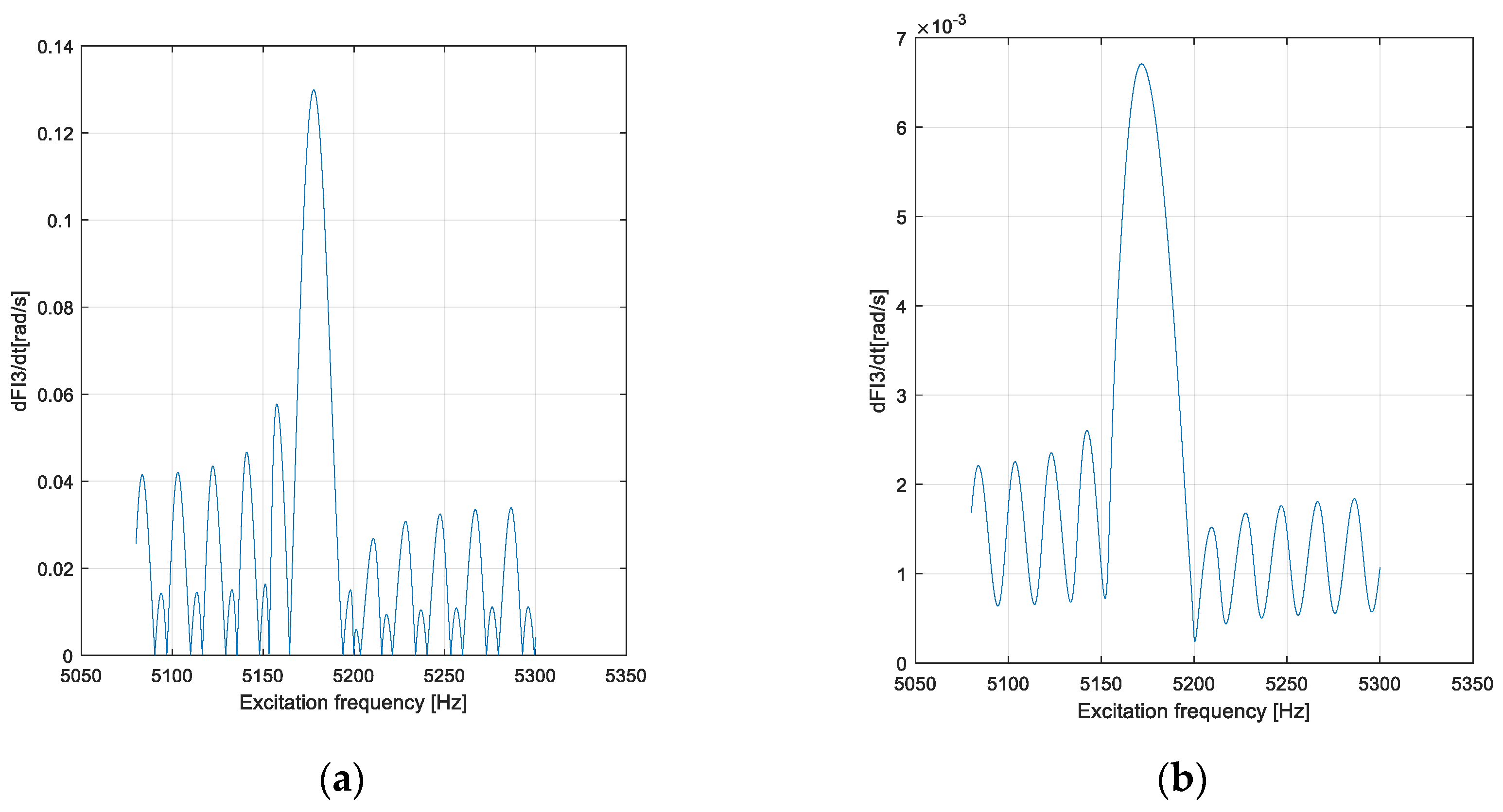
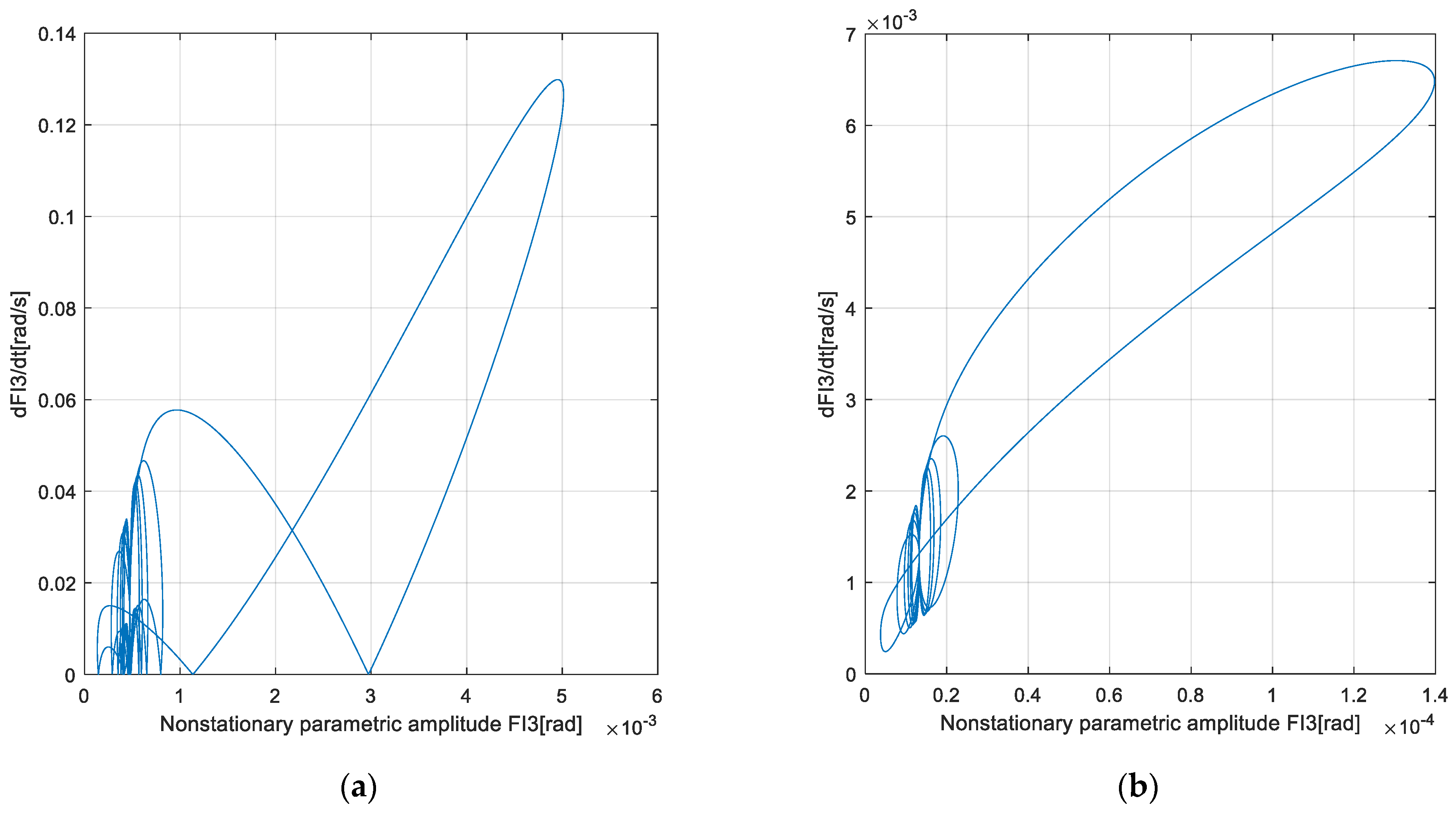
For the graphs illustrated in Figure 13, Figure 14 and Figure 15, the excitation frequency has a logarithmic balayage for the GB’s NFTV in transition through APPR η 3 5180   H z , considering the worst case for the GB β 2 = 47 0 ,   μ 3 = 0.0065 ,   Ω ¯ 3 = 16273.5   r a d / s ,   χ G B n = 0.0492 ,   Γ 3 = 9.9638 × 10 4   s 2 r a d 2 ,   Γ 5 = 1.9928 × 10 5   s 2 r a d 4 ,   n = 0.00001 [octaves/min], and the damping ratio ξ = 0.0016…0.006 . MATLAB software was developed based on DSOE (22) for nonstationary NFTV of the GB to calculate Φ 3 η 3 , d Φ 3 d t η 3 .
For the graphs illustrated in Figure 13, Figure 14 and Figure 15, the excitation frequency has a logarithmic balayage for NFTV of the GB in transition through APRR. In contrast, the characteristics of internal and external excitations μ 3 , χ G B n , Γ 3 , Γ 5 are constants. In Figure 13 and Figure 14, it is remarked that the nonstationary SA and SVA Φ 3 η 3 , d Φ 3 d t η 3 for NFTV of GB manifest the “beatings” and a rapid decrease of the extreme values with the damping’s increases in the range ( 1.6……6.0 ) × 10 3 . The greatest value of the nonstationary SA and SVA for NFTV of the GB is reached when η 3 = 5180   H z .
It is remarked that the “pictures” in Figure 15 are like those specific to a strange attractor. In this way, the aim of using FOAM for NFTV of the GB was reached, FOAM being thus a detection method for chaos manifestation of NFTV for the elements of AD. Comparing Figure 10, Figure 11 and Figure 12 with Figure 13, Figure 14 and Figure 15 shows the same trend for the global tulip and the global bowl regarding the NFTV of AD’s elements in transition through APPR. A possible chaotic dynamic behavior for these elements was detected using the FOAM to investigate NFTV for AD’s elements.

5. Conclusions

This paper deals with the dynamic instability analysis for the AD in transition through APPR. To achieve its goals, first, the study modified an existent model for ADFTV by designing a DMADFTV of an AD that includes the nonuniformity of AIGM, the nonuniformity of AIMM, the quasi-homokinetic CVJ joints, and the external harmonic excitations induced by the gearbox and the reactive torque generated by the wheel. The specific assumptions made when reducing the AIMM and the AIGM to the longitudinal axis of the GB and GT do not impact the generality of the DMADFTV. Based on this DMADFTV, the stationary dynamic instability of the ADE (GT, GB) was investigated by computing the instability frontiers using FOAM. Using FOAM with the second-order differential Equation (9), expressing the GT’s FTV, and Equation (10), expressing the GB’s FTV, results in the nonstationary amplitudes and nonstationary phase angles in the APPR given by the DSOE (22). Based on the LFB with a specific SOR, the phase portraits NSVA–NSA for the GT and GB were computed, and this mathematical approach represented the detection method of chaotic AD’s FTV. Steinwede demonstrated in [4], using sophisticated experiments, that the chaotic consequences are the cracks, the micro-cracks, and the pitting that were detected on the tripod’s TTJ, the balls’s BIRJ, and the IR’s BIRJ; this is mandatory for the chaos manifestation control in the design of AD’s components. The FOAM used in this study represents only a method of detecting the possible chaotic manifestation of ADFTV. The confirmation of the chaotic manifestation of ADFTV is given only by a study of the chaotic manifestation based on an investigation of Lyapunov’s or Jacobi’s stability.
In future research, the authors hope to develop the use of Jacobi’s stability analysis and the KCC theory, as mentioned in [20,21,22,23], to control the chaotic manifestation of GT’s FTV and GB’s FTV in transition through other possible resonances such as internal, superharmonic, combination, and subharmonic, as mentioned by Nayfeh in [32].

Author Contributions

Conceptualization, M.B.; methodology, M.B.; software, M.B. and O.V.; validation, M.B.; formal analysis, M.B.; investigation, M.B.; resources, M.B. and O.V.; data curation, M.B. and O.V.; writing—original draft preparation, M.B.; writing—review and editing, M.B.; visualization, M.B.; supervision, M.B.; project administration, M.B. and O.V. All authors have read and agreed to the published version of the manuscript.

Funding

This research received no external funding.

Institutional Review Board Statement

Not applicable.

Informed Consent Statement

Not applicable.

Data Availability Statement

The original contributions presented in the study are included in the article, further inquiries can be directed to the corresponding author.

Acknowledgments

The authors of this article are thankful to the National University of Science and Technology Politehnica Bucharest for providing a serene environment and facilities for carrying out this research.

Conflicts of Interest

The authors declare no conflicts of interest.

Abbreviation

The List of Mathematical Symbols in Appendix A and Appendix B
a 1 , a 2 variable coefficients in Equation (A13)-Appendix B, and Equations (4) and (7),
a 3 , a 4 variable coefficients in Equation (A14)-Appendix B, and Equations (5) and (8),
c uniform speed of the torsional wave,
c t B I r damping coefficient of the BIRJ in torsion,
c t G B damping coefficient of the GB in torsion,
c t G T damping coefficient of the GT in torsion,
c t T T damping coefficient of the TTJ in torsion,
d A B diameter of the BA,
d A T diameter of the TA,
d C B distance from the BB’s CM to the centroid of the inner race,
d C T distance from the TB’s CM to the centroid of the tripod,
d M s diameter of the middle ax,
k t A B torsional stiffness of the BA,
k t A T torsional stiffness of the TA,
k t B torsional stiffness of the BB,
k t T torsional stiffness of the TB,
k t G B torsional stiffness of the GB,
k t G T torsional stiffness of the GT,
k t B I r torsional stiffness of the BIRJ,
k t T T torsional stiffness of the TTJ,
A B I r non-dimensional coefficient of the ADGN induced by BIRJ’s quasi-isometry mentioned in [2,4],
A T T r non-dimensional coefficient of the ADGN induced by TTJ’s quasi-isometry mentioned in [2,4],
C 1 , C 2 variable coefficients in Equation (A15)-Appendix B,
C 3 , C 4 variable coefficients in Equation (A16)-Appendix B,
Gtransversal elasticity modulus,
I X 2 G B AIMM of the GB,
I X 2 G T AIMM of the GT,
J 1 I r , J 2 I r principal AIGMs of the inner race,
I 01 M s AIMM of the tripod,
I 02 M s AIMM of the inner race,
J X 2 M s AIGM of the uniform middle ax (midshaft) as a bar/tube,
J X 2 A B AIGM of the bowl’s ax,
J X 2 A T AIGM of the tulip’s ax,
J X 2 G B AIGM of the GB,
J X 2 G T AIGM of the GT,
J X 2 B AIGM of the BB,
J X 2 T AIGM of the TB,
J 1 B , J 2 B principal AIGMs of the BB,
J 1 T , J 2 T principal AIGMs of the TB,
J 1 T r , J 2 T r principal AIGMs of the tripod,
J X 2 I r AIGM of the inner race,
J X 2 T r AIGM of the tripod,
L A B length of the BA,
L B length of the BB,
L A T length of the TA,
L I r length of the inner race,
L M s length of the MA,
L T length of the TB,
L T r length of the tripod,
R B I r rayon of the coupling torsion for the link BB–inner race,
R T T r rayon of the coupling torsion for the link TB–tripod,
S B cross-section area of BB,
S T cross-section area of TB,
α 1 , α 2 variable coefficients in Equation (A15)-Appendix B, and Equations (7) and (9),
α 3 , α 4 variable coefficients in Equation (A16)-Appendix B, and Equations (8) and (10),
χ n B AIGM nonuniformity of the BB,
χ n T AIGM’s nonuniformity of the TB,
χ G B n AIMM’s nonuniformity of the GB,
χ G T n AIMM’s nonuniformity of the GT,
ξ logarithmic decrement of the AD’s material,
ρ AD’s material density.
Nomenclature of Acronyms and Abbreviations
ADEautomotive driveshaft’s elements [28],
ADFTVautomotive driveshaft’s forced torsional vibration [1,28],
ADGNautomotive driveshaft’s geometric nonuniformity, in the isometric sense [2,4], mathematically defined by Equation (A11) in Appendix B [4],
ADKNautomotive driveshaft’s kinematic nonuniformity, in the isometric sense [2,4],
ADLautomotive drive line,
AD-MAautomotive driveshaft-middle ax [1,28],
AIGMaxial inertial geometric moment [1],
AIMMaxial inertial mass moment [1],
AMasymptotic method [31],
AMAasymptotic method approach [31],
APPRthe area of principal parametric resonance, mathematically defined by Equation (11), [26] (p. 341), [6,32],
BAbowl’s ax [1,4],
BBbowl’s bell [1,4],
BIRJbowl-inner race joint [1,28],
CMcenter mass,
CVJconstant velocity joint [1,4,28],
DIBFdynamic instability boundary frontiers [26,32],
DOFdegrees of freedom,
DMADFTVthe dynamic model for the automotive driveshaft’s forced torsional vibration,
DSOEdifferential system of equations,
FOAMfirst-order asymptotic method [31],
HBMharmonic balance method [1,31],
ICSMinertial characteristics for the spinning movements [1],
INP-ADisometry nonuniformity properties of AD [2,4],
IRinner race (of the GB) [28],
KCCKosambi–Cartan–Chern theory [20,21,22,23,24,25],
LFBlogarithmic frequency balayage [31,32],
LHSleft-hand side,
MAmiddle ax [1,28],
NAnonlinear amplitude [26,31,32],
NFTVnonstationary forced torsional vibrations [26,31,32],
NPAnonlinear phase angle [26,31,32],
NSAnonstationary spectral amplitude [26,31,32],
NSVAnonstationary spectral velocity amplitude [26,31,32],
RHSright-hand side,
SAspectral amplitude [26,31,32],
SORsweep of rate [26,31],
SUVsport utility vehicle,
SVAspectral velocity amplitude [26,31,32],
SSASix Sigma Approach [12],
SWsteering wheel,
TAtulip’s ax [1,28],
TBtulip’s bell [1,28],
TTJtulip–tripod joint [1,28],
VAHPvariational approach of Hamilton’s principle [29] (pp. 272–295).

Appendix A. Relations of AIGM, AIMM, Stiffness, Damping Coefficients of TA, GT, Tripod, MA, IR, BA, GB, and the Coefficients in the Mathematical Procedure of AM

J X 2 G T = J X 2 T + J X 2 A T , J X 2 T = 0.5 J 1 T + J 2 T 1 + cos 2 β 1 + χ n T cos 2 φ 1 sin 2 β 1 + S T d C T 2 , χ n T = J 1 T J 2 T J 1 T + J 2 T ,
J X 2 A T = π d A T 4 64 1 + cos 2 β 1 + π d A T 2 4 L T + 0.5 L A T 2 , I X 2 G T = J X 2 T ρ L T + J X 2 A T ρ L A T ,
J X 2 G B = J X 2 B + J X 2 A B , J X 2 B = 0.5 J 1 B + J 2 B 1 + cos 2 β 2 + χ n B cos 2 φ 3 sin 2 β 2 + S B d C B 2 , χ n B = J 1 B J 2 B J 1 B + J 2 B ,
J X 2 A B = π d A B 4 64 1 + cos 2 β 2 + π d A B 2 4 L B + 0.5 L A B 2 , I X 2 G B = J X 2 B ρ L B + J X 2 A B ρ L A B ,
I 01 M s = J X 2 T r ρ L T r = J 1 T r + J 2 T r ρ L T r , I 02 M s = J X 2 I r ρ L I r = J 1 I r + J 2 I r ρ L I r , J X 2 M s = π d M s 4 32 , J X 2 M s = π d e M s 4 d i M s 4 32 ,
k t G T = k t A T k t T k t A T + k t T , k t A T = G J X 2 A T L A T , k t T = G J X 2 T L T , c t G T = 2 ξ k t G T I X 2 G T , k t G B = k t A B k t B k t A B + k t B , k t A B = G J X 2 A B L A B , k t B = G J X 2 B L B , c t G B = 2 ξ k t G B I X 2 G B ,

Appendix B. Mathematical Expressions of the Terms and Coefficients in Paragraph 3

Π = 1 2 0 L M s G J X 2 M s φ 2 x 2 d x + + 1 2 c t G T φ 1 2 + c t T T φ 2 0 , t x φ 1 2 + c t B I r φ 3 φ 2 L M s , t x 2 + c t G B φ 3 2 + + 1 2 k t G T φ 1 2 + k t T T φ 2 0 , t φ 1 2 + k t B I r φ 3 φ 2 L M s , t 2 + k t G B φ 3 2 ,
T = 0 L M s 1 2 ρ J X 2 M s φ 2 t 2 d x + 1 2 I X 2 G T φ 1 2 + 1 2 I 01 M s φ 2 0 , t t 2 + + 1 2 I 02 M s φ 2 L M s , t t 2 + 1 2 I X 2 G B φ 3 2 ,
W = 0 L M s M G b Δ ( x ) + M w Δ ( x L M s ) φ 2 ( x , t ) d x = = M G b φ 2 ( 0 , t ) + M w φ 2 ( L M s , t ) ,
A T T r = 0.5 R T T r L M s tan β 1 tan 2 β 1 2 , A B I r = 0.5 R B I r L M s tan β 2 tan 2 β 2 2 ,
φ 2 0 , t = φ 1 t + R T T r 2 L M s tan β 1 tan 2 β 1 2 cos ( 3 φ 1 ) , φ 3 t = φ 2 L M s , t + R I r B 2 L M s tan β 2 tan 2 β 2 2 cos ( 3 φ 2 L M s , t ) ,
φ 2 ( x , t ) = n Φ 2 n cos ω n x c Θ 1 n cos ω n t Θ 2 n , c = G ρ , ω n = n π c L M S , n = 1 , 2 , 3 ,
χ G T n = 0.5 J 1 T + J 2 T ρ L T sin 2 β 1 I ¯ X 2 G T , a 1 = χ G T n 1 J X 2 A T ρ L A T I ¯ X 2 G T , a 2 = L A T L T 2 I ¯ X 2 G T J X 2 A T ρ L A T χ G T n 1 + L A T L T 2 I ¯ X 2 G T J X 2 A T ρ L A T 1 ,
χ G B n = 0.5 J 1 B + J 2 B ρ L B sin 2 β 2 I ¯ X 2 G B , a 3 = χ G B n 1 J X 2 A B ρ L A B I ¯ X 2 G B , a 4 = L A B L B 2 I ¯ X 2 G B J X 2 A B ρ L A B χ G B n 1 + L A B L B 2 I ¯ X 2 G B J X 2 A B ρ L A B 1 ,
α 1 = C 1 + C 2 1 , α 2 = 0.5 a 2 C 1 + χ G T n C 2 , C 1 = 1 C 2 , C 2 = a 1 χ G T n a 2 χ G T n ,
α 3 = C 3 + C 4 1 , α 4 = 0.5 a 4 C 3 + χ G B n C 4 , C 3 = 1 C 4 , C 4 = a 3 χ G B n a 4 χ G B n .

References

  1. Bugaru, M.; Vasile, A. A Physically Consistent Model for forced Torsional Vibrations of Automotive Driveshafts. Computation 2022, 10, 10. [Google Scholar] [CrossRef]
  2. Duditza, F.; Diaconescu, D. Zur Kinematik und Dynamik von Tripode-Gelenkgetrieben. Konstruction 1975, 27, 335–341. [Google Scholar]
  3. Grünwald, B. Theory, Computation and Design of Internal Combustion Engines for Automotive; Didactic &Pedagogical Publishing House: Bucharest, Romania, 1980. [Google Scholar]
  4. Bugaru, M.; Vasile, A. Nonuniformity of Isometric Properties of Automotive Driveshafts. Computation 2021, 9, 145. [Google Scholar] [CrossRef]
  5. Steinwede, J. Design of a Homokinetic Joint for Use in Bent Axis Axial Piston Motors. Ph.D. Thesis, Aachen University, Aachen, Germany, 25 November 2020. [Google Scholar] [CrossRef]
  6. Mazzei, A.J.; Scott, R.A. Principal Parametric Resonance Zones of a Rotating Rigid Shaft Driven through a Universal Joint. J. Sound Vib. 2001, 244, 555–562. [Google Scholar] [CrossRef]
  7. Browne, M.; Palazzolo, A. Super harmonic nonlinear lateral vibrations of a segmented driveline incorporating a tuned damper excited by a non-constant velocity joints. J. Sound Vib. 2008, 323, 334–351. [Google Scholar] [CrossRef]
  8. Xu, J.; Zhu, J.; Xia, F. Modeling and Analysis of Amplitude-Frequency Characteristics of Torsional Vibration for Automotive Powertrain. Shock Vib. 2020, 2020, 6403413. [Google Scholar] [CrossRef]
  9. Idehara, S.J.; Flach, F.L.; Lemes, D. Modeling of nonlinear torsional vibration of automotive powertrain. J. Vib. Control 2018, 24, 1774–1786. [Google Scholar] [CrossRef]
  10. Feng, H.; Rakheja, S.; Shangguan, W.B. Analysis and optimization for generated axial force of a driveshaft system with interval of uncertainty. Struct. Multidiscip. Optim. 2021, 63, 197–210. [Google Scholar] [CrossRef]
  11. Tiberiu-Petrescu, F.I.T.; Petrescu, R.V.V. The structure, geometry, and kinematics of a universal joint. Indep. J. Man Agement Prod. 2019, 10, 1713–1724. [Google Scholar] [CrossRef]
  12. Ertürka, A.T.; Karabayb, S.; Baynalc, K.; Korkutd, T. Vibration Noise Harshness of a Light Truck Driveshaft, Analysis and Improvement with Six Sigma Approach. Acta Phys. Pol. A 2017, 131, 477–480. [Google Scholar] [CrossRef]
  13. Kamalakkannan, B. Modelling and Simulation of Vehicle Kinematics and Dynamics. Master’s Thesis, Halmstad University, Halmstad, Sweden, 13 January 2017. [Google Scholar]
  14. Kishore, M.; Keerthi, J.; Kumar, V. Design and Analysis of Drive Shaft of an Automobile. Int. J. Eng. Trends Technol. 2016, 38, 291–296. [Google Scholar] [CrossRef]
  15. Shao, K.; Zheng, J.; Huang, K.; Qiu, M.; Sun, Z. Robust model referenced control for vehicle rollover prevention with time-varying speed. Int. J. Veh. Des. 2021, 85, 48–68. [Google Scholar] [CrossRef]
  16. Deng, B.; Zhao, H.; Shao, K.; Li, W.; Yin, A. Hierarchical Synchronization Control Strategy of Active Rear Axle Independent Steering System. Appl. Sci. 2020, 10, 3537. [Google Scholar] [CrossRef]
  17. Farshidianfar, A.; Ebrahimi, M.; Rahnejat, H.; Menday, M.T.; Moavenian, M. Optimization of the high-frequency torsional vibration of vehicle driveline systems using genetic algorithms. Proc. Inst. Mech. Eng. Part K J. Multi-Body Dyn. 2002, 216, 249–262. [Google Scholar] [CrossRef]
  18. Komorska, I.; Puchalski, A. On-board diagnostics of mechanical defects of the vehicle drive system based on the vibration signal reference model. J. Vibroeng. 2013, 15, 450–458, ISSN 1392-8716. [Google Scholar]
  19. Alugongo, A.A. Parametric Vibration of a Cardan Shaft and Sensitivity Analysis. In Proceedings of the World Congress on Engineering and Computer Science 2018 Vol II WCECS, San Francisco, CA, USA, 23–25 October 2018; Available online: https://www.google.com/search?client=firefox-b-d&q=Parametric+Vibration+of+a+Cardan+Shaft+and+Sensitivity+Analysis+Alfayo+A.+Alugong (accessed on 19 March 2024).
  20. Böhmer, C.G.; Harko, T.; Sabau, S.V. Jacoby stability analysis of dynamical systems-Applications in Gravitation and Cosmology. Adv. Theor. Math. Phys. 2012, 16, 1145–1196. [Google Scholar] [CrossRef]
  21. Harko, T.; Ho, C.Y.; Leung, C.S.; Yip, S. Jacobi stability analysis of the Lorenz system. Int. J. Geom. Methods Mod. Phys. 2015, 12, 1550081. [Google Scholar] [CrossRef]
  22. Wang, F.; Liu, T.; Kuznetsov, N.V.; Wei, Z. Jacobi Stability Analysis and the Onset of Chaos in a Two-Degree-of-Freedom Mechanical System. Int. J. Bifurc. Chaos 2021, 31, 2150075. [Google Scholar] [CrossRef]
  23. Blaga, C.; Blaga, P.A.; Harko, T. Jacobi Stability Analysis of the Classical Restricted Three Body Problem. Rom. Astron. J. 2021, 31, 101–112. [Google Scholar] [CrossRef]
  24. Mallikarjun, K.Y.; Narasimhamurthy, S.K. Finsler Spaces and their applications to Field Theory. Differ. Geom. Dyn. Syst. 2019, 21, 97–105. [Google Scholar]
  25. Roy, S.; Ray, A.; Chowdhury, A.R. Kosambi-Cartan-Chern(KCC) Perspective on Chaos: Unveiling Hidden Attractors in Nonlinear Autonomous Systems. Phys. Rev. E 2024, 109, 044205. [Google Scholar] [CrossRef] [PubMed]
  26. Deciu, E.; Bugaru, M.; Dragomirescu, C. Nonlinear Vibrations with Applications in Mechanical Engineering; Romanian Academy Publishing House: Bucharest, Romania, 2002; ISBN 973-27-0911-1. [Google Scholar]
  27. Seherr-Thoss, H.C.; Schmelz, F.; Aucktor, E. Designing Joints and Driveshafts. In Universal Joints and Driveshafts, 2nd ed.; Springer: Berlin/Heidelberg, Germany, 2006; pp. 109–248. [Google Scholar]
  28. Bugaru, M.; Chereches, T.; Trana, E.; Gheorghian, S.; Homotescu, T.N. Theoretical model of the dynamic interaction between wagon train and continuous rail. WSEAS Trans. Math. 2006, 5, 374–378. [Google Scholar]
  29. Rao, S.S. Torsional Vibrations of Shafts. In Vibration of Continuous System; John Wiley & Sons: Hoboken, NJ, USA, 2007; pp. 272–316. ISBN 978-0-471-77171-5. [Google Scholar]
  30. Rao, S.S. Mechanical Vibrations, 5th ed.; Prentice Hall: Upper Saddle River, NJ, USA, 2011. [Google Scholar]
  31. Mitropolskii, Y.A. Problems of the Asymptotic Theory of Nonstationary Vibrations; Izdatel’stovo Nauka: Moscow, Russia, 1965. [Google Scholar]
  32. Nayfeh, A.H.; Mook, D.T. Nonlinear Oscillations; John Wiley & Sons: New York, NY, USA, 1979. [Google Scholar]
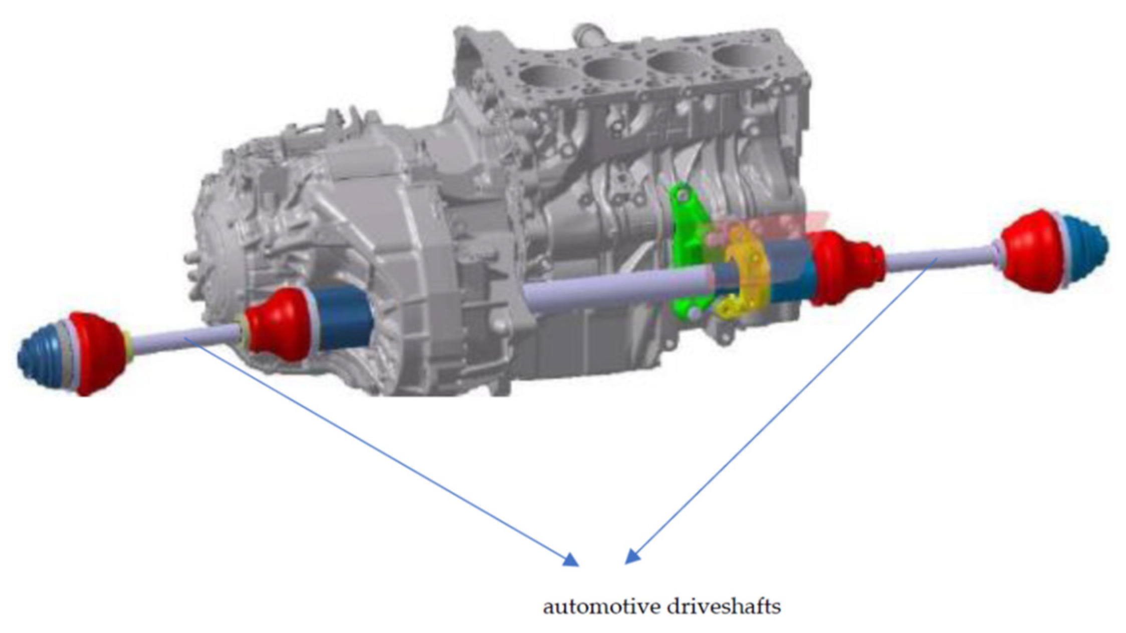
Figure 1. The automotive driveline.
Applsci 14 07681 g001
Figure 2. The details of the automotive driveshaft.
Applsci 14 07681 g002
Figure 3. The details of the joints.
Applsci 14 07681 g003
Figure 4. Schematical representation of movements for an AD.
Applsci 14 07681 g004
Figure 5. The geometry of the CVJ automotive driveshaft.
Applsci 14 07681 g005
Figure 6. Elements of DMADFTV.
Applsci 14 07681 g006
Figure 7. Natural frequency in torsion of (a) global tulip, (b) global bowl.
Applsci 14 07681 g007
Figure 8. Stationary DIBF for the global tulip β 1 = 15 o . (a) μ 1 > 0 (b) μ 1 < 0 .
Applsci 14 07681 g008
Figure 9. Stationary DIBF for the global bowl β 2 = 47 o . (a) μ 3 > 0 (b) μ 3 < 0 .
Applsci 14 07681 g009
Figure 10. SA of NFTV for GT, β 1 = 15 o . (a) ξ = 1.6 × 10 3 . (b) ξ = 4.3 × 10 3 .
Applsci 14 07681 g010
Figure 11. SVA of NFTV for GT, β 1 = 15 o . (a) ξ = 1.6 × 10 3 . (b) ξ = 4.3 × 10 3 .
Applsci 14 07681 g011
Figure 12. Phase portrait SA–SVA of NFTV for GT, β 1 = 15 o . (a) ξ = 1.6 × 10 3 . (b) ξ = 4.3 × 10 3 .
Applsci 14 07681 g012
Figure 13. SA of NFTV for GB, β 2 = 47 o . (a) ξ = 1.6 × 10 3 . (b) ξ = 6 × 10 3 .
Applsci 14 07681 g013
Figure 14. SVA of NFTV for global bowl, β 2 = 47 o . (a) ξ = 1.6 × 10 3 . (b) ξ = 6 × 10 3 .
Applsci 14 07681 g014
Figure 15. Phase portrait SA–SVA of NFTV for global bowl, β 2 = 47 o . (a) ξ = 1.6 × 10 3 . (b) ξ = 6 × 10 3 .
Applsci 14 07681 g015
Disclaimer/Publisher’s Note: The statements, opinions and data contained in all publications are solely those of the individual author(s) and contributor(s) and not of MDPI and/or the editor(s). MDPI and/or the editor(s) disclaim responsibility for any injury to people or property resulting from any ideas, methods, instructions or products referred to in the content.