Article

Study on the Effect of Operating Conditions on the Friction Pair Gap in a Wet Multi-Disc Clutch in a Helicopter Transmission System

1
School of Mechanical and Electrical Engineering, Central South University, Changsha 410083, China
2
State Key Laboratory of Precision Manufacturing for Extreme Service Performance, Central South University, Changsha 410083, China
3
AECC Hunan Aviation Powerplant Research Institute, Zhuzhou 412002, China
*
Author to whom correspondence should be addressed.
Appl. Sci. 2024, 14(17), 7751; https://doi.org/10.3390/app14177751
Submission received: 24 July 2024 / Revised: 28 August 2024 / Accepted: 30 August 2024 / Published: 2 September 2024

Abstract

:
The friction pair gap affects not only the temperature increase of the multi-disc wet clutch, but also the efficiency of the helicopter transmission system. Consequently, a rotational–axial engagement and disengagement-coupled kinetic model of a wet multi-disc clutch considering asperity contact, hydrodynamic lubrication, spline resistance, and a separating spring model are developed in this paper. The effects of operating conditions on the dynamic characteristics of the wet clutch are investigated. Further, the gap deviation coefficient is proposed to characterize the dynamic behavior of the friction pair gap. As the control oil pressure increases from 1.3 MPa to 1.7 MPa, the gap deviation coefficient increases by 8.6%. Moreover, as the rotation speed increases from 888 rpm to 2488 rpm and the lubricant oil temperature increases from 25 °C to 85 °C, the gap deviation coefficient decreases by 1.1% and 4.44%, respectively. Therefore, an appropriate increase in lubricant oil temperature and rotation speed can facilitate the friction pair gap to be more uniform. These results are useful for the development of optimal control strategies for aviation wet clutch systems.

1. Introduction

The wet multi-disc clutch is characterized by a more stable performance and lower torque impact, and is the key to realizing the variable speed output of helicopter rotor blades. Compared with automotive friction clutches, friction clutches for helicopters are characterized by severe running conditions, higher speeds, higher power, and power densities exceeding 4 kW/kg. The wet friction clutch for helicopters transmits torque exceeding 1 kN·m and power exceeding 1000 kW [1]. As demonstrated in Figure 1, the multi-disc wet clutch is usually composed of a piston, an input shaft, an output shaft, separating springs, several friction elements, and other components. Uninterrupted power shifting of helicopters is accomplished by controlling oil pressure to achieve the engagement and disengagement of the multi-disc wet clutch [2].
Recently, research on the dynamic behavior of the automobile clutch has mainly focused on the friction transmission mechanism of friction torque [3] and drag torque [4]. Wang et al. [5] studied the effect of friction pair gap distribution on low-speed viscous torque—the more uniform the gap distribution, the greater the viscous torque. Yu et al. [6,7,8] established a coupled numerical model of a wet friction clutch in the engagement process and analyzed the factors influencing friction torque. Zhang et al. [9] conducted a simulation study on the dynamic behavior of wet clutch engagement. Compared with the SAE#2 bench test, the research results showed that the engagement time error, maximum output torque error, and average output torque error were 4.86%, 3.87%, and 0.73%, respectively. The single friction pair of the wet friction clutch engagement process model was established in references [10,11,12,13,14], and the effects of material parameters, structure parameters, and operating conditions on the dynamic characteristics of the wet clutch in the engagement process were investigated, respectively. Bao et al. [15,16] analyzed the three groove shapes on the wear dynamics of the friction pair by studying the engagement dynamics of paper-based wet clutches.
Moreover, there are studies on the dynamic models of clutches considering the structure parameters. Wu et al. [17,18] analyzed the factors influencing the friction coefficient in the wet friction clutch running process and investigated the change mechanism of the friction coefficient. Wang et al. [19] developed a torque model for wet multi-disc clutches and investigated the effect of operating condition parameters on the tribological performance of the clutch during the running-in process. Chen et al. [20] established a wet friction clutch kinetic engagement model considering spline friction to study the effect of spline on the dynamic characteristics of the clutch engagement. Zheng et al. [21] established a wet multi-disc clutch separation dynamic model to study the dynamic characteristics of the wet clutch in the separation process. Niu et al. [22] used the segmented linear function method to establish a spline pair model. Meanwhile, the kinetic equations of the spline pair considering the double steel plate and the friction plate were established to investigate the vibration characteristics of the wet clutch and the dynamic load characteristics of the spline pair, respectively.
The wet multi-disc friction clutch is mostly used for high power and high torque transmission in high-speed helicopters. With the high rotation speed difference between the friction pair, centrifugal force causes oil film rupture and contraction, which causes many problems such as friction element displacement delay, sticking, and even failure to separate the friction pair. The long-term contact sliding between the friction plates and steel plates generates a large amount of frictional heat, ultimately resulting in thermal corrosion failure of the clutch [23,24,25]. Aiming to solve the problem of the friction components failing to separate, engineers designed waveform springs between steel plates, where the spring compression force is promoted in order to separate the clutch friction elements after the control oil pressure is released [26]. The load–deflection properties of waveform springs affect the response speed, smoothness of transmission torque, and service life of the wet clutch [27].
A review of the literature indicates that numerous researchers have carried out extensive studies on the engagement behaviors of wet friction clutches in automobiles. However, relatively little research has been conducted on the dynamic characteristics of aviation wet friction clutches with the high torque and power density necessary for helicopter transmission systems, especially regarding the distribution characteristics of the friction pair gap. Further, the friction pair gap not only the affects the temperature increase of the multi-disc wet clutch, but also the efficiency of the helicopter transmission system. Therefore, we aim to to further investigate the dynamic behaviors of the aviation wet friction clutch for helicopters in the power shifting process, and to explore the influence of operating conditions on the friction pair gap during clutch operation. In Section 2, a kinetic model of the wet multi-disc clutch in the whole operating process is established. In Section 3, the changing laws of the friction pair gap and drag torque are analyzed. In Section 4, the law of operation conditions influeincing the dynamic response of the friction element is investigated. The conclusions are summarized in Section 5.

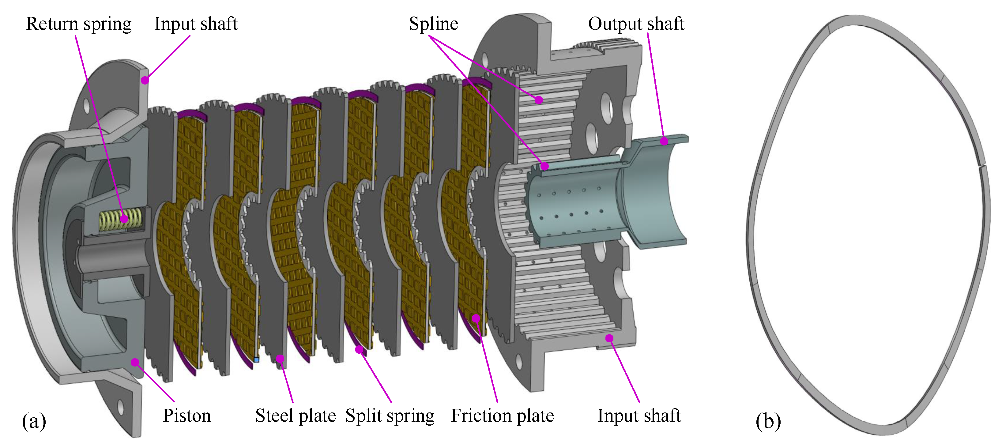
2. Mathematical Model of Multi-Disc Wet Clutch

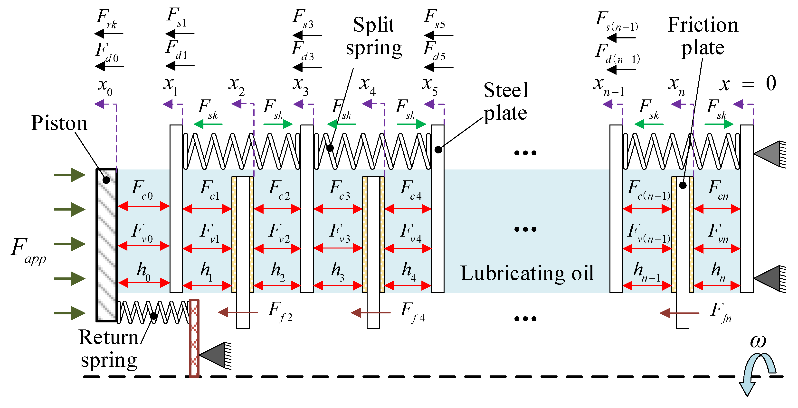
2.1. Piston and Friction Components Axial Kinetic Model

The piston and friction elements of the wet clutch are driven by the control oil pressure, which undergo an axial shift and circumferential rotation. The friction elements are successively numbered and the corresponding axial forces are analyzed in Figure 2.
The displacement of the i-th element can be obtained by
x i = ( n + 1 i ) h o + j = i n H d j k = i n h k , i = 0 , 1 n
where H d j is the steel plate or friction plate thickness, h o is the initial gap of friction pairs, h k is the friction pair gap, and n is the number of friction pairs.
The kinetic model of the friction elements and piston axial was established based on force balance conditions, as shown in Equation (2) [3].
F c 0 + F v 0 + F d 0 F a p p F c 1 + F v 1 + F s 1 + F d 1 F c 0 F v 0 F c 2 + F v 2 + F f 2 F c 1 F v 1 F c ( n 1 ) + F v ( n 1 ) + F s ( n 1 ) + F d ( n 1 ) F c ( n 2 ) F v ( n 2 ) F c n + F v n + F f n F c ( n 1 ) F v ( n 1 ) + k r 0 0 0 0 0 k s k s 0 0 0 0 0 0 0 0 k s k s k s k s 0 0 0 0 0 h o h 0 h o h 1 h o h 2 h o h n 1 h o h n = m p m s m f m s m f x 0 x 1 x 2 x n 1 x n
where m p is the piston mass, m s is the steel plate mass, m f is the friction plate mass, F c i is asperities bearing capacity in the friction pair, F v i is the oil film bearing capacity in the friction pair, F s i is the friction force between the steel plate and the spline, F f i is the friction force between the friction plate and the spline, F d i is the damping force of the steel plate, F a p p is the driven force of the hydraulic oil, and k r is the stiffness of the return spring. The wave spring stiffness k s is described as follows [27]:
k s = 16 k E b δ 3 N 4 π 3 D M 3
where D M is the center diameter of the wave spring, N is the wave number of the wave spring, b is the wave spring width, and δ is the wave spring thickness.
The damping force between the steel plate and spline is described as follows:
F d = c s x i
The torque is transmitted from the steel plate to the input shaft via the spline and the torque is transmitted from the friction plate to the output shaft via the spline. Therefore, there is friction resistance between the friction components and the spline during the friction element axial shift [20]. The spline resistance forces are deduced as follows:
F f i = sign ( x i ) μ s T f i R f cos ( α )
F s i = sign ( x i ) μ s T f i R s cos ( α )
where μ s is the spline friction coefficients; T f i is the torque transmitted by the friction pair; α is the pressure angle of the spline; and R s and R f are the spline pitch circle radius on the friction plate and steel plate, respectively.

2.2. Lubrication Model of Friction Pair

It is assumed that the steel plate and friction plate are always parallel and are not deformed during movement, the oil film pressure is distributed axisymmetrically, and the friction pair is full of lubrication oil. Based on the research results of Patir and Cheng [28], the average flow model, pressure flow factor, the shear flow factor were considered, and the modified Reynolds equation was deduced in Equation (7).
1 r d d r r ϕ r ( h 3 + 12 ψ d m ) d p d r = 12 η d h ¯ t d t h ¯ t = h 2 1 + erf ( h 2 σ ) + σ 2 π e ( h 2 2 σ 2 ) d h t ¯ d t = d h t ¯ d h d h d t = 1 2 1 + erf h 2 σ d h d t
where the radial pressure flow factor is ϕ r = 1 0.9 e 0.56 h / σ ; h is the oil film thickness; ψ and d m represent the permeability and thickness of the friction material, respectively; and η is the lubricant oil viscosity.
According to the structural characteristics of the wet clutch, there is only the radial pressure of the lubricant oil at the inner and outer diameters of the friction pair; the boundary conditions of Equation (7) are determined as p v ( r = R i ) = p v ( r = R o ) = 0 . The oil film average pressure between the friction pairs is described as follows [17]:
p v ( r ) = 3 η 2 ϕ r ( h 3 + 12 ψ d ) r 2 R o 2 + ( ln r ln R ) R o 2 R i 2 ln R i ln R o 1 + erf ( h 2 σ ) d h d t
where R i and R o represent the inner radius and outer radius of the friction pair, respectively.
By integrating the average pressure of the oil film in the lubricated area A n , the oil film bearing capacity F v between the friction pairs is obtained as follows:
F v = ( 1 A r e d C ) 0 2 π d θ R i R o p v r d r

2.3. Friction Pair Asperity Contact Model

In practice, it is assumed that the surface roughness of the friction plate and the steel plate obey a Gaussian density distribution with zero means [7]. Further, the asperity contact between the friction pairs is mainly elastic–plastic deformation [29]. Based on the elastic–plastic contact theory, the rough contact area A c between the friction pair can be derived as [7]:
A c = γ π 2 A n ( π λ R σ ) 2 H ( x H ) 2 1 2 π exp ( x 2 2 ) d x
where λ and R denote the density and radius of the asperity, respectively; σ is the RMS roughness of the friction pairs, σ = σ f 2 + σ s 2 ; σ f is the roughness of the friction plate; σ s is the roughness of the steel plate; γ is the deformation coefficient; A c is the asperity contact area; A n is the nominal contact area; and H = h / σ is the film thickness ratio.
Patir and Cheng [28] used numerical integration and curve fitting to obtain the relationship between the asperity contact pressure p c and the film thickness ratio H on rough surfaces; the asperity contact pressure is calculated as follows:
p c ( H ) = K E × 4.4086 × 10 5 × ( 4 H ) 6.804 H < 4.0 p c ( H ) = 0 H 4.0
where K is the contact coefficient of the friction interface and E denotes the equivalent Young’s modulus.
K = 8 2 15 π λ R σ 2 σ R 1 E = 1 2 ( 1 υ 1 2 E 1 + 1 υ 2 2 E 2 )
where E 1 and E 2 are Young’s modulus of the steel plate and the friction plate, respectively, and υ 1 and υ 2 are Poisson’s ratio of the steel plate and the friction plate, respectively.
The nominal contact area of the friction pair consists of the rough contact area and the fluid lubrication area, and the ratio of the rough contact area to the nominal contact area is defined as the contact ratio C, which is used to assess the different contact states between the friction pair. The contact ratio C is presented as follows:
C = A c A n = γ π 2 λ R σ 2 2 1 + H 2 1 erf H 2 2 π H exp H 2 2
The asperities bearing capacity F c is calculated using Equation (14).
F c = A r e d C 0 2 π d θ R i R o p c r d r

2.4. Torque Balance Model

In wet friction clutch engagement, the mechanism for transmitting the torque gradually transforms from the viscous torque T c generated by the shearing oil film to the friction torque T v generated by the asperities contact as the control oil pressure increases, whereas in the disengagement process, the opposite is true. The friction torque T c and the viscous torque T v are denoted as follows:
T v = ( 1 A r e d C ) 0 2 π d θ R i R o η ( φ f s + φ f ) r 3 ω r e l h d r T c = A r e d C f c 0 2 π d θ R i R o r 2 p c d r
where φ f and φ f s denote the pressure flow factor and the shear flow factor, respectively, and f c represents the friction coefficient of the asperities contact, which can be obtained through pin-on-disc experiments [30].
f c = 0.035 + 23 e 2.67 ( ln T 3.2 ) ( 28.3 p e ) 0.4 0.87 5.16 + 0.08 e 0.005 T 1 e 0.2 v 1 + 0.01 ln ( 4 v + 1 ) e 0.005 T 0.005 ln ( 28.3 p e )
where T is the lubricant oil temperature, v is the velocity difference, and p e represents the effective pressure of the friction pair.
The wet clutch transmission torque consists of friction torque and viscous torque. Therefore, the torque balance equation of the wet multi-disc clutch is given as follows:
I f d ω 2 d t = i = 1 n T c i + i = 1 n T v i T r
where I f and T r represent the inertia and resistant torque of the output shaft, respectively.

3. Numerical Simulation

3.1. Simulation Parameters and Solution

An axial-rotational-coupled kinetic mathematical simulation model is established in MATLAB/Simulink. In the coupled-model solution procedure, firstly, the initial state or the calculation result of the previous time step is used to calculate the force on the friction element. Secondly, the acceleration, velocity, and displacement of the friction elements are obtained by solving the axial force and torque balance equations. Then, the displacement and velocity of the friction element are used to calculate the friction pair gap and the variance rate of the friction pair gap. Finally, the simulation calculation is repeated until the simulation termination time.
The maximum simulation time step is 10 μs. The initial values of the oil film thickness for the 0-th friction pairs and the 1-th friction pairs are 0.4 mm and 0.45 mm, respectively. The remaining simulation parameters of the rotational-axial-coupled kinetic model are listed in Table 1.
The control oil pressure curve is illustrated in Figure 3a. Firstly, the control oil pressure linearly increases from zero to a maximum pressure of 1.6 MPa in 0.2–0.35 s. Secondly, the control oil pressure is maintained at 1.6 MPa to 2 s. Thirdly, the control oil pressure linearly decreases from 1.6 MPa to zero in 2–2.3 s. Finally, the control oil pressure is always maintained at zero after 2.3 s.

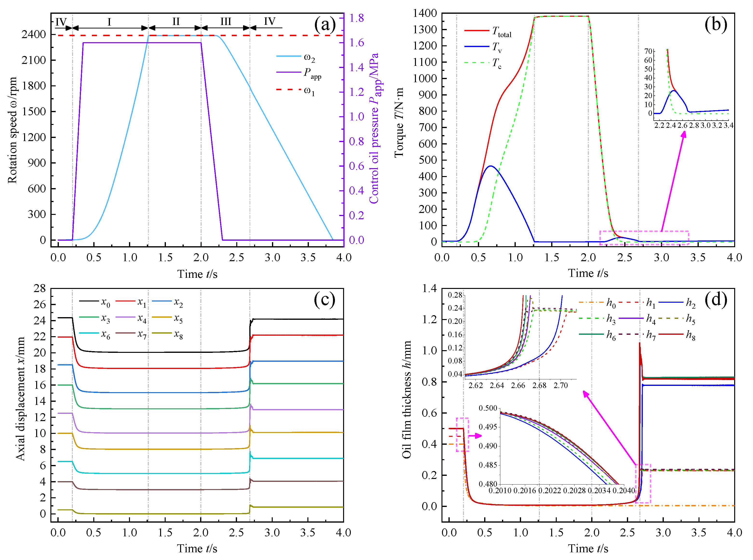
3.2. Dynamic Response of Wet Friction Clutch

Figure 3a,b demonstrate the wet clutch rotation speed and drag torque dynamic response curves, respectively. As the control oil pressure increases, the wet friction clutch successively goes through the engagement process (I), the engagement state (II), and the disengagement process (III), and finally returns to the disengagement state (IV). When the wet friction clutch is in the engagement process, as the control oil pressure increases, the oil film thickness decreases, and the viscous torque first increases and then decays to zero, while the friction torque increases, the output shaft speed increases to 2388 rpm, and then remains constant. However, when the clutch is in the disengagement process, as the control oil pressure decreases, the frictional torque gradually decreases to zero, the oil film thickness increases, the viscous torque increases and then decays, and the output shaft speed decreases to zero.
Figure 3c illustrates the friction element axial displacement curves, where the axial displacement of the friction components decrease to a stabilized value and then increase to a stabilized value with the control oil pressure. The oil film thickness can be obtained from Equation (1) and the corresponding result is shown in Figure 3d. In the friction clutch engagement process, the friction elements respond sequentially from left to right, while in the disengagement process, the friction elements respond sequentially from right to left, the first steel plate follows the piston movement, resulting in a gap of almost zero throughout the clutch disengagement process.

4. Results and Analysis
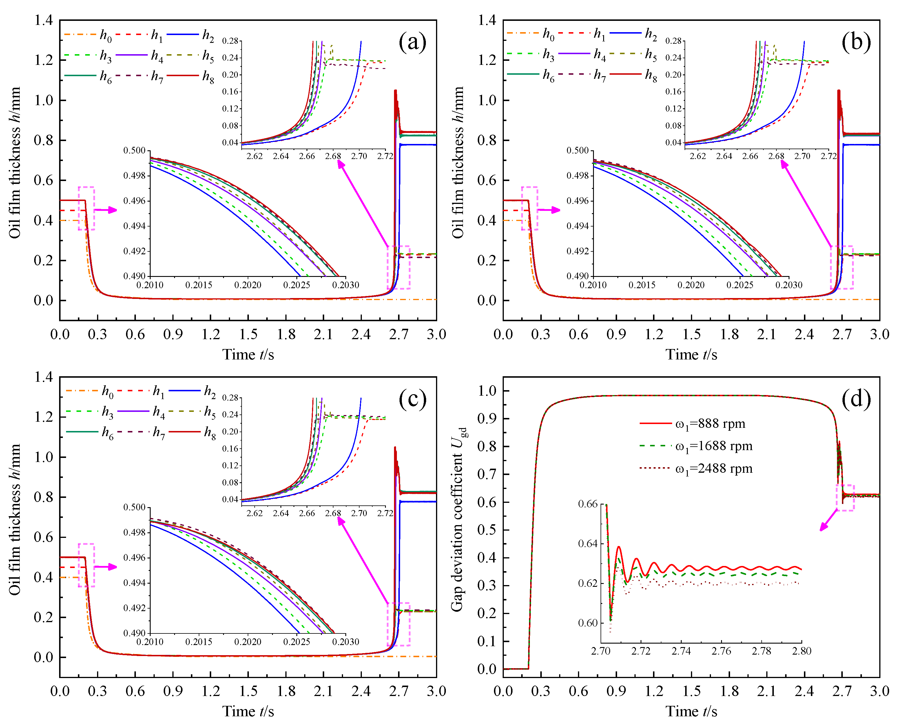
The distribution of the friction elements cannot be accurately assessed using only the oil film thickness during clutch operation, as shown in Figure 3d.Therefore, the gap deviation coefficient is proposed as an evaluation index in this paper, which is defined as Equation (18). The gap deviation coefficient ranges from 0 to 1. The smaller the gap deviation coefficient, the more uniformly the friction element is distributed.
U g d = 1 n i = 0 n h i h o h o

4.1. Rotation Speed

Under the conditions of control oil pressure of 1.6 MPa, and the rotation speeds are set to 888 rpm, 1688 rpm, and 2488 rpm. The corresponding oil film thickness response curves are illustrated in Figure 4a–c, respectively. The gap deviation coefficient can be calculated by Equation (18), and the corresponding result is illustrated in Figure 4d. With the variable of the control oil pressure, the gap deviation coefficient successively undergoes a process of increasing, stabilizing, and then decreasing to a constant value. The results of the engagement time, disengagement time, and gap deviation coefficient after the friction element separation for different rotation speeds are presented in Table 2.
As the rotation speed increases, the engagement time increases from 0.8789 s to 1.3126 s, an increase of 0.4337 s (49.3%); the disengagement time increases from 2.7044 s to 2.7065 s, an increase of 0.0021 s (0.08%); and the gap deviation coefficient after the friction element separation reduces from 0.6267 to 0.6198, a reduction of 0.0069 (1.1%). Thus, the rotation speed has a negligible effect on the disengagement time. The higher the rotation speed, the higher the relative shear speed of the oil film, and the higher the hydrodynamic pressure, which helps the friction elements separate.

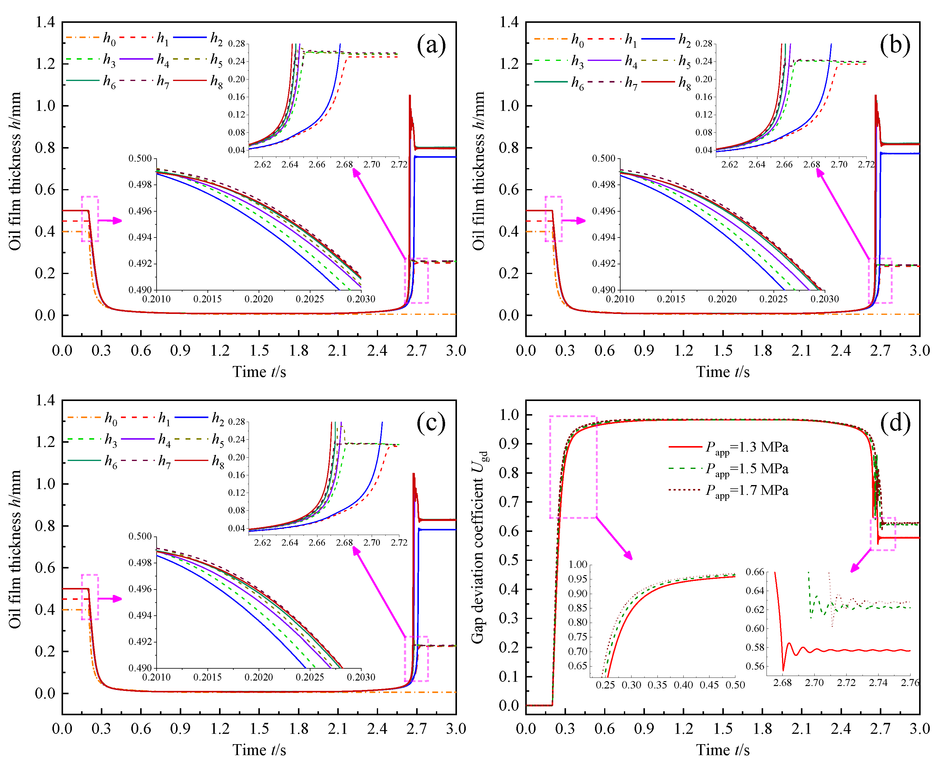
4.2. Control Oil Pressure

Under the conditions of a rotation speed of 2488 rpm, the maximum control oil pressure is set to 1.3 MPa, 1.5 MPa, and 1.7 MPa, and the corresponding oil film thickness response curves are illustrated in Figure 5a–c, respectively. The gap deviation coefficient can be calculated by Equation (18), and the corresponding result is illustrated in Figure 5d. The results of the engagement time, disengagement time, and gap deviation coefficient after the friction element separation for different oil pressures are demonstrated in Table 3.
As the control oil pressure increases, the engagement time decreases from 1.459 s to 1.2389 s, a decrease of 0.2201 (15.1%); the disengagement time increases from 2.6864 s to 2.7109 s, an increase of 0.0245 (0.91%); and the gap deviation coefficient after the friction element separation increases from 0.5774 to 0.627, an increase of 0.0496 (8.6%). Consequently, the control oil pressure has a negligible effect on the disengagement time. As the control oil pressure increases, the contact pressure of the friction pair increases, the asperities contact plastic deformation is more serious, and the disengagement force decreases, which results in deteriorating friction elements separation uniformity.

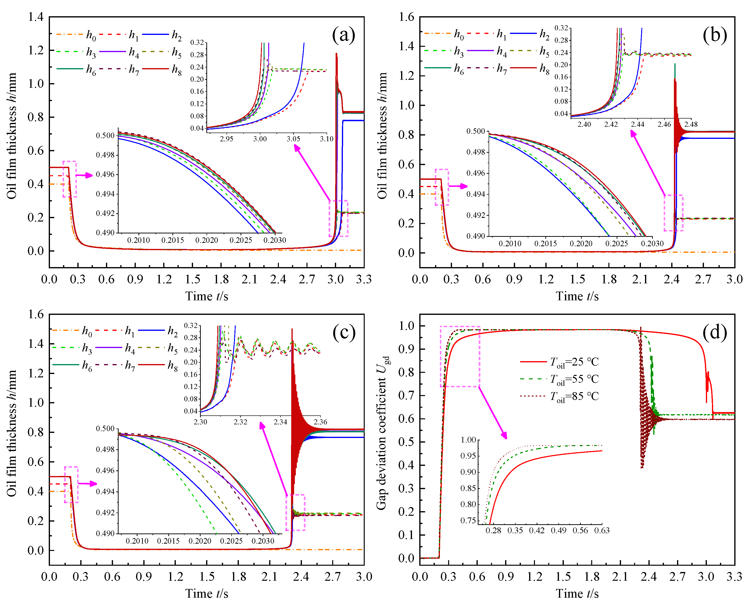
4.3. Lubricant Oil Temperature

The lubricant oil viscosity is affected by temperature, and the lubricant oil viscosity-temperature relationship is expressed in Equation (19) according to Roelands viscosity equation [31]:
η = η 0 exp ( ( ln η 0 + 9.67 ) ( ( 1 + 5.1 × 10 9 P ) 0.68 × ( T o i l 138 T o i l 0 138 ) 1.1 1 ) )
Under the conditions of a rotation speed of 2488 rpm and control oil pressure of 1.6 MPa, the lubricating oil temperature is set to 25 °C, 55 °C, and 85 °C. The corresponding oil film thickness response curves are illustrated in Figure 6a–c, respectively. The gap deviation coefficient can be calculated by Equation (18), and the corresponding result is illustrated in Figure 6d and Table 4.
As the lubricant oil temperature increases, the engagement time increases from 1.3536 s to 1.4617 s, an increase of 0.1081 s (8%); the disengagement time reduces from 3.0698 s to 2.3196 s, a reduction of 0.7502 s (24.4%); and the gap deviation coefficient after the friction element separation decreases from 0.6255 to 0.5977, a reduction of 0.0278 (4.44%). Further, the higher the lubrication oil temperature, the more significant the vibration that occurs during the clutch disengagement process. The main reason is that as the lubricant oil temperature increases, the lubricant oil viscosity decreases exponentially, and the oil film shear force and oil film bearing capacity reduce, which results in a faster disengagement response. Hence, as the lubricant oil temperature increases, the friction elements are more uniformly disengaged.

5. Conclusions

A dynamic model of a wet clutch with eight friction pairs considering the spline friction and separating spring was established in this paper to investigate the effects of rotational speed, control oil pressure, and lubricant oil temperature on the dynamic behaviors of friction elements. The corresponding research results are briefly summarized as follows:
(1) As shown in Figure 7, as the rotation speed (from 888 rpm to 2488 rpm) and lubricant oil temperature increase (from 25 °C to 85 °C), the clutch engagement times increase by 49.3% (from 0.8789 s to 1.3126 s) and 8% (from 1.3536 s to 1.4617 s). The increase in control oil pressure (from 1.3 MPa to 1.7 MPa) shortened the clutch engagement time (by 15.1% from 1.459 s to 1.2389 s), whereas the clutch disengagement time increased by 0.08% and 0.91% with rotation speed and control oil pressure, respectively, and decreased by 24.4% with lubricant oil temperature. Moreover, as the rotation speed and lubricant oil temperature increased, the the gap deviation coefficient after the friction element separation decreased (by 1.1% and 4.44% respectively), and the friction elements separation became more uniform.
(2) The higher the control oil pressure, the more asperities undergo plastic deformation, and the smaller elastic deformation force of the asperities on the friction pairs, which results in an increase in the gap deviation coefficient after friction element separation and a deterioration in the uniformity of the friction element separation.
(3) Increasing the lubricant oil temperature can rapidly decrease the lubricant oil viscosity and oil film thickness, and vibration of the friction elements occurs significantly during the clutch disengagement process. This results in a decrease in the shear force and bearing capacity of the lubrication oil film, which helps the friction element to separate uniformly.
(4) In order to uniformly separate the friction elements in the aviation wet friction clutch for the helicopter transmission system, the lubricant oil temperature should be appropriately increased, the control oil pressure should be appropriately reduced, and the rotational speed should be appropriately increased under the condition of ensuring that the clutch can achieve the torque transmission requirements.

Author Contributions

Conceptualization, X.L. and H.Y.; methodology, X.L.; software, X.L.; validation, X.L., D.W. and J.W.; formal analysis, M.Y.; investigation, Y.X.; resources, K.L.; data curation, X.L.; writing—original draft preparation, X.L.; writing—review and editing, D.W.; visualization, M.Y.; supervision, H.Y.; project administration, H.Y.; funding acquisition, H.Y. All authors have read and agreed to the published version of the manuscript.

Funding

This research was funded by the National Natural Science Foundation of China (grant number 52075552).

Institutional Review Board Statement

Not applicable.

Informed Consent Statement

Not applicable.

Data Availability Statement

The raw data supporting the conclusions of this article will be made available by the authors on request.

Conflicts of Interest

The authors declare no conflicts of interest.

References

  1. Bao, H.; Kong, W.D.; Hou, X.N.; Zhu, R.P. Analysis on temperature field of friction pair of aviation friction clutch based on different groove shapes of friction disk. J. Mech. Sci. Technol. 2021, 35, 3735–3742. [Google Scholar] [CrossRef]
  2. Li, M.; Khonsari, M.M.; McCarthy, D.M.C.; Lundin, J. Parametric analysis for a paper-based wet clutch with groove consideration. Tribol. Int. 2014, 80, 222–233. [Google Scholar] [CrossRef]
  3. Bao, H.Y.; Huang, W.; Lu, F.X. Investigation of engagement characteristics of a multi-disc wet friction clutch. Tribol. Int. 2021, 159, 106940. [Google Scholar]
  4. Leister, R.; Najafi, A.F.; Gatti, D.; Kriegseis, J.; Frohnapfel, B. Non-dimensional characteristics of open wet clutches for advanced drag torque and aeration predictions. Tribol. Int. 2020, 152, 106442. [Google Scholar] [CrossRef]
  5. Wang, P.C.; Katopodes, N.; Fujii, Y. Statistical modeling of plate clearance distribution for wet clutch drag analysis. SAE. Int. J. Passen. Car. 2018, 11, 76–88. [Google Scholar] [CrossRef]
  6. Yu, L.; Ma, B.; Chen, M.; Li, H.Y.; Liu, J.K.; Zheng, L.J. Numerical and experimental studies on the characteristics of friction torque based on wet paper-based clutches. Tribol. Int. 2019, 131, 541–553. [Google Scholar] [CrossRef]
  7. Yu, L.; Ma, B.; Chen, M.; Xue, J.; Zhao, P. Variation mechanism of the friction torque in a Cu-based wet clutch affected by operating parameters. Tribo. Int. 2020, 147, 106169. [Google Scholar] [CrossRef]
  8. Yu, L.; Ma, B.; Chen, M.; Li, H.Y.; Liu, J.K. Experimental study on the friction stability of paper-based clutches concerning groove patterns. Ind. Lubr. Tribol. 2020, 72, 541–548. [Google Scholar] [CrossRef]
  9. Zhang, Z.; Zhu, L.C.; Zheng, X.D. Simulations versus tests for dynamic engagement characteristics of wet clutch. Cogn. Robot. 2021, 1, 125–133. [Google Scholar] [CrossRef]
  10. Wu, P.H.; Xu, J.; Zhou, X.J. Numerical and experimental research on engagement process of wet multi-plate friction clutches with groove consideration. Proc. Inst. Mech. Eng. Part J. Eng. Tribol. 2019, 233, 1464–1482. [Google Scholar] [CrossRef]
  11. Zhang, Z.G.; Zou, L.; Liu, H.; Feng, J.; Chen, Z.G. Response Characteristics of Dynamic Torque for Wet Clutch Engagement: A Numerical and Experimental Study. Shock. Vib. 2021, 23021, 5522998. [Google Scholar] [CrossRef]
  12. Zhang, Z.G.; Zou, L.; Qing, H. Analysis of Factors Affecting Vibration During Wet Clutch Engagement. IEEE Access 2021, 9, 34298–34306. [Google Scholar] [CrossRef]
  13. Wang, Y.Z.; Li, Y.; Liu, Y.; Zhang, W. Modeling and experimental research on engaging characteristics of wet clutch. Ind. Lubr. Tribol. 2019, 71, 94–101. [Google Scholar] [CrossRef]
  14. Wang, Y.; Yang, K.; Wu, X.Y. Structural design and friction performance test of a new conical groove friction disks in wet clutch. Appl. Sci. 2021, 11, 7231. [Google Scholar] [CrossRef]
  15. Bao, H.Y.; Zhang, C.; Hou, X.N.; Lu, F.X. Wear characteristics of different groove-shaped friction pairs of a friction clutch. Appl. Sci. 2021, 11, 284. [Google Scholar] [CrossRef]
  16. Yang, X.G.; Bao, H.Y.; Zhang, C.; Tan, W.Z.; Zhu, R.P. Influence of Groove Type on Friction Coefficient of Wet Friction Clutch Pair. Int. J. Automot. Technol. 2024, 25, 13–21. [Google Scholar] [CrossRef]
  17. Wu, B.Z.; Qin, D.T.; Hu, J.J.; Wang, X.; Wang, Y.; Lv, H. Analysis of influencing factors and changing laws on friction behavior of wet clutch. Tribol. Int. 2021, 162, 107125. [Google Scholar] [CrossRef]
  18. Wu, B.Z.; Qin, D.T.; Hu, J.J.; Liu, Y.G. Experimental data mining research on factors influencing friction coefficient of wet clutch. J. Tribol. 2021, 143, 121802. [Google Scholar] [CrossRef]
  19. Wang, Q.; Ma, B.; Yu, L.; Xiong, C.B.; Zheng, L.J. Effects of operating conditions on the tribological behavior of a wet multi-disc clutch during the running-in process. Tribol. Int. 2023, 179, 108096. [Google Scholar] [CrossRef]
  20. Chen, M.; Zhang, B.; Feng, Y.Q.; Wang, L.; Wang, H. Numerical and Experimental Studies of the Attenuation Characteristics of Friction Torque in a Wet Multidisc Clutch. Appl. Sci. 2021, 11, 814. [Google Scholar] [CrossRef]
  21. Zheng, L.J.; Ma, B.; Chen, M.; Yu, L.; Xue, J.Q. Numerical studies on the dynamic characteristics of a wet multi-disc clutch during the disengaging process. J. Mech. Sci. Technol. 2022, 36, 3277–3289. [Google Scholar] [CrossRef]
  22. Niu, Y.K.; Bao, H.Y.; Huang, W.; Tan, W.Z.; Peng, Z. Dynamics modeling and simulation analysis of wet clutch considering spline pair. Ind. Lubr. Tribol. 2023, 75, 866–874. [Google Scholar] [CrossRef]
  23. Pointner-Gabriel, L.; Schermer, E.; Schneider, T.; Stahl, K. Experimental analysis of oil flow and drag torque generation in disengaged wet clutches. Sci. Rep. 2023, 13, 17193. [Google Scholar] [CrossRef] [PubMed]
  24. Mahmud, S.F.; Pahlovy, S.; Kubota, M.; Ogawa, M.; Tajajura, N. A Simulation Model for Predicting High Speed Torque Jump Up Phenomena of Disengaged Transmission Wet Clutch; SAE Technical Paper; SAE International: Warrendale, PA, USA, 2017. [Google Scholar]
  25. Goszczak, J.; Leyko, J.; Mitukiewicz, G.; Batory, D. Experimental Study of Drag Torque between Wet Clutch Discs. Appl. Sci. 2022, 12, 3900. [Google Scholar] [CrossRef]
  26. Gürbüz, H.; Schulz, J.; Kücükay, F.; Elard, F.S.; Ott, S. Significant Drag Torque Reduction and Improved Clutch Dynamics by Innovative, Very Compact Separating Springs for Wet Clutches; Springer: Berlin/Heidelberg, Germany, 2021; pp. 177–190. [Google Scholar]
  27. Wang, H.P.; Zhu, C.; Yang, X.G.; Niu, Y.K.; Bao, H.Y.; Zhu, R.P. Study on the engagement characteristics of wet multi-plate friction clutch based on separating spring. Forsch. Ingenieurwes. 2024, 88, 3. [Google Scholar] [CrossRef]
  28. Patir, N.; Cheng, H.S. An Average Flow Model for Determining Effects of Three-dimensional Toughness on Partial Hydrodynamic Lubrication. J. Lubr. Technol. 1979, 100, 12–17. [Google Scholar] [CrossRef]
  29. Kogut, L.; Etsion, I. A finite element based elastic-plastic model for the contact of rough surfaces. Tribol. Trans. 2003, 46, 383–390. [Google Scholar] [CrossRef]
  30. Zhao, E.H.; Ma, B.; Li, H.Y. Numerical and experimental studies on tribological behaviors of Cu-based friction pairs from hydrodynamic to boundary lubrication. Tribol. Trans. 2018, 61, 347–356. [Google Scholar] [CrossRef]
  31. Houpert, L. New results of traction force calculations in elastohydrodynamic contacts. J. Tribol. 1985, 107, 241–245. [Google Scholar] [CrossRef]
Figure 1. (a) Three-dimensional structure of the wet friction clutch. (b) The separating spring.
Applsci 14 07751 g001
Figure 2. Axial force model of the multi-disc wet clutch.
Applsci 14 07751 g002
Figure 3. The response curve of: (a) rotation speed, (b) drag torque, (c) axial displacement, and (d) oil film thickness in clutch operation.
Applsci 14 07751 g003
Figure 4. The response curves of oil film thickness for (a) 888 rpm, (b) 1688 rpm, and (c) 2488 rpm. (d) The gap deviation coefficient.
Applsci 14 07751 g004
Figure 5. The response curves of the oil film thickness for (a) 1.3 MPa, (b) 1.5 MPa, (c) 1.7 MPa, and (d) the gap deviation coefficient.
Applsci 14 07751 g005
Figure 6. The response curves of the oil film thickness for (a) 25 °C, (b) 55 °C, and (c) 85 °C. (d) The gap deviation coefficient.
Applsci 14 07751 g006
Figure 7. The results of the engagement time, disengagement time, and gap deviation coefficient after friction element separation for different operating conditions.
Applsci 14 07751 g007
Table 1. Simulation input parameters.
ParameterValueParameterValue
Outer radius of friction pairs R o 0.094 mInertia of output shaft I f 0.3 kg·m2
Outer radius of friction pairs R i 0.06 mThickness of friction plate H f d 0.003 m
Number of friction pairs n8Thickness of steel plate H s d 0.002 m
Return spring stiffness k r 1.52 × 10⁶ N·m−1Asperities density λ 7 × 10⁷ m−2
Input rotation speed ω 1 2388 rpmAsperities radius R8 × 10−4 m
Control oil pressure P a p p 1.6 MPaRMS roughness σ 8.41 × 10⁻⁶ m
Initial gap of friction pairs h o 5 × 10⁻⁴ mEquivalent Young’ modulus E 4.7 × 10⁹ Pa
Resistance torque T r 460 N·mNon-groove area coefficient A r e d 0.78
Permeability ψ 4 × 10⁻¹³ m2Friction material thickness d m 0.001 m
Mass of friction plate m f 0.6 kgMass of piston m p 3 kg
Mass of steel plate m s 0.45 kgLubricant oil density ρ 875 kg·m−3
Spline friction coefficient μ s 0.1Damping coefficient c s 0.08 N·s·m−1
Table 2. The results of the engagement time, disengagement time, and gap deviation coefficient after the friction element separation for different rotation speeds.
Rotation Speed/rpmEngagement Time/sDisengagement Time/sGap Deviation Coefficient
8880.87892.70440.6267
16881.08822.70530.6238
24881.31262.70650.6198
Table 3. The results of the engagement time, the disengagement time, and the gap deviation coefficient after the friction element separation for different oil pressure.
Oil Pressure/MPaEngagement Time/sDisengagement Time/sGap Deviation Coefficient
1.31.45902.68640.5774
1.51.38782.69810.6228
1.71.23892.71090.6270
Table 4. The results of the engagement time, disengagement time, and gap deviation coefficient after the friction element separation for different oil temperatures.
Oil Temperature/°CEngagement Time/sDisengagement Time/sGap Deviation Coefficient
251.35363.06980.6255
551.36872.43700.6179
851.46172.31960.5977
Disclaimer/Publisher’s Note: The statements, opinions and data contained in all publications are solely those of the individual author(s) and contributor(s) and not of MDPI and/or the editor(s). MDPI and/or the editor(s) disclaim responsibility for any injury to people or property resulting from any ideas, methods, instructions or products referred to in the content.

