Abstract
This study investigates bidirectionally sinusoidal corrugated steel shells using finite element analysis (FEA) software, primarily ABAQUS 2017, supplemented by RFEM 6.05 for an initial result comparison. The research aims to establish a robust numerical solution to understand the structural behaviour of these shells under static and dynamic loading. Starting with meticulous calculations for a selected structural element, the paper emphasises a comparative analysis between ABAQUS and RFEM, offering valuable insights into simulating the responses of corrugated steel shells. A distinctive contribution of this research lies in its novel and comprehensive parametric analysis of these shells under static and dynamic loading, an area that has not been explored in previous studies. The study systematically explores various model parameters, including geometrical and mechanical properties, with detailed analyses revealing their influences on deformation, stress distribution, dynamic properties, and behaviour. Another key feature is the development of a coded script that systematically generates diverse numerical models, allowing for a thorough exploration of the structural system’s response. This study advances our understanding of the structural behaviour of bidirectionally sinusoidal corrugated steel shells. These findings are set to enhance structural analysis and design practices by optimising parameters for improved performances in various engineering applications.
1. Introduction
1.1. Motivation and Literature Overview
Steel structures have become integral in the construction industry, celebrated for their versatility, strength, and efficiency. Unlike concrete, steel allows for the design and implementation of complex geometries that can substantially reduce material consumption and, in turn, lower the overall cost of construction projects. This advantage is particularly important in an era where sustainable practices and cost-effective solutions are tremendously sought after. The push for sustainability has made resource efficiency a critical factor in civil engineering, and steel’s ability to minimise material utilisation plays a crucial role in meeting these demands.
The ability to create sophisticated shapes with steel offers not only economic benefits, but also opens up new possibilities in civil engineering from structural and architectural points of view. Oval et al. described in [1] selected methods for finding patterns for shell structures, highlighting their potential to enhance both the aesthetic appeal and structural efficiency of engineered systems. Their research emphasises how innovative geometric configurations can lead to a more effective load distribution and improved performance in complex structural designs. Complex steel structures can be prefabricated with immense precision, reducing waste and enhancing construction speed and safety. Prefabrication also ensures better quality control, as components are manufactured in a controlled environment and then assembled on-site, leading to fewer defects and a more streamlined construction process. Moreover, steel’s inherent properties, such as a high tensile strength and ductility, make it an ideal material for constructing buildings that need to withstand dynamic loads, such as those from wind or seismic activity.
Although the understanding of steel structures has greatly evolved in recent years, there are still some particular areas that have significant development potential. Among them are bidirectionally sinusoidal corrugated steel shells, which find practical applications in several areas within the construction industry.
In structural engineering, various types of steel webs are utilised in welded plate girders to enhance their performance and efficiency. Traditional flat webs provide straightforward load transfer, but can be prone to a local loss of stability under high loads. To address this issue, corrugated webs have been introduced, offering an increased stability and resistance to buckling without significantly increasing material consumption. Trapezoidal and sinusoidal corrugations are common examples. Sokołowski and Kamiński (2015) explored the reliability issues associated with corrugated I-beams, emphasising their improved stability compared to flat webs [2]. Sokołowski and Kamiński (2016) applied the stochastic finite element method to further analyse the performance of these corrugated web steel plate girders, demonstrating enhanced resistance under various conditions [3]. Sokołowski and Kamiński (2017) extended this work to investigate the impact of corrosion and fire on the reliability of corrugated web girders, revealing additional benefits of corrugated designs in maintaining structural integrity under adverse conditions [4].
Research by Kiymaz et al. (2010) focused on the transverse load-carrying capacity of sinusoidally corrugated steel web beams with web openings, showcasing the advantages of sinusoidal corrugations in load distribution [5]. Feng et al. (2021) examined methods for determining the minimum number of stiffeners required for stiffened corrugated steel walls, further highlighting the structural benefits of corrugation patterns [6]. Eldib (2009) provided insights into the shear buckling strength of curved corrugated steel webs for bridges, demonstrating the improved performance of these advanced geometries in practical applications [7]. Perliński (2017) analysed the stability of one- and two-way sinusoidally corrugated steel sections, illustrating their superior structural performance compared to conventional designs [8].
In addition to their use in welded plate girders, bidirectionally sinusoidal corrugated steel plates are employed in steel sandwich panels. These panels consist of two thin steel face sheets bonded to a lightweight core. This core, often made from corrugated steel, enhances the panel’s load-bearing capacity and overall stiffness while maintaining a low weight. Gajdzicki et al. (2018) performed a stability analysis of bidirectionally corrugated steel plates with an orthotropic plate model, highlighting the improved performance of these panels under various loading conditions [9]. Sun et al. (2023) discussed the strength design of deeply buried circular corrugated steel arches, illustrating the broader applications of corrugated steel in various structural scenarios [10]. Chen et al. (2022) analysed the buckling of corrugated-core sandwich plates using advanced computational methods, emphasising the importance of accurate modelling for their structural performance [11]. Zhang et al. (2024) explored the mechanical performance of bio-inspired bidirectional corrugated sandwich pressure shells under external hydrostatic pressure, highlighting their potential in challenging environments [12]. Le and Goo (2019) examined the thermomechanical performance of bio-inspired corrugated-core sandwich structures for thermal protection systems, which is relevant to the optimisation of their structural performance under high thermal conditions [13]. Xia et al. (2022) assessed the three-point bending performances of sandwich panels with various core types, demonstrating the structural benefits of different corrugation patterns [14]. Hammarberg et al. (2020) investigated the use of ultra-high-strength steel sandwich panels for lightweight applications, underscoring the role of advanced materials in reducing weight while maintaining performance [15]. Yang et al. (2017) performed a crashworthiness investigation of bidirectionally corrugated-core sandwich panels under quasi-static crushing loads, revealing their enhanced energy absorption capabilities [16]. Zhang et al. (2019) evaluated the out-of-plane compressive performance and energy absorption of multi-layer graded sinusoidal corrugated sandwich panels, providing insights into their structural benefits under compressive forces [17]. Che et al. (2020) analysed the crashworthiness of multi-layered bidirectionally corrugated steel plate structures, demonstrating their resilience and impact resistance in various loading conditions [18]. Furthermore, Le and Goo (2021) discussed the design and fabrication of metallic thermal protection systems for spaceplane vehicles, highlighting the role of advanced materials in specialised engineering applications [19].
These corrugated elements are also utilised in other industries, such as automotive and aerospace, where lightweight and high-strength materials are crucial. The ongoing research into bidirectionally sinusoidal corrugated steel plates aims to optimise these properties, ensuring that steel panels and other applications continue to meet the evolving demands of modern engineering practices.
1.2. Subject of the Study
Shell structures are widely used in construction due to their efficiency and ability to cover large spans with minimal material usage. These structures are celebrated for their aesthetic appeal and structural performance, offering significant advantages in architectural and engineering applications. An approach to enhancing the strength of shell structures without increasing their mass involves corrugation. By introducing corrugations, the stiffness and load-bearing capacity of steel shell structures can be significantly improved, making them more resistant to deformation and buckling under various loading conditions. It can reduce the number of stiffeners welded to some kinds of structures or increase the performance of others by replacing unidirectionally corrugated steel shell structures.
In this study, a comprehensive analysis of bidirectionally sinusoidal corrugated steel shells with a chosen geometry and various sets of corrugation parameters was performed. Figure 1 presents an example of a plate that is bidirectionally sinusoidal corrugated.
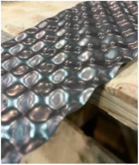
Figure 1.
The example of a bidirectionally sinusoidal corrugated steel plate [9].
1.3. Purpose and Scope of Work
The primary purpose of this study is to investigate the structural behaviour and performance characteristics of bidirectionally sinusoidal corrugated steel shells under static and dynamic loading. By leveraging finite element method (FEM) software, such as ABAQUS/CAE 2017 and RFEM 6.05 [20], this research aims to provide a compendious understanding of how these shells respond to considered loading conditions. Static analyses will be conducted to assess the shells’ strength and deformation under steady loads, while natural vibrations analyses will examine their dynamic properties and resonant frequencies. Dynamic analyses, including those involving repetitive loading scenarios, will offer deeper insights into the shells’ responses to fluctuating forces. Wirowski et al. (2016) demonstrated the importance of dynamic modelling in understanding the behaviour of structural elements under dynamic loads, providing valuable methodologies that inform this study [21,22].
The scope of this research encompasses several key objectives. Firstly, the research involves the development and implementation of numerical models of bidirectionally sinusoidal corrugated steel shells using the Python scripting features in ABAQUS and RFEM. Python scripting enables the automated generation of diverse model configurations, facilitating a systematic exploration of different geometrical and mechanical parameters that impact the structural responses of these elements. This approach not only enhances the efficiency of the model creation process, but also supports rapid iteration over the given list of parameters.
Secondly, the study includes a comparative analysis of the results obtained from ABAQUS and RFEM. This comparison evaluates the correctness of the numerical imitation of such a structure in each software to predict the subjected elements’ behaviour. In the following part of the study, only models created in ABAQUS are utilised.
Lastly, the investigation systematically explores the influences of different parameters on the performances of the considered elements. Diverse values of parameters such as corrugation amplitude, number of corrugation cells, and steel shell thickness are investigated in order to understand their effects on the structural responses of the subjected elements. These responses include deflections and maximum stresses in the static analysis and natural vibrations analysis, as well as deflections, velocities, accelerations, and stresses in the dynamic analysis. The findings from this analysis aim to provide insights into the optimal configurations of these elements.
By achieving these objectives, the study aims to advance the current understanding of bidirectionally sinusoidal corrugated steel shells. Through an in-depth analysis of various parameters, such as geometrical configurations, material properties, and dynamic loading conditions, this research provides novel insights into both the static and dynamic behaviour of these complex structures. The detailed parametric investigation not only highlights the intricate relationships between these factors, but also offers practical guidance for optimising design parameters to enhance structural performance. By addressing gaps in the existing literature, particularly in the area of dynamic response, this study contributes valuable and original knowledge to the field of structural engineering, paving the way for more efficient and effective uses of corrugated steel shells in a wide range of engineering applications.
2. Materials and Methods
2.1. Subject of the Analysis
The structural elements considered in this research are characterised by their unique geometry. Figure 2 presents the structural scheme of the elements that were imitated in the FEA software used. The element has a rectangular shape in a plane view, and its dimensions are described by Lx and Ly. The whole element is divided into identical periodic cells. In the X and Y axes’ directions, the element has nx and ny periodic cells, respectively. The dimensions of the one periodic cell are as follows: Lx/nx and Ly/ny. The whole part has a constant thickness t. The corrugation amplitude of the sinusoidal waves is also constant and described as f. The properties of the material are described as follows: Es as Young’s modulus, νs as Poisson’s ratio, and ρs as density. The assumed shell geometry of the analysed element can be described using Formula (1).
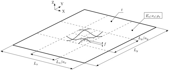
Figure 2.
The scheme of the elements analysed in this study with marked geometrical and material parameters.
Three different types of analyses were conducted. Boundary conditions, which refer to the constraints assumed in the numerical models, were identical for each of these analyses. The displacements of each edge of the element in each direction (ux, uy, and uz) were blocked, whereas the rotations (φx, φy, and φz) were not. The scheme of the numerically analysed element is shown in Figure 3.
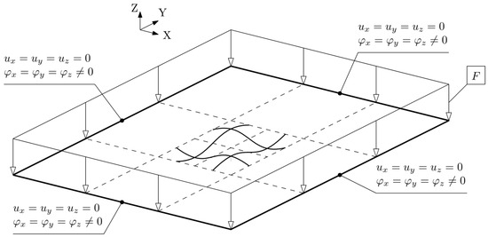
Figure 3.
The scheme of the elements analysed in this study with marked support conditions and applied force.
For these straightforward support conditions, it is reasonable to determine the deformation of the mid-plane of the plate utilising a differential equation, which is represented as:
This equation provides a mathematical framework for determining the deflection of the mid-plane under various loading conditions. For flat, non-corrugated, plates, the bending stiffness is defined as:
where h denotes the thickness of the plane element.
Similarly, for the analysis of natural frequencies and dynamic responses, despite the availability of known differential equations that can resolve such problems for flat plates (Formulas (4) and (5), respectively), determining a single bending stiffness value for a corrugated plate is impractical. Consequently, accurately capturing the complex behaviour of corrugated elements necessitates the use of numerical models that replicate the precise geometry of the structures.
The first analysis was the static analysis. It was performed in both the ABAQUS and RFEM software. In this analysis, a uniform load F was applied (Figure 4), opposite to the Z axis direction. Based on these results, the maximum deflection of the whole model and the global maximum value of von Mises stresses were obtained and then compared. A list of the parameters adopted for this analysis is presented in Table 1. The assumed number of various parameters resulted in a total of 360 combinations.

Table 1.
The values of the parameters adopted for the purpose of the static analysis and determining the dynamic properties (natural vibrations) of the subjected elements.
The second analysis concerned the natural vibrations of such steel shells. It was performed in both FEM software as well. The first ten natural frequencies and corresponding mode shapes were obtained. The same combinations of parameters as those in the static analysis described above were adopted for this analysis (Table 1).
Lastly, the dynamic analysis was conducted. It was performed only in the ABAQUS software. Not only was a uniform load F applied (Figure 4) to the corrugated steel shell, but the sinusoidal time function of this loading was also included. In the dynamic analysis, a time step of 0.000796 s was adopted, with a total analysis duration of 0.1592 s, resulting in 200 time steps. Based on the results, the maximum values of the displacements, velocities, and accelerations in the whole model and the global maximum values of von Mises stresses, all of them depending on time, were obtained. Table 2 presents the values of the parameters adopted for the dynamic analysis. The assumed number of various parameters resulted in a total of 32 combinations.
Table 2.
The values of the parameters adopted for the purpose of the dynamic analysis.
Additionally, in order to compare the results obtained from the ABAQUS and RFEM software, one comparative element was established. Table 3 presents the values of the parameters adopted for the comparative analyses.
Table 3.
The values of the parameters adopted for the purpose of the comparative analysis.
2.2. Software
2.2.1. ABAQUS
The primary software utilised in this study was ABAQUS/CAE 2017. Calculations were performed using the PLGrid Infrastructure, which provides access to clusters in five High-Performance Computing centres. Computational tasks were managed centrally through middleware that allocated resources across all hubs. For this analysis, the WCSS hub was used.
To model the bidirectionally sinusoidal corrugated steel elements, three-dimensional shell finite elements with 4 nodes and reduced integration, known as S4R, were employed. These were the conventional stress/displacement shell elements. After conducting a thorough convergence analysis for various mesh sizes, it was determined that a mesh with an element size of 0.005 m provided the optimal balance between computational efficiency and accuracy. This mesh size was chosen to ensure that the results were both precise and reliable, capturing the essential details of the structural behaviour without introducing unnecessary computational overhead.
The static analysis employed a direct method for solving the equation system, utilising the full Newton method as the solution technique. For the eigensolution method, the Lanczos method was chosen. Similarly, a nonlinear dynamic analysis (implicit dynamic analysis) was conducted using the direct method for solving the equation system. Damping was omitted in this analysis.
The use of Python scripting in ABAQUS significantly advanced the research by enabling the automated generation of a large number of models with various parameters. The utilisation of this feature can be found in the latest studies [23,24]. This automation greatly enhanced the efficiency and accuracy of the modelling process, allowing for a systematic exploration of bidirectionally sinusoidal corrugated steel shells with different geometrical and mechanical configurations. Python scripts were employed not only to create these models, but also to run simulations, which would be impractical to execute manually. Furthermore, the scripts were designed to extract specific results from the simulations, such as deflections, stresses, and dynamic responses. These results were then automatically saved into external text files, organised in a structured manner. This automated data extraction and storage facilitated an easy analysis and comparison of the results, ensuring that the data were consistently formatted and readily accessible for further processing. This approach not only streamlined the workflow, but also minimised the potential for manual errors, thereby improving the reliability and reproducibility of the study.
2.2.2. RFEM
The analyses in this study were also conducted using the RFEM software, version 6.05, specifically utilising the academic version on a standard mid-range laptop. Unlike ABAQUS, the dynamic analysis was not performed in RFEM due to the limitations of the software version used. However, RFEM was employed for the static and eigenvalue analyses, leveraging its capabilities to model and simulate the behaviour of bidirectionally sinusoidal corrugated steel shells.
In RFEM, the finite elements adopted for the analysis were combined shell elements (MITC, Mixed Interpolation of Tensorial Components, presented in Figure 4) and membrane elements with a mesh size of 0.005 m. The equation system solver for the static analysis employed the direct method, while the Newton–Raphson method was utilised as the solution technique. For the eigensolution method, the Lanczos method was chosen, similar to the approach used in ABAQUS.
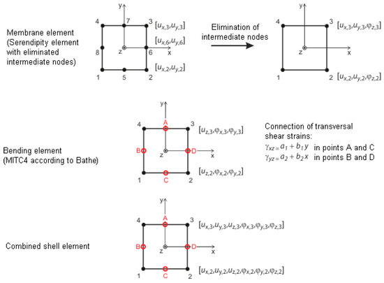
Figure 4.
The type of finite elements used for the analysis conducted in RFEM [25].
Python scripting played a crucial role in RFEM as well, particularly in generating the complex geometries of the bidirectionally sinusoidal corrugated steel elements. This automation facilitated the creation of detailed and precise models, allowing for an efficient and systematic exploration of different geometrical configurations. The use of Python in this context significantly streamlined the process, ensuring a high accuracy and consistency in the generated models.
3. Results
3.1. Static Analysis
3.1.1. Results Comparison
In this subsection, the deflections and maximum von Mises stresses obtained from ABAQUS and RFEM are compared for the previously established comparative element. Figure 5 shows the deflections obtained from a comparison of the results.
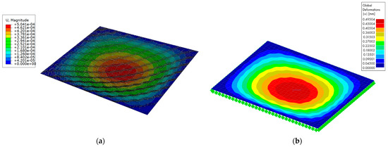
Figure 5.
The deflections of the comparative element obtained from: (a) ABAQUS (the unit of displacements is m) and (b) RFEM.
The shape of the deformation is almost the same, and the relative difference between the maximum values of deflections is equal to 1.8%.
Furthermore, the maximum values of von Mises stresses are presented in Figure 6.
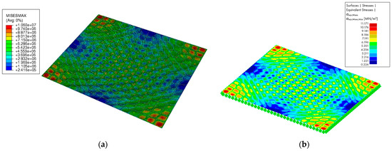
Figure 6.
The maximum von Mises stresses of the comparative element obtained from: (a) ABAQUS (the unit of stresses is Pa) and (b) RFEM.
It can be observed that the global maximum values of the stresses occur in the corners of the element—identically for both numerical models. Nonetheless, the relative difference in these values is quite higher than that for the displacements and is equal to 10.2%.
In the following subsections, the presented results are obtained from the models created in ABAQUS.
3.1.2. Deflections
Based on the obtained results, a series of graphs illustrating the relationship between the corrugation amplitude and maximum deflection of the element for various thicknesses of the steel sheet and the chosen number of periodic cells in each direction was created (Figure 7).
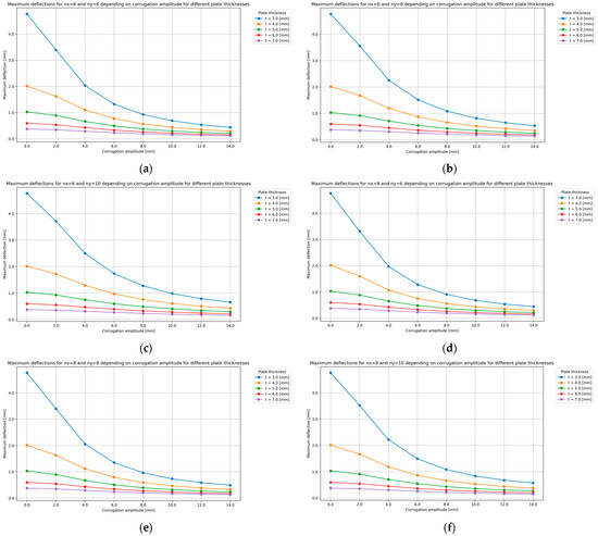
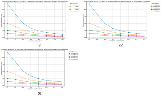
Figure 7.
The relationship between the corrugation amplitude and maximum deflection of the element for various thicknesses of the steel sheet and following number of periodic cells in each direction: (a) nx = 6, ny = 6; (b) nx = 6, ny = 8; (c) nx = 6, ny = 10; (d) nx = 8, ny = 6; (e) nx = 8, ny = 8; (f) nx = 8, ny = 10; (g) nx = 10, ny = 6; (h) nx = 10, ny = 8; and (i) nx = 10, ny = 10.
Furthermore, Figure 8 presents the relationship between the corrugation amplitude and maximum deflection of the element for various numbers of periodic cells in each direction and the chosen thickness of the steel sheet.
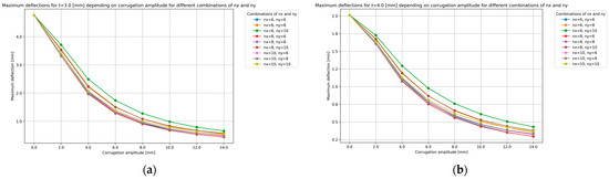
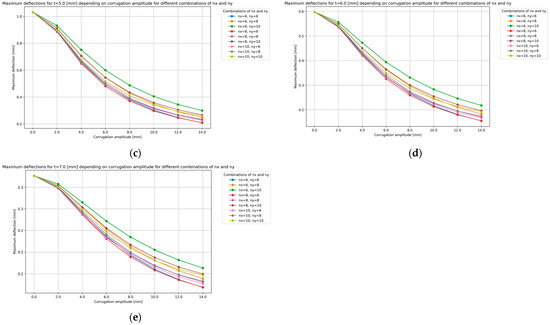
Figure 8.
The relationship between the corrugation amplitude and maximum deflection of the element for the various number of periodic cells in each direction and for following thicknesses of the steel sheet: (a) t = 3.0 mm; (b) t = 4.0 mm; (c) t = 5.0 mm; (d) t = 6.0 mm; and (e) t = 7.0 mm.
Lastly, a graph illustrating the relationship between the corrugation amplitude and maximum deflection of the element for various numbers of periodic cells in each direction and various thicknesses of the steel sheet was created and is shown in Figure 9. Each colour in the graph refers to each thickness of the steel sheet.
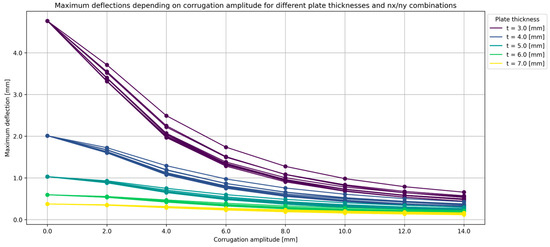
Figure 9.
The relationship between the corrugation amplitude and maximum deflection of the element for various numbers of periodic cells in each direction and various thicknesses of the steel sheet.
The analysis of the deflections in the corrugated steel sheets exposes several critical observations. It is noted that, while the configuration of the corrugation, specifically the various dimensions of the periodic cell, does not significantly impact the stiffening of the analysed element, the presence of corrugation itself plays a crucial role in enhancing stiffness. Among the different configurations, the square periodic cell emerges as the most optimal for this purpose.
A key finding is that, as the amplitude of the corrugation increases, the maximum deflection of the entire element decreases. This indicates that a greater corrugation amplitude contributes to an improved structural rigidity, effectively reducing the deflection under applied loads. Furthermore, the relative differences in deflections for elements with a given steel sheet thickness become more pronounced at higher corrugation amplitude-to-thickness ratios. This suggests that the benefits of an increased corrugation amplitude are more evident in thinner sheets, where the impact on deflection is more substantial.
Another important observation is the significant impact of corrugation on reducing deflections while maintaining structural performance. For instance, the maximum deflection of a flat plate with a thickness of 6 mm is nearly equal to the deflection of a corrugated element with a thickness of 3 mm and a corrugation amplitude of 14 mm. This comparison highlights that the process of folding can lead to a twofold reduction in mass without compromising the bending stiffness of the analysed element.
3.1.3. Stresses
Based on the obtained results, a series of graphs illustrating the relationship between the corrugation amplitude and maximum von Mises stress of the element for various thicknesses of the steel sheet and the chosen number of periodic cells in each direction was created (Figure 10).
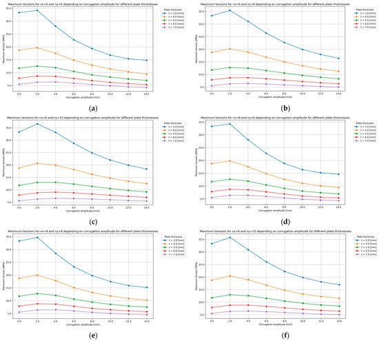
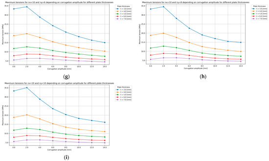
Figure 10.
The relationship between the corrugation amplitude and maximum von Mises stress of the element for various thicknesses of the steel sheet and the following number of periodic cells in each direction: (a) nx = 6, ny = 6; (b) nx = 6, ny = 8; (c) nx = 6, ny = 10; (d) nx = 8, ny = 6; (e) nx = 8, ny = 8; (f) nx = 8, ny = 10; (g) nx = 10, ny = 6; (h) nx = 10, ny = 8; and (i) nx = 10, ny = 10.
Furthermore, Figure 11 presents the relationship between the corrugation amplitude and maximum von Mises stress of the element for various numbers of periodic cells in each direction and the chosen thickness of the steel sheet.
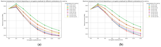
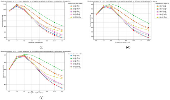
Figure 11.
The relationship between the corrugation amplitude and maximum von Mises stress of the element for various numbers of periodic cells in each direction and the following thicknesses of the steel sheet: (a) t = 3.0 mm; (b) t = 4.0 mm; (c) t = 5.0 mm; (d) t = 6.0 mm; and (e) t = 7.0 mm.
Lastly, a graph illustrating the relationship between the corrugation amplitude and maximum von Mises stress of the element for various numbers of periodic cells in each direction and for various thicknesses of the steel sheet was created and is shown in Figure 12. Each colour in the graph refers to each considered thickness of the steel sheet.
Figure 12.
The relationship between the corrugation amplitude and maximum von Mises stress of the element for various numbers of periodic cells in each direction and for various thicknesses of the steel sheet.
An analysis of the stress distribution in the corrugated steel sheets reveals several important insights. It is evident that, as the thickness of certain parts of the sheet decreases, there is a corresponding increase in the maximum values of the stresses. This is consistent with the general understanding that thinner materials are less capable of distributing and withstanding applied loads, leading to higher stress concentrations.
This study observes that, for small corrugation amplitudes, the maximum value of the von Mises stress initially increases. This suggests that minor corrugation does not sufficiently enhance structural rigidity, thereby failing to mitigate stress effectively. However, as the amplitude of the corrugation continues to increase, a notable trend emerges. Beyond a specific corrugation amplitude threshold, the maximum von Mises stress begins to decrease. This correlation indicates that larger corrugation amplitudes significantly improve the structural integrity of the sheet, thereby reducing the maximum stresses experienced.
A similar pattern is observed with deflections, where the relative change in maximum stresses becomes more pronounced as the thickness of the steel sheet decreases. Thinner sheets demonstrate a higher sensitivity to variations in corrugation amplitude, leading to more significant changes in stress distribution.
Moreover, the geometric configuration of the corrugation plays a crucial role in stress distribution. The study finds that square periodic cells are the most effective in reducing maximum stress values. In contrast, more rectangular cells result in a lower reduction in stress, indicating that the shape and periodicity of the corrugation significantly influence the stress mitigation capabilities of the sheet.
3.2. Natural Vibrations
3.2.1. Results Comparison
In this subsection, the natural frequencies and mode shapes obtained from ABAQUS and RFEM are compared for the previously established comparative element. Figure 13 shows the first six mode shapes obtained from the results.
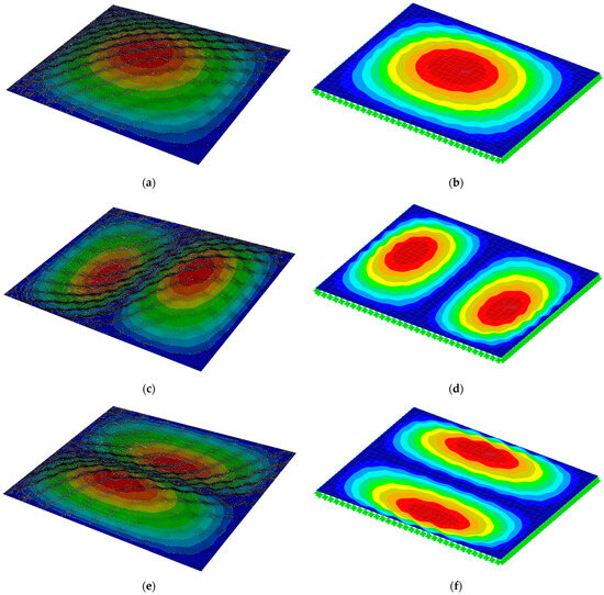
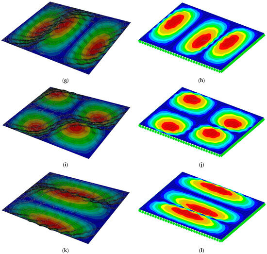
Figure 13.
The first six mode shapes obtained from ABAQUS and RFEM: (a) first mode shape (ABAQUS); (b) first mode shape (RFEM); (c) second mode shape (ABAQUS); (d) second mode shape (RFEM); (e) third mode shape (ABAQUS); (f) third mode shape (RFEM); (g) fourth mode shape (ABAQUS); (h) fourth mode shape (RFEM); (i) fifth mode shape (ABAQUS); (j) fifth mode shape (RFEM); (k) sixth mode shape (ABAQUS); and (l) sixth mode shape (RFEM). Note: red colour indicates the greatest deflection from the base position, while the blue colour indicates the smallest one.
Furthermore, the obtained natural frequencies from both models and their comparison, including their relative differences (calculated using Formula (6)), are shown in Table 4.
Table 4.
The comparison of the natural frequencies obtained from ABAQUS and RFEM.
For each natural frequency presented, the relative differences obtained from the results are negligibly small.
In the following subsection, the presented results are obtained from the models created in ABAQUS.
3.2.2. Natural Frequencies
Based on the obtained results, a graph presenting the relationship between the corrugation amplitude and value of the first six natural frequencies for various numbers of periodic cells in each direction and various thicknesses of the steel sheet was created (Figure 14). Each colour in the graph refers to each considered thickness of the steel sheet.
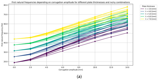
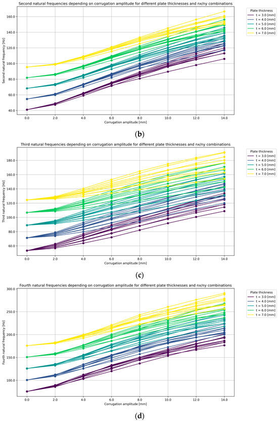
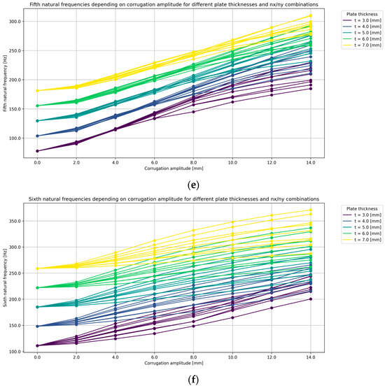
Figure 14.
The relationship between the corrugation amplitude and value of a chosen natural frequency for various numbers of periodic cells in each direction and for various thicknesses of the steel sheet: (a) first natural frequency; (b) second natural frequency; (c) third natural frequency; (d) fourth natural frequency; (e) fifth natural frequency; and (f) sixth natural frequency.
An analysis of natural vibration frequencies reveals distinct patterns based on the mode shapes of the vibrations, which sometimes resemble the structures of the elements themselves. Depending on the arrangement of nodal lines, the analysed elements can be more susceptible to certain frequencies. This susceptibility highlights the influence of the nodal line configuration on the vibrational behaviour of the elements.
Considering that the folding process stiffens the elements, it is observed that, with an increasing amplitude of corrugation, the natural vibration frequencies also increase. This relationship indicates that, as the structural stiffness is enhanced through a greater corrugation amplitude, the ability of the element to resist vibrational motion improves, resulting in higher frequencies of natural vibrations.
Moreover, the relative differences in the obtained natural vibration frequencies do not converge as closely as observed in the cases of deflections or stresses. This suggests that the impact of corrugation on natural frequencies is more variable and dependent on the specific geometric and material properties of the elements. Consequently, the variations in frequency values are more pronounced, underscoring the complex interaction between the structural configuration and its dynamic response.
3.3. Dynamic Analysis
3.3.1. Deflections
In this subsection, the deflection results over time from the dynamic analysis are presented. Figure 15 shows the relationship between the corrugation amplitude and the maximum deflection of the element over a given period of time for the considered thicknesses of a steel sheet.
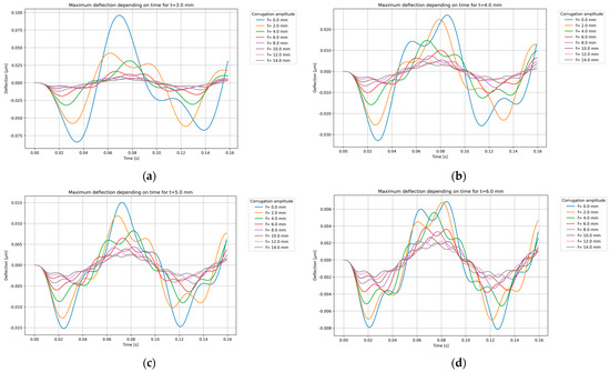
Figure 15.
The relationship between the corrugation amplitude and the maximum deflection of the element over a given period of time for the chosen thickness of a steel sheet: (a) t = 3.0 mm; (b) t = 4.0 mm; (c) t = 5.0 mm; and (d) t = 6.0 mm.
The analysis of the graphs yields several significant conclusions. Firstly, thinner sheets exhibit a greater relative gain in stiffness for a given corrugation (the same result might be observed in static analysis). This indicates that corrugation is particularly effective in enhancing the structural performance of thinner plates, resulting in more pronounced deflection reductions compared to thicker plates.
Additionally, the graphs reveal the superposition of two waves—one associated with the external forcing and the other with the natural frequency of the plates. The forcing wave remains consistent over time, while the natural wave exhibits variability. This superposition indicates a complex dynamic interaction, where the constant frequency of the external force interacts with the variable natural frequency of the corrugated plates, influencing the overall deflection behaviour.
Moreover, for certain values of corrugation, the relative differences in deflections begin to diminish. This suggests that there is an optimal range of corrugation, beyond which, further increases in corrugation amplitude yield diminishing returns in terms of deflection reduction.
3.3.2. Velocities
Based on the results obtained from the dynamic analysis, the velocities over a considered time period were also determined. The relationship between the corrugation amplitude and the maximum velocity of the element over a given period of time for the considered thicknesses of a steel sheet is shown in Figure 16.
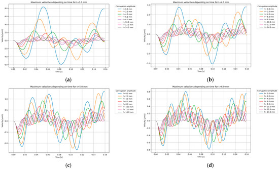
Figure 16.
The relationship between the corrugation amplitude and the maximum velocity of the element over a given period of time for the chosen thickness of a steel sheet: (a) t = 3.0 mm; (b) t = 4.0 mm; (c) t = 5.0 mm; and (d) t = 6.0 mm.
The analysis of dynamic velocity over time for plates of various thicknesses and corrugations reveals several insights similar to those observed in the deflection analysis. Firstly, as shown with the static analysis, thinner sheets demonstrate a greater relative gain in performance for a given corrugation.
Secondly, the graphs also show the superposition of two waves—one associated with external forcing and the other with the natural frequency of the plates.
A key observation in reference to the velocity analysis is that, beyond a certain corrugation amplitude, the differences in velocity responses become less pronounced. This suggests that there is a threshold of corrugation, beyond which, further increases in amplitude do not significantly impact the dynamic velocity of the plates.
3.3.3. Accelerations
The results obtained from the dynamic analysis also included the accelerations over a considered time period. The relationship between the corrugation amplitude and the maximum acceleration of the element over a given period of time for the considered thicknesses of a steel sheet is shown in Figure 17.
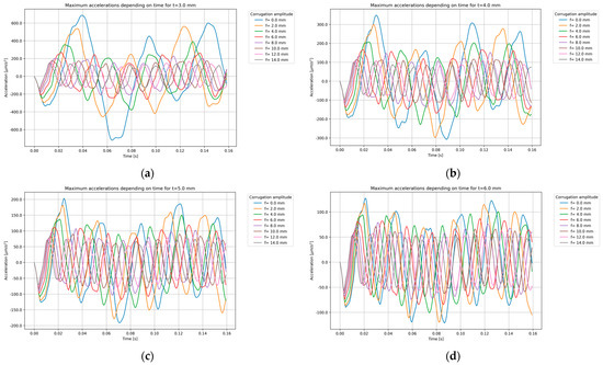
Figure 17.
The relationship between the corrugation amplitude and the maximum acceleration of the element over a given period of time for the chosen thickness of a steel sheet: (a) t = 3.0 mm; (b) t = 4.0 mm; (c) t = 5.0 mm; and (d) t = 6.0 mm.
The analysis of the dynamic acceleration over time for plates of various thicknesses and corrugations provides several important observations. Firstly, it is noted that, for thicker plates, the differences in acceleration due to various corrugations become less pronounced. This suggests that an increased plate thickness diminishes the impact of corrugation on dynamic acceleration, making these differences less noticeable.
Furthermore, the graphs indicate that higher natural vibration frequencies result in a greater density of oscillations on the acceleration plots. This means that, as the natural frequency of the corrugated plates increases, the frequency of the acceleration waveforms becomes more tightly packed, reflecting the more rapid changes in acceleration experienced by the plates.
A significant finding from the analysis is that, compared to deflection and velocity, the effect of corrugation on acceleration is the least pronounced. While corrugation substantially influences deflections and velocities, its impact on accelerations is relatively minimal. This suggests that, while corrugation enhances overall structural performance, its benefits are more pronounced in terms of reducing deflections and velocities rather than accelerations.
3.3.4. Stresses
The values of the von Mises stresses in the whole model were also determined. Only the maximum values in each time step over a considered time period were collected. The relationship between the corrugation amplitude and the maximum von Mises stress of the element over a given period of time for the considered thicknesses of a steel sheet is shown in Figure 18.
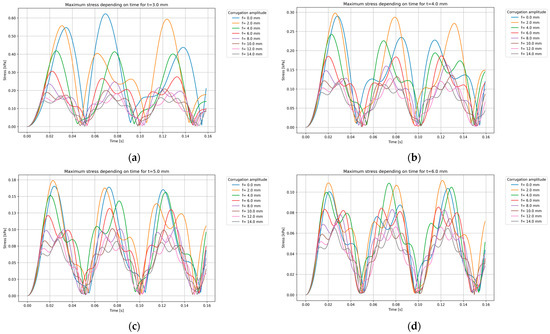
Figure 18.
The relationship between the corrugation amplitude and the maximum von-Mises stress of the element over a given period of time for the chosen thickness of a steel sheet: (a) t = 3.0 mm; (b) t = 4.0 mm; (c) t = 5.0 mm; and (d) t = 6.0 mm.
The analysis of the maximum stress over time for plates of various thicknesses and corrugations reveals several key insights. Firstly, it is evident, as in the static analysis, that thicker elements experience lower absolute stresses. This finding aligns with the fundamental understanding that an increased material thickness enhances the ability to distribute and withstand applied loads, thereby reducing stress concentrations.
Additionally, the analysis indicates that larger corrugation amplitudes also contribute to stress reduction, similar to the effects observed in static conditions. Larger waves in the corrugated structure enhance the stiffness and load-bearing capacity, leading to a decrease in the maximum stress values over time. However, this stress reduction effect has a limit. Beyond a certain corrugation amplitude, further increases do not result in noticeable decreases in stress, indicating a threshold that, beyond which, additional corrugation would provide minimal, if any, further benefit.
4. Summary
Bidirectionally sinusoidal corrugated steel shell structures represent a versatile and compelling choice in modern engineering and architectural applications. These structures, characterised by their folded configurations, offer unique advantages such as an enhanced stiffness, efficient material usage, and aesthetic flexibility. The research presented in this paper aimed to deepen our understanding of the behaviour of such elements, focusing on both numerical modelling validation and detailed performance analyses.
The initial focus of this study was to validate the methodology used for generating folds in numerical models, implemented in RFEM and ABAQUS. This validation process was crucial in establishing reliable and accurate simulations that could replicate real-world behaviour. The results showed that the method of creating waves in RFEM caused slightly greater values of the stresses due to the lack of a smooth transition between the components of the whole element. The feature of creating a regular wave, which is available in ABAQUS, allows for omitting this issue. Nonetheless, both models were sufficient to represent an enhanced stiffness of the subjected element, which could be observed in deflections and natural vibrations.
One of the primary findings concerned the sensitivity of corrugated steel structures to steel sheet thickness. The research demonstrated that thinner sheets exhibited a more significant influence of the corrugation amplitude on the deflections and stresses. A critical parameter highlighted in this paper was the height-to-thickness ratio of corrugated steel sheets, where the height represents the corrugation amplitude. This parameter not only affects stiffness and load-bearing capacity, but also influences the overall efficiency of material usage in structural applications. Although the research showed that the higher the mentioned ratio was, the more efficient solution it provided, it has to be highlighted that the analysed element might lose its properties if the ratio of the corrugation amplitude to the smallest dimension of the corrugation cell is excessive. In this study, the highest value of this ratio was equal to 0.1475. The analysis concerning this issue was not the subject of this paper, and might be a relevant aspect to be consider in future research.
Furthermore, the study delved into the impact of folding methods, particularly the configurations of corrugations (number of waves in each direction), on the static and dynamic characteristics of the considered structures. It was observed that these configurations influenced displacements, stresses, and natural vibration frequencies, however, the impact was not substantial. It could be stated that, in terms of design optimisation, the research identified nearly square corrugation cells as being optimal for stiffening steel sheets by bidirectionally sinusoidal corrugation. This finding provides practical guidance for future research by strongly suggesting a minor impact of these parameters.
The dynamic analyses conducted in this study revealed that thinner sheets showed greater performance gains with an increasing corrugation amplitude, reducing deflections, velocities, and stresses. The superposition of forcing and natural frequency waves indicated complex dynamic interactions. Higher natural frequencies led to denser oscillations in acceleration plots, while thicker elements exhibited less variation in acceleration due to corrugation. Additionally, larger corrugation amplitudes reduced stresses up to a certain threshold, beyond which, further increases offered minimal benefit. These findings underscore the importance of optimising corrugation parameters to effectively enhance structural performance, with the most notable impacts seen in deflection and velocity reductions.
Despite the structural stiffening effect of corrugation, the study noted that the nodal lines maintained their geometric integrity, allowing for the creation of complex forms through bending and facilitating the integration of additional steel elements. This inherent flexibility enhances the architectural and engineering possibilities of corrugated steel sheet structures, enabling innovative designs that combine structural efficiency with aesthetic appeal.
5. Conclusions and Future Research
Based on the results obtained in this study, several key conclusions can be drawn that guide the direction of future research. Investigations into the structural behaviour of bidirectionally sinusoidal corrugated steel shells under static and dynamic loading provide valuable insights into their performance, including the influence of various geometrical and mechanical parameters on their deformation, stress distribution, and dynamic properties. These findings establish a solid foundation for further exploration, paving the way for more detailed analyses and the potential application of these elements in engineering practice. The following paragraphs outline the primary areas of focus for future research, building on the outcomes of this study to enhance the understanding and application of corrugated steel shell structures.
Future research will prioritise several key areas to advance our understanding and propose possible applications for bidirectionally sinusoidal corrugated steel shells. Firstly, there will be a focus on assessing the feasibility and benefits of replacing ribbed steel sheets with corrugated steel sheets in industrial structures. This analysis aims to highlight potential improvements in structural performance, cost effectiveness, and overall efficiency.
Secondly, optimisation methods will be extensively employed to determine the optimal values of key parameters, aiming to reduce material usage and construction costs while maintaining or enhancing structural integrity. These efforts will involve refining existing design methodologies and exploring innovative approaches to optimise the design and fabrication processes.
Furthermore, there will be a comprehensive exploration of the dynamic behaviour of these elements under various loading conditions, including technological, temperature, and wind loads. This research will enhance our understanding of how these structures perform and inform strategies for enhancing their resilience and performance in real-world applications.
Another critical area of investigation will be to perform an analysis concerning the relationship of the height-to-thickness ratio of the subjected element. Innovative design methodologies will be developed to leverage advanced computational tools like neural networks and generative algorithms. These methodologies will contribute to optimising structural configurations, pushing the boundaries of efficiency and performance in the subjected elements. It will aim to establish guidelines for selecting the optimal sheet profiles that balance structural efficiency with material usage, contributing to more sustainable construction practices.
One of the key aspects that future research will be focused on is identifying effective strength parameters that allow for representations of the analysed elements using orthotropic plate models, given the repetitive structure of the studied elements. Developing these orthotropic models is crucial for determining precise values for stiffness, strength, and other relevant mechanical properties to reliably mimic the behaviour of corrugated steel sheets. Effective orthotropic models will significantly reduce computational expenses by simplifying complex three-dimensional analyses into more manageable two-dimensional simulations. This reduction in computational load will enable more efficient and extensive studies of these structures, accelerating the design process. Furthermore, the development of such models will provide a compelling argument for the broad application of corrugated steel elements in structural design. It will demonstrate the feasibility of using these efficient, reliable, and computationally optimised models in various engineering projects, facilitating the integration of corrugated steel sheets into a wide range of applications and promoting their adoption in both traditional and innovative construction practices.
Finally, collaboration with industry partners will be crucial for validating research findings and implementing solutions in practical applications. This collaborative approach will ensure that research outcomes translate effectively into real-world projects, addressing industry needs and advancing the adoption of corrugated steel sheet structures across various sectors.
In conclusion, future research will aim to expand the knowledge about the potential application and benefits of bidirectionally sinusoidal corrugated steel shell structures across diverse engineering and architectural domains. Through rigorous analysis, parameter optimisation, and the determination of engineering guidelines, this will contribute to the evolution of modern structural engineering practices.
Author Contributions
Conceptualisation, A.W., M.R., and D.K.; methodology, A.W. and D.K.; software, D.K.; validation, D.K.; investigation, D.K.; data curation, D.K.; writing—original draft preparation, D.K.; writing—review and editing, A.W. and M.R; visualisation, D.K.; supervision, A.W. and M.R. All authors have read and agreed to the published version of the manuscript.
Funding
This research received no external funding.
Institutional Review Board Statement
Not applicable.
Informed Consent Statement
Not applicable.
Data Availability Statement
The data presented in this study are available on request from the corresponding author.
Conflicts of Interest
The authors declare no conflicts of interest.
References
- Oval, R.; Rippmann, M.; Mensil, R.; Van Mele, T.; Baverel, O.; Block, P. Feature-based topology finding of patterns for shell structures. Autom. Constr. 2019, 103, 185–201. [Google Scholar] [CrossRef]
- Sokołowski, D.; Kamiński, M. Some Reliability Issues of the Corrugated I-Beam Girder. Eng. Trans. 2015, 63, 297–315. [Google Scholar]
- Sokołowski, D.; Kamiński, M. Stochastic Finite Element Method SORM study of the corrugated web steel plate girder. In Advances in Mechanics: Theoretical, Computational and Interdisciplinary Issues—3rd Polish Congress of Mechanics, PCM 2015 and 21st International Conference on Computer Methods in Mechanics, CMM 2015; CRC Press: Boca Raton, FL, USA, 2016; pp. 529–532. [Google Scholar]
- Sokołowski, D.; Kamiński, M. Reliability analysis of the corrugated web I girder under corrosion or fire by the Stochastic Finite Element Method and SORM. In Proceedings of the 12th International Conference on Structural Safety & Reliability, Vienna, Austria, 6–10 August 2017. [Google Scholar]
- Kiymaz, G.; Coskun, E.; Cosgun, C.; Seckin, E. Transverse load carrying capacity of sinusoidally corrugated steel web beams with web openings. Steel Compos. Struct. 2010, 10, 69–85. [Google Scholar] [CrossRef]
- Feng, L.; Sun, T.; Ou, J. Method of determining the minimum number of stiffeners for stiffened corrugated steel walls. Structures 2021, 34, 3487–3500. [Google Scholar] [CrossRef]
- Eldib, M.-H. Shear buckling strength and design of curved corrugated steel webs for bridges. J. Constr. Steel Res. 2009, 65, 2129–2139. [Google Scholar] [CrossRef]
- Perliński, W. Stateczność Jedno oraz Dwukierunkowo Wstępnie Pofałdowanych Sinusoidalnie Ścianek Kształtowników Stalowych. Doctoral Thesis, Lodz University of Technology, Łódź, Poland, 2017. [Google Scholar]
- Gajdzicki, M.; Perliński, W.; Michalak, B. Stability analysis of bi-directionally corrugated steel plates with orthotropic plate model. Eng. Struct. 2018, 160, 519–534. [Google Scholar] [CrossRef]
- Sun, H.J.; Guo, Y.L.; Wen, C.B.; Zuo, J.Q.; Zhao, Q.; Liu, Z.G. The strength design of deeply buried circular corrugated steel arches with considering only soil radial restraining. Thin-Walled Struct. 2023, 183, 110422. [Google Scholar] [CrossRef]
- Chen, W.; Yang, J.S.; Wei, D.Y.; Yan, S.T.; Peng, L.X. Buckling analysis of corrugated-core sandwich plates using a FSDT and a meshfree Galerkin method. Thin-Walled Struct. 2022, 180, 109846. [Google Scholar] [CrossRef]
- Zhang, Y.; Chen, Y.; Yun, L.; Liang, X. Mechanical Performance of Bio-inspired Bidirectional Corrugated Sandwich Pressure Shell Under External Hydrostatic Pressure. China Ocean. Eng. 2024, 38, 297–312. [Google Scholar] [CrossRef]
- Le, V.T.; Goo, N.S. Thermomechanical performance of bio-inspired corrugated-core sandwich structure for a thermal protection system panel. Appl. Sci. 2019, 9, 5541. [Google Scholar] [CrossRef]
- Xia, F.; Durandet, Y.; Tan, P.; Ruan, D. Three-point bending performance of sandwich panels with various types of cores. Thin-Walled Struct. 2022, 179, 109723. [Google Scholar] [CrossRef]
- Hammarberg, S.; Kajberg, J.; Larsson, S.; Jonsén, P. Ultra high strength steel sandwich for lightweight applications. SN Appl. Sci. 2020, 2, 1040. [Google Scholar] [CrossRef]
- Yang, X.; Ma, J.; Shi, Y.; Sun, Y.; Yang, J. Crashworthiness investigation of the bio-inspired bi-directionally corrugated core sandwich panel under quasi-static crushing load. Mater. Des. 2017, 135, 275–290. [Google Scholar] [CrossRef]
- Zhang, Z.; Lei, H.; Xu, M.; Hua, J.; Li, C.; Fang, D. Out-of-plane compressive performance and energy absorption of multi-layer graded sinusoidal corrugated sandwich panels. Mater. Des. 2019, 178, 107858. [Google Scholar] [CrossRef]
- Che, Q.; Xu, P.; Li, Z.; Ma, W.; Yao, S. Crashworthiness analysis of a multi-layered bi-directionally corrugated steel plates structure. Sci. Prog. 2020, 103. [Google Scholar] [CrossRef] [PubMed]
- Le, V.T.; Goo, N.S. Design, fabrication, and testing of metallic thermal protection systems for spaceplane vehicles. J. Spacecr. Rockets 2021, 58, 1043–1060. [Google Scholar] [CrossRef]
- RFEM 6. Available online: https://www.dlubal.com/en/downloads-and-information/documents/online-manuals/rfem-6?srsltid=AfmBOorHKsSYyHcn8Dmj12nl2OwczsmRsu3mtdUSk539fz6GzPoVIzLT (accessed on 21 August 2024).
- Wirowski, A.; Michalak, B.; Rabenda, M. The Dynamic Modelling of Thin Skeletonal Annular Plates. Contin. Media Microstruct. 2016, 2, 397–418. [Google Scholar]
- Wirowski, A.; Michalak, B.; Gajdzicki, M. Dynamic Modelling of Annular Plates of Functionally Graded Structure Resting on Elastic Heterogeneous Foundation with Two Modules. J. Mech. 2015, 31, 493–504. [Google Scholar] [CrossRef]
- Kowalczyk, I.; Kozanecki, D.; Krasoń, S.; Rabenda, M. Computational Modelling of VIG Plates Using FEM: Static and Dynamic Analysis. Materials 2022, 15, 1467. [Google Scholar] [CrossRef] [PubMed]
- Kozanecki, D.; Kowalczyk, I.; Krasoń, S.; Rabenda, M.; Domagalski, Ł.; Wirowski, A. The Machine Learning Methods in Non-Destructive Testing of Dynamic Properties of Vacuum Insulated Glazing Type Composite Panels. Materials 2023, 16, 5055. [Google Scholar] [CrossRef]
- Finite Elements in RFEM. Available online: https://www.dlubal.com/en/downloads-and-information/documents/online-manuals/rfem-6/000434 (accessed on 29 June 2024).
Disclaimer/Publisher’s Note: The statements, opinions and data contained in all publications are solely those of the individual author(s) and contributor(s) and not of MDPI and/or the editor(s). MDPI and/or the editor(s) disclaim responsibility for any injury to people or property resulting from any ideas, methods, instructions or products referred to in the content. |
© 2024 by the authors. Licensee MDPI, Basel, Switzerland. This article is an open access article distributed under the terms and conditions of the Creative Commons Attribution (CC BY) license (https://creativecommons.org/licenses/by/4.0/).