

Non-Destructive Cyclic Analysis of Sealing Ability of Well Cement for Seasonal Underground Hydrogen Storage

 , , ,
, , ,
Abstract
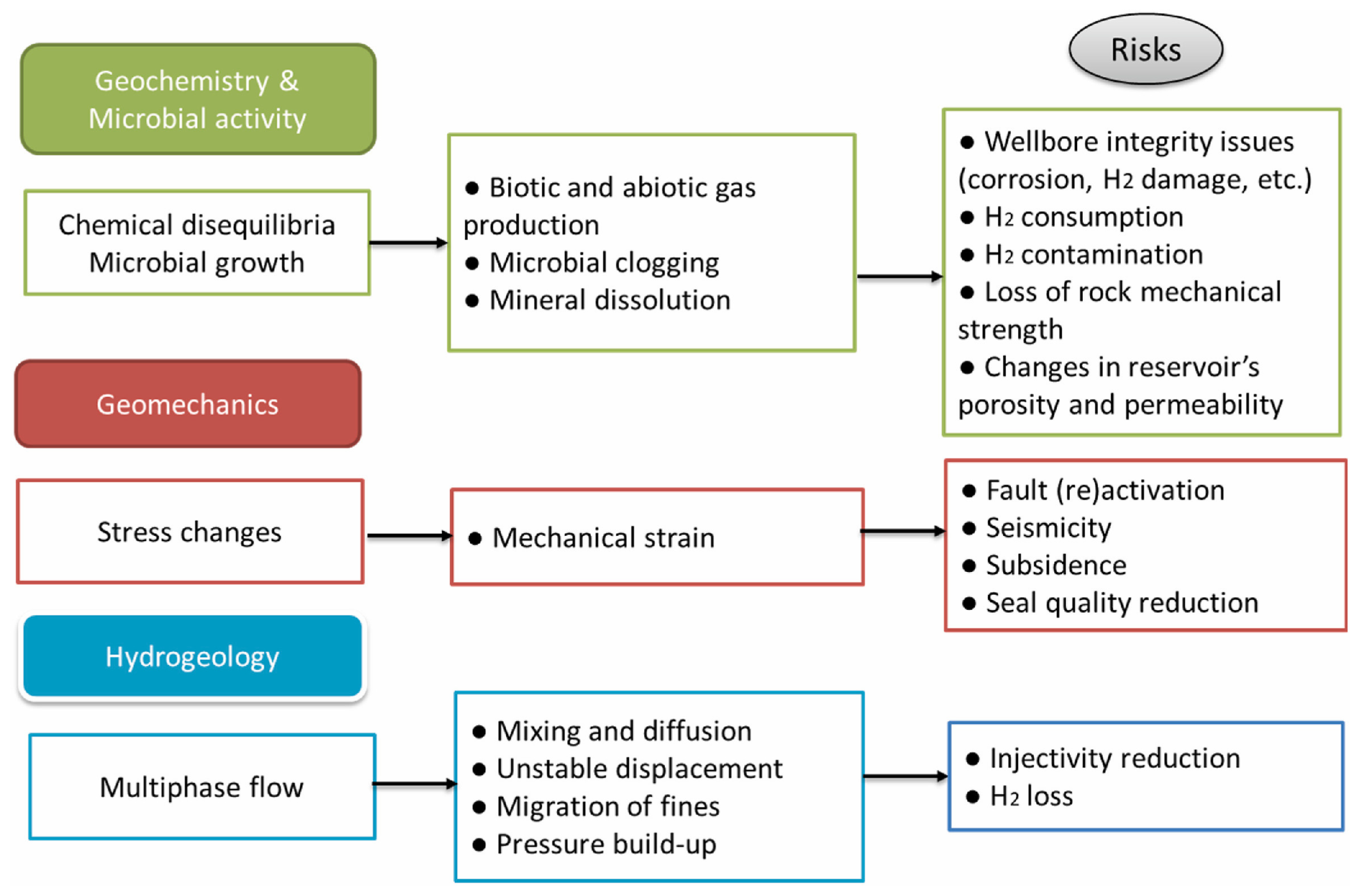
1. Introduction
2. Materials and Methods
2.1. Materials
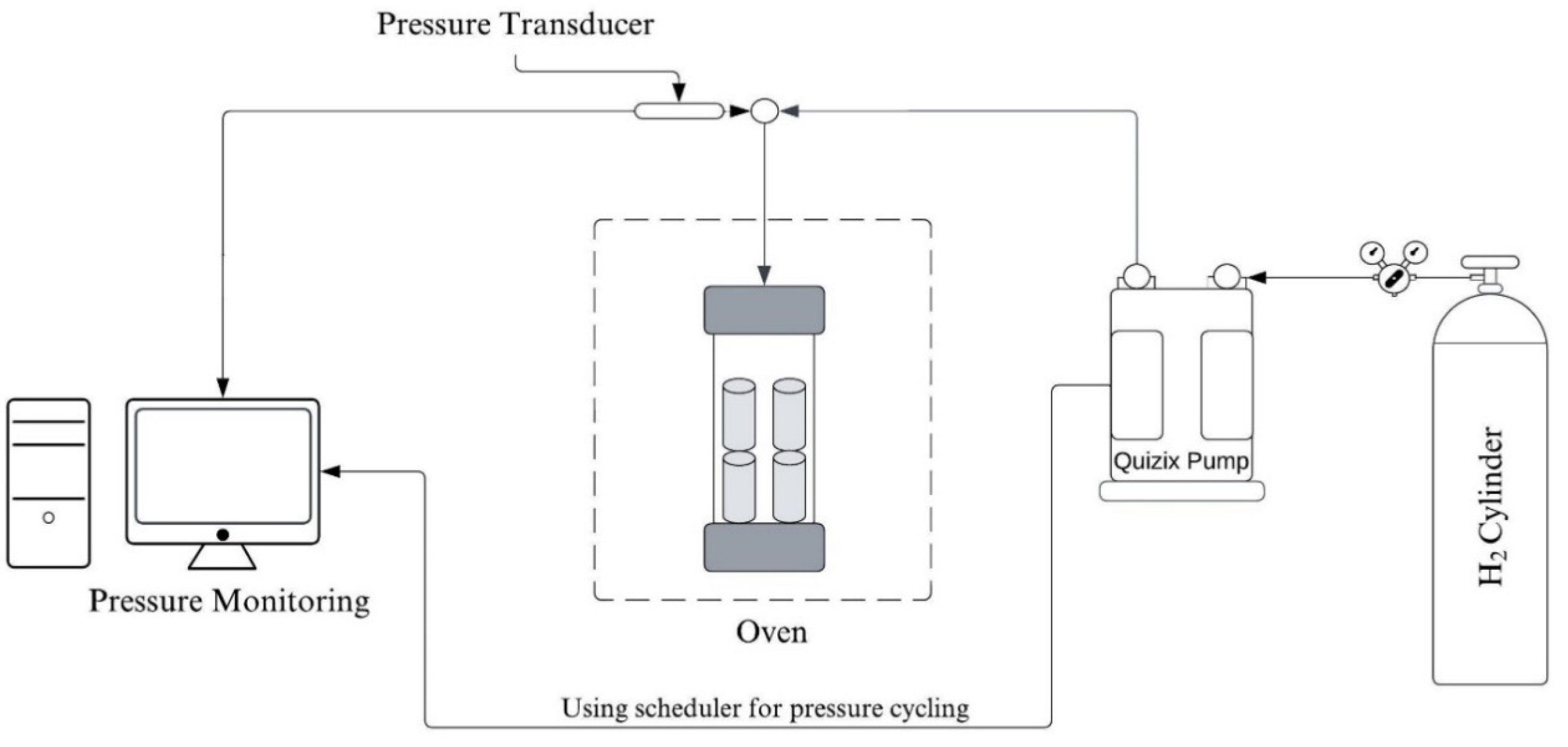
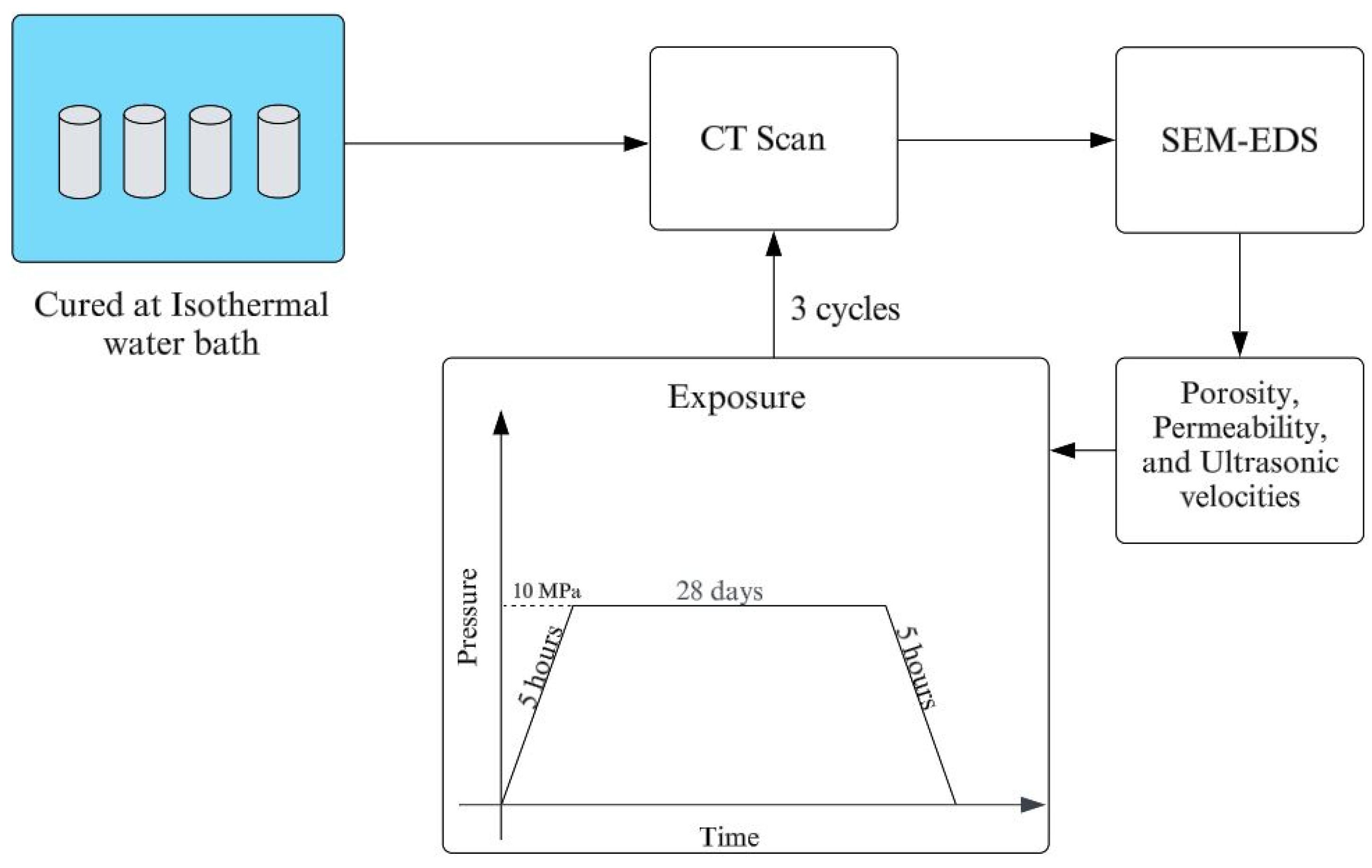
2.2. Methods
2.2.1. Porosity and Permeability Measurement
2.2.2. Dynamic Elastic Property Measurement
2.2.3. SEM-EDS Analyses
3. Results and Discussion
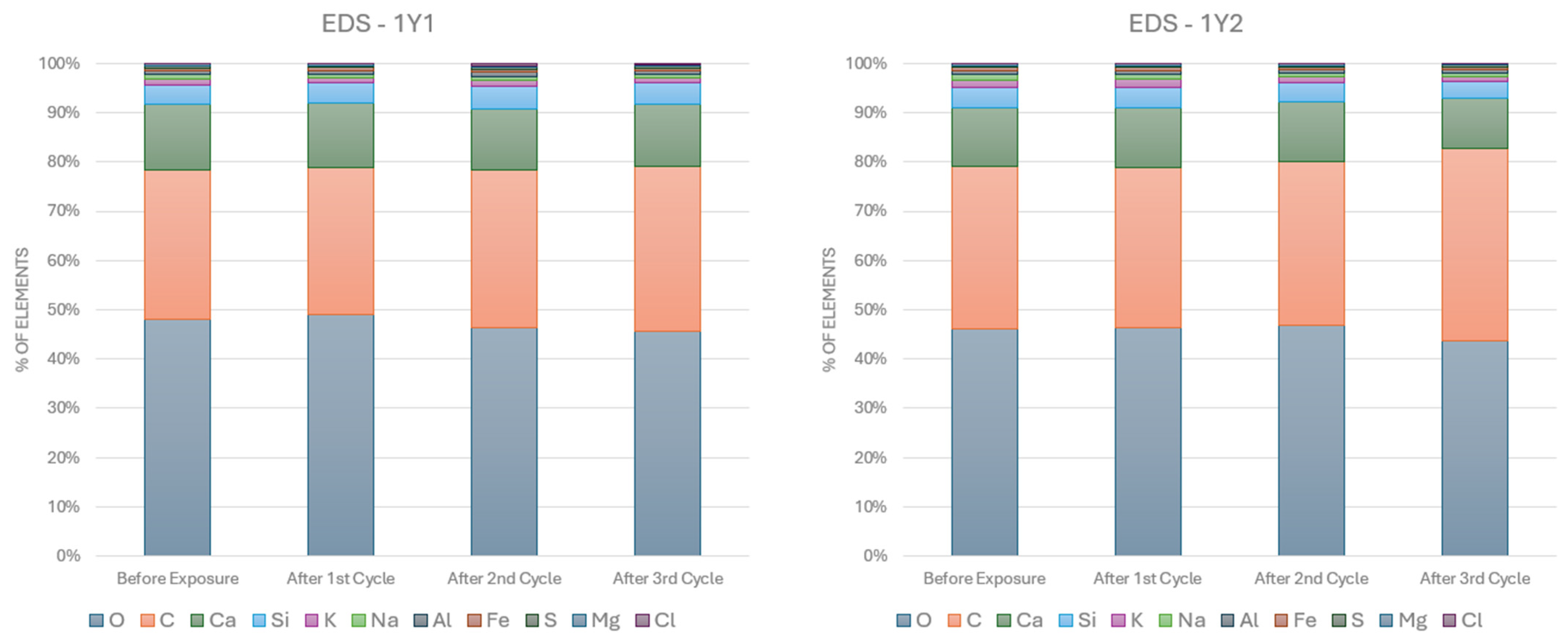
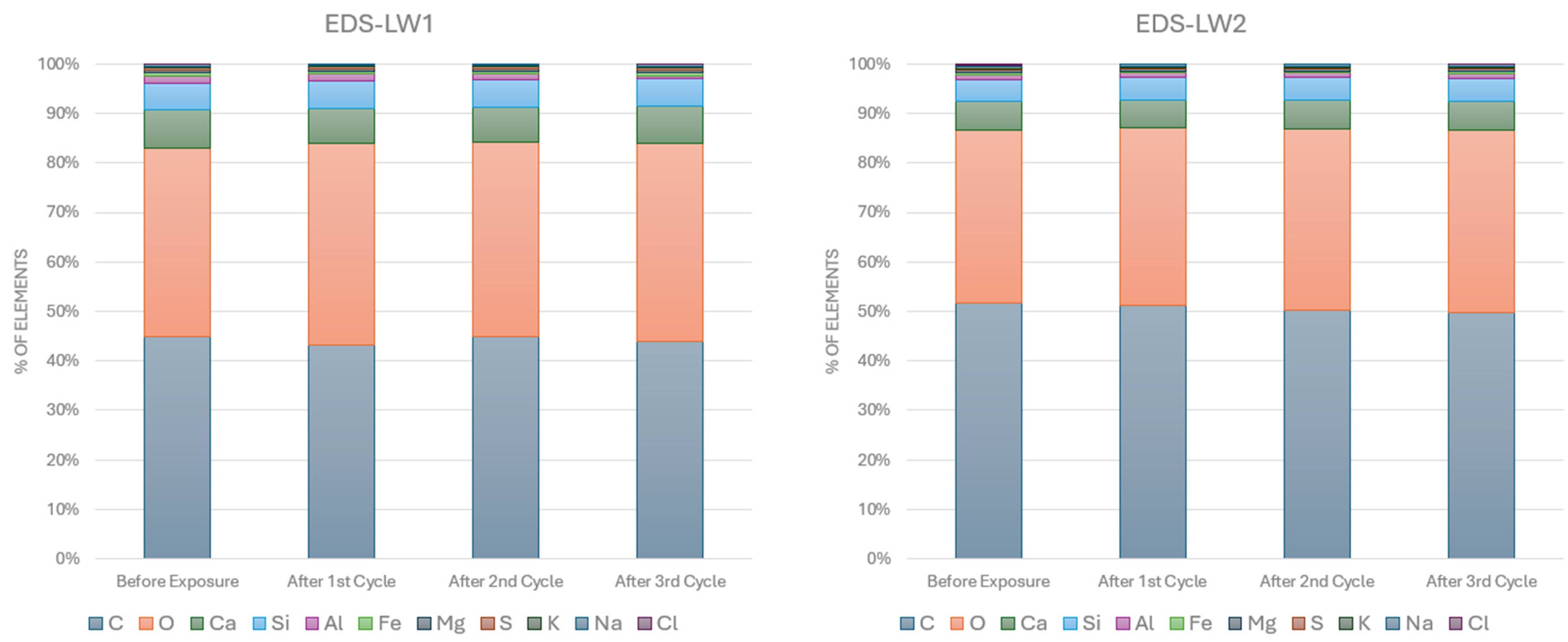
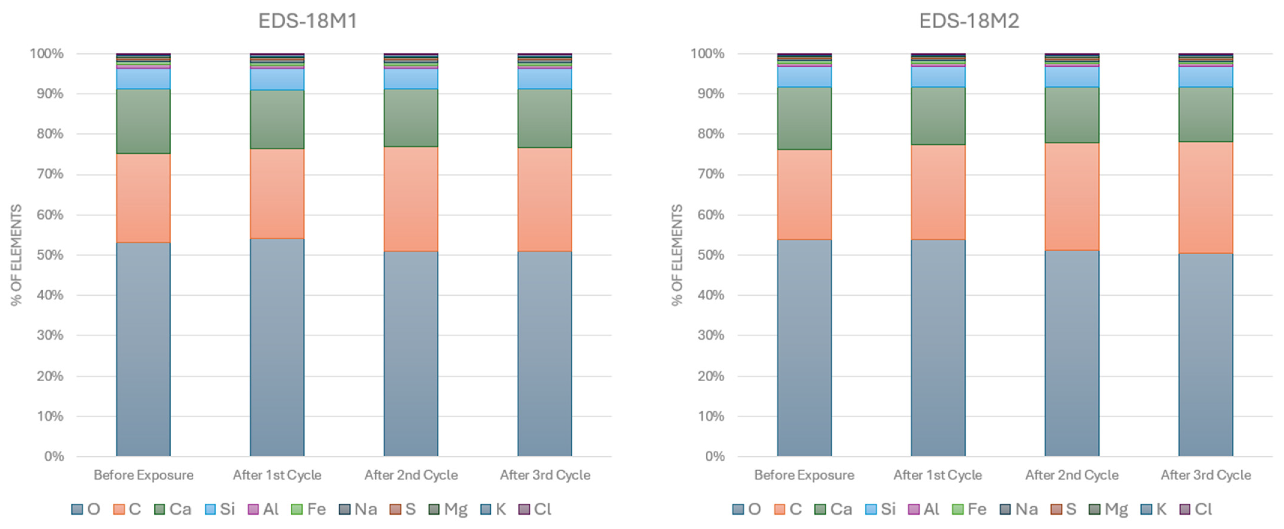
3.1. SEM-EDS Analyses
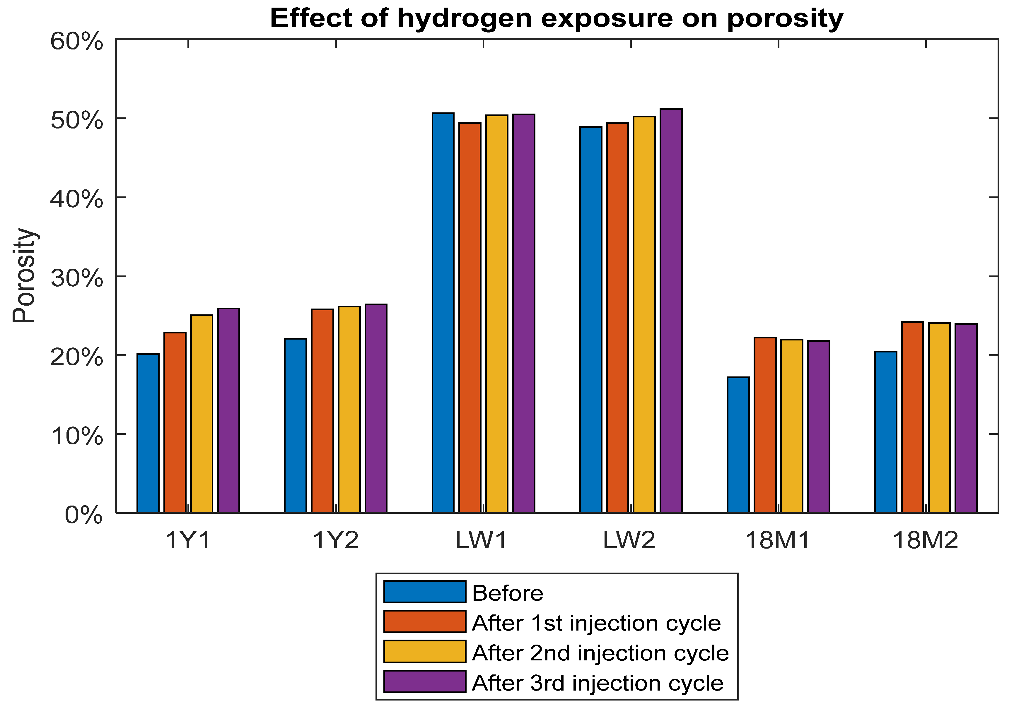
3.2. Porosity
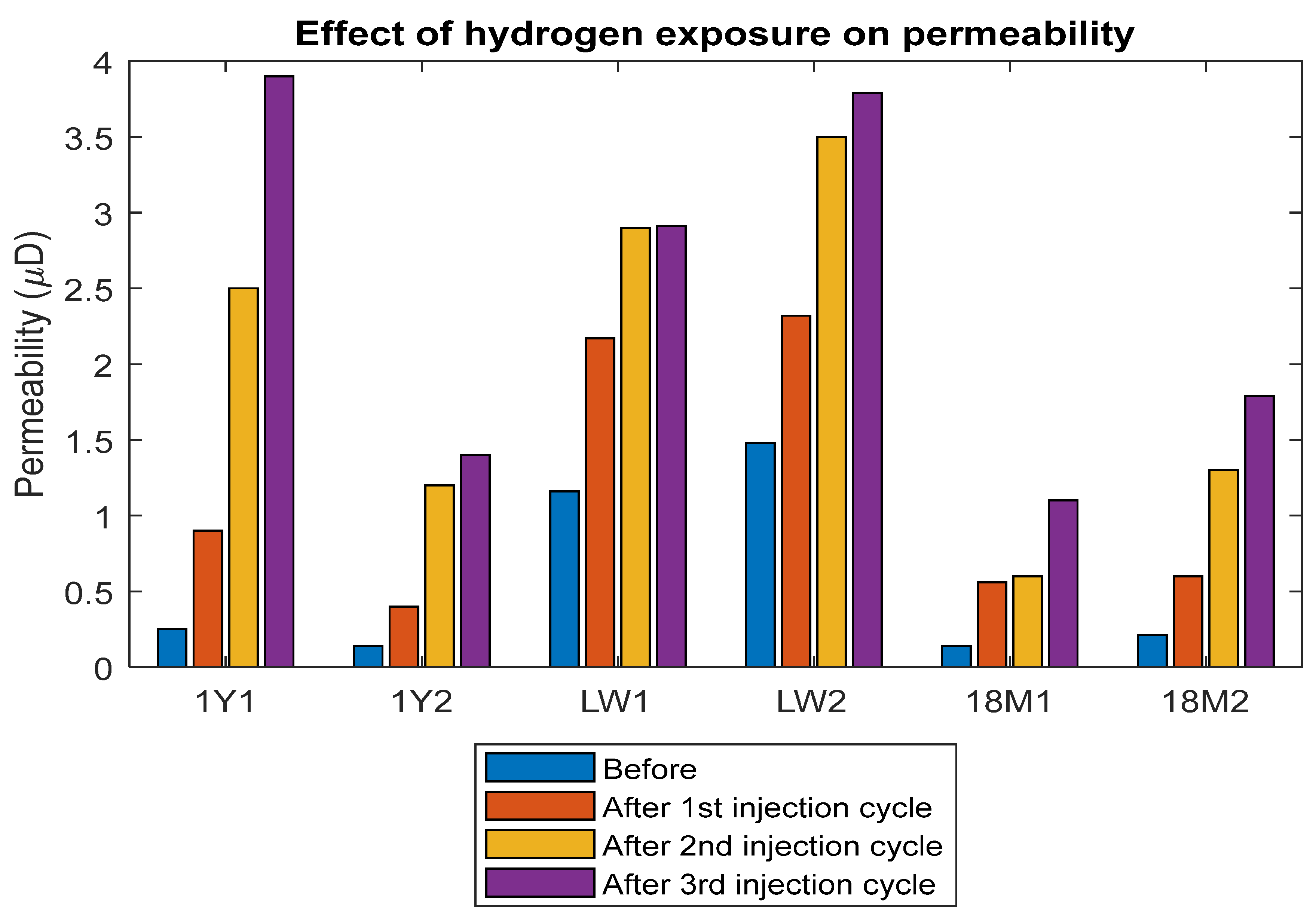
3.3. Permeability
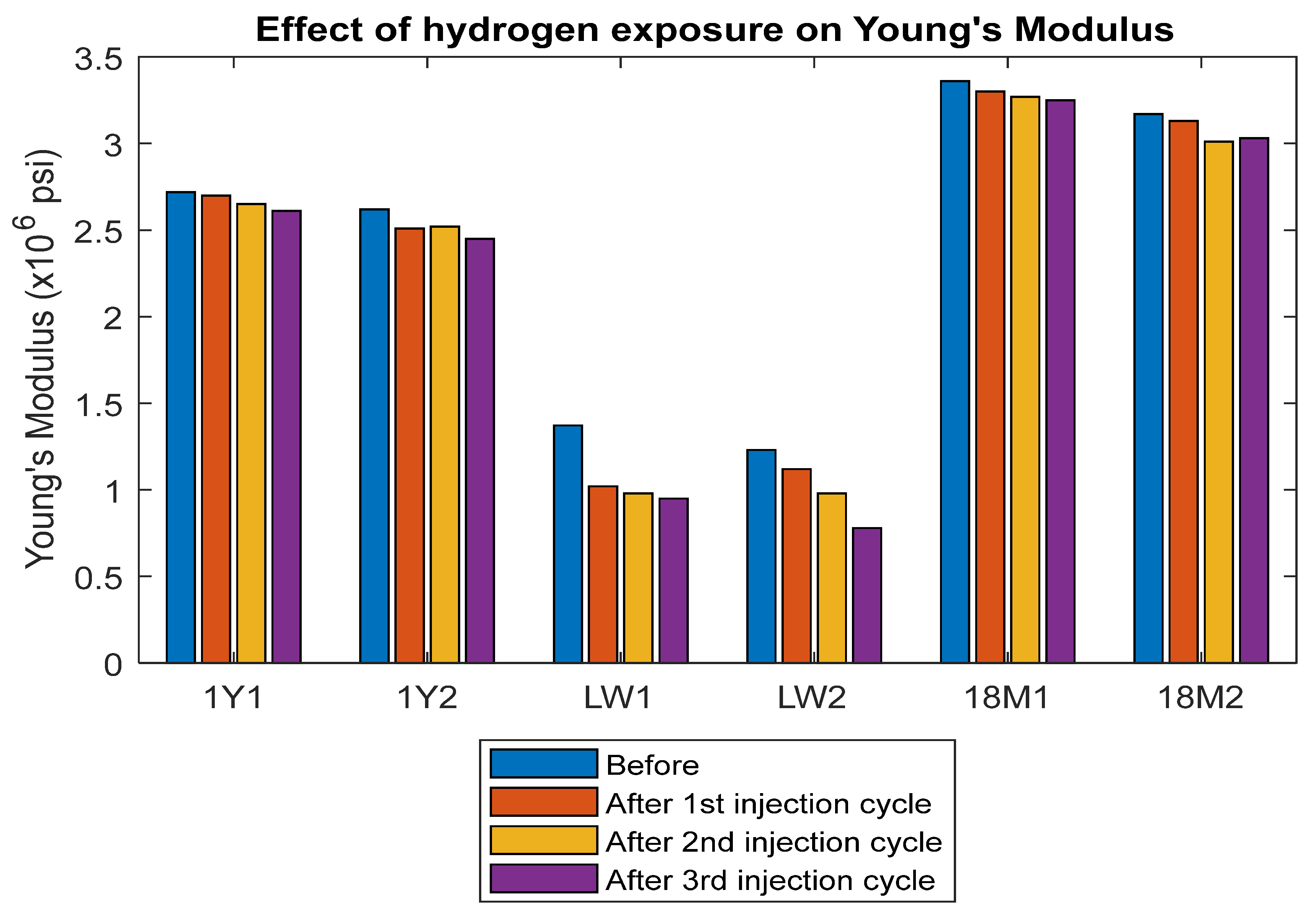
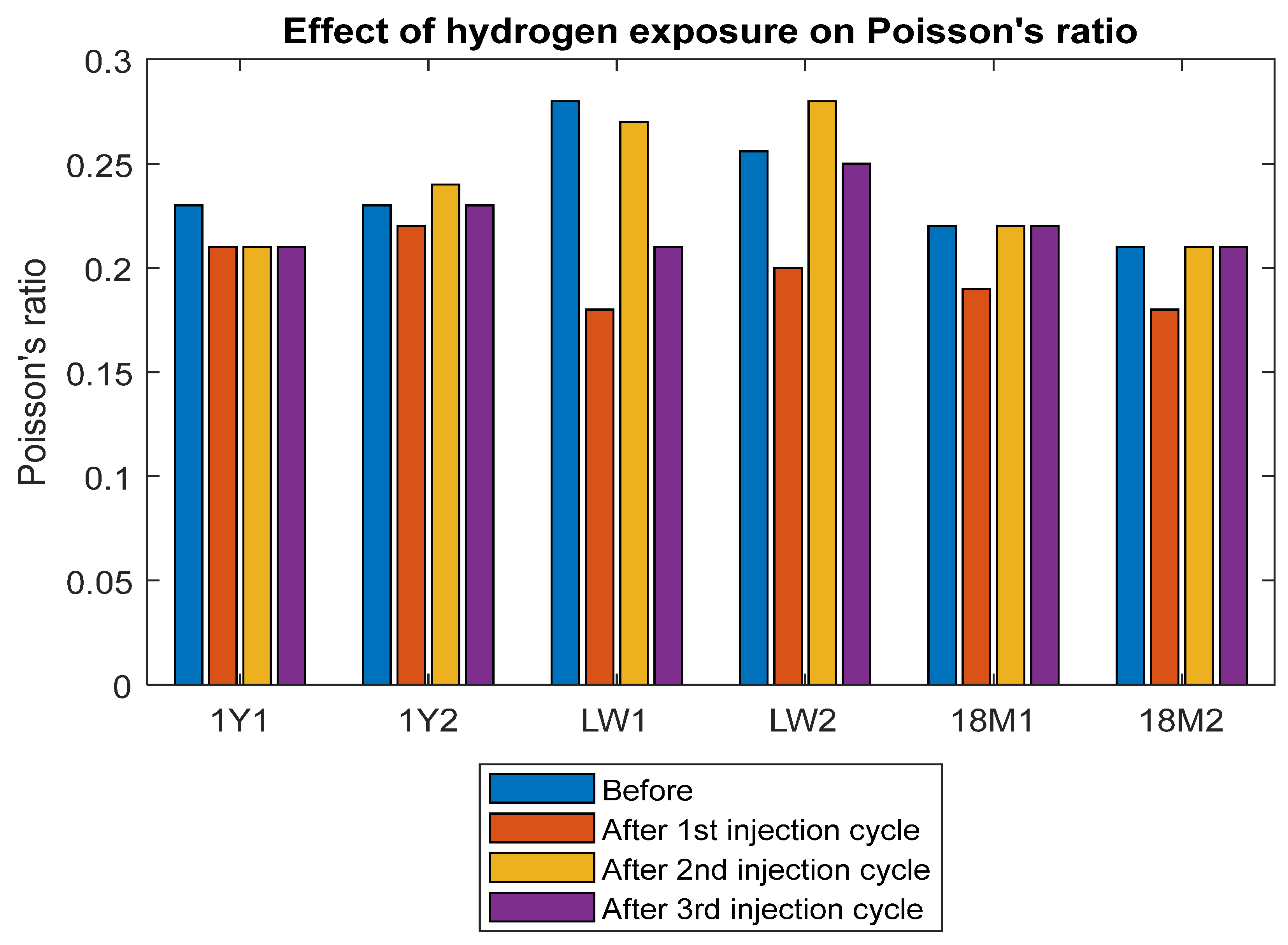
3.4. Modulus of Elasticity and Poisson’s Ratio
4. Conclusions
Author Contributions
Funding
Institutional Review Board Statement
Informed Consent Statement
Data Availability Statement
Acknowledgments
Conflicts of Interest
Appendix A

References
- Ifticene, M.A.; Yan, K.; Yuan, Q. Fueling a Carbon-Zero Future: Igniting Hydrogen Production from Petroleum Reservoirs via in-Situ Combustion Gasification. Energy Convers. Manag. 2023, 298, 117770. [Google Scholar] [CrossRef]
- Song, P.; Li, Y.; Yin, Z.; Ifticene, M.A.; Yuan, Q. Simulation of Hydrogen Generation via In-Situ Combustion Gasification of Heavy Oil. Int. J. Hydrogen Energy 2024, 49, 925–936. [Google Scholar] [CrossRef]
- Canbaz, C.H.; Aydin, H.; Canbaz, E.; Akberov, I.; Aksahan, F.; Hussain, A.; Emadi, H.; Temizel, C. A Comprehensive Review and Status of Renewable Resources and Oil & Gas Under the Supply and Demand Dynamics in the World. In Proceedings of the 82nd EAGE Conference and Exhibition, Amsterdam, The Netherlands, 18–21 October 2021. [Google Scholar] [CrossRef]
- Navaid, H.B.; Emadi, H.; Watson, M. A Comprehensive Literature Review on the Challenges Associated with Underground Hydrogen Storage. Int. J. Hydrogen Energy 2023, 48, 10603–10635. [Google Scholar] [CrossRef]
- Homoud, R.A.; Machado, M.V.B.; Daigle, H.; Sepehrnoori, K.; Ates, H. Enhancing Hydrogen Recovery from Saline Aquifers: Quantifying Wettability and Hysteresis Influence and Minimizing Losses with a Cushion Gas. Hydrogen 2024, 5, 327–351. [Google Scholar] [CrossRef]
- Thiyagarajan, S.R.; Emadi, H.; Hussain, A.; Patange, P.; Watson, M. A Comprehensive Review of the Mechanisms and Efficiency of Underground Hydrogen Storage. J. Energy Storage 2022, 51, 104490. [Google Scholar] [CrossRef]
- Fernandez, D.M.; Emadi, H.; Hussain, A.; Thiyagarajan, S.R. A Holistic Review on Wellbore Integrity Challenges Associated with Underground Hydrogen Storage. Int. J. Hydrogen Energy 2024, 57, 240–262. [Google Scholar] [CrossRef]
- Scherer, G.W.; Huet, B. Carbonation of Wellbore Cement by CO2 Diffusion from Caprock. Int. J. Greenh. Gas. Control 2009, 3, 731–735. [Google Scholar] [CrossRef]
- Hernández-Rodríguez, A.; Orlando, A.; Montegrossi, G.; Huet, B.; Virgili, G.; Vaselli, O. Experimental Analysis on the Carbonation Rate of Portland Cement at Room Temperature and CO2 Partial Pressure from 1 to 51 Bar. Cem. Concr. Compos. 2021, 124, 104271. [Google Scholar] [CrossRef]
- Strazisar, B.; Kutchko, B.; Huerta, N. Chemical Reactions of Wellbore Cement Under CO2 Storage Conditions: Effects of Cement Additives. Energy Procedia 2009, 1, 3603–3607. [Google Scholar] [CrossRef]
- Kutchko, B.G.; Strazisar, B.R.; Huerta, N.; Lowry, G.V.; Dzombak, D.A.; Thaulow, N. CO2 Reaction with Hydrated Class H Well Cement under Geologic Sequestration Conditions: Effects of Flyash Admixtures. Environ. Sci. Technol. 2009, 43, 3947–3952. [Google Scholar] [CrossRef]
- Kutchko, B.G.; Strazisar, B.R.; Dzombak, D.A.; Lowry, G.V.; Thaulow, N. Degradation of Well Cement by CO2 under Geologic Sequestration Conditions. Environ. Sci. Technol. 2007, 41, 4787–4792. [Google Scholar] [CrossRef] [PubMed]
- Carroll, S.; Carey, J.W.; Dzombak, D.; Huerta, N.J.; Li, L.; Richard, T.; Um, W.; Walsh, S.D.C.; Zhang, L. Review: Role of Chemistry, Mechanics, and Transport on Well Integrity in CO2 Storage Environments. Int. J. Greenh. Gas Control 2016, 49, 149–160. [Google Scholar] [CrossRef]
- Bai, M.; Zhang, Z.; Fu, X. A Review on Well Integrity Issues for CO2 Geological Storage and Enhanced Gas Recovery. Renew. Sustain. Energy Rev. 2016, 59, 920–926. [Google Scholar] [CrossRef]
- Gan, M.; Zhang, L.; Wang, Y.; Mei, K.; Fu, X.; Cheng, X.; Bai, M.; Liu, H.; Li, X. 3D Micro-Structural Changes of an Artificial Flow Channel in Wellbore Cement under Geologic CO2 Storage Conditions: Combined Effect of Effective Stress and Flow. Constr. Build. Mater. 2022, 325, 126761. [Google Scholar] [CrossRef]
- Gherardi, F.; Audigane, P.; Gaucher, E.C. Predicting Long-Term Geochemical Alteration of Wellbore Cement in a Generic Geological CO2 Confinement Site: Tackling a Difficult Reactive Transport Modeling Challenge. J. Hydrol. 2012, 420, 340–359. [Google Scholar] [CrossRef]
- Manceau, J.C.; Tremosa, J.; Lerouge, C.; Gherardi, F.; Nussbaum, C.; Wasch, L.J.; Alberic, P.; Audigane, P.; Claret, F. Well Integrity Assessment by a 1:1 Scale Wellbore Experiment: Exposition to Dissolved CO2 and Overcoring. Int. J. Greenh. Gas Control 2016, 54, 258–271. [Google Scholar] [CrossRef]
- Fatah, A.; Ramadan, M.A.; Al-Yaseri, A. Hydrogen Impact on Cement Integrity during Underground Hydrogen Storage: A Minireview and Future Outlook. Energy Fuels 2024, 38, 1713–1728. [Google Scholar] [CrossRef]
- Reitenbach, V.; Ganzer, L.; Albrecht, D.; Hagemann, B. Influence of Added Hydrogen on Underground Gas Storage: A Review of Key Issues. Environ. Earth Sci. 2015, 73, 6927–6937. [Google Scholar] [CrossRef]
- Jacquemet, N.; Chiquet, P.; Grauls, A. Hydrogen Reactivity with (1) a Well Cement—PHREEQC Geochemical Thermodynamics Calculations. In Proceedings of the 1st Geoscience & Engineering in Energy Transition Conference, Strasbourg, France, 16–18 November 2020; Volume 2020, pp. 1–5. [Google Scholar] [CrossRef]
- Ugarte, E.R.; Salehi, S. A Review on Well Integrity Issues for Underground Hydrogen Storage. J. Energy Resour. Technol. 2022, 144, 042001. [Google Scholar] [CrossRef]
- Fernandez, D.M.; Emadi, H.; Thiyagarajan, S.; Hussain, A.; Ispas, I. Effects of Hydrogen on Class H Well Cement’s Properties Under Geological Storage Conditions. In Proceedings of the 57th U.S. Rock Mechanics/Geomechanics Symposium, Atlanta, GA, USA, 25–28 June 2023; ARMA-2023-0735. [Google Scholar] [CrossRef]
- Hussain, A.; Al-Hadrami, H.; Emadi, H.; Altawati, F.; Thiyagarajan, S.R.; Watson, M. Experimental Investigation of Wellbore Integrity of Depleted Oil and Gas Reservoirs for Underground Hydrogen Storage. In Proceedings of the Offshore Technology Conference, Houston, TX, USA, 2–5 May 2022. [Google Scholar] [CrossRef]
- Al-Hadrami, H.; Emadi, H.; Hussain, A. Investigating the Effects of Hydrogen on Wet Cement for Underground Hydrogen Storage Applications in Oil and Gas Wells. Int. J. Struct. Constr. Eng. 2022, 16, 252–258. [Google Scholar]
- Cracolici, F.; Iorio, V.S.; Parrozza, F.; Sabatino, L.M.F.; Massara, E.P.; Consonni, A.; Viareggio, A.; Altimare, C.W.; Gori, S.; Colombo, L.; et al. Experimental Investigation of Cement Compatibility in Underground Hydrogen Storage in Depleted Reservoir. In Proceedings of the International Petroleum Technology Conference, Bangkok, Thailand, 1–3 March 2023. [Google Scholar] [CrossRef]
- Al-Yaseri, A.; Fatah, A.; Zeng, L.; Al-Ramadhan, A.; Sarmadivaleh, M.; Xie, Q. On Hydrogen-Cement Reaction: Investigation on Well Integrity during Underground Hydrogen Storage. Int. J. Hydrogen Energy 2023, 48, 35610–35623. [Google Scholar] [CrossRef]
- Iorio, V.S.; Cracolici, F.; Parrozza, F.; Sabatino, L.M.; Massara, E.P.; Consonni, A.; Tritto, C.; De Simoni, M. Cement to Safeguard the Wells Integrity in Underground Hydrogen Storage: An Experimental Investigation. Chem. Eng. Trans. 2022, 96, 307–312. [Google Scholar] [CrossRef]
- Aftab, A.; Hassanpouryouzband, A.; Martin, A.; Kendrick, J.E.; Thaysen, E.M.; Heinemann, N.; Utley, J.; Wilkinson, M.; Haszeldine, R.S.; Edlmann, K. Geochemical Integrity of Wellbore Cements during Geological Hydrogen Storage. Environ. Sci. Technol. Lett. 2023, 10, 551–556. [Google Scholar] [CrossRef]
- Hussain, A.; Emadi, H.; Thiyagarajan, S.R.; Ispas, I.; Watson, M.; Leggett, S.E. Assessing the Viability of Oilwell Cement for Underground Hydrogen Storage. In Proceedings of the 57th U.S. Rock Mechanics/Geomechanics Symposium, Atlanta, GA, USA, 25–28 June 2023. ARMA-2023-0746. [Google Scholar] [CrossRef]
- Nasiri, A.; Ravi, K.; Prohaska-Marchried, M.; Feichter, M.; Raith, J.; Coti, C.; Baronio, E.; Busollo, C.; Mantegazzi, A.; Pozzovivo, V.; et al. An Interdisciplinary Approach to Investigate the Cement Integrity for Underground Hydrogen Storage Wells. In Proceedings of the SPE EuropEC—Europe Energy Conference featured at the 84th EAGE Annual Conference & Exhibition, Vienna, Austria, 5–8 June 2023. [Google Scholar] [CrossRef]
- Ugarte, E.R.; Tetteh, D.; Salehi, S. Experimental Studies of Well Integrity in Cementing during Underground Hydrogen Storage. Int. J. Hydrogen Energy 2024, 51, 473–488. [Google Scholar] [CrossRef]
- Lesti, M.; Tiemeyer, C.; Plank, J. CO2 Stability of Portland Cement Based Well Cementing Systems for Use on Carbon Capture & Storage (CCS) Wells. Cement Concrete Res. 2013, 45, 45–54. [Google Scholar] [CrossRef]
- Wang, W.; Yue, Q. The Time Variation Law of Concrete Compressive Strength: A Review. Appl. Sci. 2023, 13, 4947. [Google Scholar] [CrossRef]
- Al-Khaiat, H.; Fattuhi, N. Long-Term Strength Development of Concrete in Arid Conditions. Cem. Concr. Compos. 2001, 23, 363–373. [Google Scholar] [CrossRef]
- Rincon, F.; Abid, K.; Arbad, N.; Teodoriu, C. A Comprehensive Analysis of Class H Cement Unconfined Compressive Strength Using Cubical and Cylindrical Samples. J. Pet. Sci. Eng. 2022, 215, 110692. [Google Scholar] [CrossRef]
- Al-Yaseri, A.; Wolff-Boenisch, D.; Fauziah, C.A.; Iglauer, S. Hydrogen Wettability of Clays: Implications for Underground Hydrogen Storage. Int. J. Hydrogen Energy 2021, 46, 34356–34361. [Google Scholar] [CrossRef]
- Yekta, A.E.; Pichavant, M.; Audigane, P. Evaluation of Geochemical Reactivity of Hydrogen in Sandstone: Application to Geological Storage. Appl. Geochem. 2018, 95, 182–194. [Google Scholar] [CrossRef]
- Altawati, F.; Emadi, H. Effects of Cyclic Cryogenic Treatment on Rock Physical and Mechanical Properties of Eagle Ford Shale Samples—An Experimental Study. J. Nat. Gas Sci. Eng. 2021, 88, 103772. [Google Scholar] [CrossRef]
- API-RP-40; Recommended Practices for Core Analysis. American Petroleum Institute: Washington, DC, USA, 1998.
- Zoback, M.D. Reservoir Geomechanics; Cambridge University Press: Cambridge, UK, 2010; ISBN 9780521146197. [Google Scholar]
- Teodoriu, C.; Asamba, P.; Ichim, A. Well Integrity Estimation of Salt Cements with Application to Long Term Underground Storage Systems. In Proceedings of the SPE Europec featured at 78th EAGE Conference and Exhibition, Vienna, Austria, 30 May–2 June 2016. [Google Scholar] [CrossRef]
- Ahmed, A.; Mahmoud, A.A.; Elkatatny, S. The Effect of Polypropylene Fiber on the Curing Time of Class G Oil Well Cement and Its Mechanical, Petrophysical, and Elastic Properties. J. Pet. Explor. Prod. Technol. 2023, 13, 1181–1196. [Google Scholar] [CrossRef]
- Machado, M.V.B.; Delshad, M.; Sepehrnoori, K. Modeling Self-Sealing Mechanisms in Fractured Carbonates Induced by CO2 Injection in Saline Aquifers. ACS Omega 2023, 8, 48925–48937. [Google Scholar] [CrossRef] [PubMed]
- Brunet, J.-P.L.; Li, L.; Karpyn, Z.T.; Huerta, N.J. Fracture Opening or Self-Sealing: Critical Residence Time as a Unifying Parameter for Cement–CO2–Brine Interactions. Int. J. Greenh. Gas. Control 2016, 47, 25–37. [Google Scholar] [CrossRef]


| Clinker | Percentage |
|---|---|
| C3S | 47.13 |
| C2S | 28.27 |
| C4AF | 17 |
| C3A | 0.65 |
| CaSO4 | 4.72 |
| Na2O | 0.09 |
| MgO | 1.09 |
| K2O | 0.45 |
| TiO2 | 0.18 |
| MnO | 0.07 |
| ZnO | 0.01 |
| SrO | 0.07 |
| Free Lime | 0.26 |
| Batch | Before Exposure | After 1st Cycle | After 2nd Cycle | After 3rd Cycle |
| 1Y1 | 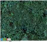 | 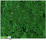 |  | 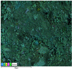 |
| 1Y2 | 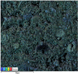 | 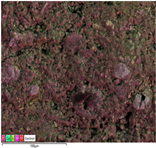 | 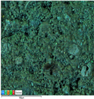 | 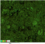 |
| LW1 | 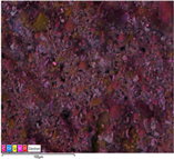 | 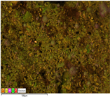 | 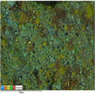 | 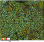 |
| LW2 | 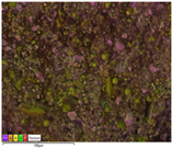 | 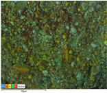 |  | 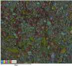 |
| 18M1 |  | 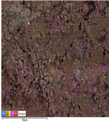 | 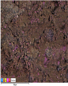 | 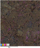 |
| 18M2 | 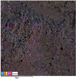 | 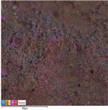 |  |  |
Disclaimer/Publisher’s Note: The statements, opinions and data contained in all publications are solely those of the individual author(s) and contributor(s) and not of MDPI and/or the editor(s). MDPI and/or the editor(s) disclaim responsibility for any injury to people or property resulting from any ideas, methods, instructions or products referred to in the content. |
© 2024 by the authors. Licensee MDPI, Basel, Switzerland. This article is an open access article distributed under the terms and conditions of the Creative Commons Attribution (CC BY) license (https://creativecommons.org/licenses/by/4.0/).
Share and Cite
Hussain, A.; Emadi, H.; Thiyagarajan, S.R.; Fernandez, D.M.; Ispas, I.; Watson, M. Non-Destructive Cyclic Analysis of Sealing Ability of Well Cement for Seasonal Underground Hydrogen Storage. Appl. Sci. 2024, 14, 7973. https://doi.org/10.3390/app14177973
Hussain A, Emadi H, Thiyagarajan SR, Fernandez DM, Ispas I, Watson M. Non-Destructive Cyclic Analysis of Sealing Ability of Well Cement for Seasonal Underground Hydrogen Storage. Applied Sciences. 2024; 14(17):7973. https://doi.org/10.3390/app14177973
Chicago/Turabian StyleHussain, Athar, Hossein Emadi, Sugan Raj Thiyagarajan, Diana Maury Fernandez, Ion Ispas, and Marshall Watson. 2024. "Non-Destructive Cyclic Analysis of Sealing Ability of Well Cement for Seasonal Underground Hydrogen Storage" Applied Sciences 14, no. 17: 7973. https://doi.org/10.3390/app14177973
APA StyleHussain, A., Emadi, H., Thiyagarajan, S. R., Fernandez, D. M., Ispas, I., & Watson, M. (2024). Non-Destructive Cyclic Analysis of Sealing Ability of Well Cement for Seasonal Underground Hydrogen Storage. Applied Sciences, 14(17), 7973. https://doi.org/10.3390/app14177973