Article

Control System Hardware Design, Analysis and Characterization of Electromagnetic Diaphragm Pump

by
Szymon Skupień
1,†,
Paweł Kowol
1,†,
Giacomo Capizzi
2,3,† and
Grazia Lo Sciuto
1,3,*,†
1
Department of Mechatronics, Silesian University of Technology, Akademicka 10A, 44-100 Gliwice, Poland
2
Department of Mathematics Applications and Methods for Artificial Intelligence, Silesian University of Technology, Kaszubska 23, 44-100 Gliwice, Poland
3
Department of Electrical, Electronics and Informatics Engineering, University of Catania, Viale Andrea Doria 6, 95125 Catania, Italy
*
Author to whom correspondence should be addressed.
All authors contributed equally to this work.
Appl. Sci. 2024, 14(17), 8043; https://doi.org/10.3390/app14178043 (registering DOI)
Submission received: 16 July 2024 / Revised: 19 August 2024 / Accepted: 1 September 2024 / Published: 8 September 2024

Abstract

:
In this article, a novel electromagnetic diaphragm pump design controlled by an Arduino NANO microcontroller is proposed to pump liquid inside the pumping chamber completely separated from mechanical and transmission parts. The prototype is primarily based on alternating the polarity of two electromagnets that attract or repel a permanent magnet located on a flexible diaphragm. The system hardware layout is completed by electronic components:. an Arduino NANO microcontroller created by Atmel, Headquarters San Jose, California. and display within the cabinet to control the polarization of the electromagnets and exhibit the temperature inside the pump. The electromagnetic pump and control system consist of innovative approaches as a solution for the treatment of unclean water and integration with solar panel systems. In addition, the measurement tests of the electromagnetic pump, including the temperatures of electromagnets and the quantity of the pumped liquid within the chamber, indicate a dependence on the selected speed of the electromagnet’s polarization. The electromagnetic pump achieves high efficiency as a combination of the temperature and the amount of liquid that can be regulated and controlled by the switching speed of the electromagnet’s polarization.

1. Introduction

For the industrial transportation of liquid and metal, diaphragm pumps are widely used in the chemical engineering and pharmaceutical industries [1,2]. The realization of pump systems plays an essential role in manipulating and driving volumes of solution [3]. The diaphragm pumps, considered to be positive displacement pumps, control the flow rate of the liquid with various levels of viscosity and are used to avoid the problem of the contamination of liquid or corrosive chemicals that affect several processes [4]. One type of diaphragm pump considered is the electromagnetic diaphragm pump (EMP), which has a pump body, a spring, a diaphragm, and an electromagnet with variable pole areas and single-direction valves [5,6]. The electromagnet with variable pole areas is composed of an electromagnetic coil, an iron core, a magnetic isolation ring, and an inner and outer armature [7]. In the EMP, the fluid flow, the magnetic field and the electric field parameters are studied as functions of the geometry of magnets and channel heights to achieve the maximum flow rate and efficiency of the pump [8,9,10]. An integral DC electromagnet with a conical armature was simulated using Ansoft Maxwell software (ANSYS, Inc. Headquarters, Southpointe, 2600 Ansys Drive, Canonsburg, PA 15317 USA) and compared to the displacement–force characteristics of the high-speed electromagnets in [11]. The electromagnet with variable pole areas is determined by analyzing the equivalent magnetic circuit, and experiments were conducted to verify the results of theoretical calculations [12,13]. The electrode material in Mo and NdFeB, the permanent magnet, to develop a pump was designed to transport liquid metal in [14,15,16]. The electromagnetic pump for microfluidic applications presents the fluid driven periodically through the channel with the coil input current that generates an electromagnetic force and a diaphragm deflection in [17]. The characteristics of an EMP with a rotating magnet under low inlet pressure is studied in [18,19]. Furthermore, in recent studies, the problem of design based on 3D printing technology, and the numerical analysis of electromagnetic pumps through simulation and experiments using a single chamber and three chambers, for enhancing their performance, have attracted the attention in the literature [20,21,22].
In this article, we proposed the design of an electromagnetic diaphragm pump prototype in which the mechanism is performed by the means of a magnetic field that attracts or repels a permanent magnet placed within a flexible film. The two electromagnets change the position of the permanent magnet located on the membrane of the pump. The electromagnetic forces allow us to change the position of the permanent magnet, giving the pressure to pump the water [23]. The electromagnet generates a magnetic field by passing an electric current through a coil wound around a core made of ferromagnetic material. Therefore, the pump can suck water, as well as dirty water, and it can be possible to clean and filter it using membranes. For this reason, the device could be used in solar panels to pump water and warm it. Therefore, a control system of the electromagnetic diaphragm pump based on the Arduino NANO ATmega328 controller includes a display, two drivers to change the polarization of the magnets, and safety devices. The mechanical and electric elements and the peripheral devices, such as fans for cooling the electromagnetic system, are controlled by the software program. Therefore, to control the direction of the polarity change, the H-bridge is included. The performance of the device and the check valves, as well as the design and selection of materials for the pump body, including the material used to make the pump diaphragm, were analyzed.
The main contributions of this work include the following:
  • The design of an electromagnetic pump diaphragm, including the control system based on the Arduino platform;
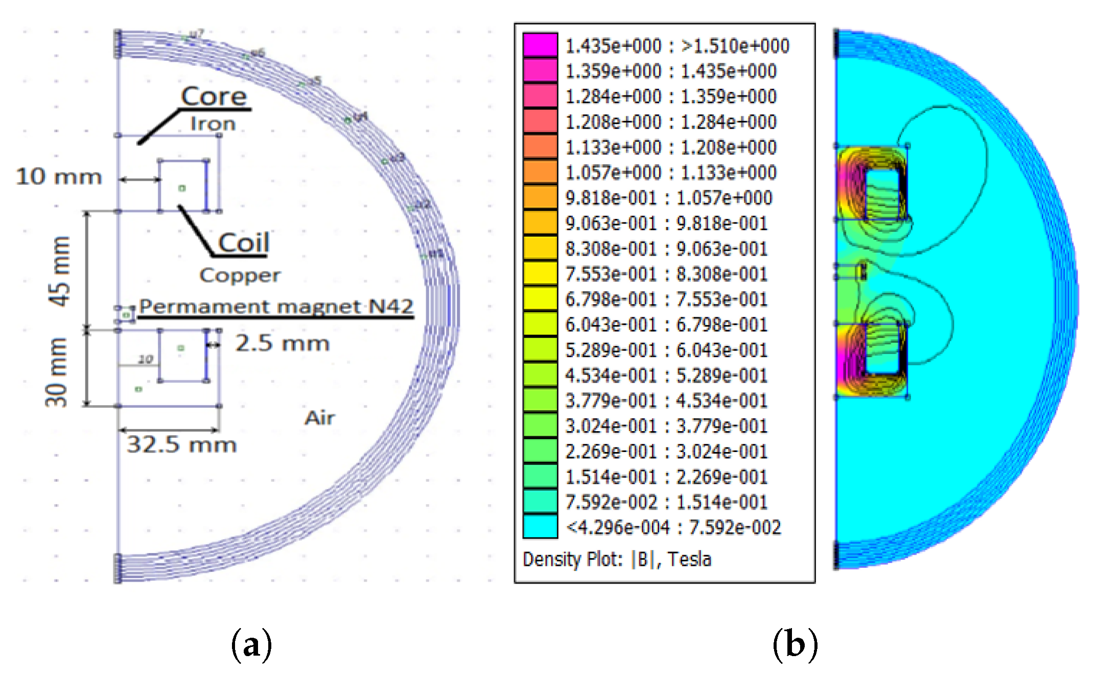
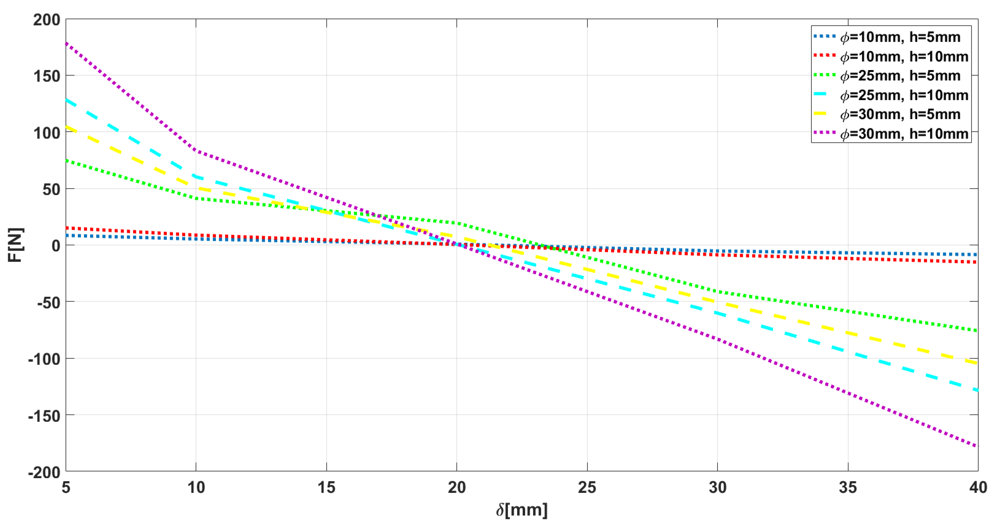
  • The simulations and calculations performed using the FEMM program for the analysis and distribution of the magnetic field and the force generated inside the pump;
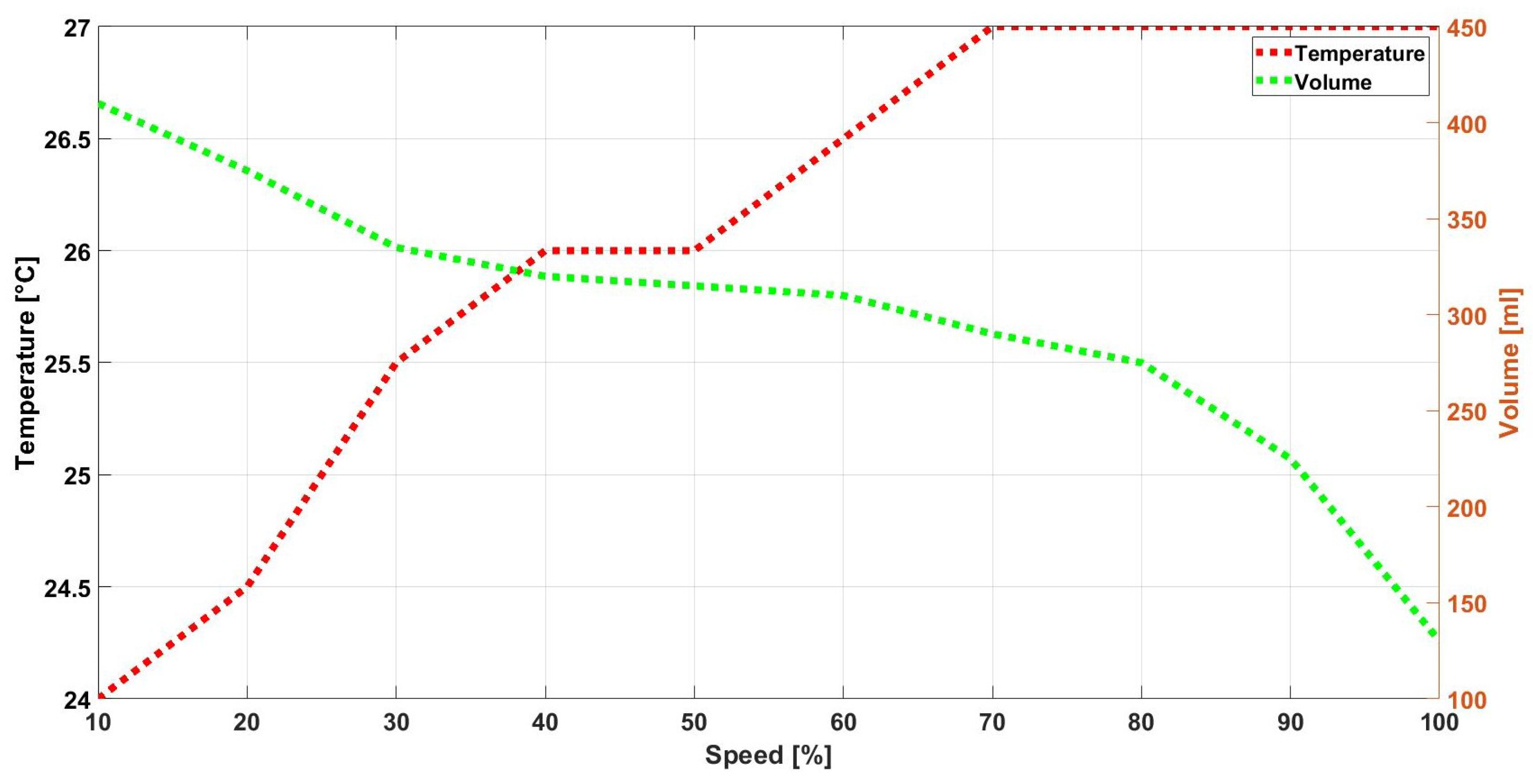
  • The measurements of the temperature of the electromagnetic pump, the liquid volume, and pump speed were conducted.
The novelty of this work is in the electromagnetic diaphragm pump design controlled by an Arduino NANO microcontroller for the treatment of unclean water and for integration with solar panel systems. The main benefit of this design is that the liquid within the pumping chamber is completely separated from the mechanical and transmission parts and is controlled using the Arduino microcontroller, as well as the volume and temperature of the electromagnets. In addition, the conducted measurements have proved the linearity of the pump liquid controlled by the switching speed of the electromagnet’s polarization.
The rest of this paper is organized as follows: the design and description of the electromagnetic diaphragm pump is presented in Section 2. An analysis of the simulation model of the electromagnet is provided in Section 3. In Section 4, the experimental results of the electromagnetic diaphragm pump are reported. Finally, Section 5 concludes this work.

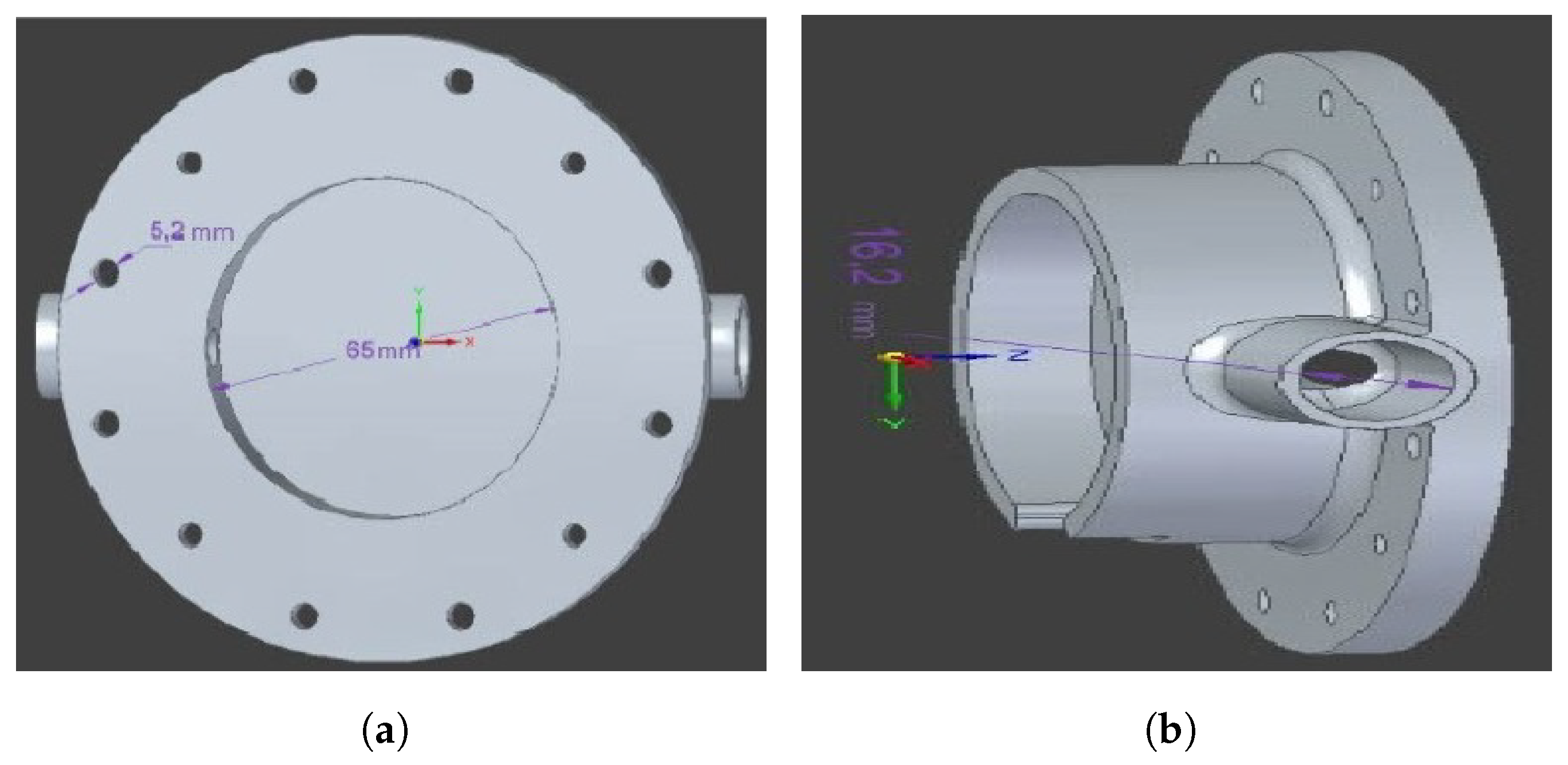
2. Design and Structure of Electromagnetic Pump

2.1. Electromagnetic Pump Description

In the electromagnetic diaphragm pump system prototype, the design of the electrical system of the electromagnet coil and the selection and construction of the pump control system with the field calculations, and and the conducting of tests for the magnetic pump system, were carried out at the laboratory of Department of Mechatronics, Silesian University of Technology, Gliwice. The prototype pumps small amounts of liquid and starts the so-called dry, i.e., exhaust fluid without first flooding the pump chamber. According to the design, the pump can generate a force that allows for the suction out of the liquid at the different height levels where the device is located. This height was estimated to be 0.5 m below the level of the location of the pump. Additionally, the structural elements of the housing was realized using 3D printing technology, including the development of software enabling the supervision of the device and its operation. The pump device creates a pressure difference between the inlet (suction side) and the outlet of the pump, allowing for the transport of liquid or sediment. The pump transfers the mechanical energy to a fluid (liquid or gas) by raising its pressure through a rotor, piston or membrane to compress it. The operation of a diaphragm pump involves two flexible membranes mounted on a shared shaft that repeatedly moves up and down to pump fluids. This movement creates a vacuum, which allows fluid to enter through the inlet of the pump. The membranes are in motion mechanically using the pistons (Figure 1a).
The designed pump realized in the laboratory is constituted of a membrane, a permanent magnet, two electromagnets, two valves and the chamber. The cylinder pump chamber has dimensions of 65 × 15 mm. The cylinder permanent magnet, N42, has dimensions of 25 × 10 mm. The electromagnet 65 × 30 core dimension is 30 × 10 mm. The coil is wounded with a 0.3 mm length of wire and 2300 turns. The circular membrane has a diameter of 65 mm and a thickness of 1.5 mm. The mechanical force generated by the electromagnet is transferred through the magnetic field interacting with the permanent magnet located in the membrane structure (Figure 1b). The operation of the pump is based on changing of the polarity of the electromagnets. The interaction between a permanent magnet and the electromagnets causes the moving of the diaphragm. When the device is supplied (24 V), the current generated by the magnetic forces in the designed pump flows through the electromagnets. One of the electromagnets is positively polarized according to the direction of current flow, and the other one is negatively polarized. Then, the magnetic field generated by the electromagnets interacts with a permanent magnet embedded in the middle of the diaphragm. As a result, the diaphragm will move toward the direction of the electromagnets. The motion of the diaphragm creates a vacuum in the pump chamber. In Figure 1a, the operating cycle of the pump is distinguished:
  • Opening of the suction valve;
  • Medium suction;
  • Medium compression of air;
  • Opening of the discharge valve;
  • Compressed medium outlet.
The inlet valve opens and liquid fills the pump chamber. The changing of the polarity in the electromagnets rapidly reverses the cycle. The outlet valve opens and the inlet valve closes so the water is forced out from the chamber. The main benefit of this design is that the liquid within the pumping chamber is completely separated from the mechanical and transmission parts. The pump can be used to handle dangerous and hazardous chemicals, as the risk of leakage into the system is minimized in mechanical or electrical devices in the event of a break in the continuity of the membrane.

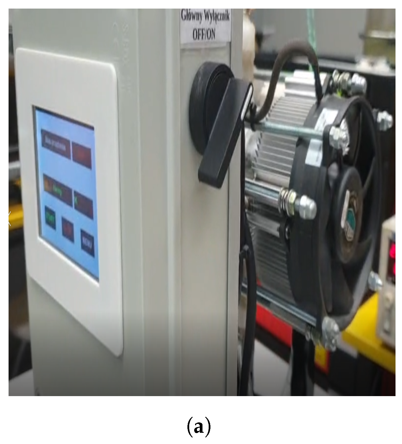
2.2. Technology and Hardware in the Electromagnetic Diaphragm Pump

The electromagnetic diaphragm pump is designed to deliver certain amounts of liquid to a cylindrical chamber that has an inlet and an outlet valve to control the flow of liquid. In the realized pumping chamber, the electromagnets are located on a membrane composed of embedded steel frame structures that attract or repel the permanent magnet (Figure 1b). The permanent magnets are used for maintaining the magnetic field and for the high coercivity that gives it the ability to maintain the magnetism in the presence of an opposite magnetic field. To ensure the proper operation of the proposed realized pump, solenoid electromagnets with a round shape and a threaded hole were powered at 24 V DC, widely used in most existing industrial systems and control cabinets. They were switched on and off with an electrical voltage. They generated a magnetic field induced by voltage without additional elements such as spring shafts or central heating pistons to eliminate any interference from external elements that could remain mechanically connected to the pump diaphragm. As in case of the conventional pumps, the mechanical energy is transmitted through numerous varieties of rollers or cables. The appropriate configuration of electromagnets and the dimensions of the chambers were established using a simulation model. The dimension of the electromagnet is 65 × 30 mm, determined on the basis of the size of the pumping chamber and its limited weight. Obviously, the bigger electromagnet generates more force, increasing exponentially, as well as the mass of the core and its winding wire.
The pump body was realized with a selection of materials. The ease and speed of 3D printing technology was used to realize the pump body using PET-G material, due to its relativelyhigh mechanical properties and water resistance (Figure 2a,b). The system does not mix with the water on one side of the membrane, while on the other side, the liquid is sucked in and ejected from the wet part. Additionally, in order to enhance the operation and efficiency of the pump, “light” check valves and spring check valves had been designed due to the low pressure in the switching of positions.

2.3. Control System and Microcontroller and Design of the Control System as a PCB

The electromagnetic diaphragm pump has been assembled with the panel display and multi-functional electronics contained in the control cabinet. The panel display controls and measures the variations of some parameters, such as temperature and the speed of the electromagnet within the diaphragm pump. The control cabinet incorporates the following electronic components, as shown in Figure 3a:
  • Arduino NANO (Controller Nano V3.0 ATmega328P created by Atmel, Headquarters San Jose, CA, USA);
  • PCB boards (EZ-Stream, China);
  • Nextion touch display (3rd Flr, Bld A, International Import Expo Hall, No. 663, Bulong Rd, Longgang Dist, Shenzhen, China);
  • START STOP button and emergency disconnect switch (Benkpak International China);
  • BUCK LM2596S voltage converter set to 5 V and BUCK XL4015 type voltage converter set to 12 V (Product origin: China);
  • Housings with fuses and Relay (Product origin: China);
The supply voltage was specified as 24 V DC, used as the nominal value of the devices. However, to supply the cooling system and to reduce the voltage at 12 V, the voltage converter was used. The 12 V circuit was only used in the device electromagnet fan circuit. The remaining elements operated at 24 V. Another converter is necessary to reduce the voltage source at 5 V for the control system, the display, switching, relay, the fans and the temperature sensors. The control system includes a microcontroller, sensors and the peripheral devices necessary for its operation. The Arduino NANO microcontroller, based on the ATmega 328 processor, was selected for its small dimension and easier assembly, and for the hardware capabilities. Two electromagnets are required for the simultaneous repulsion and attraction of the permanent magnet during the power supply and for cyclical polarization in order to provide a sufficient fluid pumping force. To control the direction of rotation of the DC motors, the “H” bridge arrangement was used. The BTS7960 half-bridge system with high current and voltage efficiency was selected with a voltage of 5 V, which was required for the bridge to operate and to increase the limit value of the current (2 A). In order to obtain an adequate supply of the maximum current to allow for the safe operation and control of the electromagnet, we proposed the use of connection bridge channels. The controller is based on BTS7960 elements, and the second engine controller is a controller built on two BTS7960 H-type half-bridge systems. The controller can control a device with a maximum current of 43 A. The operating voltage of the actuating device ranges from 6 to 27 V. The module allows us to change the direction of motor rotation. The module uses a 74HC244 system that isolates the control system from the power circuits. The BTS7960 systems have thermal, short-circuit and overload protections. The module control is powered by 5 V DC. The great advantage of the system is the heat sink and the power reserve that should significantly reduce the heat generation. Additionally, in order to increase the ability to remove the heat from the device’s control cabinet, a 24 V fan was used during system tests to cool the heat sinks of the control electronics of the bridge elements and the H-bridge half-bridges. A controller based on BTS7960 half-bridge components has more protections against opposite polarity and decreases its temperature after cooling by fan and during the continuous operation of the device at the highest speed for 10 min. As the temperature of the electromagnets increases, the force generated by it decreases the strength of electromagnet. The DS18B20 sensor was used for the measurement of temperature. At the design stage, an LCD display and buttons were created (Figure 3a). A Nextion brand touch panel was selected to control the cabinet, and the LCD display had been programmed to read the individual parameters. Communication with the panel takes place via UART (Figure 3b).
The display software is based on simple commands and functions structurally similar to the C language for the ARDUINO microcontroller. The system device needs to safely dissipate heat from electromagnets using a radiator with a fan as a cooling system and to protect against short-circuit currents using two fuses. The 6.3 A and 1 A fuses were used, respectively, to protect the power circuits and auxiliary devices, such as converter voltage.

3. Model and Simulation

Model and simulation of the electromagnetic pump were performed using the Finite Element Method Magnetics (FEMM) software package (version FEMM 4.2 Magnetics, creator David Meeker from Waltham, MA 02451-1196), used for solving electromagnetic problems.In particular, the simulation had been performed to establish the size of the chamber and the distance of the electromagnet in the electromagnetic pump in order to maximise the magnetic force. In the conducted simulation, the cross-section model of electromagnetic pump’s chamber presents the permanent magnet located in the middle of two steel frame structures of electromagnets that attract and repel the permanent magnet, as in Figure 4a. The boundary conditions are listed within a group of ready-made functions located under the FEEM solver and related to the Dirichlet boundary conditions. The grid is also optimized by a function built into the FEMM program. The model structure presents as geometrical parameters the length ( ϕ ) and height (h) of the permanent magnet, and the distance ( δ ) of the permanent magnet and electromagnet frames change the force in the electromagnet. In the calculation model, Figure 4b, the distance δ between the electromagnet frames and permanent magnet varies in the range of 5 mm to 40 mm, as reported in Figure 5.
Therefore, the force from the Maxwell stress tensor, the force of attraction of the frame by the electromagnet and, consequently, the pump’s suction force, were calculated. Simulations were carried out and the core material was determined in accordance with the catalog note steel in FEEM, and the parameters of the coil were set at 2300 turns of copper wire with a cross-section of 0.3 mm and current of 2 A. The core is made of iron with the dimensions shown in Figure 5a. The permanent magnet will be attracted and repelled by the electromagnet frames over a shorter distance (5 mm) that that obtained by the simulation. The magnetic force is greater than 150 N when the permanent magnet is located at the end position or attached or closer to the first or second electromagnet. The voltage varies continuously and applied to the first and second electromagnet in the pumping chamber. The minimum and maximum force are useful to establish the size of the chamber. In Figure 5, the simulation results exhibit the relation of the magnetic force and the geometrical parameter as the dimension of chamber and the distance δ between the electromagnet frames and the permanent magnet in the electromagnetic diaphragm pump. The maximum magnetic force is obtained for the dimension δ of 5 mm.
Analyzing the results, an insufficient force is associated with the increase on the diaphragm stroke. The increment of the force during the suction and compression of liquids is essential. So, the metal frame was replaced with a permanent magnet. The distance value δ is set as a function of the dimension of the compression and pressing chambers. The N42 neodymium magnet was used as a permanent magnet. Then, simulations were performed to select the size and shape of pellet in order to maximize the magnetic force. Starting from the simulation model, the permanent magnet with dimensions of 25 × 10 mm was selected depending on the size pellets, the elasticity of the membrane and the strength force and stroke. The use of permanent magnets and the electromagnets can provide changes in the force and stroke membranes with proper control, which significantly increases the compression force generated by the pump.

Device Operation Concept

The electromagnetic diaphragm pump is composed of a pump chamber, a diaphragm and an electromagnetic coil, as depicted in Figure 6a,b. The dimension of the pump chamber is 65 × 45 mm, and the distance between the electromagnets is 5 mm to avoid the permanent magnet sticking to the core. The rubber membrane has a length of 64 mm and a thickness of 1.5 mm, and it is made of Butyl rubber (IIR) due to the specificity of the environment, the chemical activity, contact with the pumped liquid and its flexibility at low temperatures. The IIR is a synthetic rubber produced by copolymerizing isobutylene with small amounts of isoprene, valued for its resistance to high temperatures and its high chemical resistance to the effect of ozone and aging by weather conditions and weather fluctuations, to inorganic acids, to alkali and polar solutions and to gas impermeability. It also has the ability to dampen vibrations and electrically insulate. The pump device is activated with a pumping speed defined as 10%, applying 24 V voltage to the power cable. The fans start to blow air to the electromagnets in order to decrease the heat. The temperature is measured by two DS18B20 sensors. The operating parameters are exhibited on the display screen and can be changed as increments of the operating speed value (Figure 6c).
Additionally, the device is equipped with an emergency switch for the control cabinet and software thermal protection. It works by measuring the temperature while the device is operating. If the heat sinks will reach a temperature higher than the maximum temperature of 65 °C, the operation will be stopped and an alarm message will be displayed. The fans switch to the highest operating mode and blow through until the temperature is within the range of the nominal operating temperatures (values) specified in the device program.

4. Experimental Results

The experimental characterization of the test device was focused on the pump efficiency of the fluid transfer, in addition to other factors, such as the properties of the fluid, the temperature, the design and the speed selected. The purpose of the pump is to move the liquid to different height levels from the tank and the pump in a certain amount of time. The measured parameters during the conducted tests are the temperature, the speed and the volume of fluid to transport that determine the flow rate of the pump. The volume of the fluid expressed in mL was pumped in one minute and measured using a graduated cylinder. The operating temperature was recorded at the same time during the measurement tests. The test was carried out to pump the fluid with a difference in height between the tank and the pump. The height difference was 0.5 m, according to the design of the device. The height difference between the pump and the highest point of the tank is 1 mm for a volume of liquid pumped of 1 mL. The pumping speed is set from 10 to 100 % with 10-point series of measurements conducted maintaining the same operation conditions associated with a constant ambient temperature of 23 °C. The baseline of 10 % equal to 10 s corresponds for sucking in and extruding the liquid in the pump in which the diaphragm makes a full movement. Meanwhile, 100% corresponds to 1 s for a full cycle of operation. For this reason, an interval of time sufficiently long was maintained during the measurements in order ensure the low temperature of the electromagnets. The accuracy of the measurements, the volume of pumped liquid and the temperature were defined as Δ m l = 1 and Δ T = 0.5 °C, respectively.
Figure 7 shows the temperature expressed in °C and the volume of liquid in mL as a function of pump speed in %. As the specific speed of the pump increases, the specific speed increases and, consequently, the efficiency and performance should increase. In the case of the realized pump, a decrease in the pumped fluid is observed when the pump speed is increased. This is due to the increase in the drag forces that act in the direction opposite to the motion of the pumped fluid with higher viscosity, resulting from an insufficiently long diaphragm stroke time. The full movement range of the diaphragm needs a short amount of time to return to the initial position of the membrane, and high resistance forces are generated by the liquid suction process, and the power of the device is too low. Therefore, an increase in temperature was noted for the increase in pump speed during the testing device. This is due to the increase in the number of switch overs associated with the accelerated duty cycle. The higher number of switches causes an increase in the temperature of the electromagnets. In addition, the increased temperature of the electromagnet reduces its resistance, providing the current changes. The result of this phenomenon can conduct the reduction of pump power performance, because during testing, the parameters of the voltage source were unchanged and susceptible to destabilization due to changes in the resistance of the electromagnet system. The solution may be to control the device from a current source to provide better current performance and constant pump power. In fact, the measurement results exhibit a linearity of the pumped liquid that can be regulated and controlled by the switching speed of the electromagnet’s polarization.
In the future, the heat dissipation and cooling system can be improved and the increase in the stroke time in each speed mode can be as well.

5. Conclusions

In this work, the electromagnetic diaphragm pump is presented, containing two electromagnets used to change the position based on the magnetic forces of the permanent magnet adherent to the rubber membrane. The electromagnetic forces act to change the position of the permanent magnet in order to have the pressure to pump the liquid. The device is equipped by a control cabinet and display with electronic components such as Arduino, safety devices and a driver to change the polarization of magnets and voltages. Measurements of temperature, speed, electromagnetic force and water pump volume have been carried out as well as simulations of magnetic flux density distribution. This result has allowed us to understand the linearity of the pump liquid controlled by the switching speed of the electromagnet’s polarization. The realized diaphragm pump with electromagnets can be developed for the delicate pumping of liquid and can be driven electrically in research and industrial complex applications. However, the major drawback is the energy consumption; the electromagnetic pump device is designed to operate at 24 V DC in order to control the electromagnets. In addition, the electromagnetic diaphragm pump performance depends significantly on the volume of its operating chamber. The pump design provides liquid flow within the range of 100 to 450 mL for the working chamber. Consequently, increasing the productivity of the diaphragm pump is necessary to increase in the useful volume of its working chamber. In future work, the range of movement of the membrane and the force liquid compression applied on the membrane will be taken into consideration as important parameters for the efficiency of the pump.

Author Contributions

Conceptualization, S.S, P.K. and G.L.S.; methodology, S.S.; software, S.S.; validation and formal analysis, S.S., P.K., G.C. and G.L.S.; writing—review and editing, S.S., P.K. and G.L.S.; visualization, P.K. and G.L.S.; supervision, P.K., G.C. and G.L.S.; project administration, P.K.; funding acquisition, S.S. All authors have read and agreed to the published version of the manuscript.

Funding

This research received no external funding.

Institutional Review Board Statement

Not applicable.

Informed Consent Statement

Not applicable.

Data Availability Statement

The datasets generated during and/or analyzed during the current study are available from the corresponding author on reasonable request.

Conflicts of Interest

The authors declare no conflicts of interest.

References

  1. Meng, F.; Shi, Z.; Song, Y. The DMF: Fault Diagnosis of Diaphragm Pumps Based on Deep Learning and Multi-Source Information Fusion. Processes 2024, 12, 468. [Google Scholar] [CrossRef]
  2. Zamora, M.C.; Betanzo, C.R. Design and validation of a piezoelectric diaphragm micropump for drug delivery. Braz. J. Dev. 2024, 10, e69134. [Google Scholar] [CrossRef]
  3. Shankar, V.K.A.; Umashankar, S.; Paramasivam, S.; Hanigovszki, N. A comprehensive review on energy efficiency enhancement initiatives in centrifugal pumping system. Appl. Energy 2016, 181, 495–513. [Google Scholar] [CrossRef]
  4. Paajanen, M. Pumping of MFC Pulps with Different Pump Types and Its Economic Evaluation. Master’s Thesis, LUT University, Lappeenranta, Finland, 2024. [Google Scholar]
  5. Liao, Y.; Wang, H.; Chen, B.; Liu, Y. Deformation investigation of electromagnetic diaphragm pump rubber diaphragm. PLoS ONE 2024, 19, e0304052. [Google Scholar] [CrossRef] [PubMed]
  6. Sideris, E.A.; de Lange, H.C.; Johanson, U.; Tamm, T. Solid-State Electromechanical Smart Material Actuators for Pumps—A Review. Actuators 2024, 13, 232. [Google Scholar] [CrossRef]
  7. Liao, Y.; Liu, Y.; Xing, J.; Chen, B.; Gao, L. Electromagnetic force investigation of electromagnets with variable pole area in an electromagnetic diaphragm pump. PLoS ONE 2023, 18, e0292685. [Google Scholar] [CrossRef] [PubMed]
  8. Zakri, W.; Nadeem, S.; Rashid, M.; Alzabut, J.; Ghazwani, H.A. Mathematical modeling and analysis for electromagnetohydrodynamic viscous fluid flow with corrugated walls inside a curved channel. ZAMM-J. Appl. Math. Mech./Z. FÜR Angew. Math. Und Mech. 2024, 104, e202300172. [Google Scholar] [CrossRef]
  9. Xu, F.; Cao, Y.; Gong, H.; Li, J.; Xu, Y.; Shi, L. Mass Transport and Energy Conversion of Magnetic Nanofluids from Nanoparticles’ Movement and Liquid Manipulation. Processes 2024, 12, 955. [Google Scholar] [CrossRef]
  10. Zhao, K.; Lou, Y.; Peng, G.; Liu, C.; Chang, H. A Review of the Development and Research Status of Symmetrical Diaphragm Pumps. Symmetry 2023, 15, 2091. [Google Scholar] [CrossRef]
  11. Wang, Y.; Liu, Z.; Yang, Z. Analysis and reduction of electromagnetic vibration in integral-slot PM machine by functional magnet structure. Int. J. Appl. Electromagn. Mech. 2024, 74, 251–268. [Google Scholar] [CrossRef]
  12. Chettiar, K.S.; Lad, A.A.; Miller, H.; Libbos, E.; Banerjee, A.; Miljkovic, N. Electro-thermal co-design of a variable pole toroidal induction motor. Appl. Therm. Eng. 2024, 254, 123829. [Google Scholar] [CrossRef]
  13. Yamamoto, I.; Hirata, K.; Niguchi, N.; Kaneshige, H. Study of Axial Electromagnetic Force of Variable Flux Motor with Draw-Out Mechanism. J. Jpn. Soc. Appl. Electromagn. Mech. 2024, 32, 9–16. [Google Scholar] [CrossRef]
  14. Xiang, L.; Yang, S.; Wang, Q.; Wu, J. Design and testing of a direct current electromagnetic pump for liquid metal. Therm. Sci. Eng. Prog. 2024, 50, 102560. [Google Scholar] [CrossRef]
  15. Pan, S.; Zhou, M.; Liu, L.; Shen, H. Electromagnetic based flexible bioelectronics and its applications. Front. Electron. 2024, 5, 1240603. [Google Scholar] [CrossRef]
  16. Sun, E.; Zhu, Q.; Rehman, H.U.; Wu, T.; Cao, X.; Wang, N. Magnetic Material in Triboelectric Nanogenerators: A Review. Nanomaterials 2024, 14, 826. [Google Scholar] [CrossRef] [PubMed]
  17. Lee, C.Y.; Chou, P.C.; Fu, L.M.; Zhong, J.H. Design and fabrication of an electromagnetic pump for microfluidic applications. In Proceedings of the 2012 IEEE Symposium on Industrial Electronics and Applications, Bandung, Indonesia, 23–26 September 2012; pp. 199–203. [Google Scholar] [CrossRef]
  18. Cai, J.; Wu, Y.; Wang, Y.; Chen, B.; Qu, X.; Wen, H. Design Passive Magnetic Mechanisms with Modular Magnet Configuration for Axial Gas Force Balance in Miniature Scroll Compressors. Int. J. Refrig. 2024, 166, 42–52. [Google Scholar] [CrossRef]
  19. Mamala, J.; Graba, M.; Prażnowski, K.; Tomczuk, B.; Waindok, A. Structural and Material Analysis of an Electromagnetic Actuator for Pressure Control in an Internal Combustion Engine. Pomiary Autom. Robot. 2024, 28, 5–13. [Google Scholar] [CrossRef]
  20. Wang, Y.H.; Tsai, Y.W.; Tsai, C.H.; Lee, C.Y.; Fu, L.M. Design and analysis of impedance pumps utilizing electromagnetic actuation. Sensors 2010, 10, 4040–4052. [Google Scholar] [CrossRef] [PubMed]
  21. Chen, H.; Miao, X.; Lu, H.; Liu, S.; Yang, Z. High-Efficiency 3D-Printed Three-Chamber Electromagnetic Peristaltic Micropump. Micromachines 2023, 14, 257. [Google Scholar] [CrossRef] [PubMed]
  22. Moise, V.; Marii, L.; Svasta, P. Pump control system in microfluidic systems. In Proceedings of the 2021 44th International Spring Seminar on Electronics Technology (ISSE), Bautzen, Germany, 5–9 May 2021; pp. 1–5. [Google Scholar]
  23. Qi, C.; Sugita, N.; Shinshi, T. A disposable electromagnetic bi-directional micropump utilizing a rotating multi-pole ring magnetic coupling. Micromachines 2022, 13, 1565. [Google Scholar] [CrossRef] [PubMed]
Figure 1. (a) Cross-section of electromagnetic diaphragm pump with electromagnets containing the pump body; valve; diaphragm; spring; electromagnetic coil; iron core; magnetic isolation ring; and inner and outer armature. The operation of the diaphragm pump includes the compression air, marked in clear blue, the pressed material, marked in red, and the material sucked into the pump, marked in clear green. (b) Illustrative design concept of the selected pump model.
Applsci 14 08043 g001
Figure 2. (a) Model of the designed body of the “dry” side of the electromagnetic pump (b) View side of the designed body of the “wet” side of the electromagnetic pump.
Applsci 14 08043 g002
Figure 3. (a) Control cabinet mounted on the electromagnetic diaphragm pump. (b) Nextion display located in the electromagnetic diaphragm pump.
Applsci 14 08043 g003
Figure 4. (a) Design structure of electromagnetic diaphragm pump (b) Magnetic flux density distribution of the electromagnetic pump with a permanent magnet and two electromagnets in FEMM software.
Applsci 14 08043 g004
Figure 5. Force depends on the distance ( δ ) and the shape (size ϕ and height h) of the magnets.
Applsci 14 08043 g005
Figure 6. (a) Side view of display and realized pump; (b) top view of diaphragm pump and container for measurement of liquid volume; (c) Side view of diaphragm pump.
Applsci 14 08043 g006aApplsci 14 08043 g006b
Figure 7. Temperature and volume of the liquid inside the manufactured pump as a function of the speed expressed in %.
Applsci 14 08043 g007
Disclaimer/Publisher’s Note: The statements, opinions and data contained in all publications are solely those of the individual author(s) and contributor(s) and not of MDPI and/or the editor(s). MDPI and/or the editor(s) disclaim responsibility for any injury to people or property resulting from any ideas, methods, instructions or products referred to in the content.

