Article

Influence of Process Liquids on the Formation of Strengthened Nanocrystalline Structures in Surface Layers of Steel Parts during Thermo-Deformation Treatment

1
Department of Robotics and Integrated Mechanical Engineering Technologies, Lviv Polytechnic National University, 12, Bandera St., 79013 Lviv, Ukraine
2
Faculty of Engineering, Computing and the Environment, Kingston University, London SW3 15DW, UK
3
Department of Industrial Automation, Ternopil Ivan Puluj National Technical University, 56, Ruska st., 46001 Ternopil, Ukraine
4
Department of Mobile Machinery and Railway Transport, Vilnius Gediminas Technical University, Plytines g. 27, LT-10105 Vilnius, Lithuania
*
Author to whom correspondence should be addressed.
Appl. Sci. 2024, 14(17), 8053; https://doi.org/10.3390/app14178053
Submission received: 3 August 2024 / Revised: 28 August 2024 / Accepted: 5 September 2024 / Published: 9 September 2024
(This article belongs to the Special Issue Recent Advances in Fatigue and Fracture of Engineering Materials)

Abstract

:
The results of the influence of a range of process liquids on the formation of strengthened nanocrystalline structures in the surface layers of steel samples with different carbon content during thermo-deformation treatment are presented. The liquids were mineral oil; mineral oil with active additives containing polymers; water; and an aqueous solution of mineral salts based on magnesium and calcium chlorides. The thickness and hardness of the nanocrystalline layer increased with increasing steel carbon content. The thickness and microhardness of Steel C45 are 230–240 μm and 8.6 GPa, respectively, when using mineral oil with AAP, 110–120 μm and 7.2 GPa, respectively, when using mineral oil alone, and for steel CT80 when using mineral oil, they are 180–200 μm and 9.1 GPa, respectively (C45 and CT80 refers to engineering steels). The process liquid is decomposed into its component chemical elements by the high temperatures and pressures in the contact zone of the tool with the treated surface. It also gives off active hydrogen, which diffuses into the surface layer of the metal and significantly affects its formation. It was established that the greatest thickness and hardness of the layers were obtained after processing pre-hydrogenated samples. The choice of process fluid is critical during thermo-deformation treatment.

1. Introduction

The serviceability of a machine partly depends critically on the stability of the constituent metal during loading. The loading could be cyclic, continuous or impact loading [1,2]. Failure under the influence of different types of loads mainly starts from the part’s surface layer [3]. Treatment of the part’s working surfaces significantly affects damage initiation and growth and accordingly the product operability as a whole [4]. The formation of a thin surface layer of the part (using methods related to surface engineering) can extend the overall machine life and reliability as a whole [5,6]. One of the most important issues in the reliability of machine parts is to improve their performance properties by forming strengthened layers with a nanocrystalline structure on the working surfaces of massive parts.
The working surfaces of parts can be strengthened by applying various types of coatings [7,8,9], saturating the surface layers with various chemical elements [10,11,12], and modifying the surface layers [13,14,15,16]. During modification, the phase and structural state, grain size, chemical composition, and physical, mechanical and electrochemical properties of the surface layers change [17,18]. The crystal lattice of the modified metal in the surface layer is the same as that of the base metal, and its dimensions change. There is no clear interface between the strengthened layer and the base metal [19,20]. Methods that use highly concentrated energy sources (laser [21,22], plasma [23] and other treatments [24,25,26]) are currently used to strengthen the working surfaces of machine parts [27,28,29]. The essence of these surface strengthening methods is that small volumes of metal are influenced by concentrated energy streams of high intensity at high velocities (the high-rate heating of the metal of the surface layer to temperatures of polymorphic transformations), followed by rapid cooling. The structure of the metal surface layer is ground down to the size of nanocrystals by heating, cooling and deforming it at a high rate. Such treatment conditions produce strengthened surface layers with specific mechanical, electrochemical, corrosion and operational characteristics. Such methods also include friction treatment [30,31].
In the process of strengthening by using highly concentrated energy source methods to increase the thickness and microhardness of the layer on the working surfaces of machine parts, various types of coatings, pastes, etc., are applied. Chemical elements diffuse from coatings and pastes into the surface layers of the treated surfaces under heat flow. Due to this, the characteristics of the strengthened surface layers are improved.
Thermo-deformation treatment (TDT) refers to strengthening methods using highly concentrated sources of thermal energy. Heat flow occurs due to the friction of the tool at high speed on the processed surface in the zone of their contact. The contact zone is heated to high temperatures (above the polymorphic transformation temperature). To prevent metal adhesion of the contacting surfaces and improve the quality parameters of the treated surfaces, a process fluid is introduced into the processing zone.
These process liquids can also help to form strengthened layers with improved properties. The process liquid is decomposed into chemical components under the influence of high temperatures and pressures in the contact zone of the tool’s working surface with the surface to be processed, diffusing into the surface layer’s metal. The composition of mineral oil includes the C–H group (C—carbon and H—hydrogen), that is, carbon and hydrogen are released during decomposition, which diffuse into the surface layer of the metal.
Strengthened layers with a nanocrystalline structure significantly improve the performance characteristics of machine parts, especially the wear resistance of friction pairs under various wear conditions [29,30]. To increase the wear resistance of friction pairs, it is necessary to obtain strengthened layers with greater thickness and hardness.
Hydrogen embrittles metal when its concentration is high [32,33,34,35] and can also plasticize metal at low concentrations [32,33,36]. Hydrogen can also cause an abnormally high yield at high concentrations under conditions of cyclic temperature fluctuations in the range of iron polymorphic transformation [37,38,39].
It has been found that during pre-fracture metal deformation, hydrogen promotes the formation of dislocations, accelerates their movement, reduces the energy of crystal lattice defects, activates transverse sliding, reduces the yield stress of the material, and increases stress relaxation, i.e., in other words, the process of plasticization takes place [33,37,38].
During surface strengthening, mineral oils are mainly used as process liquids. To improve the properties of the surface layers, and to increase their thickness and hardness, other process liquids should be used. This is the focus of our research.
Modern transport engineering encourages designers to focus their attention on reducing the material capacity of vehicle units and structures [40,41,42,43]. New processing technologies need to be developed to improve the service properties of machine parts and their surfaces. In particular, this applies to the working surfaces of machine parts that perform relative movement with respect to other metal surfaces and are exposed to severe operating conditions, such as high specific pressures [44,45]. Such parts include the rods of shock absorbers, pneumatic and hydraulic cylinders, and flat guides. They are widely used in transportation systems and are intended for work in harsh conditions without dynamic loads. Given this, it is advisable to use the technology that creates a nanocrystalline layer on their surface [46,47,48,49]. This is conducted by grinding the working surface’s grains to a nanometric size using intensive plastic deformation.
This work aimed to study the effect of process liquids on the formation of strengthened layers with a nanocrystalline structure in the surface layers of steel parts during TDT.

2. White Layers in Transportation Systems: Problems and Technological Advantages

As a rule, white layers are formed on the surfaces of transport units due to the following [45,46,47,48,49]:
-
Plastic deformation: a heterogeneous structure with a fine-grained microstructure appears on the surface as a result of grain grinding;
-
Fast heating and hardening, which is due to phase transformations;
-
A chemical interaction between the surface of cutting and elements present in the air, such as carbon, nitrogen, oxygen and others.
Noteworthy is that fact that plastic deformation and phase transformations that cause the formation of white layers occur in a complex manner rather than separately [44]. In particular, deformation mechanisms affect the temperature of phase transition, while deformation processes accelerate phase transformations. This is particularly noticeable when metal is processed at different rates.

2.1. Negative Properties of Discontinuous White Layers in Transportation Systems

Normally, “white layers” have a negative effect on the service life and performance of transportation systems and their parts [45]. Once in the friction zone, they show a tendency to chipping. White layers cause high abrasive wear, which in turn leads to the solidification and formation of new white layers. This rapid and avalanche-like process often results in a complete failure of a friction pair. The forced burnishing of parts may also lead to the formation of white layers [47]. Of particular notice is the discontinuity or, more specifically, structural heterogeneity of these layers, which causes the non-uniform distribution and concentration of stresses in the surface layers of parts. White layers do not define the stress–strain state of parts. However, the operating conditions, under which they are formed, often lead to significant residual tensile stresses in the zones of their formation. Such negative manifestations are inherent in the rails of railway tracks [48].

2.2. Positive Properties of Continuous White Layers in Transportation Systems

As evidenced by investigations, white layers’ structure depends on the conditions under which they are formed. In addition, their thickness can reach 60 µm [49]. At the same time, “white layers” have enhanced fatigue strength (by 70%) and wear resistance (1.5–3.0 fold) compared to surface layers after traditional hardening.
The advantages and disadvantages of white layers from the perspective of their formation and further operation of vehicle parts are summarized in Table 1.
Therefore, white layers formed in the materials of transportation systems require further research and generalization. Establishing the relationship between the mechanical characteristics, microstructural regularities, and surface and volumetric properties appears most relevant. Deformation patterns of the friction surface will be investigated, taking into account the mutual influence of structural levels of plastic deformation. These structural levels bring the structural elements undergoing deformation into a single self-organized system.

3. Materials and Methods

3.1. The Technology of TDT

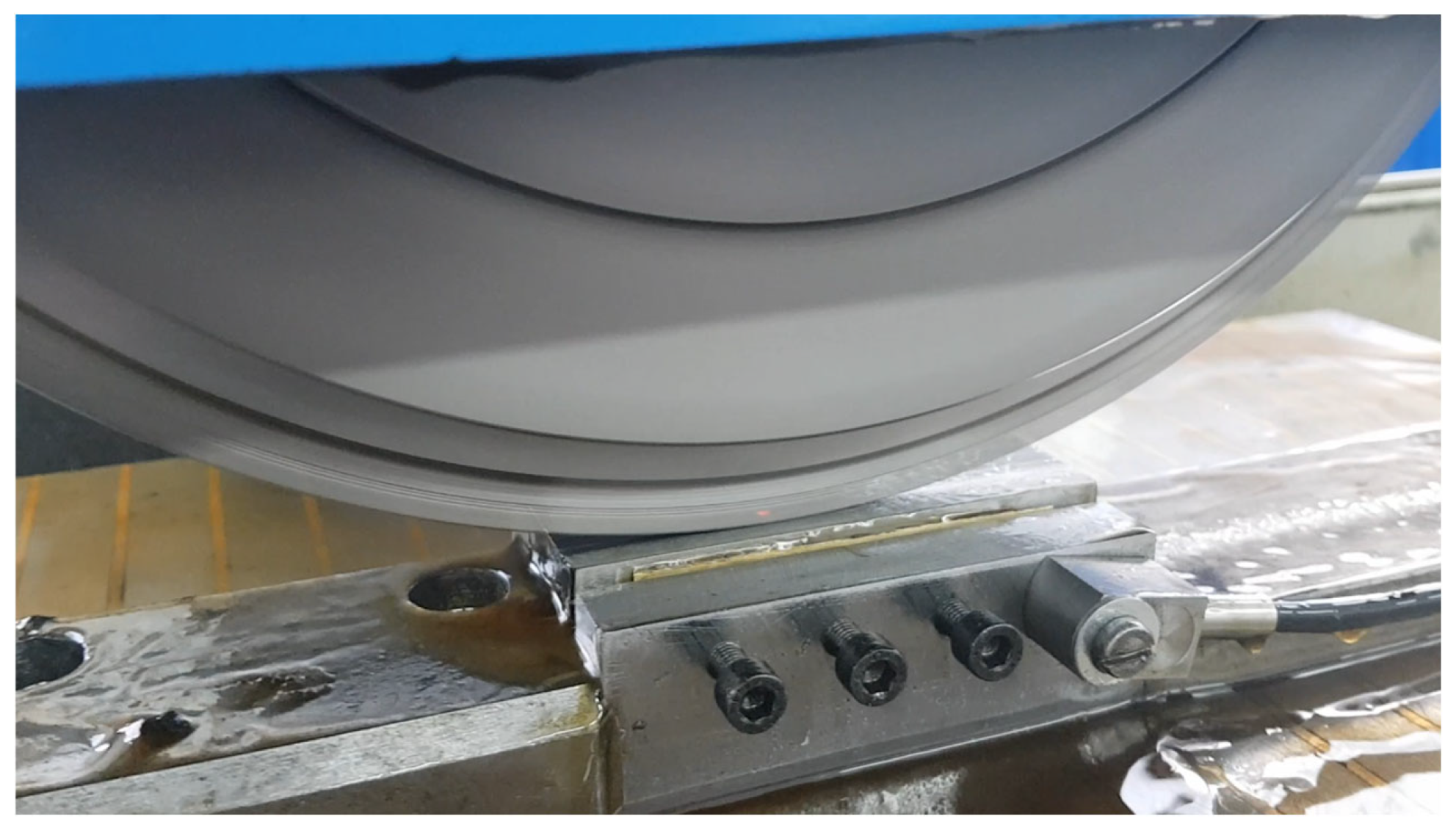
The thermo-deformation treatment (TDT) of the surface of a part produces an extreme heat flow in the contact area between the part and the tool due to the high-speed friction of the tool on the processed surface of a part (Figure 1a). The TDT process combines the following three types of strengthening, namely processing using highly concentrated energy sources, intensive plastic deformation and micro-alloying. The relative velocity between the tool and the part is between 60 and 90 m/s. The tool is pressed on the treated surface of the part with a force of 400–1200 N. The absolute velocity of movement of the sample is 2–10 m/min. The heating rate in the contact area can reach 105–2·106 K/s [50]. During this rapid temperature rise, metal surface layers are heated to temperatures above the phase transformation point (Ac3), (900–1200 °C). After the removal of the energy source, the metal surface layers are rapidly cooled (104–6·105 K/s) due to the transfer of heat to deeper layers of the metal. During high-speed cooling, a condition arises when separate phases have not yet fully developed from the solid solution. A simultaneous high-speed shear deformation of the treated surface also takes place in the contact area. Due to the high-speed heating and cooling and intense shear deformation, nanocrystalline structures, typically visible as a white layer, are formed in the surface layer [51,52]. As for the kinematics of the TDT process, they are similar to that of the grinding process. For the TDT of circular or flat working machine part surfaces, grinding machines with a modernized main drive unit are used. To strengthen the surfaces of revolving parts, customised equipment for installation on lathes has also been developed. For the TDT process to be implemented, it is necessary to ensure a relative linear velocity of 60–90 m/s on the working part of the tool. A metal disk made of structural (Steel C45) or stainless steel (321S12) is used as a tool for the TDT of the machine part surface. The tool dimensions correspond to the size of the grinding wheel, which can be installed on the machine according to its specifications. One of the critical features of TDT is the employment of a process liquid on the surface during the treatment, whose characteristics can affect the resulting material characteristics of the treated surface. In this paper, we investigate the effect of a range of different process liquids on the resulting characteristics. These liquids are directed to the treatment area (zone) using the customised equipment referred to above [53,54].
The cooling of the surface layer during processing is due to the movement of heat into lower depths of the metal of the treated part. The process liquids that are used during the treatment remove only a small portion of heat that is generated in the contact zone of the tool part.
The tool part contact area is locally heated during the TDT due to the high-speed friction of the tool’s working surface on the working surface of the part. The contact area’s dimensions depend on the treated surface shape, the size of the working surface of the tool and the part, the elastic properties of the part material, the components of the interaction forces that arise in the contact area during processing, and the processing conditions (modes). The duration of a single contact and the number of tool passes over the treated surface depend on the processing conditions as well as on the ratio of the width of the tool’s working part to the cross-feed speed.
In the process of thermo-deformation treatment, strengthened, high-quality, solid layers are formed, similar to those during laser, plasma, and ion beam treatments. All the specified treatments refer to strengthening methods using highly concentrated sources of thermal energy of various types. There is a cyclic effect of the intense shear deformation of the surface layer, which contributes to the grinding of the layer structure and is absent in the other indicated processing methods, in addition to the action of a high-concentration thermal energy source during thermo-deformation treatment. For the practical implementation of thermo-deformation treatment, inexpensive tool machines are used, which are available at every enterprise, in comparison with laser, plasma, and ion beam processing, which require expensive equipment. It is possible to more easily micro-alloy the surface layers of the metal of the treated surfaces with various chemical elements, using various technological liquids, pastes, solid elements, etc., during thermoforming treatment.
During laser, plasma, and ion beam treatments, surface alloying of the treated surfaces is performed, using coatings with certain chemical elements, pastes, and other solid or plastic substances. It is not possible to use liquids.
The process liquids tested were as follows: mineral oil (O); mineral oil with active additives containing polymers (AAP); water (W); and an aqueous saturated solution of mineral salts based on magnesium and calcium chlorides (ASMC) (Bischofite). All of these process liquids used during the processing contain hydrogen. To study the impact on the formation of the strengthened layers, the TDT was also carried out without use of a process liquid, as well as with pre-hydrogenated samples. The process liquids are used as a source of chemical elements (carbon, hydrogen, nitrogen, chlorine, silicon and others) to saturate the surface layer during processing and improve the quality of the treated surface. They affect the process of grain crushing and the formation of a strengthened layer.
Machine and tool. TDT of the working surfaces of samples was performed on a modernized flat-grinding machine KNUTH, HFS 3063 VS (Wasbek, Germany) (Figure 1). The engine was arranged to allow the possibility of changing the rotation frequency of the spindle. A metal tool disc is set instead of an abrasive wheel, made of Steel C45 (after normalizing) [55].
Samples. Flat samples with the dimensions 10 × 20 × 100 mm were made of the following materials: Armco-iron (microhardness is 1.5 GPa); Steel C22 (microhardness of 2.51 GPa); Steel C45 (quench-hardening (QH), low-temperature tempering (LTT), microhardness of 4.06 GPa); Steel 41Cr4 (QH, LTT, microhardness of 5.05 GPa); and Steel CT80 (QH, LTT, microhardness of 6.14 GPa) (Figure 2).
The chemical composition of samples is as follows: mass. %: Steel C22 (EN): 0.22 C, 0.50 Mn, 0.27 Si, 0.25 Cr, 0.04 S, 0.3 Ni, 0.035 P, 0.3 Cu, 0.08 As, Fe: balance; Steel C45 (EN): 0.45 C, 0.70 Mn, 0.27 Si, 0.25 Cr, 0.04 S, 0.3 Ni, 0.035 P, 0.3 Cu, 0.08 As, Fe: balance; Steel 41Cr4 (EN): 0.40 C, 0.78 Mn, 0.26 Si, 1.12 Cr, 0.01 S, 0.01 P, Fe: balance; Steel CT80 (EN): 0.8 C, 0.25 Mn, 0.25 Si, 0.2 Cr, 0.028 S, 0.25 Ni, 0.03 P, 0.25 Cu, Fe: balance; Armco-iron (the total impurity content is about 0.16%): 0.025 C, 0.035 Mn, 0.05 Si, 0.025 S, 0.015 P, 0.05 Cu, Fe: balance.
The samples were strengthened by TDT under the following processing conditions: the relative linear velocity of the working part of the tool—70 m/s; the velocity of sample movement—4 m/min; and the pressing force of the tool to the sample—760 N. A double stroke of the tool was used on the treated surface.

3.2. Test Methods

The determination of the microhardness of the surface layers of the studied samples was carried out on a hardness tester QNESS 60 M Evo (Mammelzen, Germany), load—0.5 N.
Metallographic research conducted as part of these investigations showed that during the TDT of Armco-iron using various process liquids, a strengthened nanocrystalline layer of varying thickness and hardness is formed on its surface layer. A cross-section of the samples was made by employing a waterjet cutting machine Water-Jet B 2010, KNUTH (Wasbek, Germany), then polishing and etching using standard technology.
Grain (crystallites) size D of the strengthened surface was determined by X-ray diffractometry DRON-3, using CuKα—radiation (U = 30 kV, I = 20 mA) with a scanning rate of 0.05° and point exposure of 4 s. The diffractograms were processed by CSD software (version 8) [56,57].

4. Results and Discussion

After TDT, a surface layer with a nanocrystalline structure and a crystallite size of 12–60 nm with a misorientation angle of more than 10° is formed on the treated surface. On this surface, the value of crystallites is at the nanoscale (12–20 nm), and the angle of misorientation is the largest. The grain size is different at different layer depths. The grain size increases with increasing depths of the strengthened layer [53].
A strengthened layer (termed a ‘white layer’ due to its appearance) may be formed during intensive processing conditions (such as turning, milling or grinding) and during the operation of heavy-loaded friction pairs. Burn zones may be formed during grinding, which are similar in their structure to white layers and they are a reject form of the processed surface. These burn zones have higher hardness than the base material of the surface and they have the appearance of spots [57,58]. But the primary role of TDT is to form a uniform (solid) strengthened layer on the surface of the machine’s parts. In all cases, a qualitative uniform white layer was studied.
The formation of the structural stress in the metal is significantly influenced by the modes of TDT, the process liquid used, the material and form of the working part of the tool, and other factors.
The surface layer beneath the contact area is intensively heated to high temperatures and intensively cooled down after the tool is removed from the contact area. Large gradients of temperature and stress arise in it. Molecules of the process liquid, which is delivered to the treatment area, are adsorbed onto the treated surface of the part. The process liquid is decomposed into its constituent chemical elements under the impact of high-speed friction in the tool part contact area. Due to the tribodestruction of the hydrogen-containing process liquids, hydrogen is emitted intensely and locally. Due to the intensive friction on the surface of the treated part in the tool part contact area, oxide films are removed and native (clean) surfaces are formed. Extensive electrical and electromagnetic phenomena arise during friction between the contacting surfaces of the parts, resulting in the destruction of water molecules and oils, resulting in the formation of atoms of hydrogen, oxygen, carbon, and other elements. Hydrogen diffuses into the deformed layer. The diffusion rate increases when the gradients of temperature and stress increase [59].
Following process liquid tribodestruction, hydrogen is in an active, ionic, diffusive form and it dissolves readily into the crystalline lattice of the surface layer metal. The hydrogen concentration reaches an equilibrium state, which depends on the temperature, stresses and electric and magnetic fields prevailing in the treatment area. This form of hydrogen is reversible, and in this case, it does not affect the brittleness of the steel [36,60].
In general, hydrogen in metal is known to negatively affect the operability of machine parts due to hydrogen embrittlement. The hydrogen embrittlement of steels occurs due to hydrogen in the molecular state occupying the crystalline lattice defects. The hydrogenation of the metal surface layer during the friction process has no common features with normal hydrogen brittleness, either through the sources of hydrogenation or via the intensity and nature of the hydrogen distribution in the metal [34].
Hydrogen is also known to positively affect the process of the surface treatment of machine parts (plastic deformation, cutting, etc.) by increasing the effectiveness of the process and the quality of the treated surfaces. Research has shown that during the strengthening of Fe-C-H alloys, the presence of hydrogen reduces the temperature of the martensite transformation in iron, which decreases the critical temperature of strengthening. Small amounts of hydrogen have a positive effect on the processes of machining and cutting parts. Hydrogen increases the plasticization of the surface metal layer, facilitates plastic deformation, and improves the quality of the treated surfaces. During the interaction of hydrogen with metal, interconnections between the surface metal atoms are weakened, which promotes the creation of a positive strength gradient from the surface into the deeper layers of the metal. Such a gradient in the surface layer also reduces the coefficient of friction, as well as facilitating the formation of the parts’ working surfaces over the course of cutting and pressure treatment [34,59,61].
Conducted studies have shown that during TDT without supplying a process liquid to the processing zone of samples made of steel with a low carbon content (for example, Steel C22), an intermittent low-quality strengthened layer is formed., The layer is practically not formed when processing Armco-iron samples without a process liquid.
During the treatment with the supply of water (H2O) to the treatment zone, a continuously strengthened layer of small thickness is formed, which is much thinner than the layers obtained using the other investigated process liquids.
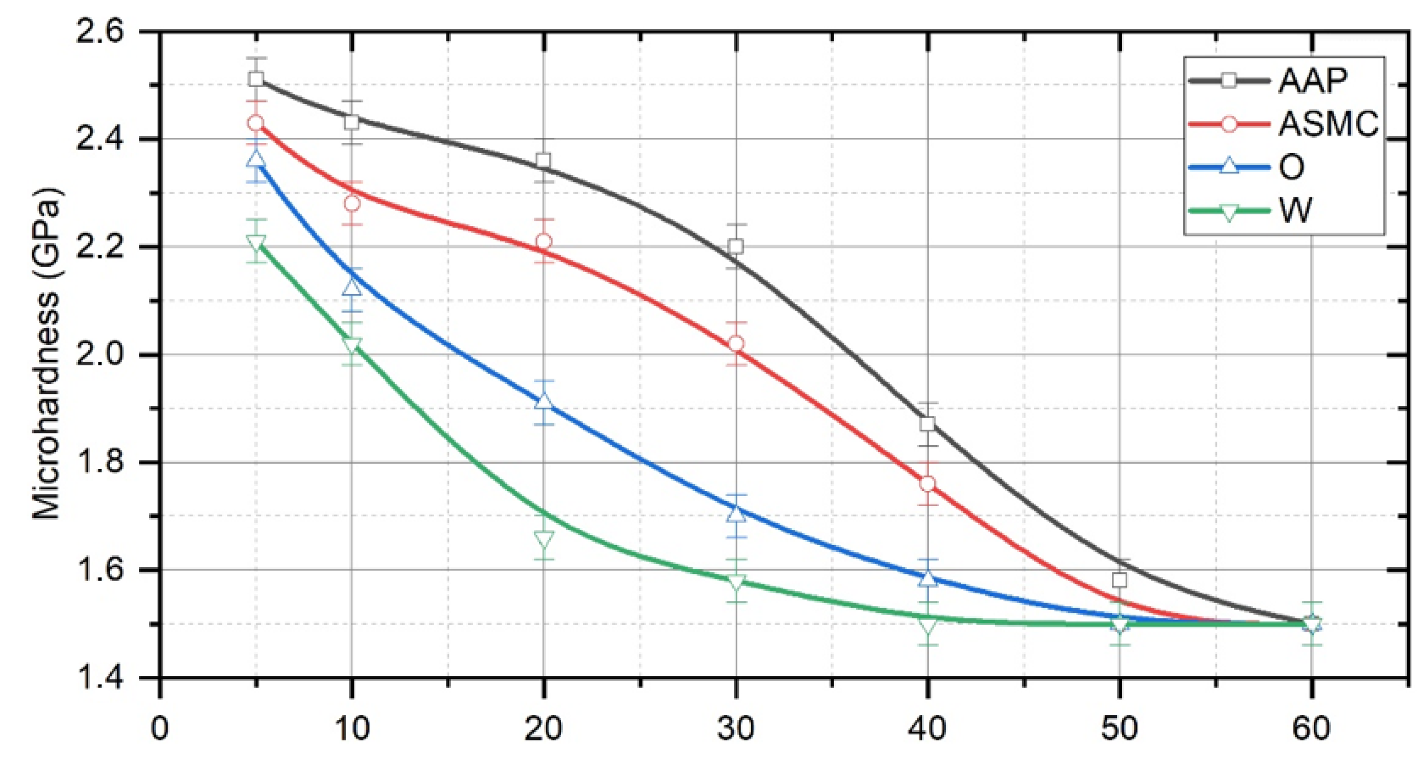
When mineral oil is employed as the process liquid in the contact area, it decomposes into atomic carbon and hydrogen, which diffuse into the part’s surface layers and facilitate the formation of the strengthened layer. The formation of a qualitative strengthened layer is mainly influenced by carbon that diffuses from the process liquid. The layer thickness is about 10–15 μm (Figure 3).
When water is employed as the process liquid, there is no carbon diffusion source from the process liquid, though a strengthened layer is nonetheless formed. Its thickness is the smallest of any of the layers formed by the addition of the process liquids and it is about 5–10 μm. When ASMC is used as the process liquid, the strengthened layer is thicker (15–20 μm) compared to treatment with mineral oil. ASMC contains no carbon compounds either. The strengthened layer of the largest thickness was obtained during the treatment using mineral oil with the AAP process liquid. The layer thickness was about 20–25 μm. During the treatment of the Armco-iron samples without using any process liquids, the strengthened layer is formed intermittently, with an insignificant thickness (less than 5 μm).
The investigation of the microhardness of Armco-iron samples following TDT using different process liquids showed that the greatest value of microhardness (2.51 GPa) was obtained near the treated surface after mineral oil with AAP was used as the process liquid. A slightly lesser microhardness (2.43 GPa) was obtained after using mineral oil (O). The smallest microhardness was obtained after treatment using water alone as the process liquid. Following the TDT of Armco-iron without any process liquid, the microhardness of the treated layer differs only slightly from that of the untreated layer.
Under the influence of high temperatures, the polymer is depolymerized (organic polymers are formed from C–H radicals), i.e., it decomposes into its components, carbon, hydrogen and other elements, which then diffuse into the metal surface layer. The temperature of polymer depolymerization is approximately 300–350 °C, which is not as low than the temperature of the decomposition of mineral oil. Polymers are an additional source of the diffusion of carbon and hydrogen into the metal surface layers of the treated surfaces.
The use of ASMC as the process liquid during the TDT contributes to a significant increase in the thickness and microhardness of the surface layer. Mineral oil with AAP has the greatest impact on the formation of the strengthened layer. The process liquid decomposes into its constituent chemical elements (atomic carbon, hydrogen and others) over the course of the treatment, which diffuse into the surface layer. The ASMC composition lacks carbon, but it contains components that decompose, activate the surface, reduce surface energy and thus produce active hydrogen under the influence of high temperatures and pressures.
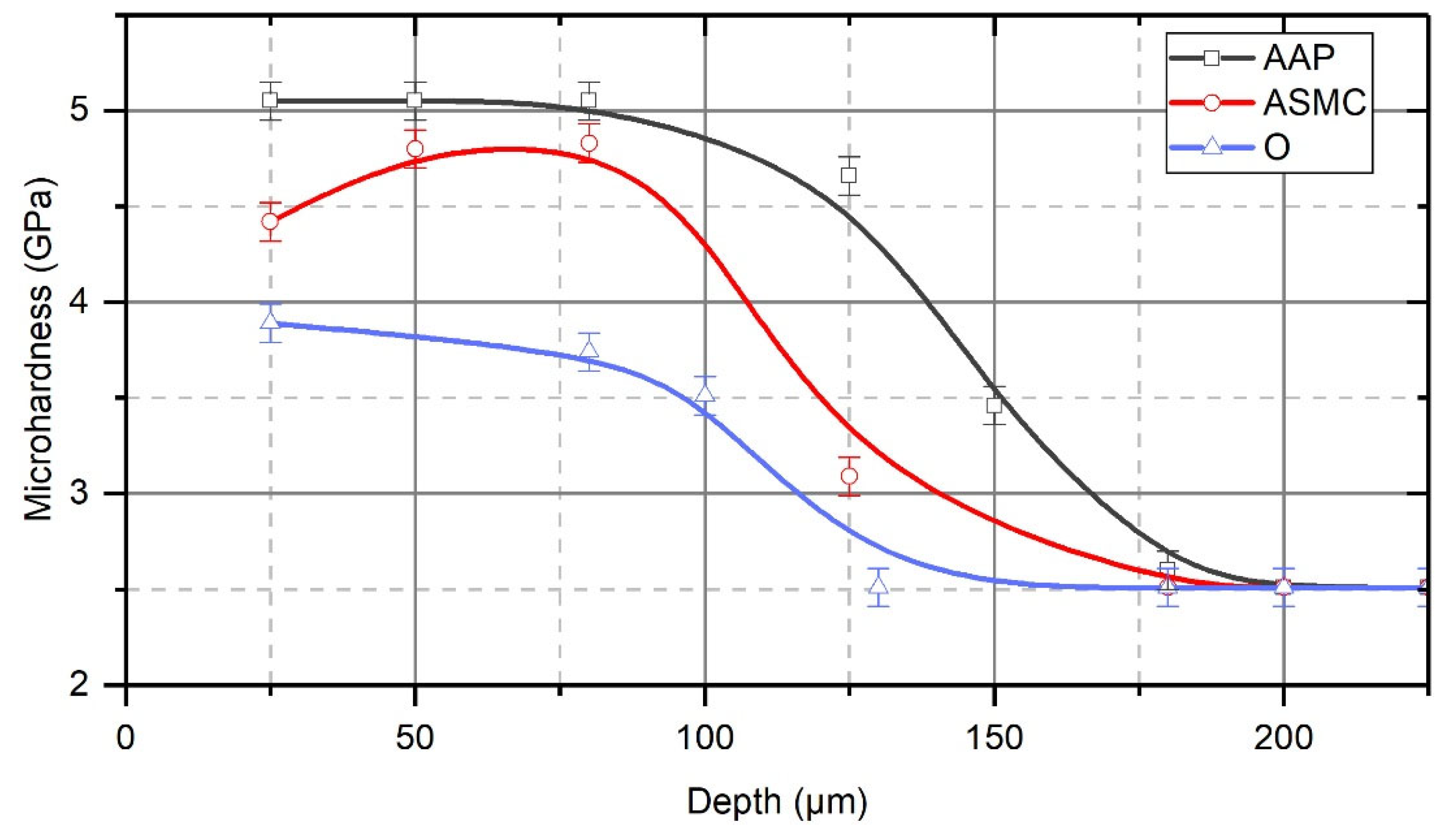
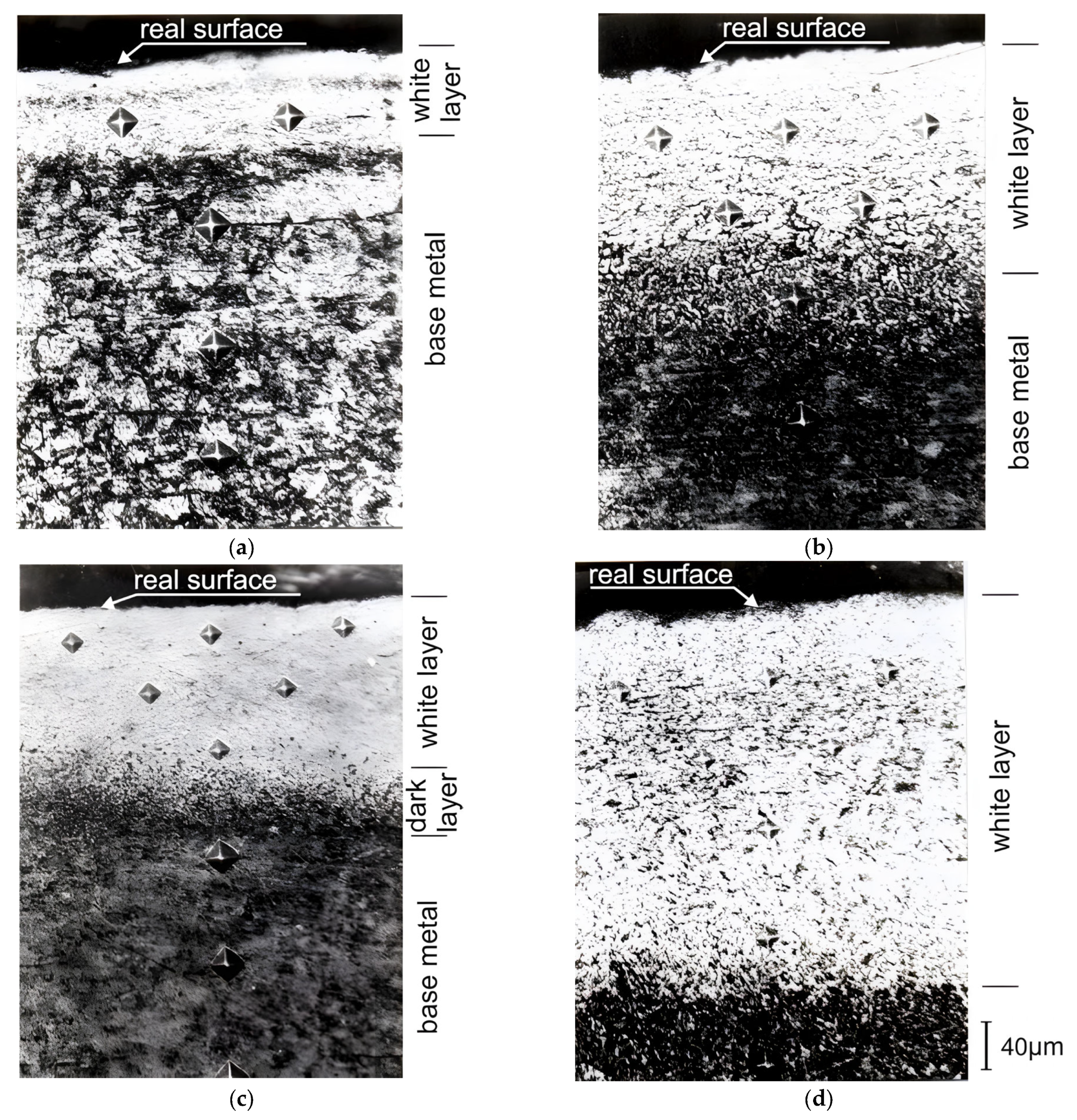
During the TDT of Steel C22 when using mineral oil as the process liquid, the white, strengthened layer forms a relatively thin layer, with a maximum thickness of 40–50 μm. When applying ASMC, the maximum white layer thickness increases sharply to 80–90 μm. The strengthened layer of the greatest thickness and microhardness is obtained when mineral oil with AAP is used as the process liquid. It is even throughout its length, with a thickness of 100–110 μm (Figure 4).
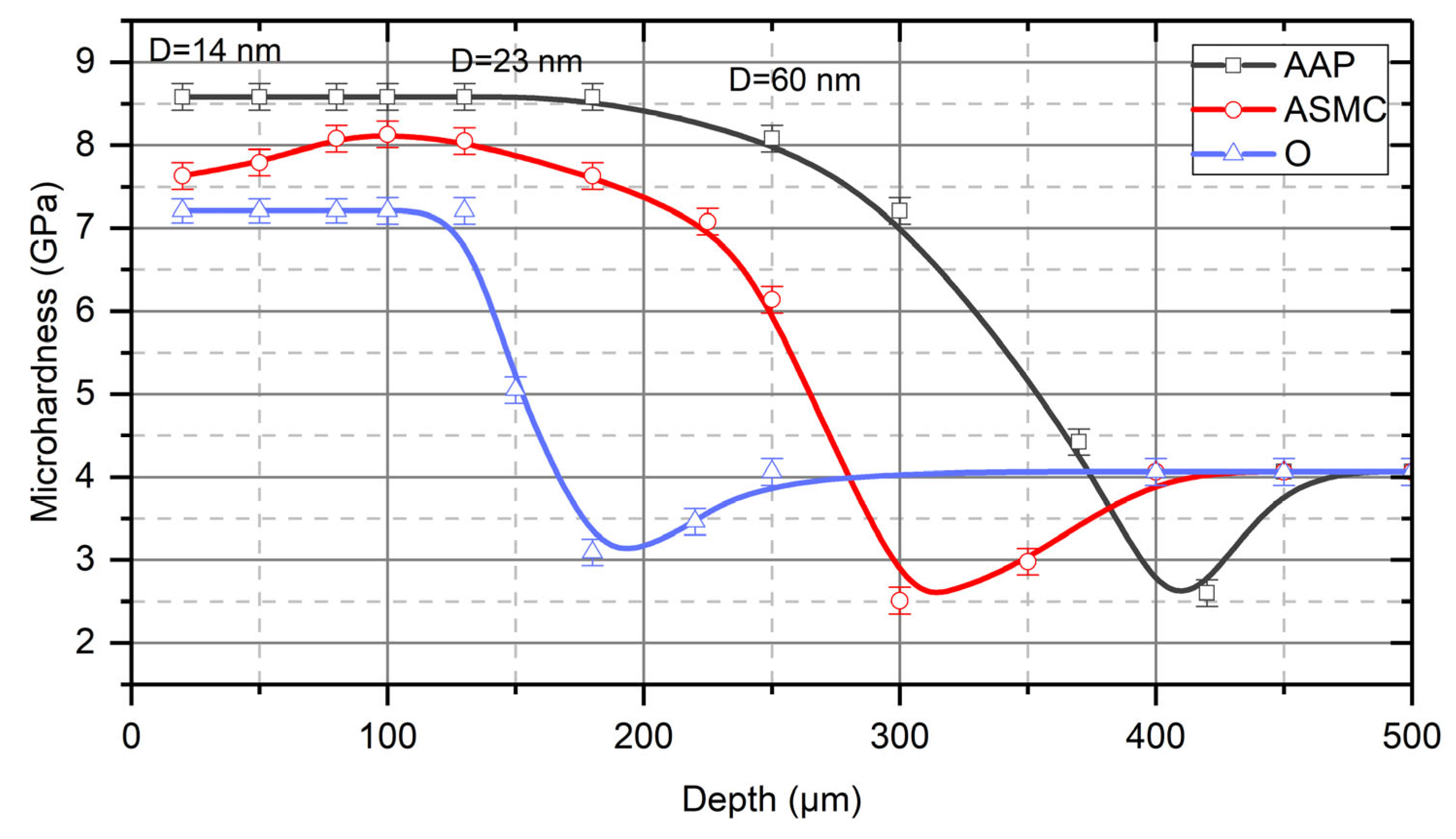
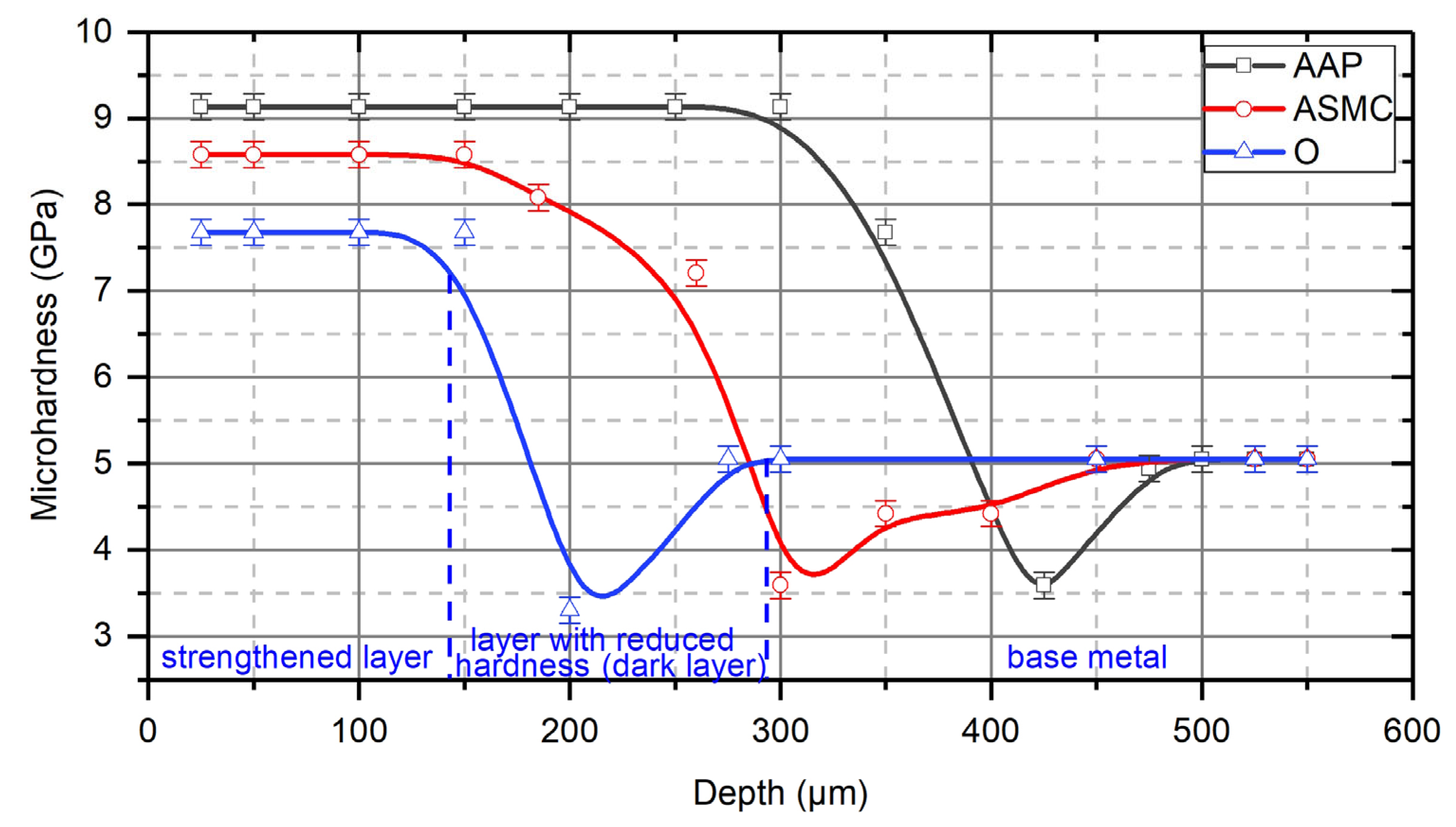
Similar research results were obtained during the TDT of Steel C45 after QH and LTT and Steel 41Cr4 after QH and LTT. Thus, the thickness of the strengthened white layer obtained after the TDT of Steel C45 using mineral oil is 110–120 μm, and if ASMC is used, it increases to 180–200 μm. The largest thickness (230–240 μm) is obtained during treatment using mineral oil with AAP as the process liquid (Figure 5). When Steel 41Cr4 is strengthened with mineral oil, the white layer thickness is 160–180 μm, with ASMC applied it reaches 200–220 μm, and if mineral oil with AAP is used, the value is 260–280 μm (Figure 6).
Studies have shown that after the TDT of samples of Steel C45 using mineral oil with AAP as the process liquid, grain (crystallites) size D on the treated surface is between 12–14 nm [54]. The grain size increases with increasing depths of the strengthened layer, and at a depth of 150 μm, the grain size increases to 23–25 nm. At a depth of 250 μm, which is close to the thickness of the strengthened layer, the grain size becomes 60–65 nm. Beyond this, the grain size increases to the initial value (3–5 μm).
The microhardness of Steel C22 and Steel C45 is substantially influenced by the use of ASMC and mineral oil with AAP as the process liquid during the TDT. Thus, the microhardness of the white layer obtained for Steel C22 using ASMC is 4.4–4.6 GPa, using mineral oil with AAP, it is 5.0 GPa, and using mineral oil, it is 3.8 GPa and 2.5 GPa of the main structure. The greatest value of microhardness is for Steel C45.
After the TDT of Steel 41Cr4 using mineral oil with AAP, the microhardness of the strengthened layer is the largest and equals 9.1 GPa, and if ASMC is used, the microhardness of the white layer is also higher compared to using mineral oil and equals 8.6 GPa and 7.6 GPa, respectively, with the basic structure microhardness equal to 5.0 GPa.
There is an area with reduced hardness and increased etchability beneath the strengthened layer during the TDT of samples made of pre-quench-hardened steel and the LTT.
The application of ASMC and mineral oil with AAP over the course of TDT increases the thickness of the white layer, as well as its microhardness, and the area of tempering with reduced hardness also increases. In this area, the heat flow is insufficient to form a strengthened layer but is sufficient for the high-temperature tempering of the pre-quench hardened metal sample (the samples had QH and LTT before TDT). Therefore, the area of the metal below the strengthened layer after TDT (the white layer) has a lower hardness than the base metal. During etching with a standard etching agent, it becomes darker. Over the course of strengthening non-quench-hardened metal by TDT (after annealing and normalization), the increased etchability zone is not observed. For greater clarity, the location of the zones in the surface layer after TDT using mineral oil (O) is shown in Figure 6.
This research has shown that carbon significantly influences the formation of the strengthened layer. The strengthened layer thickness and microhardness increases with increasing carbon content.
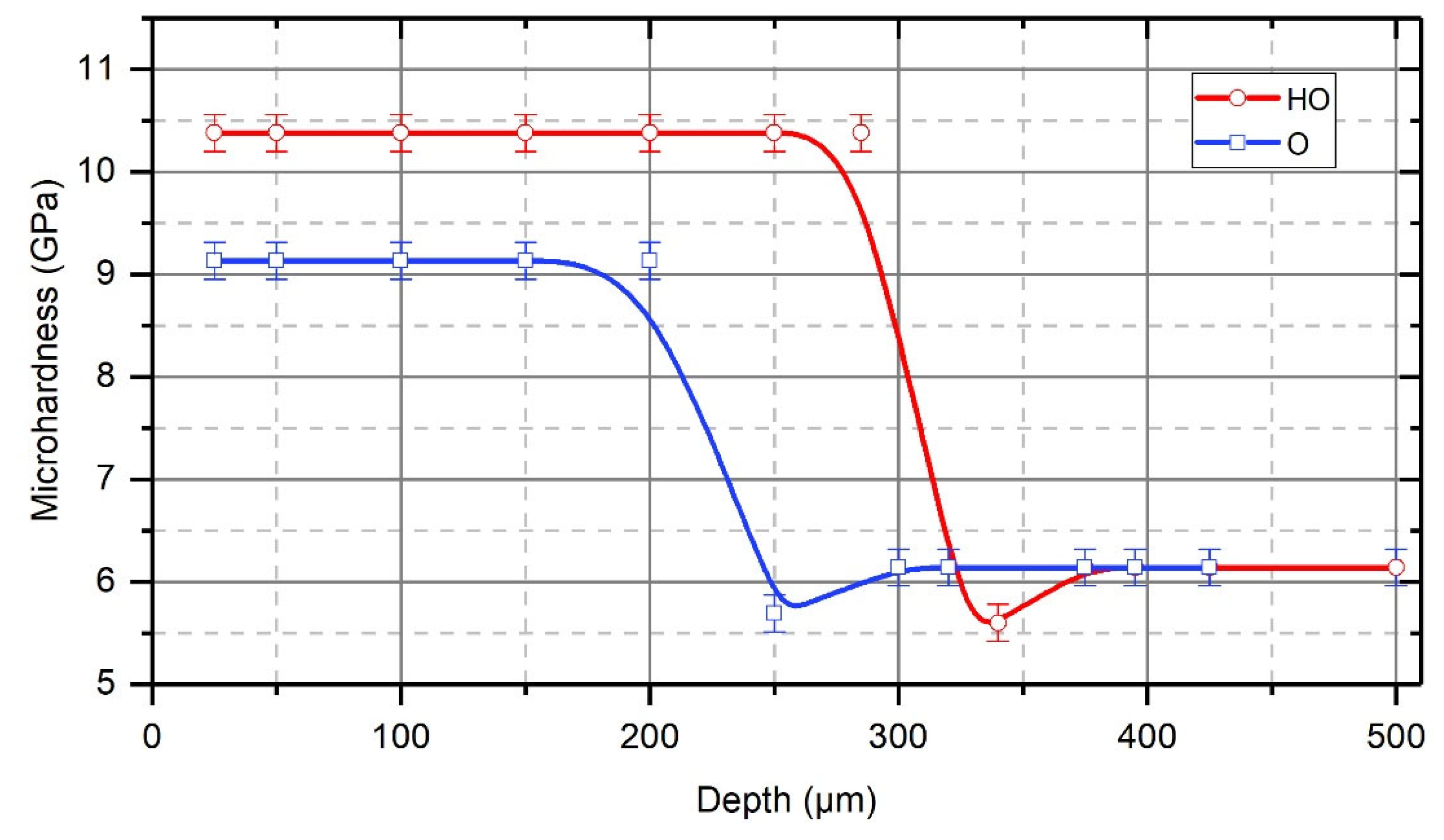
On the other hand, hydrogen also influences the formation of the strengthened layer. To study the influence of hydrogen on the formation of the strengthened layer, pre-hydrogenated samples were strengthened (by TDT). The samples were made of Steel CT80 (QH and LTT), which had a high carbon content (appr. 0.8%) (Figure 7).
The hydrogenation of the surface layer of samples was performed using an electrolytic technique at a current density of 0.1 mA/cm2 in 1% solution H2SO4 + 2.5 g/L thiourea for 60 min. The distribution of hydrogen with depth of the sample was not determined.
A metallographic investigation, Figure 8, showed that the strengthened layer thickness and microhardness increased significantly after the TDT of pre-hydrogenated samples compared to the non-hydrogenated samples. Mineral oil was used as the process liquid. The strengthened layer thickness of the hydrogenated samples increased to 280–290 μm compared to a thickness of 180–200 μm obtained from the non-hydrogenated samples.
Both tensile and compressive strains develop in the surface layers of regions of the tool-part contact area during the course of the TDT (compressive deformations arise in the early contact between the tool and part, and at the end of the contact period, there are tensile deformations), which contributes to hydrogen atom diffusion into the metal. As the temperature rises, the hydrogen solubility and diffusion rate increase sharply. Hydrogen solubility in steels increases by an order of magnitude at polymorphic transformation temperatures [59].
According to references [34,36], the temperature of the martensitic transformation in iron and steels decreases over the course of the QH of Fe-H and Fe-C-H alloys in the presence of hydrogen, the critical cooling velocity decreases during quench-hardening and martensite formation becomes possible even in anhydrous iron at a normal cooling velocity. Hydrogen plasticizes the metal surface layer, improving the processing conditions for its plastic deformation [58,59].
The prominent feature of white layers obtained in medium-carbon steels with a ferrite–perlite structure is the ferrite area observed within the white layer. This confirms the possibility of converting ferrite into austenite with high-speed heating via a diffusionless mechanism [60,62,63,64]. In the process of TDT, which exhibits both high-speed heating and cooling, there is no time for carbon to dissolve in the austenite formed out of the ferrite, and with the succeeding high-speed cooling, it diffusionlessly generates ferrite once again and not martensite. The perlite component has the same transformations as under normal quench-hardening via a diffusion mechanism [46,65]. Perlite transforms into austenite when heated, and martensite is formed when it is cooled. Therefore, the ferrite–perlite structure of the initial metal is less desirable in high-quality strengthened layer formation due to the abrupt change in the carbon content of the structural components in relation to the quench-hardened ones. In order to balance the carbon concentration, it is necessary in this case to have a sufficiently long time lag when heated compared to the quench-hardened structure. Nevertheless, ferrite has a high hardness due to its strong coldwork-hardening, which arises as a result of intense deformation and martensitic transformation [65]. Based on these assertions, it is possible to explain why the white layer obtained in the samples after normalizing has a smaller thickness and microhardness than the white layer obtained in the QH and LTT samples.

5. Conclusions

  • These studies have shown that in the process of the TDT of steel samples, a strengthened (reinforced) nanocrystalline layer is formed in the surface layer. The grain size of the strengthened layer was 12–20 nm near the treated surface, and the misorientation angle was more than 10°. With an increasing depth in the strengthened layer, the size of nanocrystalline grains increases, and at a depth that is close to the thickness of the strengthened layer, the grain size becomes 54–60 nm.
  • The nature of the process liquid used during the TDT significantly affects the thickness of the strengthened layer. The studies have shown that during the TDT using mineral oil with AAP, a uniform strengthened white layer with a nanocrystalline structure of the greatest thickness and hardness is formed on steel samples. Strengthened white layers significantly improve the operational properties of the working surfaces of parts, especially wear resistance.
  • It is speculated that molecules of the process liquid, which is fed into the treatment zone, under the action of high temperatures and pressures decompose into component chemical elements which diffuse into the surface layers of the metal. It is considered likely that carbon, which diffuses into the surface layer, significantly affects the formation of a strengthened layer of greater thickness. It may also be that this strengthening is also caused by thermal or mechanical effects, and an avenue of further work would be to determine which of these mechanisms is the primary cause of the strengthening.
  • Hydrogen, which is evolved in the contact zone from the process liquid due to the friction of the tool on the treated surface of the part, likely diffuses into the surface layer of the part, thus significantly affecting the formation of the strengthened layer. Investigations into the strengthening of Steel CT80 samples showed that after treatment of pre-hydrogenated samples, the thickness of the strengthened layer increased 1.5 times, and the microhardness increased from 9.1 GPa to 10.4 GPa.

Author Contributions

Investigation, I.H., A.A., P.M., A.F., V.G., V.D. and O.P.; conceptualization, I.H., V.G. and V.D.; supervision, I.H.; data collection, I.H., A.A., P.M., A.F., V.G. and V.D.; formal analysis, V.D.; methodology, A.A., P.M. and A.F.; visualization, V.G. and A.A.; data curation: A.F. and V.D.; writing—draft, I.H., A.A., P.M., A.F., V.G. and V.D.; writing—reviewing, I.H., V.G. and O.P. All authors have read and agreed to the published version of the manuscript.

Funding

We gratefully acknowledge funding in the form of EU Grant Nos. [2017-1-UK01-KA107-036029], [2019-1-UK01-KA107-061076] and [2020-1-UK01-KA107-078410], which permitted this collaborative work to take place.

Institutional Review Board Statement

Not applicable.

Informed Consent Statement

Not applicable.

Data Availability Statement

Data is contained within the article.

Conflicts of Interest

The authors declare no conflicts of interest.

References

  1. Santecchia, E.; Hamouda, A.M.S.; Musharavati, F.; Zalnezhad, E.; Cabibbo, M.; El Mehtedi, M.; Spigarelli, S. A Review on Fatigue Life Prediction Methods for Metals. Adv. Mater. Sci. Eng. 2016, 2016, 9573524. [Google Scholar] [CrossRef]
  2. Troshchenko, V.T.; Khamaza, L.A. Stages of Fatigue Failure of Metals and Alloys. Rep. Natl. Acad. Sci. Ukr. 2018, 2, 56–63. [Google Scholar] [CrossRef]
  3. Davis, J.R. Surface Engineering for Corrosion and Wear Resistance; Davis, J.R., Ed.; ASM International: Novelty, OH, USA, 2001; ISBN 978-1-62708-315-7. [Google Scholar]
  4. Yushchenko, K.A.; Borysov, Y.S.; Kuznetsov, V.D.; Korzh, V.M. Surface Engineering; Naukova Dumka: Kyiv, Ukraine, 2007. [Google Scholar]
  5. Pang, J.C.; Li, S.X.; Wang, Z.G.; Zhang, Z.F. General Relation between Tensile Strength and Fatigue Strength of Metallic Materials. Mater. Sci. Eng. A 2013, 564, 331–341. [Google Scholar] [CrossRef]
  6. Madhukar, S.; Harshith Reddy, B.R.; Kumar, G.A.; Naik, R.P. A Study on Improvement of Fatigue Life of Materials by Surface Coatings. Int. J. Curr. Eng. Technol. 2018, 8, 5–9. [Google Scholar] [CrossRef]
  7. Ropyak, L.; Shihab, T.; Velychkovych, A.; Bilinskyi, V.; Malinin, V.; Romaniv, M. Optimization of Plasma Electrolytic Oxidation Technological Parameters of Deformed Aluminum Alloy D16T in Flowing Electrolyte. Ceramics 2023, 6, 146–167. [Google Scholar] [CrossRef]
  8. Quintino, L. Overview of Coating Technologies. In Surface Modification by Solid State Processing; Elsevier: Amsterdam, The Netherlands, 2014; pp. 1–24. ISBN 9780857094681. [Google Scholar]
  9. Lukaszkowicz, K. Review of Nanocomposite Thin Films and Coatings Deposited by PVD and CVD Technology. In Nanomaterials; Rahman, M.M., Ed.; InTech: Houston, TX, USA, 2011. [Google Scholar]
  10. Ropyak, L.; Shihab, T.; Velychkovych, A.; Dubei, O.; Tutko, T.; Bilinskyi, V. Design of a Two-Layer Al–Al2O3 Coating with an Oxide Layer Formed by the Plasma Electrolytic Oxidation of Al for the Corrosion and Wear Protections of Steel. Prog. Phys. Met. 2023, 24, 319–365. [Google Scholar] [CrossRef]
  11. Prysyazhnyuk, P.; Molenda, M.; Romanyshyn, T.; Ropyak, L.; Romanyshyn, L.; Vytvytskyi, V. Development of a Hardbanding Material for Drill Pipes Based on High-Manganese Steel Reinforced with Complex Carbides. Acta Montan. Slovaca 2022, 27, 685–696. [Google Scholar] [CrossRef]
  12. Kaplun, P.V.; Honchar, V.A.; Donchenko, T. V Wear Kinetics of Steels with Diffusion Coatings in Rolling Friction. Mater. Sci. 2020, 56, 50–58. [Google Scholar] [CrossRef]
  13. Klocke, F.; Hensgen, L.; Klink, A.; Ehle, L.; Schwedt, A. Structure and Composition of the White Layer in the Wire-EDM Process. Procedia CIRP 2016, 42, 673–678. [Google Scholar] [CrossRef]
  14. Javaheri, V.; Sadeghpour, S.; Karjalainen, P.; Lindroos, M.; Haiko, O.; Sarmadi, N.; Pallaspuro, S.; Valtonen, K.; Pahlevani, F.; Laukkanen, A.; et al. Formation of Nanostructured Surface Layer, the White Layer, through Solid Particles Impingement during Slurry Erosion in a Martensitic Medium-Carbon Steel. Wear 2022, 496–497, 204301. [Google Scholar] [CrossRef]
  15. Zhang, F.; Duan, C.; Wang, M.; Sun, W. White and Dark Layer Formation Mechanism in Hard Cutting of AISI52100 Steel. J. Manuf. Process. 2018, 32, 878–887. [Google Scholar] [CrossRef]
  16. Olugbade, T.O.; Lu, J. Literature Review on the Mechanical Properties of Materials after Surface Mechanical Attrition Treatment (SMAT). Nano Mater. Sci. 2020, 2, 3–31. [Google Scholar] [CrossRef]
  17. Zhang, F.; Duan, C.; Sun, W.; Ju, K. Effects of Cutting Conditions on the Microstructure and Residual Stress of White and Dark Layers in Cutting Hardened Steel. J. Mater. Process. Technol. 2019, 266, 599–611. [Google Scholar] [CrossRef]
  18. Hosseini, S.B.; Klement, U. A Descriptive Phenomenological Model for White Layer Formation in Hard Turning of AISI 52100 Bearing Steel. CIRP J. Manuf. Sci. Technol. 2021, 32, 299–310. [Google Scholar] [CrossRef]
  19. Xu, Y.; Fang, L.; Cen, Q.; Zhu, J. Nano Structure and Transformation Mechanism of White Layer for AISI1045 Steel during Impact Wear. Wear 2005, 258, 537–544. [Google Scholar] [CrossRef]
  20. Inoue, A.; Hashimoto, K. (Eds.) Amorphous and Nanocrystalline Materials; Advances in Materials Research; Springer: Berlin/Heidelberg, Germany, 2001; Volume 3, ISBN 978-3-642-08664-9. [Google Scholar]
  21. Lei, S.; Liu, Q.; Ma, Y.; Ren, J. Wear Performance of Laser Surface Hardened GCr15 Steel. J. Wuhan Univ. Technol. Sci. Ed. 2010, 25, 84–88. [Google Scholar] [CrossRef]
  22. Bartkowska, A. Production and Properties of FeB-Fe2B-Fe3(B,C) Surface Layers Formed on Tool Steel Using Combination of Diffusion and Laser Processing. Coatings 2020, 10, 1130. [Google Scholar] [CrossRef]
  23. Korzhyk, V.; Tyurin, Y.; Kolisnichenko, O. Theory and Practice of Plasma-Detonation Technology of Surface Hardening Metal Products; Privat Company Technology Center: Kharkiv, Ukraine, 2021; ISBN 9786177319466. [Google Scholar]
  24. Bosheh, S.S.; Mativenga, P.T. White Layer Formation in Hard Turning of H13 Tool Steel at High Cutting Speeds Using CBN Tooling. Int. J. Mach. Tools Manuf. 2006, 46, 225–233. [Google Scholar] [CrossRef]
  25. Vilaça, P. Friction Surfacing. In Surface Modification by Solid State Processing; Elsevier: Amsterdam, The Netherlands, 2014; pp. 25–72. [Google Scholar]
  26. Garcia-Giron, A.; Romano, J.M.; Liang, Y.; Dashtbozorg, B.; Dong, H.; Penchev, P.; Dimov, S.S. Combined Surface Hardening and Laser Patterning Approach for Functionalising Stainless Steel Surfaces. Appl. Surf. Sci. 2018, 439, 516–524. [Google Scholar] [CrossRef]
  27. Huang, X.; Ren, Y.; Zhou, Z.; Xiao, H. Experimental Study on White Layers in High-Speed Grinding of AISI52100 Hardened Steel. J. Mech. Sci. Technol. 2015, 29, 1257–1263. [Google Scholar] [CrossRef]
  28. Wu, S.; Liu, G.; Zhang, W.; Chen, W.; Wang, C. Formation Mechanism of White Layer in the High-Speed Cutting of Hardened Steel under Cryogenic Liquid Nitrogen Cooling. J. Mater. Process. Technol. 2022, 302, 117469. [Google Scholar] [CrossRef]
  29. Guo, Y.B.; Warren, A.W.; Hashimoto, F. The Basic Relationships between Residual Stress, White Layer, and Fatigue Life of Hard Turned and Ground Surfaces in Rolling Contact. CIRP J. Manuf. Sci. Technol. 2010, 2, 129–134. [Google Scholar] [CrossRef]
  30. Saxena, A.K.; Kumar, A.; Herbig, M.; Brinckmann, S.; Dehm, G.; Kirchlechner, C. Micro Fracture Investigations of White Etching Layers. Mater. Des. 2019, 180, 107892. [Google Scholar] [CrossRef]
  31. Dmytrakh, I.M.; Leshchak, R.L.; Syrotyuk, A.M.; Lutyts’kyi, O.L. Influence of the bulk concentration of hydrogen in the metal on the specific features of deformation of low-alloy pipe steel. Mater. Sci. 2014, 50, 170–178. [Google Scholar] [CrossRef]
  32. Ostash, O.P.; Vytvyts’kyi, V.I. Duality of the action of hydrogen on the mechanical behavior of steels and structural optimization of their hydrogen resistance. Mater Sci. 2012, 47, 421–437. [Google Scholar] [CrossRef]
  33. Lynch, S. Hydrogen Embrittlement Phenomena and Mechanisms. Corros. Rev. 2012, 30, 105–123. [Google Scholar] [CrossRef]
  34. Martin, M.L.; Dadfarnia, M.; Nagao, A.; Wang, S.; Sofronis, P. Enumeration of the Hydrogen-Enhanced Localized Plasticity Mechanism for Hydrogen Embrittlement in Structural Materials. Acta Mater. 2019, 165, 734–750. [Google Scholar] [CrossRef]
  35. Tkachov, V.I. Mechanism of Reversible Effect of Hydrogen on Mechanical Properties of Steel. Mater. Sci. 1999, 35, 477–484. [Google Scholar] [CrossRef]
  36. Robertson, I.M. The effect of hydrogen on dislocation dynamics. Eng. Fract. Mech. 2001, 68, 671–692. [Google Scholar] [CrossRef]
  37. Somerday, B.; Sofronis, P.; Jones, R. (Eds.) Effects of hydrogen on materials. In Proceedings of the 2008 International Hydrogen Conference, Jackson Lake Lodge, WY, USA, 7–10 September 2008; ASM International: Novelty, OH, USA, 2009. 766p. [Google Scholar]
  38. Zhang, L.; An, B.; Fukuyama, S.; Yokogawa, K. Hydrogen effects on localized plasticity in SUS310S stainless steel investigated by nanoindentation and atomic force microscopy. Jan. J. Appl. Phys. 2009, 48, 08JB08. [Google Scholar] [CrossRef]
  39. Ren, Y.; Nie, H.; Dong, Y.; Xu, X.; He, J.; Li, Z.; Cai, Z.; Shen, H.; Zhu, M. Fretting wear behavior of different surface modified layers of a tight fit spline used for a gauge-changeable railway vehicle. Tribol. Int. 2024, 193, 109359. [Google Scholar] [CrossRef]
  40. Sun, H.; Wang, Z.; Wang, P.; Chen, C.; Jin, X.; Zhao, X.; Ren, R.; Li, Z.; Zhang, H. An investigation on the formation and hardening mechanisms of white etching layer in hypoeutectoid rail surface. Wear 2023, 530–531, 205010. [Google Scholar] [CrossRef]
  41. Nguyen, B.H.; Camacho, E.T.; Al-Juboori, A.; Ma, Y.; Li, H.; Zhu, H. Tribological behaviors of two distinct classes of white etching layers on rail surface. Wear 2023, 532–533, 205097. [Google Scholar] [CrossRef]
  42. Ribamar, G.G.; Pereira, J.I.; Escobar, J.D.; Avila, J.A.; Lopes, J.G.; Maawad, E.; Schell, N.; Oliveira, J.P.; Goldenstein, H.; Souza, R.M. Microstructure gradients across the white etching and transition layers of a heavy haul pearlitic steel. Mater. Charact. 2024, 210, 113811. [Google Scholar] [CrossRef]
  43. Papazoglou, E.L.; Markopoulos, A.P.; Manolakos, D.E. Experimental research on EDM of AISI O1 tool steel and study of the surface white layer formation. Procedia Struct. Integr. 2018, 10, 235–242. [Google Scholar] [CrossRef]
  44. Zhang, J.; Du, J.; Li, B.; Su, G. Investigation on White Layer Formation in Dry High-Speed Milling of Nickel-Based Superalloy GH4169. Machines 2023, 11, 406. [Google Scholar] [CrossRef]
  45. Hieu Nguyen, B.; Al-Juboori, A.; Zhu, H.; Zhu, Q.; Li, H.; Tieu, K. Formation mechanism and evolution of white etching layers on different rail grades. Int. J. Fatigue 2022, 163, 107100. [Google Scholar] [CrossRef]
  46. Zhang, X.; Wu, D.; Zhang, Y.; Xu, L.; Wang, J.; Han, E.-H. Formation Mechanisms and Crack Propagation Behaviors of White Etching Layers and Brown Etching Layers on Raceways of Failure Bearings. Lubricants 2024, 12, 59. [Google Scholar] [CrossRef]
  47. Schöfer, J.; Rehbein, P.; Stolz, U.; Löhe, D.; Zum Gahr, K.-H. Formation of tribochemical films and white layers on self-mated bearing steel surfaces in boundary lubricated slidingcontact. Wear 2001, 248, 7–15. [Google Scholar] [CrossRef]
  48. Akulovich, L.M.; Galgo, S.I.; Sergeev, L.E.; Babich, V.E. Processing of Materials by Cutting: Educational and Methodological Complex; BSATU: Minsk, Belarus, 2011; 272p. [Google Scholar]
  49. Shaw, L.L. The Surface Deformation and Mechanical Behavior of Nanostructured Alloys. In Nanostructured Metals and Alloys; Woodhead Publishing: Sawston, UK, 2011; pp. 481–506. ISBN 9781845696702. [Google Scholar]
  50. Gurey, V.; Shynkarenko, H.; Kuzio, I. Mathematical Model of the Thermoelasticity of the Surface Layer of Parts During Discontinuous Friction Treatment. Lect. Notes Mech. Eng. 2021, 1, 12–22. [Google Scholar] [CrossRef]
  51. Hurey, I.; Hurey, T.; Lanets, O.; Dmyterko, P. The Durability of the Nanocrystalline Hardened Layer During the Fretting Wear. In Design, Simulation, Manufacturing: The Innovation Exchange; Lecture Notes in Mechanical Engineering; Springer: Berlin/Heidelberg, Germany, 2021; pp. 23–32. [Google Scholar] [CrossRef]
  52. Gurey, V.; Hurey, I.; Hurey, T.; Wojtowicz, W. Fatigue Strength of Steel Samples After Friction Treatment. Lect. Notes Mech. Eng. 2023, 1, 274–283. [Google Scholar] [CrossRef]
  53. Kyryliv, V.; Maksymiv, O.; Gurey, V.; Hurey, I.; Kyryliv, Y.; Zvirko, O. The Mode Deformation Effect on Surface Nanocrystalline Structure Formation and Wear Resistance of Steel 41Cr4. Coatings 2023, 13, 249. [Google Scholar] [CrossRef]
  54. Gurey, V.; Hurey, I. Influence of Surface Hardened Nanocrystalline Layers on the Resistance of Contact Fatigue Destruction. In Proceedings of the Lecture Notes in Mechanical Engineering, Teton, WY, USA, 7-10 September 2008; Ivanov, V., Trojanowska, J., Pavlenko, I., Zajac, J., Peraković, D., Eds.; Springer International Publishing: Cham, Switzerland, 2020; pp. 483–491. [Google Scholar]
  55. Kraus, W.; Nolze, G. POWDER CELL—A Program for the Representation and Manipulation of Crystal Structures and Calculation of the Resulting X-ray Powder Patterns. J. Appl. Crystallogr. 1996, 29, 301–303. [Google Scholar] [CrossRef]
  56. Cullity, B.D. Elements of X-ray Diffraction, 2nd ed.; Addison-Wesley Publishing Company: Boston, MA, USA, 1978; 555p. [Google Scholar]
  57. Cappellini, C.; Attanasio, A.; Rotella, G.; Umbrello, D. Formation of White and Dark Layers in Hard Cutting: Influence of Tool Wear. Int. J. Mater. Form. 2010, 3, 455–458. [Google Scholar] [CrossRef]
  58. Hurey, I.; Hurey, T.; Gurey, V. Wear Resistance of Hardened Nanocrystalline Structures in the Course of Friction of Steel-Grey Cast Iron Pair in Oil-Abrasive Medium. In Design, Simulation, Manufacturing: The Innovation Exchange; Ivanov, V., Trojanowska, J., Machado, J., Liaposhchenko, O., Zajac, J., Pavlenko, I., Edl, M., Perakovic, D., Eds.; Springer International Publishing: Cham, Switzerland, 2020; pp. 572–580. [Google Scholar]
  59. Katzarov, I.H.; Pashov, D.L.; Paxton, A.T. Hydrogen Embrittlement I. Analysis of Hydrogen-Enhanced Localized Plasticity: Effect of Hydrogen on the Velocity of Screw Dislocations in α-Fe. Phys. Rev. Mater. 2017, 1, 033602. [Google Scholar] [CrossRef]
  60. Yasniy, P.V.; Okipnyi, I.B.; Maruschak, P.O.; Bishchak, R.T.; Sorochak, A.P. Toughness and failure of heat resistant steel before and after hydrogenation. Theor. Appl. Fract. Mech. 2011, 56, 63–67. [Google Scholar] [CrossRef]
  61. Yasniy, P.V.; Okipnyi, I.B.; Maruschak, P.O.; Panin, S.V.; Konovalenko, I.V. Crack tip strain localisation on mechanics of fracture of heat resistant steel after hydrogenation. Theor. Appl. Fract. Mech. 2013, 63–64, 63–68. [Google Scholar] [CrossRef]
  62. Fukai, Y.; Sugimoto, H. Diffusion of Hydrogen in Metals. Adv. Phys. 1985, 34, 263–326. [Google Scholar] [CrossRef]
  63. Guzanová, A.; Brezinová, J.; Bronček, J.; Maruschak, P.; Landová, M. Study of selected properties of coatings devoted to extreme tribo-corrosive conditions. Mater. Sci. Forum 2015, 818, 32–36. [Google Scholar] [CrossRef]
  64. Ali Al-Juboori; Huijun Li; Hongato Zhu Formation of white etching layer on rails due to coupled thermal and mechanical actions. Wear 2023, 530–531, 205063. [CrossRef]
  65. Dzyura, V.O.; Maruschak, P.O.; Zakiev, I.M.; Sorochak, A.P. Analysis of inner surface roughness parameters of load-carrying and support elements of mechanical systems. Int. J. Eng. Trans. B Appl. 2017, 30, 1170–1175. [Google Scholar]
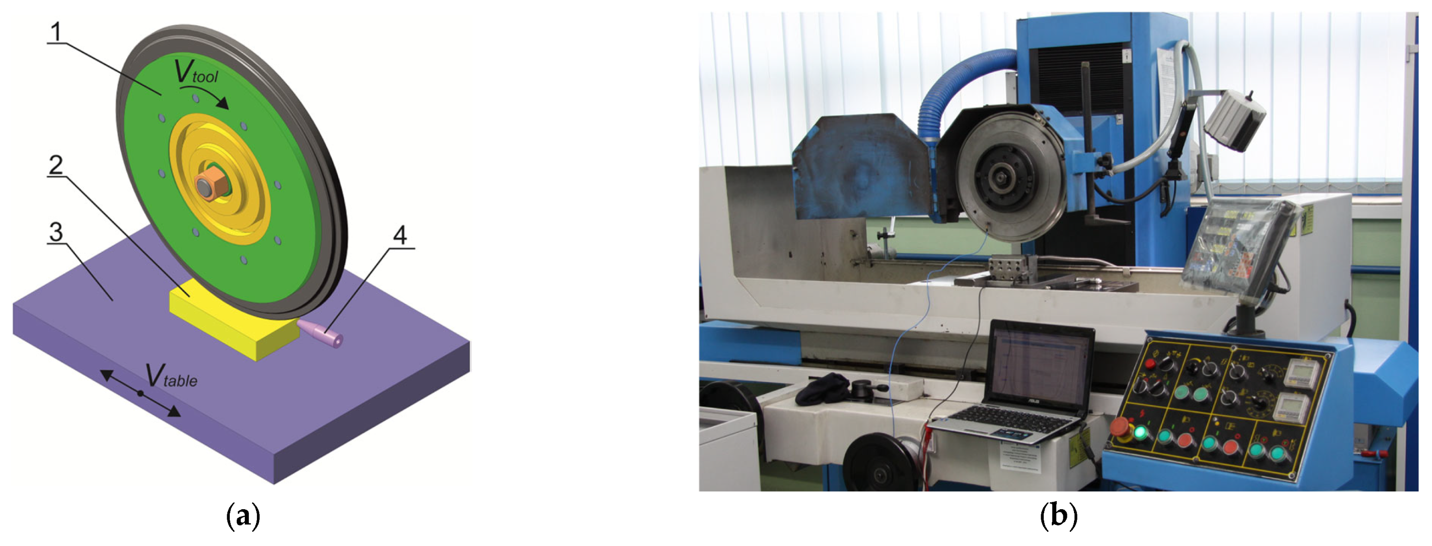
Figure 1. Setup for the TDT process: (a) 1—tool for TDT (disk); 2—sample; 3—grinding machine table; 4—nozzle (to direct process liquid to the treatment zone); (b) grinding machine HFS 3063 VC, KNUTH (Germany).
Applsci 14 08053 g001
Figure 2. The process of strengthening the studied sample.
Applsci 14 08053 g002
Figure 3. Microhardness of Armco-iron using different process liquids: O—mineral oil; AAP—mineral oil with active additives containing polymers; W—water; ASMC—aqueous solution of mineral salts based on magnesium and calcium chlorides.
Applsci 14 08053 g003
Figure 4. Microhardness of Steel C22 using different process liquids: O—mineral oil; AAP—mineral oil with active additives containing polymers; ASMC—aqueous solution of mineral salts based on magnesium and calcium chlorides.
Applsci 14 08053 g004
Figure 5. Microhardness of Steel C45 (QH, LTT) using different process liquids: O—mineral oil; AAP—mineral oil with active additives containing polymers; ASMC—aqueous solution of mineral salts based on magnesium and calcium chlorides.
Applsci 14 08053 g005
Figure 6. Microhardness of Steel 41Cr4 (QH, LTT) using different process liquids: O—mineral oil; AAP—mineral oil with active additives containing polymers; ASMC—aqueous solution of mineral salts based on magnesium and calcium chlorides.
Applsci 14 08053 g006
Figure 7. Microhardness of Steel CT80 (QH, LTT) after TDT without pre-hydrogenated samples (O—mineral oil) and with pre-hydrogenated samples (HO—hydrogen and mineral oil).
Applsci 14 08053 g007
Figure 8. Microstructure of steel, which was formed after TDT: normalized Steel C22, process liquid—(O) mineral oil (a); normalized Steel C22, process liquid—(ASMC) aqueous solution of mineral salts based on magnesium and calcium chlorides (b); Steel C45 (QH, LTT), process liquid—(O) mineral oil (c); Steel C45 (QH, LTT), process liquid—(ASMC) aqueous solution of mineral salts based on magnesium and calcium chlorides (d).
Applsci 14 08053 g008
Table 1. Surface properties with formed white layers of parts of transport systems during their operational and technological formation.
White LayersProperties of the Surface with the Formed White Layers
TechnologyWear
Stability
Resistance
to Cracking
Crack
Resistance
Fatigue
Strength
Intermittent
Solid+++++
Disclaimer/Publisher’s Note: The statements, opinions and data contained in all publications are solely those of the individual author(s) and contributor(s) and not of MDPI and/or the editor(s). MDPI and/or the editor(s) disclaim responsibility for any injury to people or property resulting from any ideas, methods, instructions or products referred to in the content.