Article

Size Dependency of Elastic and Plastic Properties of Metallic Polycrystals Using Statistical Volume Elements

Mechanical, Aerospace, and Biomedical Engineering Department, University of Tennessee, Knoxville, TN 37996, USA
*
Author to whom correspondence should be addressed.
Appl. Sci. 2024, 14(18), 8207; https://doi.org/10.3390/app14188207
Submission received: 6 August 2024 / Revised: 2 September 2024 / Accepted: 10 September 2024 / Published: 12 September 2024
(This article belongs to the Special Issue Structural Mechanics: Theory, Method and Applications)

Abstract

:
We present an efficient approach to evaluate the size dependency of elastic and plastic properties of metallic polycrystalline materials. Specifically, we consider different volume fractions of ferrite and martensite phases for the construction of three macroscopic domains. Statistical Volume Elements (SVEs) of different sizes are extracted from these domains using the moving window method. Linear and Crystal Plasticity (CP) simulations provide elastic and plastic properties of the SVEs such as the bulk and shear moduli, yield strength, and hardening modulus. We use a variation-based criterion to determine the Representative Volume Element (RVE) size of these properties. This RVE size corresponds to a size beyond which the given property can be idealized as homogeneous. We also use anisotropy indices and an additional RVE size criterion to determine the size limits beyond which these properties can be idealized as isotropic. Numerical results show that the plastic properties often reach their homogeneity and isotropy limits at larger sizes compared to elastic properties. This effect is more pronounced for the hardening modulus compared to the yield strength.

1. Introduction

This study investigates the impact of Volume Element (VE) size on the elastic and plastic properties of polycrystalline materials. The mechanical responses of polycrystalline materials are influenced by their microstructural characteristics, including grain size, shape, orientation, and phase distribution. State-of-the-art microstructure characterization techniques enable us to capture statistics of morphological and crystallographic descriptors. The Crystal Plasticity Finite Element Method (CPFEM), a popular choice in which the Finite Element Method (FEM) is used for the solution of Crystal Plasticity (CP) equations, has facilitated the study of size dependency in polycrystalline materials [1]. We can thoroughly understand the influence of these microstructural features by analyzing the material at multiple scales with different volume elements.
Continuum thermomechanics is founded on the concept of the Representative Volume Element (RVE) [2], which is well defined for two cases: (1) a unit cell in a periodic microstructure, and (2) a statistical representative volume containing a large number of microscale elements. Under such conditions, the material in an RVE can be represented in continuum form using classical homogenization approaches to obtain the effective material properties. When an RVE is not well-defined, Statistical Volume Elements (SVEs) can instead be formulated to represent the material in continuum form. For deviation from case 1, e.g., [3,4,5,6], SVEs are used to investigate the perturbations to the geometry and material properties of the periodic unit cell. If the VE is not large enough in case 2, the boundary condition type [7], clustering and position of microstructures [8], and variations to the observation window [9,10] all result in randomness in the SVE. SVE-homogenized properties are referred to as apparent properties. Similar to RVEs, the applied Boundary Conditions are often required to satisfy the Hill–Mandel energy equivalency condition [11].
SVEs provide several advantages in the context of CPFEM for case 2. First, analyzing VEs that are equal to or larger than the RVE size for elastic and plastic properties is often computationally prohibitive given the complexity of CP equations. Second, SVE-based homogenization maintains underlying material inherent randomness and spatial heterogeneity, both of which are important in multi-scale failure simulations [2,12,13]. Efficiency and accuracy are dependent on SVE size when using the moving window method, because apparent homogenized properties are assigned at the centers of the SVEs that traverse the domain [10,14]. If the SVEs are too small, the choice of BCs significantly affects the form and values of the apparent properties. If the SVEs are too large, the randomness and heterogeneities of the properties disappear as the SVE size tends to the RVE size.
The RVE size is an important parameter that determines the size beyond which a property is homogeneous, size-independent, and/or isotropic (when applicable) depending on the criterion [13,15]. The RVE size for a given property can be determined by an analysis of apparent properties for varying SVE sizes. One popular approach is to determine the RVE size when the coefficient of variation in the homogenized properties over all VEs falls below a user-defined tolerance [16]. Alternatively, calibration of an empirical power relation eliminates the need to simulate an RVE-size VE. Rather, the extrapolation of the best fit estimates the RVE size. This approach is particularly useful for CP simulations, when the simulation cost of RVE size domains can be prohibitively high.
For various ductile materials, the RVE size is needed in the prediction of elastoplastic and viscoplastic properties [17,18,19,20]. The required number of grains for microstructure and property-based statistically equivalent RVEs were determined through the creation of virtual microstructures and the application of finite element simulations [21,22]. The RVE size for a single-phase polycrystalline pure copper was determined for 3D polycrystalline pure copper with computational homogenization [23,24]. RVE size for monotonic and cyclic loading was determined for single-phase polycrystals with full-field computational homogenization using CPFEM [25,26,27]. However, the study of size dependency using the moving window and SVE approach within CPFEM is a recent idea.
There are many aspects that affect the RVE size and, in general, the size dependency of a material and its corresponding formulated models. The existence of an internal length scale in a material model is a major source of size dependency due to its interaction with the domain size. Examples include gradient and generalized elasticity models [28], non-local [29] and gradient [30] damage models, and phase field fracture models [31,32]. Another influence is the stochastic nature of material microstructure, i.e., (micro)crack, void, and grain distribution. As the domain size increases, the likelihood of encountering more critical defects increases, resulting in another form of size effect [33].
When modeling the plasticity response, the grain size significantly contributes to various size effects. In general, intrinsic factors such as the grain size, dislocation density, grain boundary effects and the domain size as an extrinsic factor result in size dependency [34]. For example, smaller grains have been shown to increase material strength by restricting dislocation motion [35,36,37]. As previously mentioned, internal length scales also introduce a size effect. CP models, however, are often devoid of such length scales. Because gradients in strain are particularly significant near grain boundaries and interfaces, the use of CP models in combination with internal length scales and gradient effects is advocated [38].
The goal of this study is to evaluate the size dependency of elastic and plastic properties of two-phase polycrystalline materials. SVE-based statistical homogenization is performed in a CPFEM framework for ferrite and martensite materials with varying volume fractions. Convergence rates for different properties are evaluated through a statistical study to determine the size dependency and calculate the RVE limits.
The size effects study is focused on the stochastic nature of material microstructure, Specifically grain orientation and phase distribution. The size effect due to grain size is not significant when the grain size distribution is constant across all analyses [35], as in our study. Moreover, Ref. [39] has shown that the effect of the internal length scales diminishes as the domain size becomes 10 to 100 times larger than the internal length scale. The grain size is typically the length scale in CP models [34,38,40]. In this research, the smallest domain is 10 times larger than the grain size, therefore, excluding the internal length scale effects is reasonable herein.

2. Methods

It is essential to integrate microstructure characterization and continuum mechanics methods to predict and understand the effects of microstructure on macroscale behavior. DREAM.3D, Neper, and other microstructure reconstruction software can generate virtual microstructures [41,42,43]. The mechanical response of these microstructures can then be simulated in the CPFEM framework [1,44].

2.1. Generation and Partitioning of Microstructural Domains

We constructed microstructural domains consisting of two distinct phases: ferrite and martensite. Ferrite is softer and more ductile with a lower yield strength compared to martensite. In contrast, martensite is harder and more brittle. The combination of these two phases creates a heterogeneous microstructure that mimics the complex behavior of different dual-phase polycrystalline materials. We analyzed three different combinations of microstructural domains, each with a different volume fraction of martensite, V f = 10%, 45%, and 90%, identified as Material-1 (M1), Material-2 (M2), and Material-3 (M3). For each volume fraction, 30 microstructures similar to those shown in Figure 1a–c are reconstructed. Each phase within the microstructure consists of multiple grains (Figure 1d), where the grains have distinct size and shape distributions specific to each phase. We considered an average grain equivalent diameter of d ¯ = 5 μ m with an equiaxed shape for both phases. Each grain has a uniform orientation assigned through a random Orientation Distribution Function (ODF). The DREAM.3D v6 software [42] was used for the generation of microstructures. The generated dual-phase polycrystalline domains were measured as 400 μ m × 400 μ m with a thickness of 1 μ m.
The moving window method is a technique to analyze spatially varying properties within a composite material [10,14,45]. This method involves sliding a defined window across the domain (Figure 2). Each window is analyzed using an SVE to obtain the homogenized properties. These properties are assigned to either the entire area of the window or its center, which creates a localized representation of material characteristics. SVE sizes of 50 μ m, 100 μ m, 200 μ m, and 400 μ m were used to partition the 400 μ m × 400 μ m microstructural domains. We employed space-filling uniform square partitions, which ensure that each SVE occupies its designated area without overlap or gaps, adhering to the Huet hierarchy of bounds [46]. SVEs of sizes L SVE = 50 μ m, L SVE = 100 μ m, L SVE = 200 μ m, and L SVE = 400 μ m fill the space of each microstructure with corresponding grids of 64 ( 8 × 8 ) , 16 ( 4 × 4 ) , 4 ( 2 × 2 ) , and 1 ( 1 × 1 ) SVEs, respectively (Figure 2).

2.2. Crystal Plasticity Constitutive Equations

Crystal plasticity theory explains the anisotropic and heterogeneous nature of polycrystalline materials. The main CP equations relevant to this work are
γ ˙ α = γ ˙ 0 τ α τ c α n sign τ α Power law slip model
Δ τ c α = β H β α Δ h β Voce hardening
Δ h β = h 0 1 τ c β S s m γ ˙ β Δ t Hardening evolution
where γ ˙ α , τ α , and τ c α denote the shear strain rate, resolved shear stress, and critical resolved shear stress, respectively, for the slip system α . H β α is the hardening relation matrix corresponding to τ c α . Model parameters h 0 , S s , and m are hardening rate, saturation slip strength, and hardening exponent, respectively. Δ t represents the time increment. We refer the readers to [44,47] for further discussion on these CP equations. Material parameters are assigned individually to each grain within the microstructure rather than to the phases as a whole. Both phases are considered as cubic crystal symmetry. The constitutive model parameters, taken from [48,49,50,51], are provided for each phase in Table 1.

2.3. Apparent Elastic Properties

We consider the in-plane elastic and plastic properties of the SVEs shown in Figure 2. Each SVE undergoes three load cases corresponding to tension in the x-direction, tension in the y-direction, and x y shear loading conditions. A Mixed Boundary Condition (MBC) similar to [52] is used in the x-y plane. That is, in normal directions to the four facets Dirichlet BC (displacement BC) are assigned, whereas for the tangential directions Neumann BC (traction BC) is reinforced. A similar mixed BC is also used on the bottom and top facets with normals parallel to the z-axis. That is, u z = 0 and σ z x = σ z y = 0 . As detailed in [53], mixed BCs are an appropriate choice for homogenization as they provide stiffness values that are between the upper limit Kinematic Uniform Boundary Condition (KUBC, all applied displacements) and lower limit Static Uniform Boundary Condition (SUBC, all applied tractions) solutions.
The homogenized elasticity constitutive equation in Voigt notation is
σ ¯ = C γ ¯ , for σ ¯ = σ ¯ x x σ ¯ y y σ ¯ x y and γ ¯ = ε ¯ x x ε ¯ y y 2 ε ¯ x y ,
where σ ¯ and γ ¯ are the average stresses and strains. The apparent elasticity tensor C is obtained by satisfying Equation (2) for all three loading conditions.
The in-plane bulk modulus is
κ = 1 S 11 + S 22 + 2 S 12
where S = C 1 is the compliant matrix. Other elastic properties (Young’s modulus, E and shear modulus, G) are computed from the isotropic C iso obtained by the angular average of C over all in-plane rotation angles [13,54]. Different anisotropy measures are available to measure the isotropy and directionality of elastic properties [13,55,56,57,58,59,60]. We adopted the Ranganathan–Ostoja anisotropy index [57,58] A RO to describe the anisotropy of elasticity tensor.

2.4. Apparent Plastic Properties

For the plastic properties, the yield surface and its evolution through accumulation of plastic strain for arbitrary loading scenarios (e.g., different combination and orientation of principal stresses) is characterized. However, this requires an exceptionally large number of SVE simulations and analysis of the evolution of strain and stress tensors. Moreover, square SVEs introduce unwanted angular biases [15], which to some extent can be resolved by using circular SVEs [54,61].
Because we use square SVEs, with 0 and 90 degree loading angles we avoid the angular bias issues that arise from loading along all directions [15]. Accordingly, we only consider load cases 1 and 2 from Section 2.3, corresponding to tensile loading in x and y directions, respectively. To characterize the plastic behavior, we determined the 0.2% offset yield strength and the slope of the plastic part of the stress-strain curve for each load case. The calculated yield strengths and plastic hardening pairs are denoted by ( Y x , H x ) and ( Y y , H y ) for x and y directions, respectively. Following [62], for the analysis of the homogeneity and isotropy of plastic properties we introduce,
f : = f x + f y 2 ,
A f : = f x f y f ,
where the undecorated f in Equation (4a) also refers to the average of x and y components and Equation (4) is applied to hardening modulus H and yield strength Y. For an isotropic response for property f, A f = 0 . Moreover, the mean value f from Equation (4a) is used to analyze the overall size dependency of plastic properties.

2.5. Mesh Sensitivity and Element Size

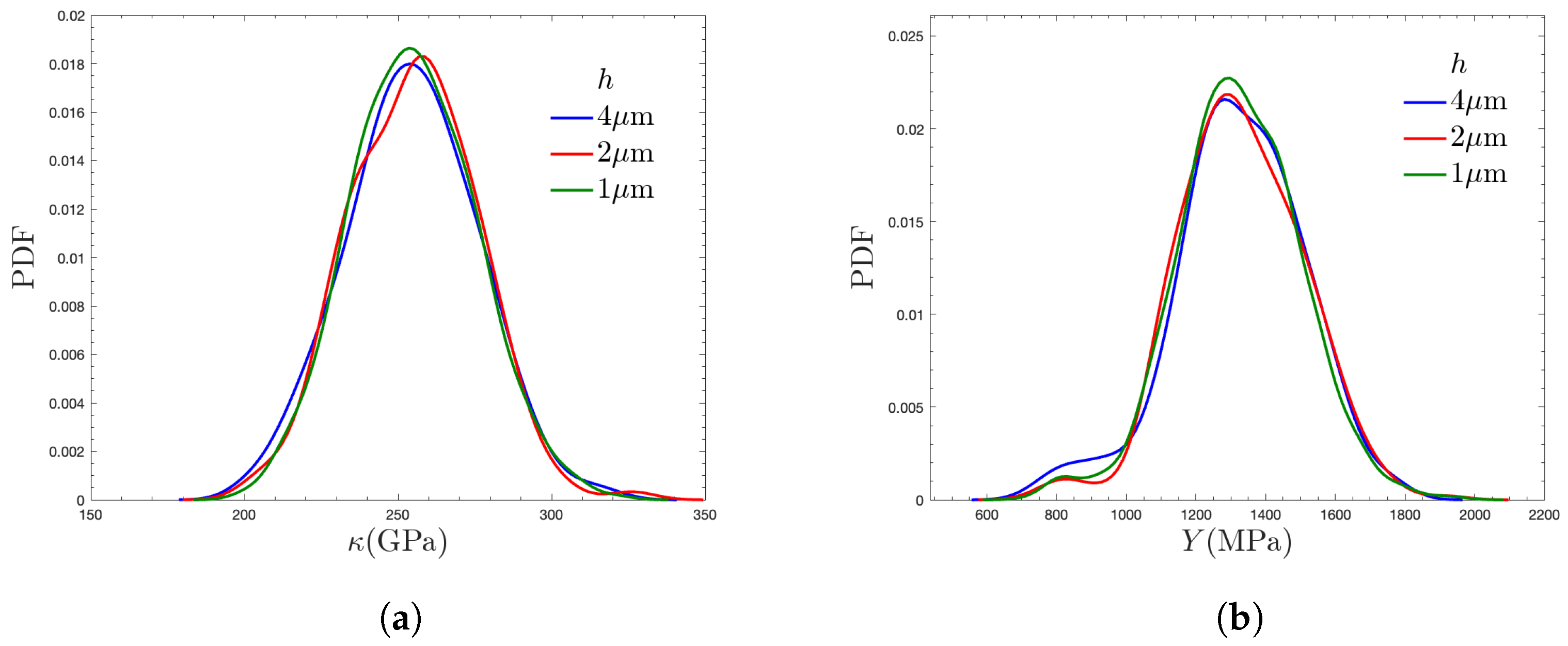
A mesh sensitivity study was conducted for M2 and L SVE = 50 μ m to evaluate the impact of varying element sizes ( h = 4 , 2 and 1 μ m) on elastic and plastic responses. Figure 3 illustrates that the Probability Density Functions (PDFs) for both bulk modulus, κ , and average yield stress, Y, remained consistent across all element sizes and converged as h is refined. This behavior indicates that the results were stable and not significantly influenced by element size. The finer mesh ( h = 1 μ m) was chosen for the analysis to provide a high-resolution representation of the material.

2.6. Size Effect Relations and Convergence to the Rve Limit

We denote the mean and standard deviation of a property f by f ¯ and D f , respectively. The coefficient of variation is defined as c f = D f / f ¯ . For a variation-based analysis, the RVE is determined as the SVE size beyond which the variation (standard deviation D f or coefficient of variation c f ) falls below a user-specified tolerance ϵ . When the variation in a field is below a limit, the field can be considered homogeneous. The standard deviation is used for non-dimensional fields, whereas the coefficient of variation is used for dimensional fields. Examples of the first group are the anisotropy indices and volume fraction and examples of the second group are the bulk modulus and yield strength. If f is ergodic and stationary, an empirical relation is proposed to approximate the decay of variation in f as in [16],
D f ( L SVE ) = b f L SVE α f
D f ( Δ D f ) = ϵ Δ D f = b f ϵ 1 / α f
c f ( L SVE ) = b f L SVE α f
c f ( Δ c f ) = ϵ Δ c f = b f ϵ 1 / α f
where b f and α f are the power scaling factor and convergence rate, respectively. Equations (5) and (6) are used for non-dimensional and dimensional quantities, respectively. The RVE size is denoted by Δ . The linear regression of the logarithm of variation quantity D f ( L SVE ) versus the logarithm of c f ( L SVE ) provides the parameters b f and α f , hence the RVE size. A similar power relations in the form f ¯ ( L SVE ) = f ¯ + b f ¯ / L SVE α f ¯ can be used to determine how the mean value of a homogenized field tends to its terminal value f ¯ (if it exists) when L SVE tends to infinity.
While we do not analyze the corresponding mean-based RVE size [13,15] for all properties, we need to use it to determine anisotropy indices. For the materials considered, the anisotropy indices tend to be zero for L SVE as the materials are macroscopically isotropic. Thus, by setting f ¯ = 0 , the mean-based RVE size for anisotropy indices is obtained as f ¯ ( L SVE ) = ϵ Δ f ¯ = ( b f ¯ / ϵ ) 1 / α f ¯ for f = A RO , A Y , and A H . By setting the isotropic limit as the maximum of mean-based and variation-based RVEs Δ f : = max ( Δ f ¯ , Δ D f ) , we ensure that both the mean and variation in the anisotropy index are smaller than the tolerance ϵ , thus indirectly stipulating that the overall anisotropy index of a material is close to zero for SVEs larger than Δ f . Similar to [13,15], we use this approach to define the isotropy size limit of the apparent properties.

3. Results and Discussion

The apparent homogenized properties of the three different materials are compared. First, in Section 3.1 the geometric volume fraction is investigated. Second, in Section 3.2 the elastic behavior is compared and the effect of SVE size is discussed. Plastic yield strength and the hardening modulus are presented in Section 3.3. The anisotropy of apparent elastic and plastic behavior at smaller SVE sizes is discussed in Section 3.4. The results from the previous sections are summarized in Section 3.5 by elaborating on the form of homogenized effective material parameters.

3.1. Geometric Property

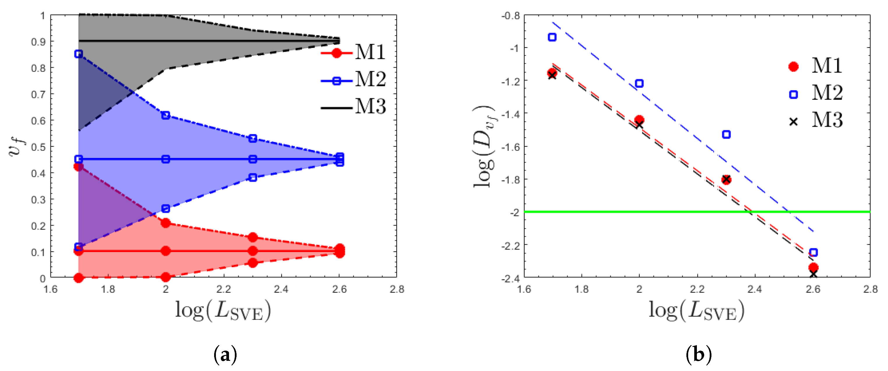
The martensitic volume fractions in the generated 400 μ m × 400 μ m domains of M1, M2, and M3 are V f = 10%, 45%, and 90%, respectively (Figure 1). However, the volume fraction of martensitic phase in an SVE, v f , can have a different value. For example, in smaller SVEs, v f can vary significantly due to local heterogeneity. As the size of an SVE increases, the distribution of v f narrows and approaches a delta function with the center at V f . Figure 4a shows the mean, maximum, and minimum volume fractions observed for all the considered SVE sizes. The solid, dot-dashed, and dashed lines denote the mean, max, and minimum values, respectively. The variation in volume fractions is the largest in small SVEs and the variations in v f gradually decrease as the SVE size increases. The mean values are equal to V f (M1: = 0.10, M2: 0.45, and M3: 0.90) for any SVE size of a specific material, as any SVE size of the same material covers the entire domain. Figure 4b represents the power relations for convergence of the variation in volume fraction. The plot is given in the log-log form with a base of 10 and the horizontal green line represents the RVE limit with tolerance ϵ = 0.01 . Linear regression lines are fitted to obtain the parameters of Equation (5). The data describing the variation-based convergence of RVE limits for different materials are provided in Table 2.
A few conclusions can be drawn from the size dependency of D v f . First, we observe that the D v f of M2 is larger than that of M1 and M3, while the values for M1 and M3 are 246.57 and 237.76, respectively. This relationship is expected from the theoretical results on additive properties such as volume fraction in [63,64], where it is shown that the standard deviation of volume fraction for a volume element is proportional to its point-wise variation, that is V f ( 1 V f ) . This expression takes its largest value of 0.5 for V f = 0.5 , 0.4975 for V f = 0.45 (M2), and the values for V f = 0.1 (M1) and V f = 0.9 (M3) are 0.3. This relationship explains the observed trends. The same theoretical models [63,64] also describe the slope of convergence, a v f as d / 2 , where d is the spatial dimension. In [16,63,64], the variance of a property is related to the SVE volume and the convergence rate for additive properties is 1. In [13] the relation of such an equation to (5) and the power of d / 2 for additive properties is explained. For the spatial dimension of 3 in this study, a convergence rate of 1.5 is predicted. The size of SVEs in the thickness direction was not increased; therefore, it is expected that their response fall between 2D (convergence rate of 1) and 3D (convergence rate of 1.5), settling at convergence rates ranging from 1.3 to 1.4 (Table 2).

3.2. Elastic Properties

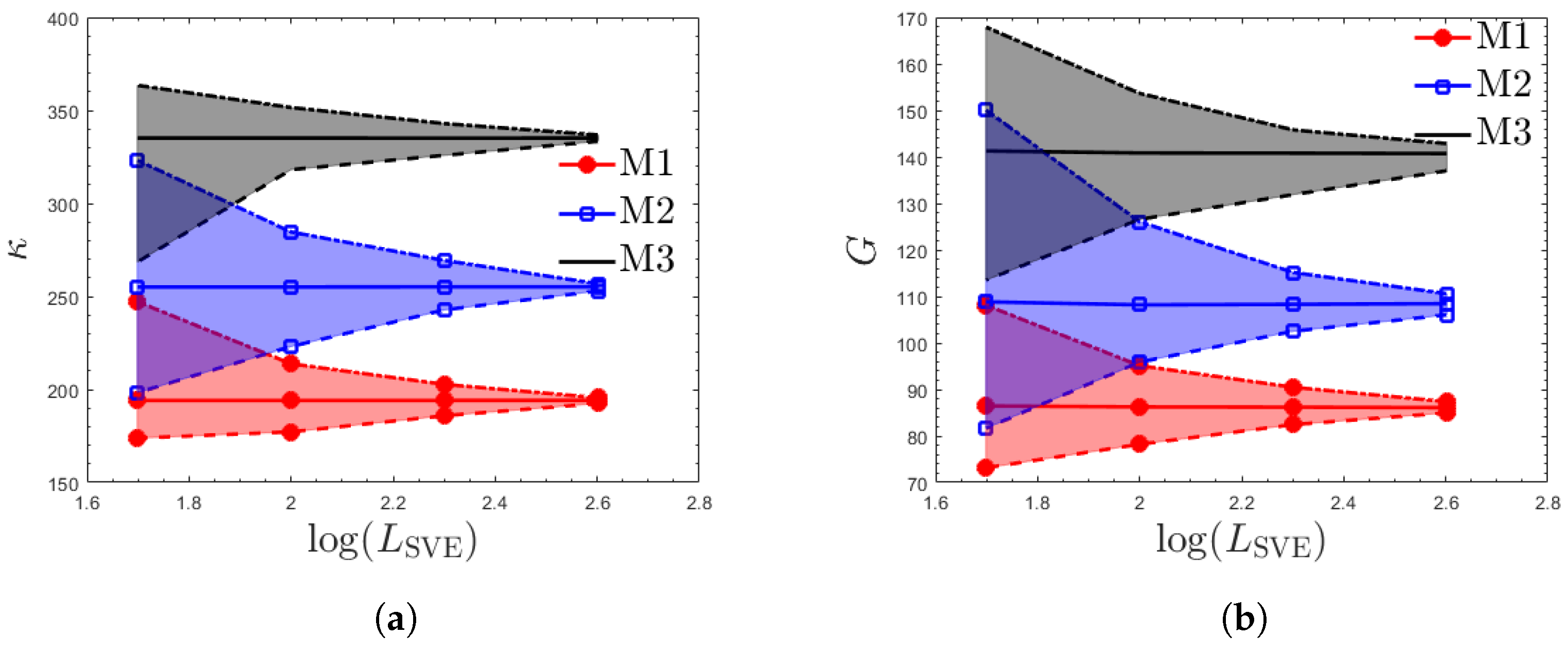
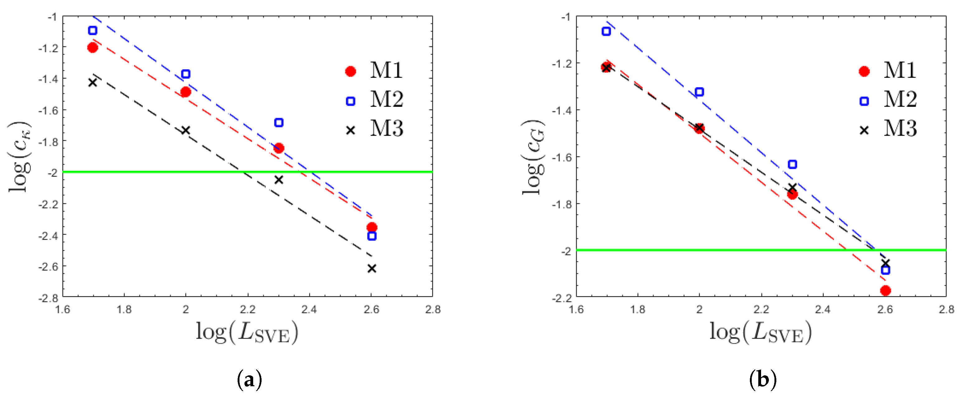
The apparent elastic properties are related to the SVE size. The mean, minimum, and maximum values for elastic properties ( κ , G) are shown in Figure 5 for each material. The smaller SVE sizes have a greater range of values than larger ones. Interestingly, mean values exhibit minimal variation across all SVE sizes of the same material. The mean values for κ are approximately 194 GPa, 255 GPa, and 335 GPa for M1, M2, and M3, respectively. The fact that M3 has a higher mean for homogenized properties can be explained by the fact that M3 has the highest volume fraction of the stiffest martensitic phase. Figure 6 and Table 3 show the power relation results corresponding to Equation (6). Overall, bulk modulus has similar convergence powers, α f , across all v f (Table 2). The shear modulus corresponds to a smaller α f (and large RVE size) than the bulk modulus. This trend is in agreement with the results in [16], where the same observations are made for κ and G and, in general, it is noted more that complex responses (e.g., shear versus hydrostatic response) have larger RVE sizes.

3.3. Plastic Properties

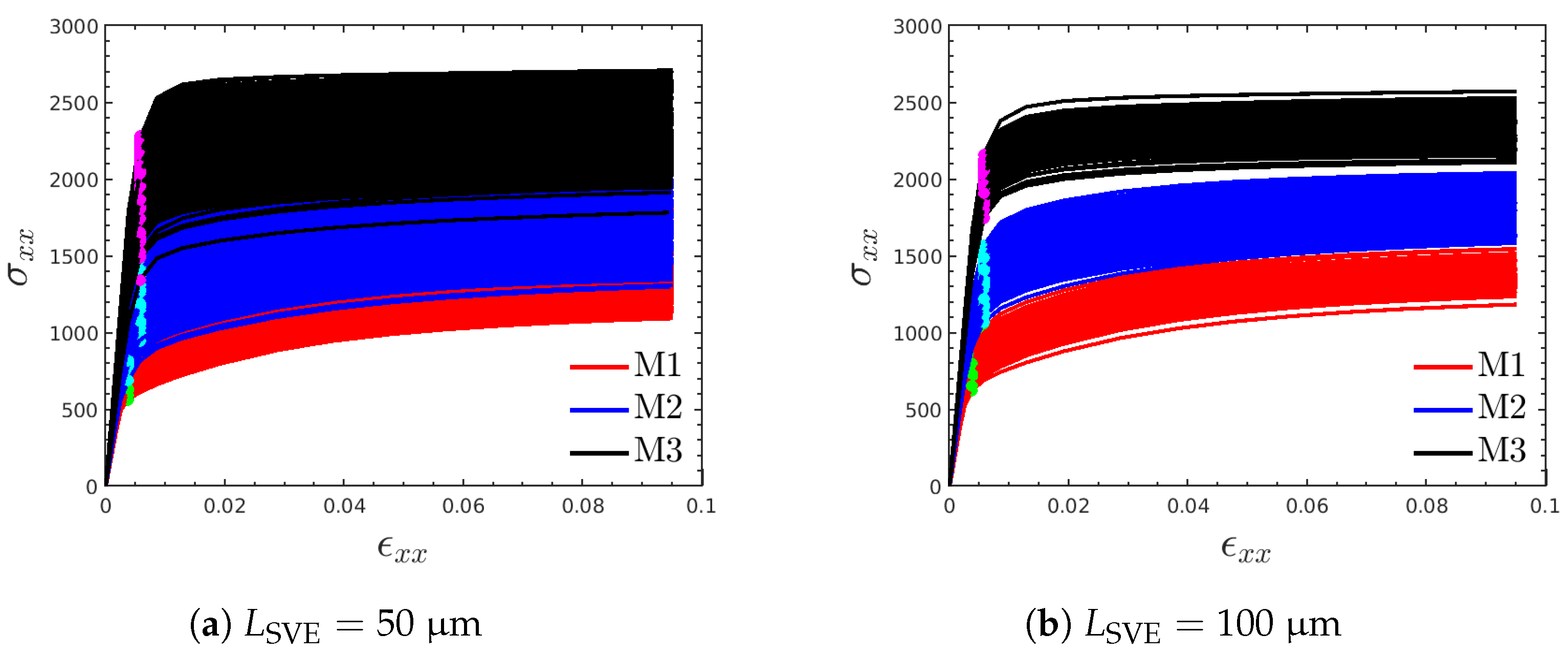
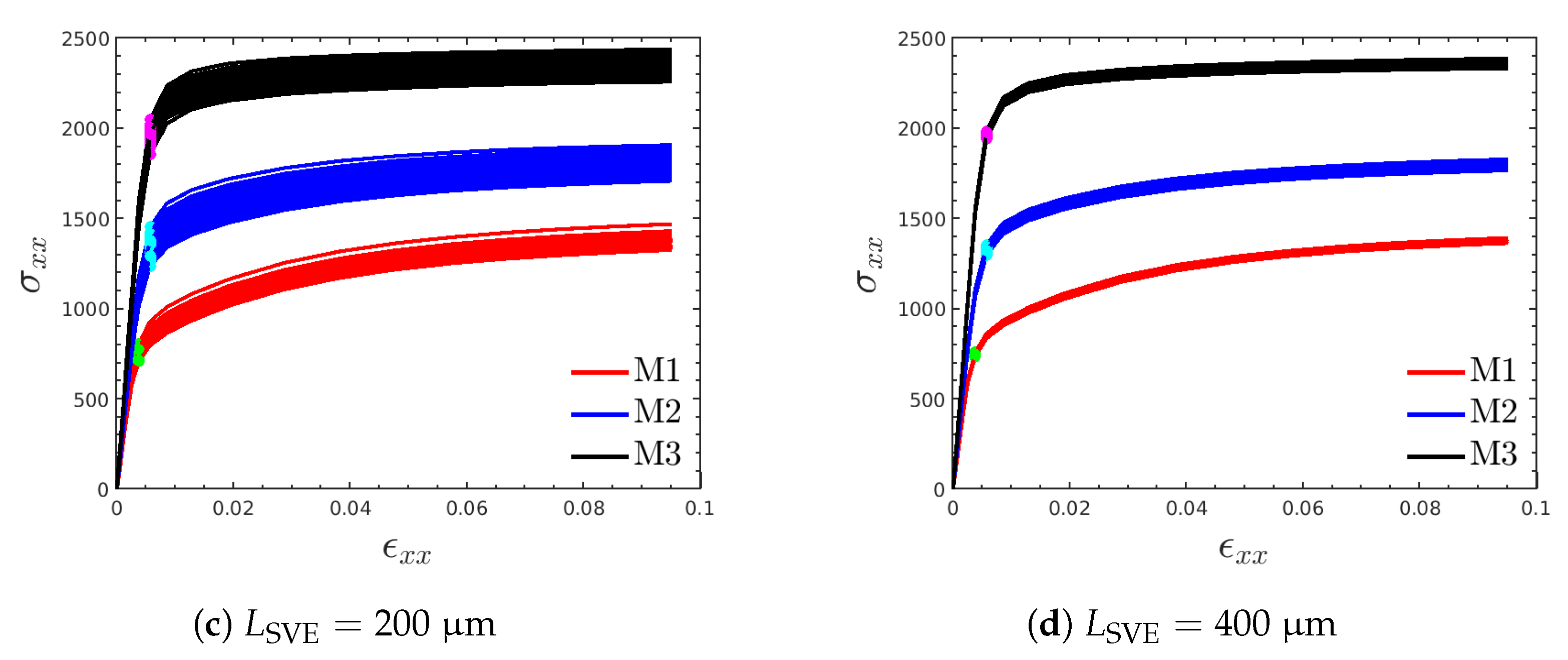
The size dependency of apparent plastic properties is now investigated based on the MBC form of BCs (explained in Section 2.3). The applied displacements on the facets of the SVE gradually increase until the macroscopic stress responses pass a maximum value and tend to zero beyond this stage. Figure 7 shows homogenized σ x x versus ε x x for each SVE size, when the SVEs are loaded along the x-direction (load case 1). The yield strength, Y x , and plastic hardening modulus, H x , are calculated from the homogenized curves for different loading cases using the process explained in Section 2.4. The statistical variation in the overall strain stress response and yield point location decreases as the SVE size increases.
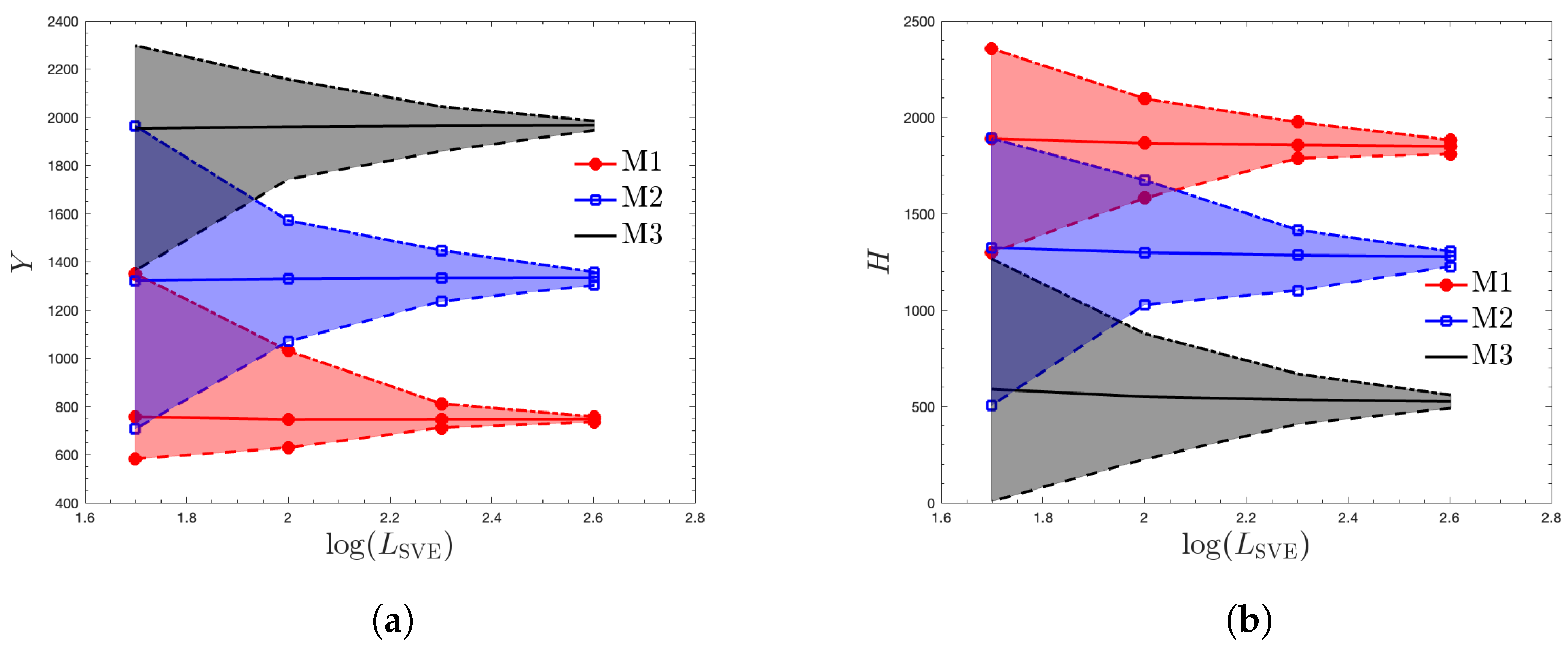
Figure 8 shows the mean, minimum and maximum values of the yield strength, Y, and the plastic hardening modulus, H, obtained by averaging the corresponding x and y load case values; cf. Equation (4a). Similar to elastic properties, the variation in the initial yield strength decreases as the SVE size increases. Similarly, mean properties over the SVE sizes exhibit minimal variations even for the smaller sizes of the same material. However, one interesting observation is the ordering of Y and H values across the three materials; the yield strength ordering in Figure 7c is the same as those of κ and G in Figure 5, as the martensite phase is not only stiffer but also has a higher saturation slip strength; cf. Table 1. The ordering, however, is reversed for H as M1 has the highest homogenized hardening modulus.
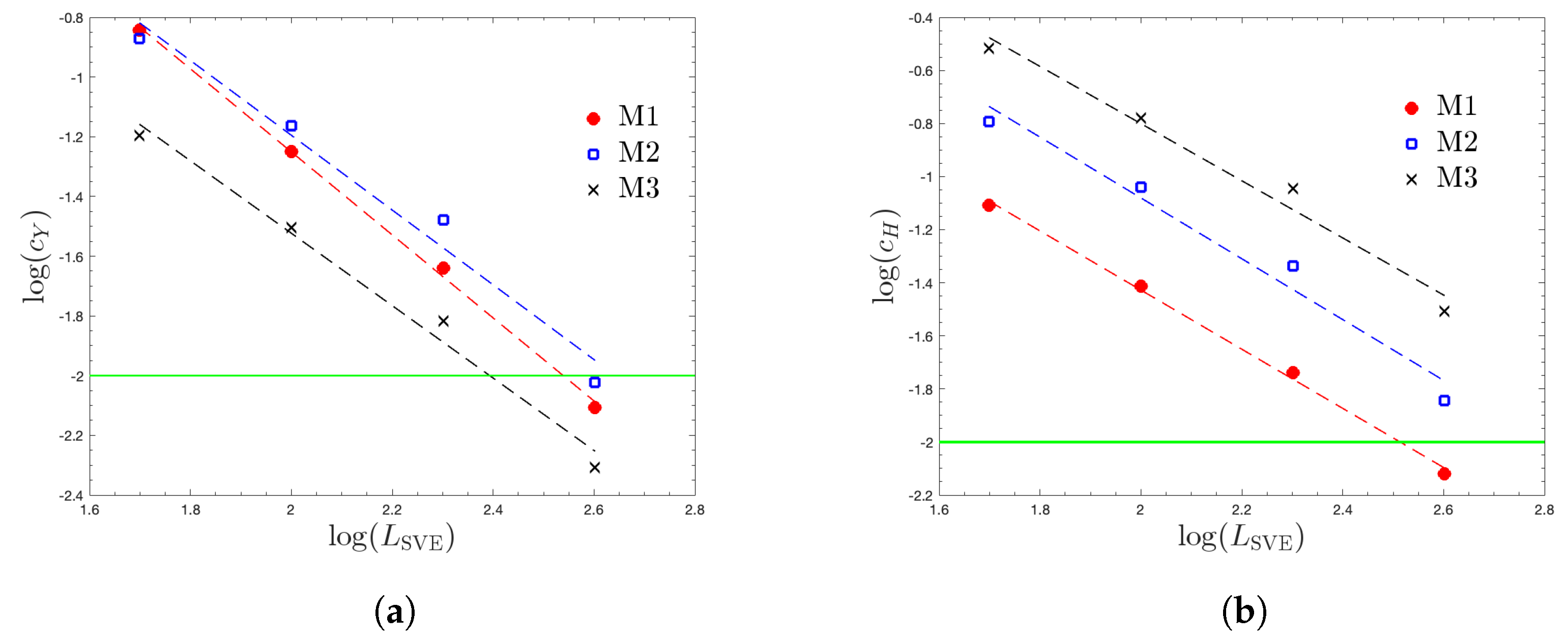
The convergence plots for the RVE limit of plastic properties are shown in Figure 9. Table 4 summarizes the corresponding data. In terms of convergence rate α f , there is no consistent trend when comparing the elastic (Table 3) and plastic properties. That is, the convergence rate for elastic properties is higher for only some properties and materials. However, in terms of RVE size, the elastic properties consistently have a smaller RVE size. This observation is consistent with [16] where it is stated that more complex phenomena have larger RVE sizes, based on thermal conductivity and linear elastic stiffnesses results. In our case, we deem plastic properties to stem from the more complex constitutive equations, cf. (Equation (1)), and the larger RVE size mainly stems from larger proportionality factors, b f (Table 4).

3.4. Anisotropy of Elastic and Plastic Properties

The mean, maximum, and minimum of anisotropy measures are presented in Figure 10. A few observations can be discerned regarding the anisotropy of the elasticity stiffness tensor C , based on the Ranganathan–Ostoja anisotropy index A RO . First, a semi-analytical model [57] shows that for a given L SVE and a composite formed by two isotropic phases, the anisotropy index is zero for V f = 0 and 1 and becomes the most anisotropic for V f around half (the exact value depends on the bulk and shear moduli of the two phases). In this case, we observe higher anisotropy values (especially maximum values) for M2 which is consistent with the model in [57]. Second, we observe that some SVEs have negative values for A RO . We attribute this to the nature of MBC wherein the Hill–Mandel condition is not exactly satisfied. As expected, this discrepancy diminishes as the SVE size increases. We note that this form of MBC [52] is popular as it provides an elasticity tensor that is between the upper KUBC and lower SUBC limits. Moreover, the roller nature of the BCs allows the formation of through cracks (or failure zones) along the width of the SVE in nonlinear simulations. Given that the latter is important in our CP simulations, we chose this BC for linear analysis as well. We refer the reader to [53] for the class of materials, e.g., orthotropic materials, for which the Hill–Mandel condition is exactly satisfied for MBC.
The anisotropy indices for plastic yield strength and hardening modulus are shown in Figure 10b and Figure 10c, respectively. The elastic anisotropy and yield strength anisotropy exhibit similar trends and converge to the isotropic limit. Because the hardening modulus has a complex behavior, its anisotropy index decreases more slowly versus L SVE . The convergence of the anisotropy index to zero for all properties is expected, because at the macroscale the two-phase materials are isotropic. As mentioned in Section 2.6, the isotropy limit of a property is taken as the maximum of mean-based and variation-based RVE sizes for the corresponding anisotropy index. The power relations for this variation-based condition for A RO , A Y , and A H are shown in Figure 11a, Figure 11b, and Figure 11c, respectively. The convergence of mean values to zero follows a similar power relation. Hence, for brevity, the corresponding plots are not included. Table 5 summarizes the variation-based and mean-based parameters and the corresponding isotropy size limits. The isotropy size for the elasticity tensor and yield strength Y are much smaller than that for the hardening modulus H. Given the highly nonlinear nature of the response in the stress hardening regime, the later tendency of H to the RVE size compared to Y (Section 3.3) and here the isotropy size limit is justified.

3.5. The Form of Homogenized Properties

The derivation of apparent elastic and plastic properties not only has merit on its own in terms of understanding the size dependency of properties but can also provide mesoscopic mechanical properties in a numerical multiscale framework. There are two options for the values of these mesoscopic properties in a macroscopic domain. In option one, the macroscopic domain is covered by moving windows and at the center of each window (SVE) its apparent homogenized properties are used as local material properties. In option two, the statistics of the apparent homogenized properties are computed first. The advantage of this approach is that the properties of new macroscopic domains can be assigned by generating random fields that are consistent with such statistics, e.g., one- and two-point statistics of the apparent properties. We refer the reader to [10,65,66] for some examples of these direct and random field options.
We collectively refer to all attributes such as homogeneity, isotropy, and other aspects such as size-dependency (discussed in [13]) as the form of the material properties. For either of the options above, the form of the homogenized field has a direct effect on the accuracy and complexity of the multiscale approach. For large enough SVEs, the homogenized fields become homogeneous and isotropic depending on a material’s microstructural design. The multiscale modeling of such RVE-based properties is straightforward but the lack of heterogeneity and randomness (sample-to-sample variation) are some of the drawbacks of using large VEs for homogenization. On the other hand, for very small SVEs the homogenized fields are genuinely heterogeneous and anisotropic. Computational solutions for such material models are difficult for both multiscale approaches. Specifically, the generation of anisotropic tensorial random fields is challenging [67,68], using the random field multiscale approach. Moreover, as the SVE size decreases the choice of BCs on the SVE has a noticeable effect on homogenized apparent properties. As elaborated in [13,15], the SVE size analysis can provide suitable intermediate SVE sizes that strike a balance between these limiting cases.
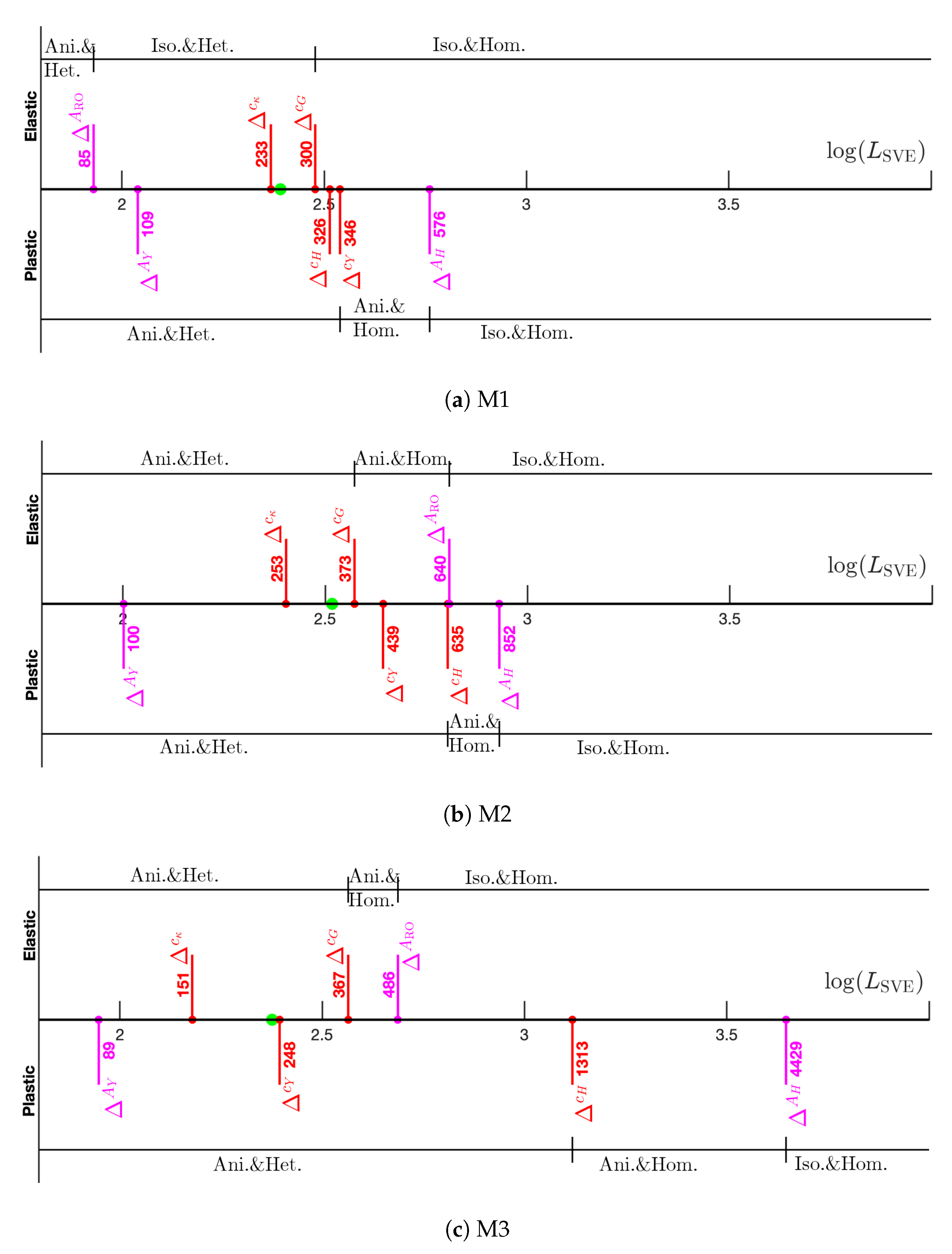
Figure 12 summarizes the form of the apparent properties versus the SVE size for the three materials. The homogeneity limits correspond to the size at which the coefficient of variation in the homogenized properties falls below the tolerance ϵ = 0.01 . The values for volume fraction, taken from Table 2, are shown by green circles. The homogeneity limits for elastic and plastic properties are taken from Table 3 and Table 4, respectively, and are shown by red lines. The elastic homogeneity limit is taken as the maximum of Δ c κ and Δ c G and the corresponding value for plastic properties is taken as the maximum of Δ c Y and Δ c H . The isotropy limits for elastic and plastic properties, shown by magenta lines, are determined from the process discussed in Section 3.4. For elastic properties, the spatial and sample-to-sample variations of the elasticity tensor can be neglected beyond the homogeneity limit. That is, a constant representation of C suffices. In addition, if the observation size ( L SVE ) is larger than the isotropy limit, this matrix is uniquely determined by the RVE limit κ and G. A similar logic applies to the homogenized plastic properties.
The results can be summarized as follows. The elastic field can be considered homogeneous and isotropic for M1 if L SVE ≳ 300. For the plastic fields, the yield strength Y tends to its homogeneity and isotropy limits faster than the hardening modulus H. The plastic properties can not be characterized as isotropic and homogeneous until L SVE ≳ 576 for M1. While similar trends are observed for M2 and M3, we note the following. First, the L SVE of plastic properties is significantly larger for M3 than for M1 and M2. Second, despite achieving isotropy in elastic properties, the material can remain anisotropic in its plastic response, especially in materials with higher volume fractions of the harder phase.

4. Conclusions

We used SVE homogenization to study the size dependency of elastic and plastic properties in a two-phase metallic polycrystalline material by varying the volume fractions of ferrite and martensite phases with random grain orientations. The SVEs were generated by partitioning a large domain using the moving window method and were simulated by CPFEM. Referring to Table 6 which, summarizes the effective mechanical properties and RVE sizes, and considering other results we draw the following conclusions,
  • For both geometry ( v f ) and elastic properties, the largest RVE is required for M2. This ordering is justified as M2 has the highest point-wise variation in volume fraction. In contrast, for plastic properties, the RVE size monotonically increases as V f increases from 10% to 90% for M1 to M3.
  • The smallest RVE size corresponds to the geometry property v f , followed by elastic properties ( L RVE e about equal to twice larger than the geometry RVE size), and plastic properties. The combined elastoplastic RVE size has the highest variation across the three materials with L RVE e p 1.5 to 9 L RVE e . The corresponding RVE size ranges (geometry, elastic, and elastoplastic) are approximately 250 to 330, 300 to 640, and 600 to 4400 μ m (50 to 66, 60 to 128, and 120 to 880 for L RVE / d ¯ , grains along the RVE edge) for the three materials considered. Given that d ¯ is the key inherent length scale of the material, L RVE / d ¯ can be considered as the scale factor of the RVE size.
  • The homogenized hardening modulus H shows a higher variability and anisotropy than the yield strength Y. This parameter is the main driver of large plastic RVE sizes, especially for M3 where the inclusion of H increases this size by approximately threefold. In fact, except for the response of H for M3, all the RVEs are smaller than 1 mm ( L RVE < 200 d ¯ ).
  • The isotropic and homogeneous elastic and plastic effective properties shown in Table 6 can be used for a bulk plasticity model. We believe that the macroscopic domain should be in the cm range or larger (at least for M3) to justify the use of these bulk-effective properties.
We conclude by mentioning potential extensions of this work. First, the effect of other microstructural features such as grain size, shape, and orientation distributions can be considered. Second, CPFEM and SVE-based analysis using the moving window method lend themselves to fatigue crack nucleation and propagation and as well as other problems that exhibit high statistical variability and size dependency. Third, CP models with an internal length scale, e.g., [34,38,40], can be used to provide a more accurate size-dependency of material properties, especially for smaller SVEs. Finally, the CPFEM of SVEs can provide random field material properties and constitutive equations for a stochastic continuum plasticity model.

Author Contributions

Conceptualization, A.D.A., R.A. and S.T.; methodology, A.D.A., R.A. and S.T.; software, A.D.A. and R.F.; formal analysis, A.D.A.; resources, R.A. and S.T.; writing—original draft preparation, A.D.A.; writing—review and editing, R.F., R.A. and S.T.; visualization, A.D.A.; supervision, R.A. and S.T.; funding acquisition, R.A and S.T. All authors have read and agreed to the published version of the manuscript.

Funding

This research was funded by Air Force Office of Scientific Research (AFOSR) under grant number FA9550-22-1-0359.

Institutional Review Board Statement

Not applicable.

Informed Consent Statement

Not applicable.

Data Availability Statement

The data presented in this study are available on request from the corresponding author. The data are not publicly available as the material and data are part of ongoing research.

Conflicts of Interest

The authors declare no conflict of interest. The funders had no role in the design of the study; in the collection, analyses, or interpretation of data; in the writing of the manuscript; or in the decision to publish the results.

Abbreviations

VEVolume Element
RVERepresentative Volume Element
SVEStatistical Volume Element
CPCrystal Plasticity
FEMFinite Element Method
CPFEMCrystal Plasticity Finite Element Method
ODFOrientation Distribution Function
MBCMixed Boundary Condition
KUBCKinematic Uniform Boundary Condition
SUBCStatic Uniform Boundary Condition

References

  1. Roters, F.; Eisenlohr, P.; Hantcherli, L.; Tjahjanto, D.D.; Bieler, T.R.; Raabe, D. Overview of constitutive laws, kinematics, homogenization and multiscale methods in crystal plasticity finite-element modeling: Theory, experiments, applications. Acta Mater. 2010, 58, 1152–1211. [Google Scholar] [CrossRef]
  2. Ostoja-Starzewski, M. Microstructural randomness versus representative volume element in thermomechanics. J. Appl. Mech.-Trans. ASME 2002, 69, 25–35. [Google Scholar] [CrossRef]
  3. Kaminski, M.; Kleiber, M. Numerical homogenization of N-component composites including stochastic interface defects. Int. J. Numer. Methods Eng. 2000, 47, 1001–1027. [Google Scholar] [CrossRef]
  4. Sakata, S.; Ashida, F.; Zako, M. Kriging-based approximate stochastic homogenization analysis for composite materials. Comput. Methods Appl. Mech. Eng. 2008, 197, 1953–1964. [Google Scholar] [CrossRef]
  5. Sakata, S.; Ashida, F.; Enya, K. A microscopic failure probability analysis of a unidirectional fiber reinforced composite material via a multiscale stochastic stress analysis for a microscopic random variation of an elastic property. Comput. Mater. Sci. 2012, 62, 35–46. [Google Scholar] [CrossRef]
  6. Sakata, S.; Ashida, F.; Ohsumimoto, K. Stochastic homogenization analysis of a porous material with the perturbation method considering a microscopic geometrical random variation. Int. J. Mech. Sci. 2013, 77, 145–154. [Google Scholar] [CrossRef]
  7. Huyse, L.; Maes, M. Random field modeling of elastic properties using homogenization. J. Eng. Mech. 2001, 127, 27–36. [Google Scholar] [CrossRef]
  8. Segurado, J.; LLorca, J. Computational micromechanics of composites: The effect of particle spatial distribution. Mech. Mater. 2006, 38, 873–883. [Google Scholar] [CrossRef]
  9. Tregger, N.; Corr, D.; Graham-Brady, L.; Shah, S. Modeling the effect of mesoscale randomness on concrete fracture. Probabilistic Eng. Mech. 2006, 21, 217–225. [Google Scholar] [CrossRef]
  10. Baxter, S.C.; Graham, L.L. Characterization of random composites using moving-window technique. J. Eng. Mech. 2000, 126, 389–397. [Google Scholar] [CrossRef]
  11. Hill, R. Elastic properties of reinforced solids: Some theoretical principles. J. Mech. Phys. Solids 1963, 11, 357–372. [Google Scholar] [CrossRef]
  12. Ostoja-Starzewski, M.; Kale, S.; Karimi, P.; Malyarenko, A.; Raghavan, B.; Ranganathan, S.I.; Zhang, J. Scaling to RVE in random media. Adv. Appl. Mech. 2016, 49, 111–211. [Google Scholar]
  13. Abedi, R.; Garrard, J.; Acton, K. Elastic and strength properties of statistical volume elements: Determination of isotropic and homogeneous size limits. Comput. Struct. 2023, 277, 106959. [Google Scholar] [CrossRef]
  14. Graham-Brady, L.; Siragy, E.; Baxter, S. Analysis of heterogeneous composites based on moving-window techniques. J. Eng. Mech. 2003, 129, 1054–1064. [Google Scholar] [CrossRef]
  15. Abedi, R.; Garrard, J.; Yang, M.; Acton, K.; Soghrati, S. Effect of boundary condition and statistical volume element size on inhomogeneity and anisotropy of apparent properties. Mech. Mater. 2022, 173, 104408. [Google Scholar] [CrossRef]
  16. Kanit, T.; Forest, S.; Galliet, I.; Mounoury, V.; Jeulin, D. Determination of the size of the representative volume element for random composites: Statistical and numerical approach. Int. J. Solids Struct. 2003, 40, 3647–3679. [Google Scholar] [CrossRef]
  17. Shenoy, M.; Zhang, J.; McDowell, D.L. Estimating fatigue sensitivity to polycrystalline Ni-base superalloy microstructures using a computational approach. Fatigue Fract. Eng. Mater. Struct. 2007, 30, 889–904. [Google Scholar] [CrossRef]
  18. Teferra, K.; Graham-Brady, L. A random field-based method to estimate convergence of apparent properties in computational homogenization. Comput. Methods Appl. Mech. Eng. 2018, 330, 253–270. [Google Scholar] [CrossRef]
  19. Saroukhani, S.; Vafadari, R.; Andersson, R.; Larsson, F.; Runesson, K. On statistical strain and stress energy bounds from homogenization and virtual testing. Eur. J. Mech.-A/Solids 2015, 51, 77–95. [Google Scholar] [CrossRef]
  20. Ranganathan, S.I.; Ostoja-Starzewski, M. Scale-Dependent Homogenization of Inelastic Random Polycrystals. J. Appl. Mech. 2008, 75, 051008. [Google Scholar] [CrossRef]
  21. Pinz, M.; Weber, G.; Lenthe, W.; Uchic, M.; Pollock, T.; Ghosh, S. Microstructure and property based statistically equivalent RVEs for intragranular γ- γ’microstructures of Ni-based superalloys. Acta Mater. 2018, 157, 245–258. [Google Scholar] [CrossRef]
  22. Tu, X.; Shahba, A.; Shen, J.; Ghosh, S. Microstructure and property based statistically equivalent RVEs for polycrystalline-polyphase aluminum alloys. Int. J. Plast. 2019, 115, 268–292. [Google Scholar] [CrossRef]
  23. Salahouelhadj, A.; Haddadi, H. Estimation of the size of the RVE for isotropic copper polycrystals by using elastic–plastic finite element homogenisation. Comput. Mater. Sci. 2010, 48, 447–455. [Google Scholar] [CrossRef]
  24. Yang, S.; Dirrenberger, J.; Monteiro, E.; Ranc, N. Representative volume element size determination for viscoplastic properties in polycrystalline materials. Int. J. Solids Struct. 2019, 158, 210–219. [Google Scholar] [CrossRef]
  25. Tucker, J.C.; Cerrone, A.R.; Ingraffea, A.R.; Rollett, A.D. Crystal plasticity finite element analysis for René88DT statistical volume element generation. Model. Simul. Mater. Sci. Eng. 2015, 23, 035003. [Google Scholar] [CrossRef]
  26. Bouchedjra, M.; Kanit, T.; Boulemia, C.; Amrouche, A.; Belouchrani, M.E.A. Determination of the RVE size for polycrystal metals to predict monotonic and cyclic elastoplastic behavior: Statistical and numerical approach with new criteria. Eur. J. Mech.-A/Solids 2018, 72, 1–15. [Google Scholar] [CrossRef]
  27. Lim, H.; Battaile, C.C.; Bishop, J.E.; Foulk III, J.W. Investigating mesh sensitivity and polycrystalline RVEs in crystal plasticity finite element simulations. Int. J. Plast. 2019, 121, 101–115. [Google Scholar] [CrossRef]
  28. Askes, H.; Suiker, A.; Sluys, L. A classification of higher-order strain-gradient models–linear analysis. Arch. Appl. Mech. 2002, 72, 171–188. [Google Scholar] [CrossRef]
  29. Pijaudier-Cabot, G.; Bažant, Z.P. Nonlocal damage theory. J. Eng. Mech. 1987, 113, 1512–1533. [Google Scholar] [CrossRef]
  30. Peerlings, R.H.; de Borst, R.; Brekelmans, W.M.; de Vree, J. Gradient enhanced damage for quasi-brittle materials. Int. J. Numer. Methods Eng. 1996, 39, 3391–3403. [Google Scholar] [CrossRef]
  31. Bourdin, B.; Francfort, G.A.; Marigo, J.J. The variational approach to fracture. J. Elast. 2008, 91, 5–148. [Google Scholar] [CrossRef]
  32. Miehe, C.; Welschinger, F.; Hofacker, M. Thermodynamically consistent phase-field models of fracture: Variational principles and multi-field FE implementations. Int. J. Numer. Methods Eng. 2010, 83, 1273–1311. [Google Scholar] [CrossRef]
  33. Bažant, Z.P. Size effect. Int. J. Solids Struct. 2000, 37, 69–80. [Google Scholar] [CrossRef]
  34. Greer, J.R.; De Hosson, J.T.M. Plasticity in small-sized metallic systems: Intrinsic versus extrinsic size effect. Prog. Mater. Sci. 2011, 56, 654–724. [Google Scholar] [CrossRef]
  35. Moghaddam, M.G.; Achuthan, A.; Bednarcyk, B.A.; Arnold, S.M.; Pineda, E.J. Grain size-dependent crystal plasticity constitutive model for polycrystal materials. Mater. Sci. Eng. A 2017, 703, 521–532. [Google Scholar] [CrossRef]
  36. Lin, P.; Liu, Z.; Zhuang, Z. Numerical study of the size-dependent deformation morphology in micropillar compressions by a dislocation-based crystal plasticity model. Int. J. Plast. 2016, 87, 32–47. [Google Scholar] [CrossRef]
  37. Agius, D.; Kareer, A.; Al Mamun, A.; Truman, C.; Collins, D.M.; Mostafavi, M.; Knowles, D. A crystal plasticity model that accounts for grain size effects and slip system interactions on the deformation of austenitic stainless steels. Int. J. Plast. 2022, 152, 103249. [Google Scholar] [CrossRef]
  38. Ask, A.; Forest, S.; Appolaire, B.; Ammar, K.; Salman, O.U. A cosserat crystal plasticity and phase field theory for grain boundary migration. J. Mech. Phys. Solids 2018, 115, 167–194. [Google Scholar] [CrossRef]
  39. Trovalusci, P.; Ostoja-Starzewski, M.; De Bellis, M.L.; Murrali, A. Scale-dependent homogenization of random composites as micropolar continua. Eur. J. Mech.-A/Solids 2015, 49, 396–407. [Google Scholar] [CrossRef]
  40. Nellemann, C.; Niordson, C.; Nielsen, K. Hardening and strengthening behavior in rate-independent strain gradient crystal plasticity. Eur. J. Mech.-A/Solids 2018, 67, 157–168. [Google Scholar] [CrossRef]
  41. Quey, R.; Dawson, P.R.; Barbe, F. Large-scale 3D random polycrystals for the finite element method: Generation, meshing and remeshing. Comput. Methods Appl. Mech. Eng. 2011, 200, 1729–1745. [Google Scholar] [CrossRef]
  42. Groeber, M.A.; Jackson, M.A. DREAM. 3D: A digital representation environment for the analysis of microstructure in 3D. Integr. Mater. Manuf. Innov. 2014, 3, 56–72. [Google Scholar] [CrossRef]
  43. Ghosh, S.; Dimiduk, D.; Furrer, D. Statistically equivalent representative volume elements (SERVE) for material behaviour analysis and multiscale modelling. Int. Mater. Rev. 2023, 68, 1158–1191. [Google Scholar] [CrossRef]
  44. Roters, F.; Eisenlohr, P.; Bieler, T.R.; Raabe, D. Crystal Plasticity Finite Element Methods: In Materials Science and Engineering; John Wiley & Sons: Hoboken, NJ, USA, 2011. [Google Scholar]
  45. Graham, L.; Baxter, S. Simulation of local material properties based on moving-window GMC. Probabilistic Eng. Mech. 2001, 16, 295–305. [Google Scholar] [CrossRef]
  46. Huet, C. Application of variational concepts to size effects in elastic heterogeneous bodies. J. Mech. Phys. Solids 1990, 38, 813–841. [Google Scholar] [CrossRef]
  47. Hardie, C.; Long, D.J.; Demir, E.; Tarleton, E.; Dunne, F.P. A robust and efficient hybrid solver for crystal plasticity. Int. J. Plast. 2023, 170, 103773. [Google Scholar] [CrossRef]
  48. Eghtesad, A.; Knezevic, M. High-performance full-field crystal plasticity with dislocation-based hardening and slip system back-stress laws: Application to modeling deformation of dual-phase steels. J. Mech. Phys. Solids 2020, 134, 103750. [Google Scholar] [CrossRef]
  49. Tasan, C.C.; Diehl, M.; Yan, D.; Zambaldi, C.; Shanthraj, P.; Roters, F.; Raabe, D. Integrated experimental–simulation analysis of stress and strain partitioning in multiphase alloys. Acta Mater. 2014, 81, 386–400. [Google Scholar] [CrossRef]
  50. Cantara, A.M.; Zecevic, M.; Eghtesad, A.; Poulin, C.M.; Knezevic, M. Predicting elastic anisotropy of dual-phase steels based on crystal mechanics and microstructure. Int. J. Mech. Sci. 2019, 151, 639–649. [Google Scholar] [CrossRef]
  51. Liu, W.; Lian, J.; Aravas, N.; Münstermann, S. A strategy for synthetic microstructure generation and crystal plasticity parameter calibration of fine-grain-structured dual-phase steel. Int. J. Plast. 2020, 126, 102614. [Google Scholar] [CrossRef]
  52. Khisaeva, Z.; Ostoja-Starzewski, M. On the size of RVE in finite elasticity of random composites. J. Elast. 2006, 85, 153–173. [Google Scholar] [CrossRef]
  53. Hazanov, S.; Huet, C. Order relationships for boundary conditions effect in heterogeneous bodies smaller than the representative volume. J. Mech. Phys. Solids 1994, 42, 1995–2011. [Google Scholar] [CrossRef]
  54. Acton, K.; Garrard, J.; Abedi, R. Geometric partitioning schemes to reduce modeling bias in statistical volume elements smaller than the scale of isotropic and homogeneous size limits. Comput. Methods Appl. Mech. Eng. 2022, 393, 114772. [Google Scholar] [CrossRef]
  55. Zener, C.M.; Siegel, S. Elasticity and Anelasticity of Metals. J. Phys. Chem. 1949, 53, 1468. [Google Scholar] [CrossRef]
  56. Chung, D.; Buessem, W. The elastic anisotropy of crystals. J. Appl. Phys. 1967, 38, 2010–2012. [Google Scholar] [CrossRef]
  57. Ranganathan, S.I.; Murshed, M.R.; Costa, L. Heterogeneous Anisotropy Index and scaling in two-phase random polycrystals. Acta Mech. 2018, 229, 2631–2646. [Google Scholar] [CrossRef]
  58. Ranganathan, S.I.; Ostoja-Starzewski, M. Universal elastic anisotropy index. Phys. Rev. Lett. 2008, 101, 055504. [Google Scholar] [CrossRef] [PubMed]
  59. Nye, J.F. Physical Properties of Crystals: Their Representation by Tensors and Matrices; Oxford University Press: Oxford, UK, 1985. [Google Scholar]
  60. Rychlewski, J.; Zhang, J. Anisotropy degree of elastic materials. Arch. Mech 1989, 47, 697–715. [Google Scholar]
  61. Acton, K.; Sherod, C.; Bahmani, B.; Abedi, R. Effect of Volume Element Geometry on Convergence to a Representative Volume. ASCE-ASME J. Risk Uncertain. Eng. Syst. Part B Mech. Eng. 2019, 5, 030907. [Google Scholar] [CrossRef]
  62. Yang, M.; Garrard, J.; Abedi, R.; Soghrati, S. Effect of microstructural variations on the failure response of a nano-enhanced polymer: A homogenization-based statistical analysis. Comput. Mech. 2021, 67, 315–340. [Google Scholar] [CrossRef]
  63. Matheron, G. The Theory of Regionalized Variables and Its Applications, Vol. 5; École National Supérieure des Mines: Paris, France, 1971; Volume 211. [Google Scholar]
  64. Lantuejoul, C. Geostatistical Simulation: Models and Algorithms; Springer Science & Business Media: Berlin, Germany, 2002. [Google Scholar] [CrossRef]
  65. Bahmani, B.; Yang, M.; Nagarajan, A.; Clarke, P.L.; Soghrati, S.; Abedi, R. Automated homogenization-based fracture analysis: Effects of SVE size and boundary condition. Comput. Methods Appl. Mech. Eng. 2019, 345, 701–727. [Google Scholar] [CrossRef]
  66. Acton, K.A.; Baxter, S.C.; Bahmani, B.; Clarke, P.L.; Abedi, R. Voronoi tessellation based statistical volume element characterization for use in fracture modeling. Comput. Methods Appl. Mech. Eng. 2018, 336, 135–155. [Google Scholar] [CrossRef]
  67. Karimi, P.; Malyarenko, A.; Ostoja-Starzewski, M.; Zhang, X. RVE Problem: Mathematical aspects and related stochastic mechanics. Int. J. Eng. Sci. 2020, 146, 103169. [Google Scholar] [CrossRef]
  68. Malyarenko, A.; Ostoja-Starzewski, M. Tensor Random Fields in Continuum Mechanics. In Encyclopedia of Continuum Mechanics; Springer: Berlin/Heidelberg, Germany, 2020; pp. 2433–2441. [Google Scholar]
Figure 1. Three generated polycrystalline domains with two phases (a) Material 1 (M1), (b) Material 2 (M2), and (c) Material 3 (M3) with volume fraction of martensite 10%, 45%, and 90%, respectively. Red and blue represent martensite and ferrite, respectively. (d) Distribution of grains across different phases of the generated material.
Applsci 14 08207 g001
Figure 2. The moving window method applied to create SVEs of different sizes. (a) L SVE = 50 μ m, (b) L SVE = 100 μ m, (c) L SVE = 200 μ m, and (d) L SVE = 400 μ m.
Applsci 14 08207 g002
Figure 3. PDFs of the (a) bulk modulus, κ , and (b) average yield stress, Y, for M2, L SVE = 50 μ m, and different mesh sizes ( h = 4 μ m, h = 2 μ m, and h = 1 μ m).
Applsci 14 08207 g003
Figure 4. (a) Minimum, mean, and maximum of v f versus L SVE for the three materials. (b) Convergence of SVE size to Δ D f for volume fraction, v f . Individual markers represent numerical results, and dashed lines represent the linear regression fit. The green line at the ordinate of −2 corresponds to the RVE limit for ϵ = 0.01 .
Applsci 14 08207 g004
Figure 5. Minimum, mean, and maximum of (a) bulk modulus, κ , and (b) shear modulus, G, versus L SVE for the three materials.
Applsci 14 08207 g005
Figure 6. Convergence of SVE size to Δ c f for (a) bulk modulus, κ , and (b) shear modulus, G. Individual markers represent numerical results, and dashed lines represent the linear regression fit. The green line at the ordinate of −2 corresponds to the RVE limit for ϵ = 0.01 .
Applsci 14 08207 g006
Figure 7. Stress-strain curves for all the SVE sizes loaded in the x direction. (a) L SVE = 50 μ m (b) L SVE = 100 μ m (c) L SVE = 200 μ m and (d) L SVE = 400 μ m. The dots denote the yield points.
Applsci 14 08207 g007aApplsci 14 08207 g007b
Figure 8. Minimum, mean, and maximum of (a) yield strength, Y and (b) plastic hardening modulus, H, versus L SVE for the three materials.
Applsci 14 08207 g008
Figure 9. Convergence of SVE size to Δ c f for the (a) yield strength, Y and (b) plastic hardening modulus, H versus L SVE for the three materials. Individual markers represent numerical results, and dashed lines represent the linear regression fit. The green line at the ordinate of −2 corresponds to the RVE limit for ϵ = 0.01 .
Applsci 14 08207 g009
Figure 10. Minimum, mean, and maximum of anisotropy indices (a) A RO for elasticity, (b) A Y for yield strength, and (c) A H for plastic hardening versus the SVE size.
Applsci 14 08207 g010
Figure 11. Convergence of SVE size to Δ D f for anisotropy indices (a) A RO for elasticity, (b) A Y for yield strength, and (c) A H for plastic hardening. Individual markers represent numerical results, and dashed lines represent linear regression fit. The green line at the ordinate of −2 corresponds to the RVE limit for ϵ = 0.01 .
Applsci 14 08207 g011
Figure 12. Summary of the homogeneous and isotropic limits of geometric (volume fraction), elastic and plastic properties. Green dots denote the RVE limit for volume fraction. Red and magenta represent the homogenous and anisotropic RVE limits, respectively. The abbreviations Iso., Ani., Hom., and Het. denote isotropic, anisotropic, homogenous, and heterogenous, respectively.
Applsci 14 08207 g012
Table 1. The model parameters of ferrite and martensite.
Phase C 11 (GPa) C 12 (GPa) C 33 (GPa) γ ˙ 0 n h 0 S s (MPa)m
Martensite417.40242.40211.100.0012040,0007002.5
Ferrite218.37113.31105.340.0012045003701.3
Table 2. Convergence and power law fit data for volume fraction v f and ϵ = 0.01 .
Material α v f b v f Δ D v f
M11.30213.018246.57
M21.40935.234328.67
M31.31113.011237.76
Table 3. Convergence and power law fit data for elastic properties and ϵ = 0.01 .
Materialf α f b f Δ c f
M1 κ 1.26810.057233.35
G1.0423.822300.44
M2 κ 1.41425.072253.05
G1.1177.459373.45
M3 κ 1.3127.210150.87
G0.9122.175366.65
Table 4. Convergence and power law fit data for plastic properties and ϵ = 0.01 .
Materialf α f b f Δ c f
M1Y1.39033.859345.93
H1.1146.320326.37
M2Y1.25220.381439.38
H1.14616.244634.75
M3Y1.2097.864248.11
H1.07222.0941312.96
Table 5. Convergence and power law fit data for the anisotropy measures and ϵ = 0.01 . The isotropy limit Δ f is shown in the last columns.
Materialf α f b f Δ D f α f ¯ b f ¯ Δ f ¯ Δ f
A RO 1.0340.98682.660.3650.05185.0785.07
M1 A Y 1.3305.095108.631.0501.384109.39109.39
A H 0.8922.427470.880.9323.732576.00576.00
A RO 0.9671.178138.550.3150.076640.49640.49
M2 A Y 1.1211.50987.860.9200.693100.34100.34
A H 1.0017.834734.261.03911.079851.78851.78
A RO 1.0601.606120.490.3170.071486.44486.44
M3 A Y 0.9240.48366.420.8760.50788.6488.64
A H 0.99525.4612653.100.87815.8434429.034429.03
Table 6. Summary of elastic L RVE e and elastoplastic L RVE e p RVE sizes and corresponding effective elastic and plastic properties.
Material L RVE e ( μ m) L RVE e / d ¯ κ (GPa)G (GPa) L RVE e p ( μ m) L RVE e p / d ¯ Y (MPa)H (MPa)
M1300.4460.09194.1186.09576.00115.20747.911848.85
M2640.49128.09255.18108.45851.78170.361334.711277.37
M3486.4497.29335.12140.714429.03885.811966.94526.09
Disclaimer/Publisher’s Note: The statements, opinions and data contained in all publications are solely those of the individual author(s) and contributor(s) and not of MDPI and/or the editor(s). MDPI and/or the editor(s) disclaim responsibility for any injury to people or property resulting from any ideas, methods, instructions or products referred to in the content.